Embed Size (px)
Citation preview
Pressure Control
Shaffer Ram BOPs
Pressure ControlShaffer Ram BOPs
Shaffer Ram BOPs Outstanding FeaturesShaffer ram BOPs offer field-proven reliability in sealing around drill pipe and across open hole and for shearing drill pipe.
■ Minimum maintenance space is required. Shaffer rams have a low overall height compared with other ram preventers.
■ Single, double and triple models are available. The double and triple models save space and weight by combining two or three ram compartments into one unitized body.
■ Full environmental H2S trim, conforming to API and NACE requirements, is available.
■ Self-draining body has a ram compartment with skids to support the rams and a sloped bottom which allows mud and sand to drain back into the well bore. This keeps the ram cavity free of caked mud and debris.
■ Ram rubbers have a long life in routine drilling operations and in stripping.
■ Rams can be changed easily without breaking or remaking hydraulic connections, even with pipe in the hole.
■ Single piston hydraulic operators have a minimum number of working parts. This assures high reliability and low maintenance.
■ Flanged, hubbed or studded connections are available for end connections and side outlets of most models.
65
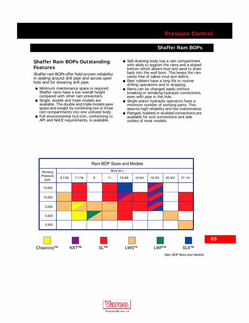
Ram BOP Sizes and Models
66
Pressure Control
Shaffer Ram BOPs
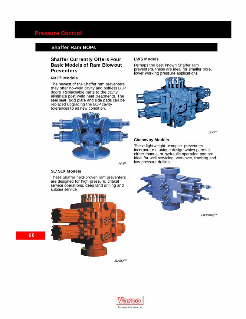
Shaffer Currently Offers Four Basic Models of Ram Blowout PreventersNXT® ModelsThe newest of the Shaffer ram preventers, they offer no-weld cavity and boltless BOP doors. Replaceable parts to the cavity eliminate post weld heat treatments. The seal seat, skid plate and side pads can be replaced upgrading the BOP cavity tolerances to as new condition.
NXT®
SL/SLX ModelsThese Shaffer field-proven ram preventers are designed for high pressure, critical service operations, deep land drilling and subsea service.
SL/SLX™
LWS ModelsPerhaps the best known Shaffer ram preventers, these are ideal for smaller bore, lower working pressure applications.
LWS™
Chasovoy ModelsThese lightweight, compact preventers incorporate a unique design which permits either manual or hydraulic operation and are ideal for well servicing, workover, fracking and low pressure drilling.
Chasovoy™
Pressure Control
Shaffer NXT® Ram BOPs
Shaffer NXT® Ram BOPs
NXT® Double BOP
67
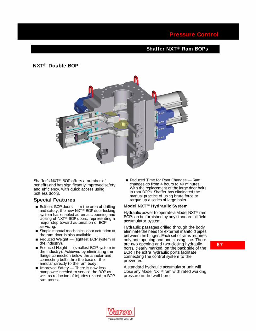
Shaffer’s NXT® BOP offers a number of benefits and has significantly improved safety and efficiency, with quick access using boltless doors.
Special Features■ Boltless BOP doors — In the area of drilling
and safety, the new NXT® BOP door locking system has enabled automatic opening and closing of NXT® BOP doors, representing a major step toward automation of BOP servicing.
■ Simple manual mechanical door actuation at the ram door is also available.
■ Reduced Weight — (lightest BOP system in the industry).
■ Reduced Height — (smallest BOP system in the industry). Achieved by eliminating the flange connection below the annular and connecting bolts thru the base of the annular directly to the ram body.
■ Improved Safety — There is now less manpower needed to service the BOP as well as reduction of injuries related to BOP ram access.
■ Reduced Time for Ram Changes — Ram changes go from 4 hours to 40 minutes.With the replacement of the large door bolts in ram BOPs, Shaffer has eliminated the manual practice of using brute force to torque up a series of large bolts.
Model NXT™ Hydraulic SystemHydraulic power to operate a Model NXT® ram BOP can be furnished by any standard oil field accumulator system.Hydraulic passages drilled through the body eliminate the need for external manifold pipes between the hinges. Each set of rams requires only one opening and one closing line. There are two opening and two closing hydraulic ports, clearly marked, on the back side of the BOP. The extra hydraulic ports facilitate connecting the control system to the preventer.A standard hydraulic accumulator unit will close any Model NXT® ram with rated working pressure in the well bore.
68
Pressure Control
Shaffer NXT® Ram BOPs
Model NXT®
Ultralock™ Ram Locking SystemThe UltraLock II locking system incorporates a mechanical locking mechanism within the piston assembly. This locking system is not dependent on closing pressure to maintain a positive lock. It uses flat tapered locking segments carried by the operating piston which engages another stationery tapered shaft located within the operating cylinder. Using SL-D rams, the UltraLock II has hang-off capabilities up to 600,000 pounds at full working pressure. The system needs no adjustments, no matter the size of the pipe rams. Different size or type ram assemblies can be freely interchanged. Only one hydraulic function is required to operate the cylinder’s open/close function and the locking system. The system automatically locks in the closed position each time the piston assembly is closed. Once the operating piston is closed on the pipe, the locks are engaged until opening pressure is applied. Only hydraulic pressure can unlock and reopen the preventer. Model NXT® Poslock SystemNXT® preventers equipped with Poslock pistons are locked automatically in the closed position each time they are closed. The preventers will remain locked in the closed position even if closing pressure is removed. Open hydraulic pressure is required to reopen the pistons.The hydraulics required to operate the Poslock are provided through opening and closing operating ports. Operation of the Poslock requires no additional hydraulic functions, such as are required in some competitive ram locking systems.
Model NXT® Manual-Lock SystemsManual-lock pistons move inward and close the rams when closing hydraulic pressure is applied. If desired, the rams can be manually locked in the closed position by turning each locking shaft to the right until it shoulders against the cylinder head. Should hydraulic pressure fail, the rams can be manually closed and locked. They cannot be manually reopened.Door Operating PrincipleThe NXT® “Boltless Door” assembly is mechanized using hydraulics to lock, unlock, open and close the door. The lock and unlock process is done with hydraulic cylinders mounted on the doors used to engage and disengage a locking bar system. These load bearing lock bars, housed in the door grooves, lock the door and body together.Control Manifold OptionHydraulic door functions are operated through a control manifold assembly. The assembly is mounted to a plate for convenient customer installation.

Pressure Control
Shaffer No-Weld Cavity Ram BOPs
Shaffer No-Weld Cavity Ram BOPs
Shaffer introduced a no-weld cavity feature in the SLX model ram blowout preventer. The no-weld cavity is a feature which allows upgrade of the BOP to new condition. Post-weld heat treatments are eliminated.
This no-weld cavity has a replaceable seal seat, a replaceable skid plate and replaceable side pads.
The no-weld cavity is standard on the NXT® ram BOP, an available option on the SLX ram BOP, and available as a retrofit on some SL ram BOP sizes.
69
Shaffer SL Triple BOP with two doors open
Replaceable Seal Seat
Replaceable Side Pads
Replaceable Skid Plate

70
Pressure Control
Shaffer SL/SLX Ram BOPs
Shaffer SL/SLX Ram BOPs
Shaffer Model SL/SLX ram blowout preventers are the product of more than 80 years of experience in building ram BOPs to meet the changing demands of the petroleum industry. SL models incorporate the improvements made in the LWS preventer line over the past 44 years — improvements resulting from continuing research to ensure that Shaffer preventers meet or surpass the latest industry requirements.
Special Features■ Flat doors simplify ram changes. To
change the rams, apply opening hydraulic pressure to move the rams to the full open position. Vent hydraulic pressure. Remove the door cap screws and swing the door open. Remove the ram from the ram shaft and replace it. It is not necessary to apply closing hydraulic pressure to move the rams inward to clear the door.
■ SL Model door seals (most sizes) have a hard backing molded into the rubber. This backing prevents extrusion and pinching at all pressures to assure long seal life.
■ SLX Model features a Pressure-Energized Door Seal. This new design cartridge seal assembly employs a radial seal to pressure assist a face seal and prevent extrusion. This feature allows reduced door bolt torque.
■ Internal H2S trim is standard. All major components conform to API requirements.
■ Maximum ram hardness is Rc22 to insure H2S compatibility of pipe and blind rams. Shear rams have some harder components.
■ Poslock operators lock the rams automatically each time they are closed. This eliminates the cost of a second hydraulic function to lock. It also simplifies emergency operation because the rams are both closed and locked just by activating the close function.
■ Manual-lock and Poslock pistons can be interchanged on the same door by replacing the ram shaft, piston assembly and cylinder head.
■ Wear rings eliminate metal-to-metal contact between the piston and cylinder to increase seal life and virtually eliminate cylinder bore wear.
■ Lip type piston seals are long-wearing polyurethane with molybdenum disulfide molded in for lifetime lubrication.
■ Lip type ram shaft seals hold the well bore pressure and the opening hydraulic pressure.
■ Secondary ram shaft seals permit injection of plastic packing if the primary lip type seal ever fails. Fluid dripping from the weep hole in the door indicates that the primary seal is leaking and that the secondary seal should be energized.
SL Triple BOP

Pressure Control
Shaffer SL/SLX Ram BOPs
Special Features, Continued■ Rams are available which will support a
600,000 pound drill string when a tool joint is lowered onto the closed rams. These rams conform to H2S requirements.
■ Shear rams cut drill pipe and seal in one operation. Most common weights and grades of drill pipe are sheared with less than 1,500 psi hydraulic pressure using 14” cylinders. Some grades and weights require higher hydraulic pressures.
Model SL/SLX Hydraulic SystemHydraulic power to operate a Model SL/SLX ram BOP can be furnished by any standard oil field accumulator system.Hydraulic passages drilled through the body eliminate the need for external manifold pipes between the hinges. Each set of rams requires only one opening and one closing line. There are two opening and two closing hydraulic ports, clearly marked, on the back side of the BOP. The extra hydraulic ports facilitate connecting the control system to the preventer.A standard hydraulic accumulator unit will close any Model SL/SLX ram with rated working pressure in the well bore, except for the 7 1/16” , 11” and 13 5/8” -15,000 psi BOPs, which require 2,200 psi. However, these units will close against 10,000 psi well pressure with less than 1,500 psi hydraulic pressure.
71
SL Single BOP
Ram closing circuit Ram opening circuit
72
Pressure Control
Shaffer SL/SLX Ram BOP Operation
Shaffer SL/SLX Ram BOP Operation
Model SL/SLX Ultralock™ Ram Locking SystemThe UltraLock™ II locking system incorporates a mechanical locking mechanism within the piston assembly. This locking system is not dependent on closing pressure to maintain a positive lock. It uses flat tapered locking segments carried by the operating piston which engages another stationary tapered shaft located within the operating cylinder. Using SL-D rams, the UltraLock™ II has hang-off capabilities up to 600,000 pounds at full working pressure. The system needs no adjustments, no matter the size of the pipe ram. Different size or type ram assemblies can be freely interchanged. Only one hydraulic function is required to operate the cylinder’s open/close function and the locking system. The system automatically locks in the closed position each time the piston assembly is closed. Once the operating piston is closed on the pipe, the locks are engaged until opening pressure is applied. Only hydraulic pressure can unlock and reopen the preventer.Model SL/SLX Poslock SystemSL/SLX preventers equipped with Poslock pistons are locked automatically in the closed position each time they are closed. The preventers will remain locked in the closed position even if closing pressure is removed. Open hydraulic pressure is required to reopen the pistons.The hydraulics required to operate the Poslock are provided through opening and closing operating ports. Operation of the Poslock requires no additional hydraulic functions, such as are required in some competitive ram locking systems.
Model SL/SLX Manual-Lock SystemManual-lock pistons move inward and close the rams when closing hydraulic pressure is applied. If desired, the rams can be manually locked in the closed position by turning each locking shaft to the right until it shoulders against the cylinder head. Should hydraulic pressure fail, the rams can be manually closed and locked. They cannot be manually reopened.The manual locking shafts are visible from outside and provide a convenient ram position indicator. Threads on the manual locking shaft are enclosed in the hydraulic fluid and are not exposed to corrosion from mud and salt water or to freezing.Rams are opened by first turning both locking shafts to their unlocked position, then applying opening hydraulic pressure to the pistons, which move outward and pull the rams out of the well bore.

73
Pressure Control
Shaffer LWS Ram BOP Operation
Shaffer LWS Ram BOP Operation
Model LWS blowout preventers have been the most popular Shaffer Ram Preventers and have met the demanding pressure control requirements of the drilling industry for more than 20 years. Many of the features incorporated in the most advanced SL models are included in the LWS design.Special Features
■ Rams are available which will support a 600,000 pound drill string load when a tool joint is lowered onto the closed rams. These rams conform to H2S requirements.
■ Secondary ram shaft seals are furnished on all LWS preventers except 4 1/16” 5,000 and 10,000 psi; 7 1/16” 5,000 psi; and 11” 3,000 psi BOPs.
■ Rams are easily replaced. They slide horizontally onto the ram shaft except on the4 1/16” 10,000 psi BOP where the ram mounts onto the ram shaft from above.
■ Poslock operators are available on the 4 1/16” 5,000 and 10,000 psi, 20 3/4” 3,000 psi and 21 1/4” 2,000 psi LWS BOPs.
■ Manual-lock operators are furnished on all LWS BOPs not equipped with Poslock operators.
■ Maximum ram hardness is Rc22 to insure H2S compatibility of pipe and blind rams. Shear rams have some harder components.
Model LWS Hydraulic SystemThe hydraulic pressure required to close an LWS BOP is below 1,500 psi with rated well pressure in the bore. Any standard 1,500 psi oil field accumulator system can be used to actuate these BOPs.External hydraulic manifold pipes conduct the fluid between the hinges on all sizes except the 4 1/16” 5,000 and 10,000 psi, 20 3/4” 3,000 psi and 21 1/4” 2,000 psi LWS BOPs.
Model LWS Poslock SystemLWS Preventers equipped with Poslock pistons are locked automatically in the closed position each time they are closed. The preventers will remain locked in the closed position even if closing pressure is removed. Opening hydraulic pressure is required to reopen the pistons.The hydraulics required to operate the Poslock are provided through opening and closing operating ports. Operation of the Poslock requires no additional hydraulic functions, such as are required in some competitive ram locking systems.

74
Pressure Control
Shaffer LWS Ram BOP Operation
Model LWS Manual-Lock SystemManual-lock pistons move inward and close the rams when closing hydraulic pressure is applied. If desired, the rams can be manually locked in the closed position by turning each locking shaft to the right until it shoulders against the cylinder head. Should hydraulic pressure fail, the rams can be manually closed and locked. They cannot be manually reopened.The manual locking shafts are visible from outside and provide a convenient ram position indicator. Threads on the manual locking shaft are enclosed in the hydraulic fluid and are not exposed to corrosion from mud and salt water or to freezing.Rams are opened by first turning both locking shafts to their unlocked position, then applying opening hydraulic pressure to the pistons, which move outward and pull the rams out of the well bore.
LWS Manual Lock, closed and locked
LWS Manual Lock, open
75
Pressure Control
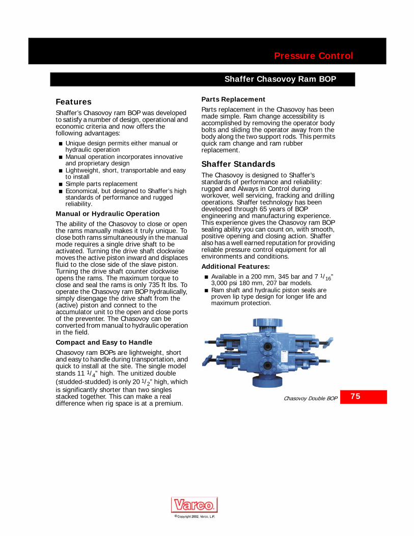
Shaffer Chasovoy Ram BOP
Shaffer Chasovoy Ram BOP
FeaturesShaffer’s Chasovoy ram BOP was developed to satisfy a number of design, operational and economic criteria and now offers the following advantages:
■ Unique design permits either manual or hydraulic operation
■ Manual operation incorporates innovative and proprietary design
■ Lightweight, short, transportable and easy to install
■ Simple parts replacement■ Economical, but designed to Shaffer’s high
standards of performance and rugged reliability.
Manual or Hydraulic OperationThe ability of the Chasovoy to close or open the rams manually makes it truly unique. To close both rams simultaneously in the manual mode requires a single drive shaft to be activated. Turning the drive shaft clockwise moves the active piston inward and displaces fluid to the close side of the slave piston. Turning the drive shaft counter clockwise opens the rams. The maximum torque to close and seal the rams is only 735 ft lbs. To operate the Chasovoy ram BOP hydraulically, simply disengage the drive shaft from the (active) piston and connect to the accumulator unit to the open and close ports of the preventer. The Chasovoy can be converted from manual to hydraulic operation in the field.Compact and Easy to HandleChasovoy ram BOPs are lightweight, short and easy to handle during transportation, and quick to install at the site. The single model stands 11 1/4” high. The unitized double (studded-studded) is only 20 1/2” high, which is significantly shorter than two singles stacked together. This can make a real difference when rig space is at a premium.
Parts ReplacementParts replacement in the Chasovoy has been made simple. Ram change accessibility is accomplished by removing the operator body bolts and sliding the operator away from the body along the two support rods. This permits quick ram change and ram rubber replacement.
Shaffer StandardsThe Chasovoy is designed to Shaffer’s standards of performance and reliability: rugged and Always in Control during workover, well servicing, fracking and drilling operations. Shaffer technology has been developed through 65 years of BOP engineering and manufacturing experience. This experience gives the Chasovoy ram BOP sealing ability you can count on, with smooth, positive opening and closing action. Shaffer also has a well earned reputation for providing reliable pressure control equipment for all environments and conditions.Additional Features:
■ Available in a 200 mm, 345 bar and 7 1/16” 3,000 psi 180 mm, 207 bar models.
■ Ram shaft and hydraulic piston seals are proven lip type design for longer life and maximum protection.
Chasovoy Double BOP
Shaffer Model NXT Specifications
76
Pressure Control
Shaffer Model NXT Specifications
Model NXT® Specifications
Working Pressure (PSI) 15,000 10,000 5,000Bore (Inches) 18 3/4 18 3/4 13 5/8 18 3/4 13 5/8
Model NXT NXT NXT NXT NXTPiston Size (Inches) 14 14 14 14 14
Poslock
L (Length-Inches) 137 1/4 137 1/4 See Note 1 137 See Note 1
F (Inches) 49 5/8 49 5/8 See Note 1 45 1/4 See Note 1
G (Inches) 68 5/8 68 5/8 See Note 1 68 1/2 See Note 1
Booster(Poslock)
L (Length-Inches) 204 3/4 204 3/4 See Note 1 See Note 1 See Note 1
F (Inches) 73 5/8 73 5/8 See Note 1 See Note 1 See Note 1
G (Inches) 104 1/4 104 1/4 See Note 1 See Note 1 See Note 1
Manual-Lock
L (Length-Inches) See Note 1 See Note 1 138 3/4 164 3/8 138 3/4F (Inches) See Note 1 See Note 1 39 7/8 51 5/8 39 7/8G (Inches) See Note 1 See Note 1 67 3/4 82 67 3/4
UltraLock IIB
L (Length-Inches) 137 1/4 137 1/4 126 5/8 137 126 5/8F (Inches) 49 3/4 49 3/4 40 3/4 45 1/4 40 3/4G (Inches) 80 3/8 80 3/8 48 1/8 68 1/2 48 1/8
X (Angle) Min. angle to remove ram assembly 50° 50° 45° 45° 45°
W (Width) 61 7/8 61 7/8 41 1/4 52 1/2 41 1/4
H (Height)Inches
Single
Studded 44 1/4 44 1/4 23 1/8 34 23 1/8Flanged 78 1/2 72 3/4 42 56 1/4 40 1/8Hubbed 61 1/8 61 1/8 34 7/8 34 7/8
Double
Studded 55 5/8 55 5/8 43 1/8 46 3/8 40 1/4Flanged 88 3/4 84 1/4 61 1/2 68 5/8 57 1/4Hubbed 72 5/8 72 5/8 54 7/8 52 1/2
Triple
Studded 72 5/8 72 5/8 76 66 3/4 76
Flanged 105 3/4 103 3/8 94 3/4 88 3/4 80 1/4Hubbed 89 3/4 89 5/8 87 3/4 82 3/8
D (Inches) 28 5/8 28 5/8 21 1/2 28 5/8 21 1/2E (Inches) 28 5/8 28 5/8 19 3/4 28 5/8 19 3/4I (Inches) 20 20 22 7/8 20 22 7/8J (Inches) 17 3/8 17 3/8 17 3/8 9 1/2 17 3/8
K (Inches)
Single
Studded 15 3/4 15 5/8 4 5/8 7 3/8 4 5/8Flanged 32 3/8 32 1/4 15 5/8 18 1/4 13 1/2Hubbed 24 1/8 24 1/8 10 1/2 10 3/4
Double
Studded 7 3/4 7 3/4 5 3/8 4 1/4 4 5/8Flanged 24 3/8 22 1/8 15 5/8 15 1/8 13 1/2Hubbed 16 1/4 16 1/4 10 3/4 10 3/4
Triple
Studded 7 3/4 7 3/4 5 1/2 4 1/4 4 5/8Flanged 24 3/8 22 1/8 15 5/8 15 1/8 13 1/2Hubbed 16 1/4 16 1/4 10 3/4 10 3/4
M (Inches)
Single
Studded 18 1/4 18 1/4 7 1/8 14 1/2 7 1/8Flanged 35 1/8 33 3/4 17 7/8 25 5/8 18
Hubbed 26 3/4 26 3/4 13 13
Double
Studded 15 5/8 15 5/8 7 1/8 11 7 1/8Flanged 32 1/4 32 1/4 17 7/8 22 1/8 18
Hubbed 24 1/8 24 1/8 13 13
Triple
Studded 15 5/8 15 5/8 7 1/8 11 7 1/8Flanged 32 1/4 32 1/4 18 22 1/8 18
Hubbed 24 1/8 24 1/8 13 13

77
Pressure Control
Shaffer Model NXT Specifications
N (Inches) 7 1/2 7 1/2 5 1/2 7 1/2 5 1/2
O2 (Inches)3-inch 28 5/8 28 5/8 19 7/8 26 5/8 19 7/84-inch 30 30 20 1/2 53 3/4 20 1/2
P2 (Inches)3-inch 26 1/2 26 1/2 19 7/8 26 5/8 19 7/84-inch 29 7/8 29 7/8 20 3/8 53 3/4 20 3/8
Total Weight Without Rams (Lbs.)
SingleStudded 28783 28783 9263 20735 9263Flanged 38783 35633 11345 24835 9985Hubbed 31383 30583 9963 9763
DoubleStudded 40060 40060 18582 29485 18582Flanged 50060 46910 20664 33585 19304Hubbed 42660 41860 19282 19082
TripleStudded 54095 54095 27901 38235 27901Flanged 64095 60945 29983 42335 28623Hubbed 56695 55895 28601 28401
Weight Breakdown (Lbs.)
1 Ram Assembly with Holder 565 565 160 536 160Door Assembly (1 each) 3270 3270 2391 2780 2391
Body SingleStudded 22243 22243 4481 15175 4481Flanged 32243 29093 6563 19275 5203Hubbed 24843 24043 5181 4981
Body DoubleStudded 26980 26980 9018 18365 9018Flanged 36980 33830 11100 22465 9740Hubbed 29580 28780 9718 9518
Body TripleStudded 34475 34475 13555 21555 13555Flanged 44475 41325 15637 25655 14277Hubbed 37075 36275 14255 14055
Poslock
Closing Ratio 13.94 13.94 See Note 1 10.85 See Note 1
Opening Ratio 2.58 2.58 See Note 1 2.67 See Note 1
Gallons to Close 14.04 14.04 See Note 1 14.04 See Note 1
Gallons to Open 13.02 13.02 See Note 1 12.74 See Note 1
Booster (Poslock)
Closing Ratio 25.49 25.49 See Note 1 25.49 See Note 1
Opening Ratio 2.67 2.67 See Note 1 2.67 See Note 1
Gallons to Close 31.22 31.22 See Note 1 31.22 See Note 1
Gallons to Open 29.92 29.92 See Note 1 29.92 See Note 1
Manual-Lock
Closing Ratio 12.94 12.94 12.94 10.07 12.94Opening Ratio 2.58 2.58 8.72 2.67 8.72Gallons to Close 13.14 13.14 10.70 13.14 10.70Gallons to Open 13.14 13.14 10.70 12.84 10.70
Ultralock IIB
Closing Ratio 13.94 13.94 13.94 10.85 13.94Opening Ratio 2.58 2.58 8.72 2.67 8.72Gallons to Close 16.74 16.74 14.12 16.74 14.12Gallons to Open 15.72 15.72 13.28 15.44 13.28
Maximum Ram Size (Inches) 13.375 13.375 10.750 13.375 10.750
NOTES:1. To be developed.2. For flanged side outlets. Studded or hubbed side outlets are shorter.
Model NXT® Specifications (Continued)
Working Pressure (PSI) 15,000 10,000 5,000Bore (Inches) 18 3/4 18 3/4 13 5/8 18 3/4 13 5/8
Model NXT NXT NXT NXT NXTPiston Size (Inches) 14 14 14 14 14

78
Pressure Control
Shaffer Model NXT Specifications
NXT Dimensions
Single Double Triple

79
Pressure Control
Shaffer Model SL/SLX Specifications
Shaffer Model SL/SLX Specifications
Model SL/SLX Specifications, 15,000 and 10,000 PSI
Working Pressure (PSI) 15,000 10,000Bore (Inches) 18 3/4 13 5/8 11 7 1/16 7 1/16 21 1/4 18 3/4 16 3/4 13 5/8 11 7 1/16 7 1/16
Model SL SL/SLX SL SL SL SL SL SL SL/
SLX SL SL SL
Piston Size (Inches) 14 14 14 10 14 14 14 14 14 14 10 14
Poslock
L (Length-Inches) 134 3/4 123 111 3/4 79 103 5/8 136 1/4 129 3/8 127 1/4 109 102 7/8 79 103 5/8
F (Inches) 53 3/8 48 38 — 38 1/8 42 1/16 42 1/16 42 1/8 37 3/4 36 9/16 28 1/8 38 1/8
G (Inches) 77 3/4 75 66 5/8 48 7/8 58 7/8 84 1/8 81 79 5/16 65 15/16 62 1/8 48 7/8 58 7/8
Manual-Lock
L (Length-Inches) — 142 3/4 135 7/32 79 128 1/2 — — — 128 3/4 122 3/4 79 128 1/2
F (Inches) — 51 5/8 42 17/64 25 1/4 42 3/4 — — — 40 5/8 39 1/2 25 1/4 42 3/4
G (Inches) — 77 1/2 74 21/64 46 63 1/2 — — — 68 3/4 65 46 63 1/2Min. angle to remove ram
assembly 57° 49° 45° 45° 45° 45° 45° 45° 45° 45° 45° 45°
W (Width) 55 5/8 56 1/2 46 7/8 30 1/8 30 1/8 53 15/16 56 7/8 55 1/8 43 1/16 38 9/16 30 30
H (Height) Inches
Single
Studded 41 38 1/2 26 3/4 22 7/8 22 7/8 40 36 15/16 33 1/2 28 23 1/2 22 7/8 22 7/8
Flanged — 64 1/2 50 1/2 39 1/4 39 1/4 71 64 1/2 56 7/8 48 1/8 42 7/8 39 3/8 39 3/8
Hubbed — — — — — — 52 49 1/2 38 7/8 — — —
Double
Studded 59 1/4 58 1/4 43 3/4 36 5/8 — 59 1/4 54 3/4 51 3/4 46 40 7/8 36 5/8 —
Flanged 92 1/2 84 1/4 67 1/2 53 1/8 — 88 3/4 82 5/16 75 1/8 66 1/8 60 1/4 52 3/4 —
Hubbed 79 — — — — — 71 3/4 67 3/4 56 7/8 52 1/4 — —
Triple
Studded — — 73 1/4 — — — 74 — — — — —
Flanged — — — — — — 97 5/16 — — — — —
Hubbed — — — — — — 89 — — — — —
D (Inches) 27 1/2 26 1/2 19 1/2 12 1/2 12 1/2 22 7/8 26 1/8 25 1/4 20 17 3/16 12 1/2 12 1/2
E (Inches) 28 1/8 30 27 3/8 17 5/8 17 5/8 30 3/4 30 3/4 29 7/8 23 1/16 21 3/8 17 1/2 17 1/2
I (Inches) 20 19 3/4 17 13 3/4 13 3/4 19 1/4 19 1/4 19 1/4 18 17 3/8 13 3/4 13 3/4
J (Inches) 12 3/4 11 1/4 11 8 3/4 8 3/4 15 1/4 11 1/4 11 1/4 11 1/2 11 3/8 8 3/4 8 3/4
K(Inches)
Single
Studded 14 12 1/2 8 4 3/4 4 3/4 13 3/8 11 7/8 10 1/8 8 5/8 6 1/4 4 3/4 4 3/4
Flanged — 25 1/2 19 7/8 13 13 28 7/8 25 5/8 21 15/16 18 1/8 15 15/16 13 1/8 13 1/8
Hubbed — — — — — — 19 1/8 18 1/8 13 9/16 — — —
Double
Studded 13 1/8 12 1/2 8 4 3/4 — 13 3/8 11 1/8 10 1/8 8 1/8 6 1/4 4 3/4 —
Flanged 29 3/4 25 1/2 19 7/8 13 — 28 1/8 24 15/16 21 5/16 18 3/16 15 15/16 12 7/8 —
Hubbed 23 — — — — — 19 5/8 17 5/8 13 9/16 11 15/16 — —
Triple
Studded — — 8 5/8 — — — 11 1/8 — — — — —
Flanged — — — — — — 22 25/32 — — — — —
Hubbed — — — — — — 18 5/8 — — — — —
80
Pressure Control
Shaffer Model SL/SLX Specifications
M (Inches)
Single
Studded 16 3/4 15 10 1/4 8 15/16 8 15/16 16 14 7/16 12 3/4 10 3/4 8 3/4 8 15/16 8 15/16
Flanged — 28 22 1/8 17 1/8 17 1/8 31 1/2 28 1/4 24 1/2 20 13/16 18 7/16 17 1/16 17 1/16
Hubbed — — — — — — 22 1/4 20 3/4 16 3/16 — — —
Double
Studded 16 15 10 1/4 8 15/16 — 16 13 3/4 12 3/4 10 3/4 8 3/4 8 15/16 —
Flanged 32 5/8 28 22 1/8 17 3/16 — 31 1/16 27 17/32 23 15/16 20 13/16 18 7/16 17 1/16 —
Hubbed 25 7/8 — — — — — 22 1/4 20 1/4 16 3/16 14 7/16 — —
Triple
Studded — — 10 1/4 — — — 13 3/4 — — — — —
Flanged — — — — — — 25 13/32 — — — — —
Hubbed — — — — — — 22 1/4 — — — — —
N (Inches) 7 1/4 8 1/2 6 5 5 8 8 8 6 1/2 6 5 5
O1
(Inches)
2-inch — — 33 1/2 19 19 36 1/2 33 1/8 32 1/2 27 1/2 24 7/16 19 19
3-inch 33 5/8 33 5/8 27 3/8 19 19 37 1/2 34 3/8 33 1/2 28 11/16 25 5/8 19 7/16 19 7/16
4-inch — 35 1/16 28 13/16 27 13/16 27 13/16 38 1/4 35 1/8 34 1/4 29 1/4 26 3/16 — —
P1
(Inches)
2-inch — — 30 1/2 20 15/16 20 15/16 35 7/8 33 1/4 32 3/8 27 1/2 24 7/16 20 15/16 20 15/16
3-inch 33 5/8 33 1/2 27 3/8 21 3/4 21 3/4 36 7/8 34 1/4 33 3/8 28 11/16 25 5/8 21 1/4 21 1/4
4-inch 34 34 15/16 28 13/16 27 15/16 27 15/16 37 5/8 35 34 1/8 29 1/4 26 3/16 — —
Total Weight Without Rams (Lb)
SingleStudded — 25,860 13,700 5,781 6,900 31,130 25,300 25,828 13,200 11,100 5,550 6,900Flanged — 29,050 16,500 6,200 7,550 37,600 30,700 28,500 15,550 13,000 6,200 7,550Hubbed — — — — — 31,800 27,100 26,600 13,700 11,708 — —
DoubleStudded 50,000 41,940 24,700 10,016 12,350 48,705 44,792 40,600 23,400 20,560 9,900 11,350Flanged 60,000 45,130 27,400 10,300 12,950 54,860 49,117 44,300 25,500 21,780 9,830 12,300Hubbed — — — — — 49,372 44,903 42,000 23,800 21,790 — —
Weight Breakdown (Lb)
1 Ram Assembly with Holders 565 523 381 150 150 551 589 527 504 366 150 150
Door Assembly (1 each) 3,452 3,790 5,044 1,100 1,992 3,138 3,049 3,347 2,675 2,595 972 1,992
Body Single
Studded2 — 17,435 7,700 3,050 3,050 22,920 18,500 18,558 7,800 5,932 3,100 3,100
Flanged — 21,470 11,000 3,800 3,800 30,700 23,985 21,750 10,450 7,600 3,750 3,750Hubbed — — — — — 25,030 20,400 19,900 8,600 6,518 — —
Body Double
Studded2 33,100 25,935 13,200 4,750 4,750 33,725 30,000 27,200 12,700 9,100 4,900 4,600
Flanged 43,100 29,970 16,500 5,550 5,550 41,320 35,300 30,600 15,200 11,400 5,440 5,440Hubbed — — — — — 35,832 31,475 29,000 13,400 10,411 — —
Closing Ratio 10.85 7.11 7.11 7.11 13.94 7.11 7.11 7.11 7.11 7.11 7.11 13.94Opening Ratio 1.68 2.14 2.80 3.37 7.14 1.63 1.83 2.06 4.29 7.62 3.37 7.14Gallons to Close 14.62 11.56 9.40 2.72 6.00 16.05 14.55 14.47 10.58 9.45 2.72 6.00Gallons to Open 13.33 10.52 8.10 2.34 5.57 13.86 13.21 12.50 10.52 7.00 2.34 5.57
Maximum Ram Size (Inches) 13 3/8 10 3/4 8 5/8 5 1/2 5 1/2 16 16 13 3/8 10 3/4 8 5/8 5 1/2 5 1/2Door Screw Across Flats (inches)
3 1/8 3 1/8 3 1/8 3 1/8 3 1/8 3 1/8 3 1/8 3 1/8 3 1/8 3 1/8 3 1/8 3 1/8
Door Screw Torque (ft lb) 6,600 6,600 6,600 6,600 6,600 6,600 6,600 6,600 6,600 6,600 6,600 6,600
NOTES:1. For flanged side outlets. Studded or hubbed side outlets are shorter.2. Includes studs and nuts.
Model SL/SLX Specifications, 15,000 and 10,000 PSI (Continued)
Working Pressure (PSI) 15,000 10,000Bore (Inches) 18 3/4 13 5/8 11 7 1/16 7 1/16 21 1/4 18 3/4 16 3/4 13 5/8 11 7 1/16 7 1/16
Model SL SL/SLX SL SL SL SL SL SL SL/
SLX SL SL SL
Piston Size (Inches) 14 14 14 10 14 14 14 14 14 14 10 14
81
Pressure Control
Shaffer Model SL/SLX Specifications
Shaffer Model SL/SLX Specifications
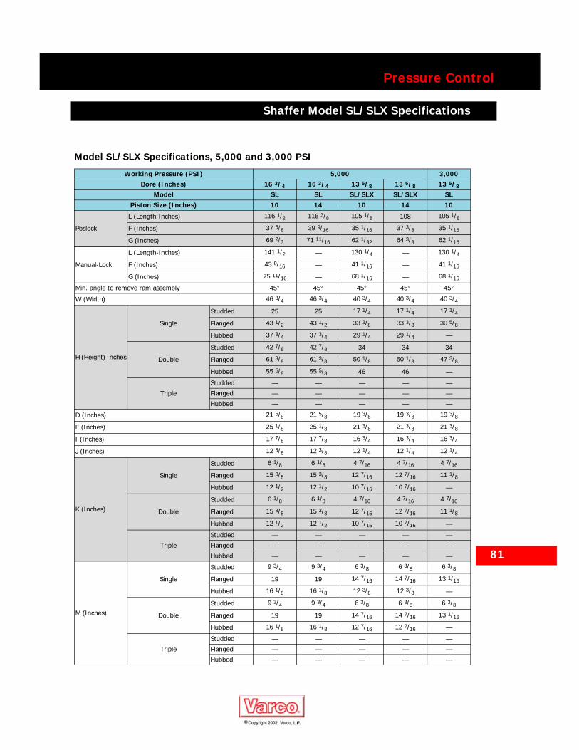
Model SL/SLX Specifications, 5,000 and 3,000 PSI
Working Pressure (PSI) 5,000 3,000Bore (Inches) 16 3/4 16 3/4 13 5/8 13 5/8 13 5/8
Model SL SL SL/SLX SL/SLX SLPiston Size (Inches) 10 14 10 14 10
Poslock
L (Length-Inches) 116 1/2 118 3/8 105 1/8 108 105 1/8
F (Inches) 37 5/8 39 9/16 35 1/16 37 3/8 35 1/16
G (Inches) 69 2/3 71 11/16 62 1/32 64 3/8 62 1/16
Manual-Lock
L (Length-Inches) 141 1/2 — 130 1/4 — 130 1/4
F (Inches) 43 9/16 — 41 1/16 — 41 1/16
G (Inches) 75 11/16 — 68 1/16 — 68 1/16
Min. angle to remove ram assembly 45° 45° 45° 45° 45°
W (Width) 46 3/4 46 3/4 40 3/4 40 3/4 40 3/4
H (Height) Inches
Single
Studded 25 25 17 1/4 17 1/4 17 1/4
Flanged 43 1/2 43 1/2 33 3/8 33 3/8 30 5/8
Hubbed 37 3/4 37 3/4 29 1/4 29 1/4 —
Double
Studded 42 7/8 42 7/8 34 34 34
Flanged 61 3/8 61 3/8 50 1/8 50 1/8 47 3/8
Hubbed 55 5/8 55 5/8 46 46 —
Triple
Studded — — — — —
Flanged — — — — —
Hubbed — — — — —
D (Inches) 21 5/8 21 5/8 19 3/8 19 3/8 19 3/8
E (Inches) 25 1/8 25 1/8 21 3/8 21 3/8 21 3/8
I (Inches) 17 7/8 17 7/8 16 3/4 16 3/4 16 3/4
J (Inches) 12 3/8 12 3/8 12 1/4 12 1/4 12 1/4
K (Inches)
Single
Studded 6 1/8 6 1/8 4 7/16 4 7/16 4 7/16
Flanged 15 3/8 15 3/8 12 7/16 12 7/16 11 1/8
Hubbed 12 1/2 12 1/2 10 7/16 10 7/16 —
Double
Studded 6 1/8 6 1/8 4 7/16 4 7/16 4 7/16
Flanged 15 3/8 15 3/8 12 7/16 12 7/16 11 1/8
Hubbed 12 1/2 12 1/2 10 7/16 10 7/16 —
Triple
Studded — — — — —
Flanged — — — — —
Hubbed — — — — —
M (Inches)
Single
Studded 9 3/4 9 3/4 6 3/8 6 3/8 6 3/8
Flanged 19 19 14 7/16 14 7/16 13 1/16
Hubbed 16 1/8 16 1/8 12 3/8 12 3/8 —
Double
Studded 9 3/4 9 3/4 6 3/8 6 3/8 6 3/8
Flanged 19 19 14 7/16 14 7/16 13 1/16
Hubbed 16 1/8 16 1/8 12 7/16 12 7/16 —
Triple
Studded — — — — —
Flanged — — — — —
Hubbed — — — — —
82
Pressure Control
Shaffer Model SL/SLX Specifications
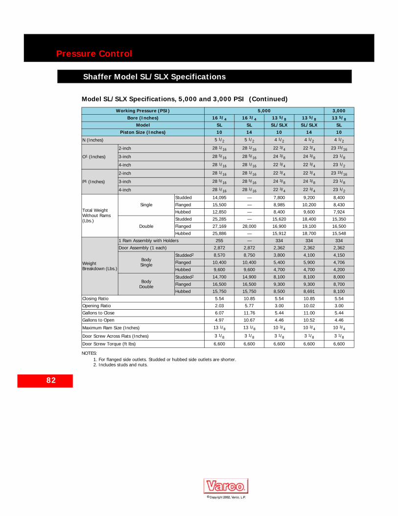
N (Inches) 5 1/2 5 1/2 4 1/2 4 1/2 4 1/2
O1 (Inches)
2-inch 28 1/16 28 1/16 22 3/4 22 3/4 23 15/16
3-inch 28 5/16 28 5/16 24 3/8 24 3/8 23 1/8
4-inch 28 1/16 28 1/16 22 3/4 22 3/4 23 1/2
P1 (Inches)
2-inch 28 1/16 28 1/16 22 3/4 22 3/4 23 15/16
3-inch 28 5/16 28 5/16 24 3/8 24 3/8 23 1/8
4-inch 28 1/16 28 1/16 22 3/4 22 3/4 23 1/2
Total Weight Without Rams (Lbs.)
Single
Studded 14,095 — 7,800 9,200 8,400
Flanged 15,500 — 8,985 10,200 8,430
Hubbed 12,850 — 8,400 9,600 7,924
Double
Studded 25,285 — 15,620 18,400 15,350
Flanged 27,169 28,000 16,900 19,100 16,500
Hubbed 25,886 — 15,912 18,700 15,548
Weight Breakdown (Lbs.)
1 Ram Assembly with Holders 255 — 334 334 334
Door Assembly (1 each) 2,872 2,872 2,362 2,362 2,362
BodySingle
Studded2 8,570 8,750 3,800 4,100 4,150
Flanged 10,400 10,400 5,400 5,900 4,706
Hubbed 9,600 9,600 4,700 4,700 4,200
BodyDouble
Studded2 14,700 14,900 8,100 8,100 8,000
Flanged 16,500 16,500 9,300 9,300 8,700
Hubbed 15,750 15,750 8,500 8,691 8,100
Closing Ratio 5.54 10.85 5.54 10.85 5.54
Opening Ratio 2.03 5.77 3.00 10.02 3.00
Gallons to Close 6.07 11.76 5.44 11.00 5.44
Gallons to Open 4.97 10.67 4.46 10.52 4.46
Maximum Ram Size (Inches) 13 1/8 13 1/8 10 3/4 10 3/4 10 3/4
Door Screw Across Flats (Inches) 3 1/8 3 1/8 3 1/8 3 1/8 3 1/8Door Screw Torque (ft lbs) 6,600 6,600 6,600 6,600 6,600
NOTES:1. For flanged side outlets. Studded or hubbed side outlets are shorter.2. Includes studs and nuts.
Model SL/SLX Specifications, 5,000 and 3,000 PSI (Continued)
Working Pressure (PSI) 5,000 3,000Bore (Inches) 16 3/4 16 3/4 13 5/8 13 5/8 13 5/8
Model SL SL SL/SLX SL/SLX SLPiston Size (Inches) 10 14 10 14 10
83
Pressure Control
Shaffer Model SL/SLX Specifications
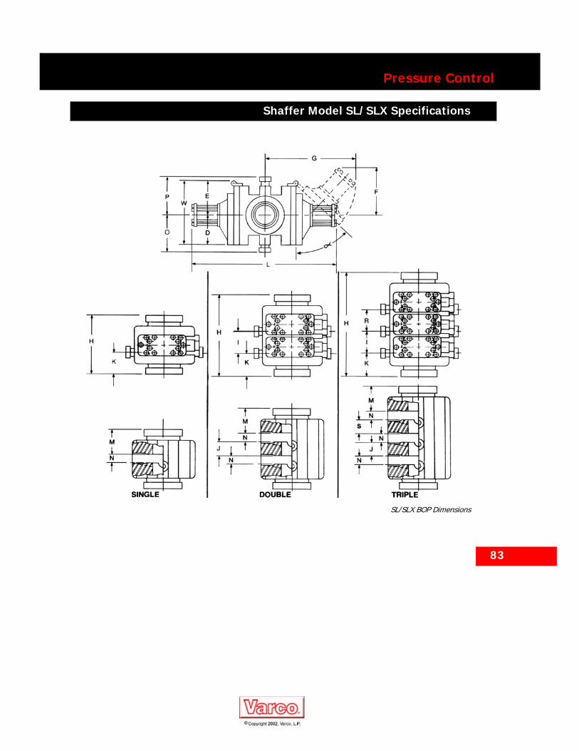
SL/SLX BOP Dimensions

84
Pressure Control
Shaffer Model LWS Specifications
Shaffer Model LWS Specifications
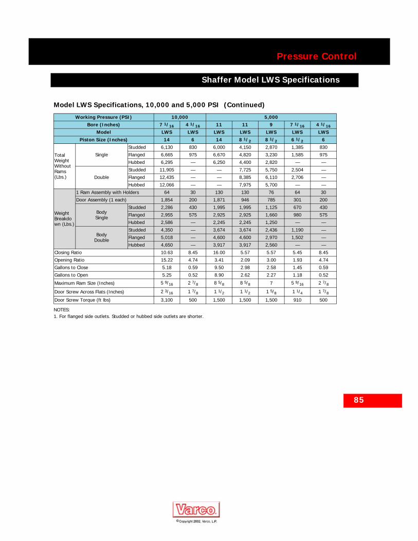
Model LWS Specifications, 10,000 and 5,000 PSI
Working Pressure (PSI) 10,000 5,000Bore (Inches) 7 1/16 4 1/16 11 11 9 7 1/16 4 1/16
Model LWS LWS LWS LWS LWS LWS LWSPiston Size (Inches) 14 6 14 8 1/2 8 1/2 6 1/2 6
Poslock
L (Length-Inches) — — 10 1/4 — — — —
F (Inches) — — 37 7/8 — — — —
G (Inches) — — 57 — — — —
Manual-Lock
L (Length-Inches) 74 3/4 42 1/4 — 89 1/4 79 1/8 58 1/4 42 1/4
F (Inches) 26 3/4 14 1/8 — 29 3/8 27 7/16 20 3/8 14 1/8
G (Inches) 43 3/8 23 13/16 — 46 5/8 46 5/16 32 1/2 23 13/16
W (Width) 30 7/8 15 3/8 28 3/4 28 3/4 23 1/16 21 1/2 15 11/16
H (Height) Inches
Single
Studded 23 3/4 15 3/4 19 1/2 19 1/2 14 1/2 15 15 3/4
Flanged 39 7/8 20 3/4 37 37 30 1/8 28 1/4 20 3/4
Hubbed — — 30 1/16 30 1/16 22 — —
Double
Studded 43 1/2 — 33 33 29 1/2 26 3/4 —
Flanged 59 5/8 — 50 1/2 50 1/2 45 7/16 40 —
Hubbed — — 43 9/16 43 9/16 37 — —
D (Inches) 13 3/8 6 7/16 12 5/8 12 5/8 11 9 3/16 6 7/16
E (Inches) 17 1/2 8 15/16 16 1/8 16 1/8 12 1/16 12 5/16 9 1/4
I (Inches) 21 3/4 — 15 1/2 15 1/2 15 11 3/4 —
J (Inches) 17 1/4 — 11 11 10 1/2 7 1/4 —
K (Inches)
Single
Studded 7 1/8 — 5 1/2 5 1/2 3 1/4 3 3/4 —
Flanged 15 3/16 7 1/8 14 1/4 14 1/4 11 1/16 10 3/8 —
Hubbed — — 10 25/32 10 25/32 7 — —
Double
Studded 6 1/8 — 4 1/2 4 1/2 3 1/4 3 3/4 —
Flanged 14 3/16 7 1/8 13 1/4 13 1/4 11 1/4 10 3/8 7 1/8
Hubbed — — 9 25/32 9 25/32 7 — —
M (Inches)
Single
Studded 9 5/8 5 7/16 7 7 5 5 3 7/8
Flanged 17 3/4 8 7/8 15 3/4 15 3/4 12 3/16 11 5/8 8 7/8
Hubbed — — 12 9/32 12 9/32 8 3/4 — —
Double
Studded 8 5/8 — 6 6 5 5 —
Flanged 16 3/4 — 14 3/4 14 3/4 12 13/16 11 5/8 —
Hubbed — — 11 9/32 11 9/32 8 3/4 — —
N (Inches) 4 1/2 3 4 1/2 4 1/2 4 1/2 4 1/2 3
O1 (Inches)
2-inch 20 5/8 9 5/8 20 1/16 20 1/16 18 7/16 14 1/2 12 9/16
3-inch 21 13/16 — 21 11/16 21 11/16 20 1/16 14 3/4 —
4-inch 22 3/8 — 20 1/16 20 1/16 — 14 1/2 —
P1
(Inches)
2-inch 20 5/8 12 9/16 19 13/16 19 13/16 18 7/16 15 1/16 9 5/8
3-inch 21 13/16 — 21 7/16 21 7/16 20 1/16 16 1/16 —
4-inch 22 3/8 — 19 13/16 19 13/16 — 18 7/8 —
85
Pressure Control
Shaffer Model LWS Specifications
Total Weight Without Rams (Lbs.)
Single
Studded 6,130 830 6,000 4,150 2,870 1,385 830
Flanged 6,665 975 6,670 4,820 3,230 1,585 975
Hubbed 6,295 — 6,250 4,400 2,820 — —
Double
Studded 11,905 — — 7,725 5,750 2,504 —
Flanged 12,435 — — 8,385 6,110 2,706 —
Hubbed 12,066 — — 7,975 5,700 — —
Weight Breakdown (Lbs.)
1 Ram Assembly with Holders 64 30 130 130 76 64 30
Door Assembly (1 each) 1,854 200 1,871 946 785 301 200
BodySingle
Studded 2,286 430 1,995 1,995 1,125 670 430
Flanged 2,955 575 2,925 2,925 1,660 980 575
Hubbed 2,586 — 2,245 2,245 1,250 — —
BodyDouble
Studded 4,350 — 3,674 3,674 2,436 1,190 —
Flanged 5,018 — 4,600 4,600 2,970 1,502 —
Hubbed 4,650 — 3,917 3,917 2,560 — —
Closing Ratio 10.63 8.45 16.00 5.57 5.57 5.45 8.45
Opening Ratio 15.22 4.74 3.41 2.09 3.00 1.93 4.74
Gallons to Close 5.18 0.59 9.50 2.98 2.58 1.45 0.59
Gallons to Open 5.25 0.52 8.90 2.62 2.27 1.18 0.52
Maximum Ram Size (Inches) 5 9/16 2 7/8 8 5/8 8 5/8 7 5 9/16 2 7/8
Door Screw Across Flats (Inches) 2 3/16 1 7/8 1 1/2 1 1/2 1 5/8 1 1/4 1 7/8Door Screw Torque (ft lbs) 3,100 500 1,500 1,500 1,500 910 500
NOTES:1. For flanged side outlets. Studded or hubbed side outlets are shorter.
Model LWS Specifications, 10,000 and 5,000 PSI (Continued)
Working Pressure (PSI) 10,000 5,000Bore (Inches) 7 1/16 4 1/16 11 11 9 7 1/16 4 1/16
Model LWS LWS LWS LWS LWS LWS LWSPiston Size (Inches) 14 6 14 8 1/2 8 1/2 6 1/2 6

86
Pressure Control
Shaffer Model LWS Specifications
Model LWS Specifications, 3,000 and 2,000 PSI
Working Pressure (PSI) 3,000 2,000Bore (Inches) 20 3/4 20 3/4 20 3/4 11 21 1/4 21 1/4 21 1/4
Model LWS LWS LWS LWS LWS LWS LWSPiston Size (Inches) 10 14 8 1/2 6 1/2 10 14 8 1/2
Poslock
L (Length-Inches) 117 1/8 132 1/8 — — 117 1/4 132 1/4 —
F (Inches) 41 3/8 48 — — 41 3/8 48 —
G (Inches) 67 7/8 73 3/8 — — 67 75 1/8 —
Manual-Lock
L (Length-Inches) — 161 3/4 127 1/2 72 5/8 — 161 3/4 127 1/2
F (Inches) — 54 5/16 42 23 15/16 — 54 5/16 42
G (Inches) — 79 15/16 67 5/8 39 31/32 — 79 15/16 67 5/8
W (Width) 41 1/4 41 1/4 41 1/4 25 15/16 40 7/8 40 7/8 40 7/8
H (Height) Inches
Single
Studded 23 1/8 23 1/8 23 1/8 14 1/2 23 1/8 23 1/8 23 1/8
Flanged 41 5/8 41 5/8 41 5/8 27 1/8 37 3/4 37 3/4 37 3/4
Hubbed 35 3/8 35 3/8 35 3/8 22 34 5/8 34 5/8 34 5/8
Double
Studded 49 1/4 49 1/4 49 1/4 29 3/8 49 1/4 49 1/4 44 7/16
Flanged 67 3/4 63 63 42 63 7/8 59 1/16 59 1/16
Hubbed 62 55 15/16 49 1/4 36 7/8 57 60 3/4 55 15/16
D (Inches) 17 3/8 17 3/8 17 3/8 11 9/16 17 1/4 17 1/4 17 1/4
E (Inches) 23 5/8 23 5/8 23 5/8 14 3/8 23 5/8 23 5/8 23 5/8
I (Inches) 26 1/2 21 5/16 21 5/16 14 26 1/8 26 1/8 21 5/16
J (Inches) 20 1/8 20 1/8 20 1/8 9 1/2 20 1/8 20 1/8 15 5/16
K (Inches)
Single
Studded 6 6 6 3 7/8 6 6 6
Flanged 15 1/4 15 1/4 15 1/4 10 3/16 13 5/16 13 5/16 13 5/16
Hubbed — — — 7 5/8 11 3/4 11 3/4 11 3/4
Double
Studded 6 6 6 4 5/16 6 6 6
Flanged 15 1/4 15 1/4 15 1/4 10 5/8 13 5/16 13 5/16 13 5/16
Hubbed — 11 3/4 13 8 1/16 11 3/4 11 3/4 11 3/4
M (Inches)
Single
Studded 7 1/8 7 1/8 7 1/8 4 3/8 7 1/8 7 1/8 7 1/8
Flanged 16 3/8 16 3/8 16 3/8 10 11/16 14 7/16 14 7/16 14 7/16
Hubbed — — — 8 1/8 12 7/8 12 7/8 12 7/8
Double
Studded — — — 4 13/16 7 1/8 7 1/8 7 1/8
Flanged 16 3/8 16 3/8 16 3/8 11 3/16 14 7/16 14 7/16 14 7/16
Hubbed — — — 8 9/16 12 7/8 12 7/8 12 7/8
N (Inches) 7 7 7 4 1/2 6 6 6
O1
(Inches)
2-inch 25 7/8 25 7/8 25 7/8 16 3/4 25 7/8 25 7/8 25 7/8
3-inch 25 1/16 25 1/16 26 5/16 15 3/4 26 5/16 26 5/16 26 5/16
4-inch 25 7/16 25 7/16 25 7/16 16 1/8 25 7/16 25 7/16 25 7/16
P1
(Inches)
2-inch 25 7/8 25 7/8 25 7/8 17 3/16 25 7/8 25 7/8 25 7/8
3-inch 25 1/16 25 1/16 26 5/16 17 3/16 26 5/16 26 5/16 26 5/16
4-inch 25 7/16 28 3/8 25 7/16 18 25 7/16 25 7/16 25 7/16

87
Pressure Control
Shaffer Model LWS Specifications
Total Weight Without Rams (Lb)
Single
Studded 7,810 10,068 7,448 2,116 7,647 9,905 7,285
Flanged 8,912 11,170 8,550 2,580 8,347 10,605 7,985
Hubbed 7,537 9,795 7,175 2,150 7,774 10,032 7,412
Double
Studded 15,338 19,854 14,615 4,096 15,180 19,700 14,455
Flanged 16,440 20,955 15,715 4,560 15,880 20,400 15,155
Hubbed 15,062 19,580 14,340 4,130 15,305 19,822 14,582
Weight Breakdown (Lb)
1 Ram Assembly with Holders 435 435 435 111 435 435 435
Door Assembly (1 each) 1,756 2,885 1,575 490 1,756 2,885 1,575
BodySingle
Studded 3,760 3,760 3,760 1,000 3,790 3,790 3,790
Flanged 5,400 5,400 5,400 1,600 4,835 4,835 4,835
Hubbed 4,025 4,025 4,025 1,170 4,262 4,262 4,262
BodyDouble
Studded 7,776 7,776 7,776 2,000 7,810 7,810 7,810
Flanged 9,415 9,415 9,415 2,600 8,855 8,855 8,855
Hubbed 8,038 8,038 8,038 2,170 8,281 8,281 8,281
Closing Ratio 8.16 16.00 5.57 5.45 8.16 16.00 5.57
Opening Ratio 1.15 2.21 0.78 1.16 1.15 2.21 0.78
Gallons to Close 7.80 14.50 5.07 1.74 7.80 14.50 5.07
Gallons to Open 6.86 13.59 4.46 1.45 6.86 13.59 4.46
Maximum Ram Size (Inches) 16 16 16 8 5/8 16 16 16
Door Screw Across Flats (Inches) 1 5/8 1 5/8 1 5/8 1 1/4 1 5/8 1 5/8 1 5/8Door Screw Torque (ft lb) 1,200 1,200 1,200 910 1,200 1,200 1,200
NOTES:
1. For flanged side outlets. Studded or hubbed side outlets are shorter.
Model LWS Specifications, 3,000 and 2,000 PSI (Continued)
Working Pressure (PSI) 3,000 2,000Bore (Inches) 20 3/4 20 3/4 20 3/4 11 21 1/4 21 1/4 21 1/4
Model LWS LWS LWS LWS LWS LWS LWSPiston Size (Inches) 10 14 8 1/2 6 1/2 10 14 8 1/2
88
Pressure Control
Shaffer Model LWS Specifications
Shaffer Model LWS Specifications
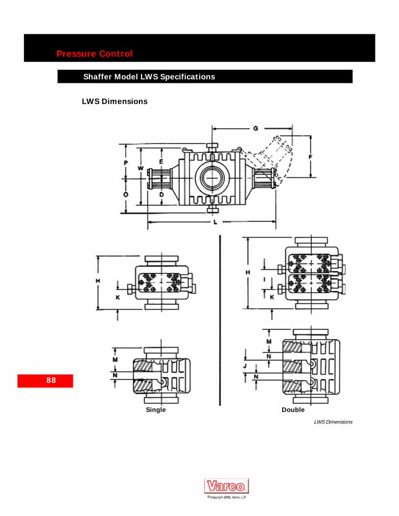
LWS Dimensions
LWS Dimensions
Single Double
89
Pressure Control
Shaffer Model Chasovoy Specifications
Shaffer Model Chasovoy Specifications
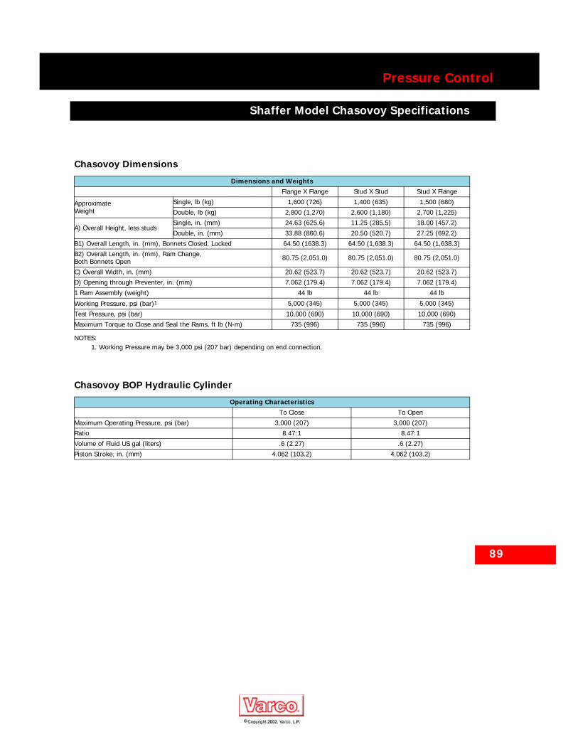
Chasovoy Dimensions
Dimensions and WeightsFlange X Flange Stud X Stud Stud X Flange
ApproximateWeight
Single, lb (kg) 1,600 (726) 1,400 (635) 1,500 (680)
Double, lb (kg) 2,800 (1,270) 2,600 (1,180) 2,700 (1,225)
A) Overall Height, less studsSingle, in. (mm) 24.63 (625.6) 11.25 (285.5) 18.00 (457.2)
Double, in. (mm) 33.88 (860.6) 20.50 (520.7) 27.25 (692.2)
B1) Overall Length, in. (mm), Bonnets Closed, Locked 64.50 (1638.3) 64.50 (1,638.3) 64.50 (1,638.3)
B2) Overall Length, in. (mm), Ram Change, Both Bonnets Open 80.75 (2,051.0) 80.75 (2,051.0) 80.75 (2,051.0)
C) Overall Width, in. (mm) 20.62 (523.7) 20.62 (523.7) 20.62 (523.7)
D) Opening through Preventer, in. (mm) 7.062 (179.4) 7.062 (179.4) 7.062 (179.4)
1 Ram Assembly (weight) 44 lb 44 lb 44 lb
Working Pressure, psi (bar)1
NOTES:1. Working Pressure may be 3,000 psi (207 bar) depending on end connection.
5,000 (345) 5,000 (345) 5,000 (345)
Test Pressure, psi (bar) 10,000 (690) 10,000 (690) 10,000 (690)
Maximum Torque to Close and Seal the Rams, ft lb (N-m) 735 (996) 735 (996) 735 (996)
Chasovoy BOP Hydraulic Cylinder
Operating CharacteristicsTo Close To Open
Maximum Operating Pressure, psi (bar) 3,000 (207) 3,000 (207)
Ratio 8.47:1 8.47:1
Volume of Fluid US gal (liters) .6 (2.27) .6 (2.27)
Piston Stroke, in. (mm) 4.062 (103.2) 4.062 (103.2)

90
Pressure Control
Shaffer Chasovoy BOP Dimensions
Shaffer Chasovoy BOP Dimensions
Chasovoy BOP Dimensions
Chasovoy BOP Dimensions
91
Pressure Control
Shaffer Ram BOP Ordering Information
Shaffer Ram BOP Ordering Information
OrderingWhen ordering Shaffer ram BOPs, specify the following:
1. Locking System required — UltraLock™, Poslock or Manual Lock.
2. Single, double or triple.3. Bore size, working pressure,
connections (studded, flanged or hubbed) and ring grooves. API ring grooves will be supplied, unless otherwise specified.
4. Side outlets required:a. Size, working pressure, type
(studded, flanged or hubbed) andring grooves. API ring grooveswill be supplied, unless otherwisespecified.
b. Locations:■ Below which ram(s).■ Front and/or back (hinge side).
5. Rams to be furnished.a. Type:
■ Blind (complete shut-off).■ Pipe or casing size rams.■ Shear requirements.
b. Location of each set of rams.6. Special features available:
a. Stainless steel or inconel lined ringgrooves.
b. For low temperature certification(below -20° F), advise yourShaffer sales representative ofyour requirements.
c. Full environmental H2S (internalH2S trim standard).
d. The no-weld cavity is standard onthe NXT ram BOP, an availableoption on the SLX ram BOP, andavailable as retrofit on some SLram BOP sizes.
92
Pressure Control
Shaffer SL/SLX BOP Pipe Rams
Shaffer SL/SLX BOP Pipe Rams
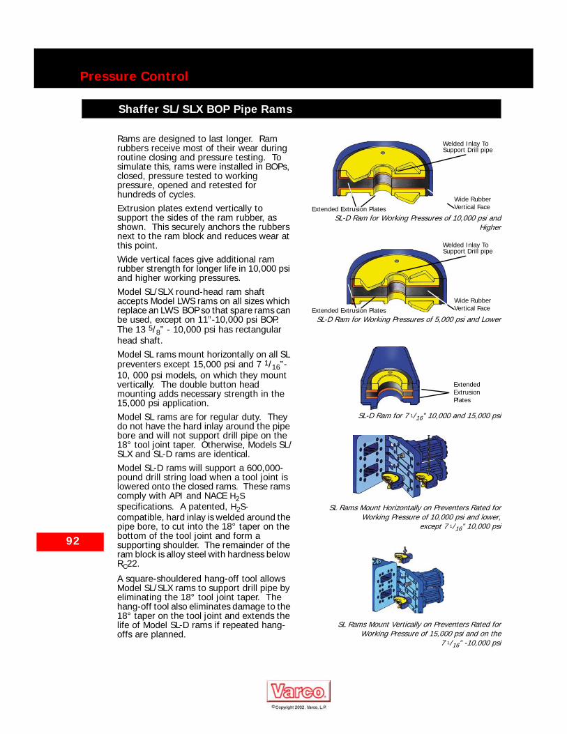
Rams are designed to last longer. Ram rubbers receive most of their wear during routine closing and pressure testing. To simulate this, rams were installed in BOPs, closed, pressure tested to working pressure, opened and retested for hundreds of cycles. Extrusion plates extend vertically to support the sides of the ram rubber, as shown. This securely anchors the rubbers next to the ram block and reduces wear at this point.Wide vertical faces give additional ram rubber strength for longer life in 10,000 psi and higher working pressures.Model SL/SLX round-head ram shaft accepts Model LWS rams on all sizes which replace an LWS BOP so that spare rams can be used, except on 11”-10,000 psi BOP. The 13 5/8” - 10,000 psi has rectangular head shaft.Model SL rams mount horizontally on all SL preventers except 15,000 psi and 7 1/16”-10, 000 psi models, on which they mount vertically. The double button head mounting adds necessary strength in the 15,000 psi application.Model SL rams are for regular duty. They do not have the hard inlay around the pipe bore and will not support drill pipe on the 18° tool joint taper. Otherwise, Models SL/SLX and SL-D rams are identical.Model SL-D rams will support a 600,000-pound drill string load when a tool joint is lowered onto the closed rams. These rams comply with API and NACE H2S specifications. A patented, H2S-compatible, hard inlay is welded around the pipe bore, to cut into the 18° taper on the bottom of the tool joint and form a supporting shoulder. The remainder of the ram block is alloy steel with hardness below RC22.
A square-shouldered hang-off tool allows Model SL/SLX rams to support drill pipe by eliminating the 18° tool joint taper. The hang-off tool also eliminates damage to the 18° taper on the tool joint and extends the life of Model SL-D rams if repeated hang-offs are planned.
SL-D Ram for Working Pressures of 10,000 psi andHigher
SL-D Ram for Working Pressures of 5,000 psi and Lower
SL-D Ram for 7 1/16” 10,000 and 15,000 psi
SL Rams Mount Horizontally on Preventers Rated forWorking Pressure of 10,000 psi and lower,
except 7 1/16” 10,000 psi
SL Rams Mount Vertically on Preventers Rated forWorking Pressure of 15,000 psi and on the
7 1/16” -10,000 psi
Welded Inlay To
Extended Extrusion PlatesWide Rubber
Support Drill pipe
Vertical Face
Welded Inlay To Support Drill pipe
Extended Extrusion PlatesWide Rubber Vertical Face
Extended Extrusion Plates
93
Pressure Control
Shaffer SL/SLX BOP Pipe Rams
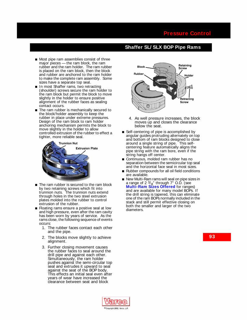
■ Most pipe ram assemblies consist of three major pieces — the ram block, the ram rubber and the ram holder. The ram rubber is placed on the ram block, then the block and rubber are anchored to the ram holder to make the complete ram assembly. Some sizes have a separate top seal.
■ In most Shaffer rams, two retracting (shoulder) screws secure the ram holder to the ram block but permit the block to move slightly in the holder to ensure positive alignment of the rubber faces as sealing contact occurs.
■ The ram rubber is mechanically secured to the block/holder assembly to keep the rubber in place under extreme pressures. Design of the ram block to ram holder anchoring mechanism permits the block to move slightly in the holder to allow controlled extrusion of the rubber to effect a tighter, more reliable seal.
■ The ram rubber is secured to the ram block by two retaining screws which fit into trunnion nuts. The trunnion nuts extend through holes in the two steel extrusion plates molded into the rubber to control extrusion of the rubber.
■ Floating rams ensure a positive seal at low and high pressure, even after the ram cavity has been worn by years of service. As the rams close, the following sequence of events occurs:
1. The rubber faces contact each otherand the pipe.
2. The blocks move slightly to achievealignment.
3. Further closing movement causesthe rubber faces to seal around thedrill pipe and against each other. Simultaneously, the ram holderpushes against the semi-circular topseal and extrudes it upward to sealagainst the seat of the BOP body.This effects an initial seal even afteryears of wear have increased theclearance between seat and block
4. As well pressure increases, the blockmoves up and closes the clearancebelow the seat.
■ Self-centering of pipe is accomplished by angular guides protruding alternately on top and bottom of ram blocks designed to close around a single string of pipe. This self-centering feature automatically aligns the pipe string with the ram bore, even if the string hangs off center.
■ Continuous, molded ram rubber has no separation between the semicircular top seal and the horizontal face seal in most sizes.
■ Rubber compounds for all oil field conditions are available.
■ New Multi-Ram rams will seal on pipe sizes in a range of 2 3/8” through 7” O.D. (see Multi-Ram Sizes Offered for ranges) and are available for many model BOPs. If the drill string is tapered, this can eliminate one of the ram BOPs normally included in the stack and still permit effective closing on both the smaller and larger of the two diameters.
94
Pressure Control
Shaffer Model NXT and Ultra Temp Pipe Rams
Shaffer Model NXT and Ultra Temp Pipe Rams
For part numbers, contact your local Shaffer representative.
For part numbers, contact your local Shaffer representative.
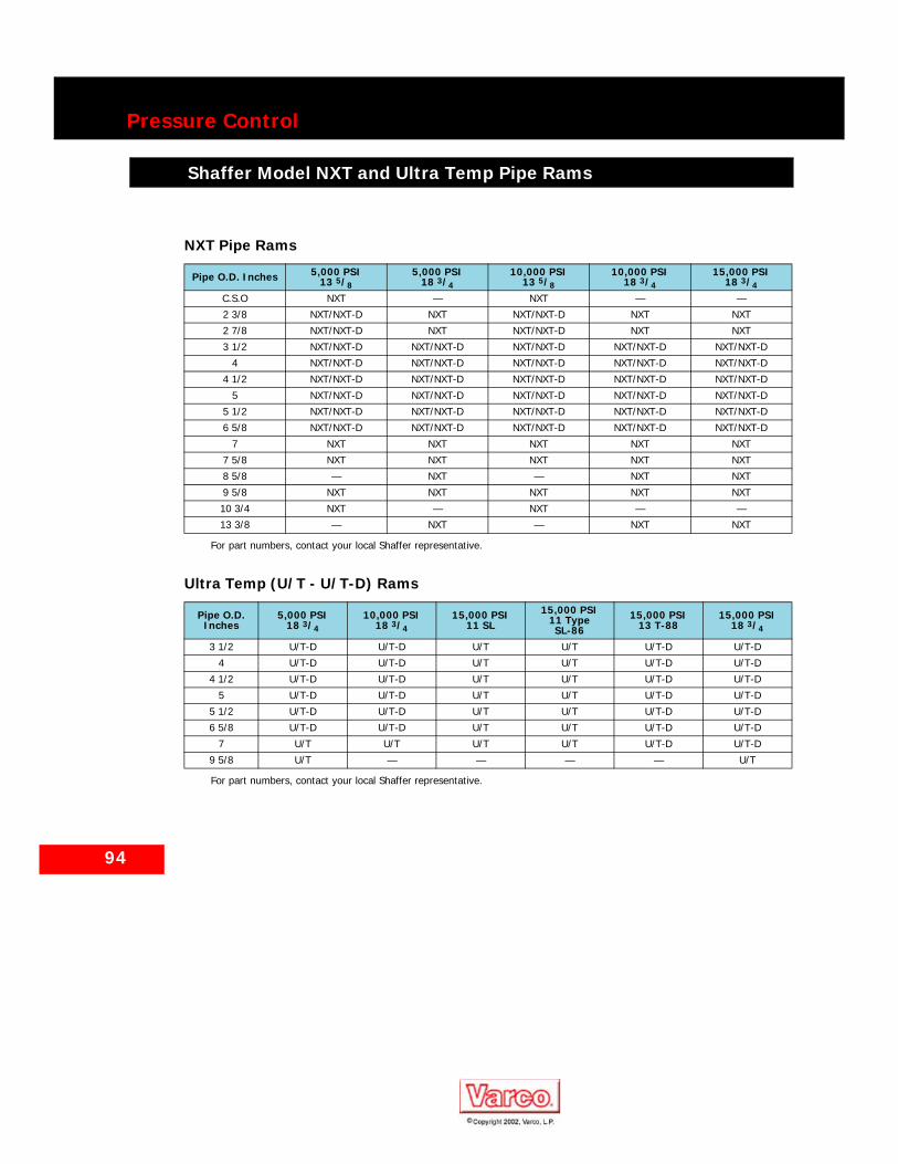
NXT Pipe Rams
Pipe O.D. Inches 5,000 PSI 13 5/8
5,000 PSI 18 3/4
10,000 PSI 13 5/8
10,000 PSI 18 3/4
15,000 PSI 18 3/4
C.S.O NXT — NXT — —
2 3/8 NXT/NXT-D NXT NXT/NXT-D NXT NXT
2 7/8 NXT/NXT-D NXT NXT/NXT-D NXT NXT
3 1/2 NXT/NXT-D NXT/NXT-D NXT/NXT-D NXT/NXT-D NXT/NXT-D
4 NXT/NXT-D NXT/NXT-D NXT/NXT-D NXT/NXT-D NXT/NXT-D
4 1/2 NXT/NXT-D NXT/NXT-D NXT/NXT-D NXT/NXT-D NXT/NXT-D
5 NXT/NXT-D NXT/NXT-D NXT/NXT-D NXT/NXT-D NXT/NXT-D
5 1/2 NXT/NXT-D NXT/NXT-D NXT/NXT-D NXT/NXT-D NXT/NXT-D
6 5/8 NXT/NXT-D NXT/NXT-D NXT/NXT-D NXT/NXT-D NXT/NXT-D
7 NXT NXT NXT NXT NXT
7 5/8 NXT NXT NXT NXT NXT
8 5/8 — NXT — NXT NXT
9 5/8 NXT NXT NXT NXT NXT
10 3/4 NXT — NXT — —
13 3/8 — NXT — NXT NXT
Ultra Temp (U/T - U/T-D) Rams
Pipe O.D. Inches
5,000 PSI18 3/4
10,000 PSI18 3/4
15,000 PSI 11 SL
15,000 PSI11 Type SL-86
15,000 PSI13 T-88
15,000 PSI 18 3/4
3 1/2 U/T-D U/T-D U/T U/T U/T-D U/T-D
4 U/T-D U/T-D U/T U/T U/T-D U/T-D
4 1/2 U/T-D U/T-D U/T U/T U/T-D U/T-D
5 U/T-D U/T-D U/T U/T U/T-D U/T-D
5 1/2 U/T-D U/T-D U/T U/T U/T-D U/T-D
6 5/8 U/T-D U/T-D U/T U/T U/T-D U/T-D
7 U/T U/T U/T U/T U/T-D U/T-D
9 5/8 U/T — — — — U/T

95
Pressure Control
Shaffer Model SL/SLX Pipe Rams
Shaffer Model SL/SLX Pipe Rams
For part numbers, contact your local Shaffer representative.
Model SL/SLX Pipe Rams
Pipe O.D.
Inches
3,000 PSI 5,000 PSI 10,000 PSI 15,000 PSI
13 5/8 13 5/8 16 3/4 7 1/16 11 13 5/8 16 3/4 18 3/4 21 1/4 7 1/16 11 13 5/8 18 3/4
C.S.O SL SL SL SL SL SL SL SL SL SL SLSL, SLX ,
SL-D, SLX-D
SL
7/16 SL SL — — — — — — — — — — —1.315 SL SL SL SL SL SL SL — — SL SL SL —1.660 SL SL SL SL SL SL SL — — SL SL SL —1.900 SL SL SL SL SL SL SL — — SL SL SL —2 1/16 SL SL — SL — — — — — SL — — —2 3/8 SL SL SL SL SL SL SL SL SL SL SL SL/SLX SL2 7/8 SL SL SL SL SL SL SL SL SL SL SL SL/SLX SL
3 1/2SL or SL-D
SL or SL-D
SL or SL-D
SL or SL-D SL-D SL or
SL-DSL or SL-D
SL or SL-D
SL or SL-D SL SL or
SL-D
SL, SLX , SL-D, SLX-D
SL or SL-D
3 5/8SL or SL-D
SL or SL-D — — — — — — — — — — —
4 SL or SL-D
SL or SL-D
SL or SL-D
SL or SL-D SL-D SL or
SL-DSL or SL-D
SL or SL-D
SL or SL-D SL SL or
SL-D
SL, SLX , SL-D, SLX-D
SL or SL-D
4 1/8SL or SL-D
SL or SL-D — — — — — — — — — — —
4.200 SL or SL-D
SL orSL-D — — — — — — — — — — —
4 1/2SL or SL-D
SL or SL-D
SL or SL-D
SL or SL-D SL-D SL or
SL-DSL or SL-D
SL or SL-D
SL or SL-D SL SL or
SL-D
SL, SLX, SL-D, SLX-D
SL or SL-D
4 5/8SL or SL-D
SL or SL-D — SL or
SL-D SL-D SL or SL-D — — — — — — —
5 SL or SL-D
SL or SL-D
SL or SL-D
SL or SL-D SL-D SL or
SL-DSL or SL-D
SL or SL-D
SL orSL-D SL SL or
SL-D
SL, SLX , SL-D, SLX-D
SL or SL-D
5 1/2SL or SL-D
SL or SL-D
SL or SL-D
SL or SL-D SL-D SL or
SL-DSL or SL-D
SL or SL-D
SL orSL-D SL SL or
SL-D
SL, SLX , SL-D, SLX-D
SL or SL-D
5 9/16SL or SL-D
SL or SL-D — — — — — — — — — — —
6 — — — — — SL — — — — — — —6 1/2 SL SL — — — — — — — — — — —
6 5/8 SL SL SL — SL SL SL SL or SL-D SL — SL
SL, SLX , SL-D, SLX-D
SL
7 SL SL SL — SL SL SL SL SL — SL SL/SLX SL7 5/8 SL SL SL — SL SL SL SL SL — SL SL/SLX SL7 3/4 — — — — — SL — — — — — — —8 5/8 SL SL SL — SL SL SL SL SL — SL SL/SLX SL9 5/8 SL SL SL — — SL SL SL SL — — SL/SLX SL10 1/4 — — — — — — — — SL — — — —10 3/4 SL SL SL — — SL SL SL — — SL/SLX SL11 1/4 — — — — — — — SL — — — —11 3/4 — — SL — — — SL SL — — — — SL12 1/4 — — — — — — — SL — — — —13 3/8 — — SL — — — SL SL SL — — — SL
16 — — — — — — — SL SL — — — —18 1/8 — — — — — — — — SL — — — —

96
Pressure Control
Shaffer Chasovoy and LWS Pipe Rams
Shaffer Chasovoy and LWS Pipe Rams
For part numbers, contact your local Shaffer representative.
For part numbers, contact your local Shaffer representative.
Chasovoy Pipe Rams
3,000 PSI 3,000 PSI 3,000 PSI 3,000 PSI 5,000 PSI 5,000 PSI 5,000 PSI 5,000 PSI7 1/16” 180 mm 7 1/16” 180 mm 7 7/8” 200 mm
CSO CSO — — CSO CSO — —1 1/4” 32 mm — — 1 1/4” 32 mm — —
1.315” 33 mm — — 1.315” 33 mm — —1.660” 42 mm — — 1.660” 42 mm — —1.900” 48 mm — — 1.900” 48 mm — —2 1/16” 52 mm — — 2 1/16” 52 mm — —
2 3/8” 60 mm — — 2 3/8” 60 mm — —
2 7/8” 73 mm 2 7/8” 73 mm 2 7/8” 73 mm 2 7/8” 73 mm
3 1/2” 89 mm 3 1/2” 89 mm 3 1/2” 89 mm 3 1/2” 89 mm
4” 102 mm — — 4” 102 mm — —4 1/2” 114 mm 4 1/2” 144 mm 4 1/2” 114 mm 4 1/2” 144 mm
5” 127 mm — — 5” 127 mm — —5 1/2” 140 mm — — 5 1/2” 140 mm — —
— — 6 5/8” 168 mm — — 6 5/8” 168 mm
LWS Pipe Rams
Pipe O.D. Inches
2,000 PSI 3,000 PSI 5,000 PSI 10,000 PSI21 1/4 11 20 3/4 4 1/16 7 1/16 9 11 4 1/16 7 1/16
C.S.O 70-H 70-H 70-H 77 61 70-H 70-H 77 611.050 — — — — — — — 77 —1.315 — 70-H — 77 61 70-H 70-H 77 611.660 — 70-H — 77 61 70-H 70-H 77 611.900 — 70-H — 77 61 70-H 70-H 77 612 1/16 — 70-H — — 61 70-H 70-H — 612 3/8 70-H 70-H 70-H 77 61 70-H 70-H 77 612 7/8 70-H 70-H 70-H 77 61 70-H 70-H 77 613 1/2 73 70-H 73 — 61 70-H 70-H — 613.700 — — — — — — 70-H — —
4 73 70-H 73 — 61 70-H 70-H — 614 1/8 — 70-H — — — — 70-H — —4.200 — 70-H — — — — — — —4 1/2 73 70-H 73 — 61 70-H 70-H — 614 5/8 — 70-H — — — — — — —4 3/4 — 70-H — — 61 — — — 61
5 73 70-H 73 — 61 70-H 70-H — 615 1/2 73 70-H 73 — 61 70-H 70-H — 615 3/4 70-H — 70-H — — — — — —
6 70-H — 70-H — — — — — —6 5/8 70-H 70-H 70-H — — — 70-H — —
7 70-H 70-H 70-H — — — 70-H — —7 5/8 70-H 70-H 70-H — — — 70-H — —9 5/8 70-H — 70-H — — — — — —10 1/4 70-H — 70-H — — — — — —10 3/4 70-H — 70-H — — — — — —11 3/4 70-H — 70-H — — — — — —13 3/8 70-H — 70-H — — — — — —14 3/4 70-H — — — — — — — —
16 70-H — 70-H — — — — — —
97
Pressure Control
Shaffer Shear Rams
Shaffer Shear Rams
Type 72 Shear RamsThese rams shear pipe and seal the well bore in one operation. They also function as blind or CSO (complete shut-off) rams for normal operations.To ensure adequate shearing force, 14” pistons should be used when operating Type 72 shear rams. These pistons are standard in all BOPs rated at 10,000 psi working pressure and higher. On most lower pressure preventers, optional 14” pistons can be supplied for shearing instead of the standard 10” pistons. When shearing pipe in a subsea BOP stack, 3,000 psi closing pressure should be used.When shearing, the lower blade passes below the sharp lower edge of the upper ram block and shears the pipe. The lower section of cut pipe is accommodated in the space between the lower blade and the upper holder. The upper section of cut pipe is accommodated in the recess in the top of the lower ram block.Closing motion of the rams continues until the ram block ends meet. Continued closing of the holders squeezes the semicircular seals upward into sealing contact with the seat in the BOP body and energizes the horizontal seal. The closing motion of the upper holder pushes the horizontal seal forward and downward on top of the lower blade, resulting in a tight sealing contact. The horizontal seal has a molded-in support plate which holds it in place when the rams are open.The hydraulic closing pressure normally required to shear drill pipe is below 1,500 psi accumulator pressure in BOPs with 14” pistons. However, this varies, depending on the size, weight and grade of pipe. When shearing pipe in a subsea BOP stack, 3,000 psi closing pressure should be used. On 21 1/4” 2,000 psi and 11” 5,000 psi Model LWS BOPs, optional 14” pistons can be supplied for shearing instead of the standard 10” and 8 1/2” pistons.
Type V ShearThe Shaffer Type V Shear ram enhances the features of Shaffer’s T-72 shear ram by increasing the range of pipe that can be sheared without modification to the BOPs.
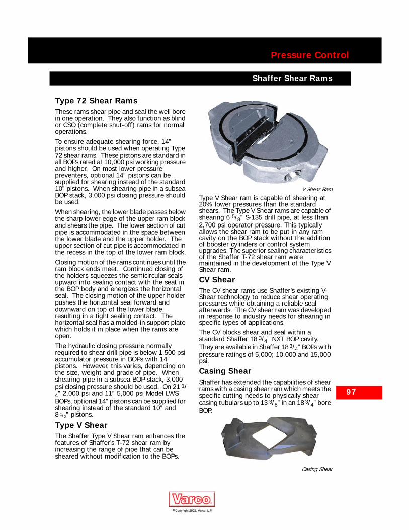
V Shear Ram
Type V Shear ram is capable of shearing at 20% lower pressures than the standard shears. The Type V Shear rams are capable of shearing 6 5/8” S-135 drill pipe, at less than 2,700 psi operator pressure. This typically allows the shear ram to be put in any ram cavity on the BOP stack without the addition of booster cylinders or control system upgrades. The superior sealing characteristics of the Shaffer T-72 shear ram were maintained in the development of the Type V Shear ram.
CV ShearThe CV shear rams use Shaffer’s existing V-Shear technology to reduce shear operating pressures while obtaining a reliable seal afterwards. The CV shear ram was developed in response to industry needs for shearing in specific types of applications. The CV blocks shear and seal within a standard Shaffer 18 3/4” NXT BOP cavity. They are available in Shaffer 18 3/4” BOPs with pressure ratings of 5,000; 10,000 and 15,000 psi.
Casing ShearShaffer has extended the capabilities of shear rams with a casing shear ram which meets the specific cutting needs to physically shear casing tubulars up to 13 3/8” in an 18 3/4” bore BOP.
Casing Shear

98
Pressure Control
Shaffer Multi-Rams
Shaffer Multi-Rams
Multi-RamsShaffer Multi-Rams can reduce stack height. One set of Multi-Rams closes to seal on pipe sizes ranging from 3 1/2” to 5 1/2” O.D. Rams need not be changed then when running a tapered drill string within this range. In many cases, it also is not necessary to add another ram BOP to the stack to accommodate drill string O.D. changes.Requirements from the U.S. Geological Survey in OCS Order No. 2 call for four ram BOPs and one annular BOP in the stack when using a tapered drill string. Two ram BOPs would be for the larger drill pipe, and one ram BOP would be for the smaller drill pipe. The fourth ram would contain a blind ram assembly. In the case of a subsea stack, the blind ram would be a blind/shear ram.The Shaffer Multi-Ram, however, can replace one of the large pipe rams and the small pipe ram — thus reducing the stack to three ram BOPs and one annular BOP. The major advantages are cost savings and the
reduction of stack height — especially important in view of height limitations on offshore structures.The Multi-Ram meets the USGC requirements for sealing capabilities around tapered drill string. A Shaffer ram BOP equipped with Multi-Rams counts as two ram BOPs — even though it is only one. The Multi-Rams can seal off on both the larger and the smaller drill strings.Shaffer Multi-Rams interchange with standard rams and with blind/shear rams. You simply open the BOP doors, remove the existing rams and install the Multi-Rams. The Multi-Rams use the same holder and retracting screws as the other ram assemblies. The only new parts are the ram block, top seal and the special packing assembly. When the Multi-Rams close on the drill string, there are steel segments molded into the ram rubbers which move radially inward, decreasing the bore size. Needless to say, substantial rig time is saved in not having to change ram assemblies to accommodate changes in drill pipe sizes.
Shaffer Multi-Rams
Closing Closed on 5 1/2” Pipe
Closed on 3 1/2” Pipe

99
Pressure Control
Shaffer Multi-Ram Sizes
Shaffer Multi-Ram Sizes
For part numbers, contact your local Shaffer representative.
Multi-Ram Sizes Offered
Bore Size (Inches) Working Pressure (PSI)
ModelPipe Size Range
(Inches)Pipe Suspension (000 lbs.)
2 3/8 2 7/8 3 1/2 4 4 1/2 5 5 1/2 6 5/8
7 1/16, 3,000 Sentinel 2 3/8 - 2 7/8 N/A N/A N/A N/A N/A N/A N/A N/A
7 1/16, 5,000 LWS 2 3/8 - 3 1/2 0 0 0 N/A N/A N/A N/A N/A
7 1/16, 10,000 SL 2 3/8 - 3 1/2 50 50 300 N/A N/A N/A N/A N/A
7 1/16, 15,000 SL 2 3/8 - 3 1/2 50 50 300 N/A N/A N/A N/A N/A
7 1/16, 10/15,000 LWS 2 3/8 - 3 1/2 0 0 0 N/A N/A N/A N/A N/A
11, 5,000 LWS 2 7/8 - 5 N/A N/A 0 0 400 600 N/A N/A
11, 10,000 SL 2 3/8 - 3 1/2 0 0 0 N/A N/A N/A N/A N/A
11, 10,000 SL 3 1/2 - 5 N/A N/A 0 0 400 600 N/A N/A
13 5/8, 5,000 SL/LWS 2 7/8 - 5 1/2 N/A 0 0 0 0 600 600 N/A
13 5/8, 5,000 SL/LWS 4 1/2 - 7 N/A N/A N/A N/A N/A N/A N/A N/A
13 5/8, 10,000 SL 5 - 6 5/8 N/A N/A N/A N/A N/A 400 400 N/A
13 5/8, 10,000 SL 3 1/2 - 5 N/A N/A 200 200 400 600 N/A N/A
13 5/8, 10,000 SL 2 3/8 - 3 1/2 N/A N/A 400 N/A N/A N/A N/A N/A
13 5/8, 15,000 SL 3 1/2 - 5 N/A N/A N/A 200 200 400 600 N/A
13 5/8, 15,000 SL 5 - 7 N/A N/A N/A 200 200 400 600 N/A
16 3/4, 5,000 SL/LWS 3 1/2 - 5 N/A 0 200 200 200 600 600 N/A
16 3/4, 5,000 SL/LWS 5 - 7 N/A N/A N/A 200 200 400 400 600
16 3/4, 10,000 SL 3 1/2 - 5 N/A N/A 200 200 400 600 N/A N/A
18 3/4, 5,000 SLX/NXT 3 1/2 - 5 N/A N/A 200 200 400 600 N/A N/A
18 3/4, 5,000 SLX/NXT 5 - 7 N/A N/A N/A N/A N/A 300 300 600
18 3/4, 10,000 SL/SLX/NXT 3 1/2 - 5 N/A N/A 200 200 400 600 N/A N/A
18 3/4, 10,000 SL/SLX/NXT 5 - 7 N/A N/A N/A N/A N/A 300 300 600
18 3/4, 10,000 SL/SLX/NXT 5 - 6 5/8 N/A N/A N/A N/A N/A N/A 400 600
18 3/4, 15,000 SL/NXT 3 1/2 - 5 N/A N/A 200 200 400 600 N/A N/A
18 3/4, 15,000 SL/SLX/NXT 3 1/2 - 5 1/2 N/A N/A 200 200 400 600 600 N/A
18 3/4, 15,000 SL/NXT 5 - 7 N/A N/A N/A N/A N/A 300 300 600
20 3/4, 3,000 LWS 3 1/2 - 5 1/2 N/A N/A 200 200 200 600 600 N/A
20 3/4, 3,000 LWS 4 1/2 - 7 N/A N/A N/A N/A 300 300 300 600
21 1/4, 2,000 LWS 3 1/2 - 5 1/2 N/A N/A 200 200 200 600 600 N/A
21 1/4, 2,000 LWS 4 1/2 - 7 N/A N/A N/A N/A 300 300 300 600
21 1/4, 5,000 SL 3 1/2 - 5 N/A N/A 200 200 400 600 N/A N/A
21 1/4, 5,000 SL 5 - 7 N/A N/A 200 200 200 600 600 N/A

100
Pressure Control
Shaffer Spherical™ Blowout Preventers
Shaffer Spherical™ Blowout Preventers
Wedge Type SBOP
Shaffer Spherical™ blowout preventers are compact, annular type BOPs which seal reliably on almost any shape or size — kellys, drill pipe, tool joints, drill collars, casing or wireline. Sphericals also provide positive pressure control for stripping drill pipe into and out of the hole. They are available in bolted cover, wedge cover, dual wedge cover and NXT models.
■ Rugged, reliable sealing element provides positive seal after hundreds of tests to full working pressure.
■ Strong, simple construction — only five major parts.
■ Compact body saves space. Height is 15 to 20% less than height of some other annular BOPs.
■ Simple hydraulic system. Only two hydraulic connections are needed.
■ Wear rings on moving parts prevent metal-to-metal contact. This feature prolongs preventer life.
■ Suitable for H2S service. Standard models are suitable for internal H2S service, and simple bolt and lifting shackle changes convert them for external H2S service.
■ Servicing is easy. Element can be changed without getting mud or grit into the hydraulic system.
■ Steel segments reinforce sealing element but do not protrude into well bore when element is open.
■ Element design provides long stripping life.

Pressure Control
Shaffer Spherical™ Blowout Preventers
101
Shaffer Spherical™ BOP FeaturesRugged, Reliable Sealing ElementThe success of Shaffer Sphericals is due primarily to the ruggedness and reliability of their sealing element. Hundreds of pressure tests to full working pressure have proven its ability to maintain a positive seal.Furthermore, impartial tests conducted in an industry program sponsored by 22 companies, including all three major BOP manufacturers, have shown that the Shaffer Spherical’s element lasts two to four times longer than elements in other annular preventers. The element retains its ability to return to the fully opened position much longer than other sealing packers.The long sealing life of the element gives Shaffer Sphericals a high degree of reliability and keeps maintenance costs, as well as operating costs, to a minimum.
Strong Simple, ConstructionSpherical blowout preventers consist of just five major parts - the upper and lower housing, the sealing element, an adapter ring, and a piston. This simple design provides a rugged, reliable preventer and ease of service in the field.Spherical models in smaller sizes or with lower working pressures have bolted covers. Those in larger sizes or with higher working pressures have wedge covers. In bolted cover models, the upper housing fastens to the lower housing with studs and nuts. Wedge cover models fasten with locking segments and a locking ring.

102
Pressure Control
Shaffer Spherical™ Blowout Preventers
Space Saving DesignSphericals are generally 15 to 20% shorter than comparable annular preventers — a big advantage when installation space is limited.The NXT design further reduces weight and height by eliminating the flange connection below the annular and connecting bolts through the base of the annular directly to the ram body.For applications that require two Sphericals, dual wedge cover preventers incorporate two sealing elements, adapter rings and pistons into one housing. Each sealing assembly operates independently of the other, yet the dual preventer is up to 20% shorter than two singles stacked one on top of the other.Low Operating PressureAll Shaffer Sphericals operate at 1,500 psi, whereas some competitive units require much higher pressures, thus increasing accumulator size and cost to meet code requirements.
Wedge Cover Spherical BOP
Simple Hydraulic SystemShaffer Sphericals require only two hydraulic connections — one for opening and one for closing. On some of the larger models, additional ports are provided for convenience when attaching hydraulic lines.
Upper Housing
Element
Adapter Ring
Piston
Lower Housing
Protection Against WearWear rings prolong the life of the piston and the piston seals by eliminating metal-to-metal contact between the piston and the lower housing of the preventer.Wiper seals are used in places where debris might accumulate between metal parts and accelerate wear. Wide clearances allow any debris to flow off the wiper seals without damaging metal sealing surfaces.All dynamic seals are lip type, specially made to seal against moving parts with minimum wear.Suitable for H2S and Arctic ServiceShaffer standard Sphericals meet all applicable American Petroleum Institute (API) and National Association of Corrosion Engineers (NACE) requirements for internal H2S service. Field conversion for external H2S service involves changing only the studs, nuts and lifting shackles.Arctic models which meet API 16A specifications for low temperature service also are available.
Bolted Cover Spherical BOP
Upper Housing
Element
Adapter Ring
Piston
Lower Housing

103
Pressure Control
Shaffer Spherical™ Blowout Preventers
Easy ServicingServicing a Shaffer Spherical preventer in the field is simple. The upper housing lifts off for easy access to all internal components.The adapter ring protects the piston and hydraulic chamber from mud and grit while the element is being changed. Only one seal is disturbed. This is not true of some other annular preventers.Steel Segments Reinforce Sealing ElementSteel segments molded into the element partially close over the rubber to prevent excessive extrusion when sealing under high pressures. These segments always move out of the well bore when the element returns to the open position, even when the element is worn far beyond normal replacement condition.Long Stripping LifeStripping operations are undoubtedly the most severe application for any preventer because of the wear the sealing element is exposed to as the drill string is moved through the preventer under pressure.Only the top portion of the rubber in the Shaffer Spherical’s sealing element contacts the drill string or kelly. Most of the rubber is held in reserve for sealing only as abrasion makes it necessary. This large reservoir of rubber makes it possible to strip into or out of a deep hole without replacing the element during the trip.Long stripping life is especially valuable in offshore use because an annular preventer closed on drill pipe from a floating vessel is constantly stripping due to vessel motion. Typically, Shaffer Spherical element life in offshore service averages more than a year - a real tribute to its durability and sealing power.
Smooth, Dependable ActionStripping is smooth with a Shaffer Spherical because the element opens and closes so easily. The steel segments molded into the rubber make metal-to-metal sliding contact with the sphere of the housing. This provides a much lower coefficient of friction thanrubber-to-metal contact. Well pressure assists will not cause it to overseal, since the element’s design and method of energization counteract the well bore pressure acting on the piston.During stripping out, well pressure and pipe movements are in the same direction. Rubber compresses firmly against the steel segments at the top of the element, but rubber at the bottom is only lightly compressed. This creates a “funnel effect” that makes it easy for a tool joint to enter the sealing element. Hydraulic pressure bleeds off, allowing the element to expand and accommodate the larger O.D. of the tool joint.When stripping in, well pressure and pipe movement oppose each other. Well pressure compresses the rubber portion of the element against the steel segments as the tool joint moves down into the Spherical.

104
Pressure Control
Shaffer Spherical™ Blowout Preventers
Choice of Rubber CompoundsSealing elements are available in natural and nitrile rubber compounds. This allows the Spherical to be fitted for any type of service — water base mud, oil base mud, and low temperature.Natural rubber offers excellent fatigue and wear life in water base muds and operates well in lower temperatures. This allows the Spherical to be fitted for any type of service — water base mud, oil base mud, and low temperature.
Sealing Element
Ordering a Spherical BOPWhen ordering a Shaffer Spherical BOP, specify the following:
1. Integral (NXT), Single or Dual2. Bore size and working pressure3. Connections:
■ Bottom connection. Studded, flanged orhubbed required. Give size, workingpressure and ring groove. Unless specifiedotherwise, API ring groove will besupplied.
■ Top connection. Studded, flanged orhubbed required. Give size, workingpressure, and ring groove. Unlessspecified otherwise, API ring groove will besupplied.
4. Element — nitrile or natural rubber.5. Special features desired. These can
include stainless steel or inconel ring grooves, low temperature (below -20º F) certification for metallic parts, or hydrogen sulfide trim (internal or full environmental).

105
Pressure Control
Shaffer Spherical™ Blowout Preventers
Spherical BOP Specifications -- Bolted and Wedge Cover Models10,000 and 5,000 PSI
Working Pressure (PSI) 10,000 5,000
Bore (Inches) Cover Configuration
18 3/4 Wedge
13 5/8 Wedge
11 Wedge
7 1/16 Bolted
4 1/16 Bolted
21 1/4 Wedge
18 3/4 Wedge
16 3/4 Wedge
13 5/8 Bolted
11 Bolted
9 Bolted
7 1/16 Bolted
A (Inches) 76 1/4 64 1/2 57 43 23 71 66 1/4 60 50 44 3/4 40 29
B (Inches) 70 7/8 59 5/8 53 1/4 28 7/8 16 9/16 66 5/8 62 1/4 56 1/4 34 1/8 29 1/4 25 19 3/4
C (Inches) 72 59 53 — — 69 1/2 64 5/8 56 3/4 — — — —
D (Inches) 38 22 7/8 21 1/8 17 7/8 9 3/4 32 1/4 28 7/8 23 7/16 18 1/2 17 1/8 14 13/16 11 3/4
E (Inches) 8 1/2 6 5/8 6 4 1/2 2 3/8 5 1/2 7 4 3/4 4 1/2 2 3/4 2 13/16 2 3/4
F (Inches) 18 5/8 14 9/16 12 7/8 11 1/8 6 22 3/16 18 7/8 16 12 12 5/8 10 1/4 7 3/4
G (Inches) 27 11/16 21 15/16 20 1/4 19 5/16 11 3/8 22 11/16 18 3/8 15 3/4 20 5/8 17 11/16 16 13 3/4
H (Inches) 4 7/16 4 1/2 4 3/8 9 1/4 6 1/4 4 1/8 4 3/4 6 5/16 8 6 7/8 7 1/8 6 5/16
I (Inches) 9/16 3/8 5/8 2 3/4 1 1/2 15/16 1/4 1 5/16 2 11/16 2 9/16 2 5/16 1 7/8J (Inches) 40 30 15 — — 15 15 15 — — — —
K (Inches x 45°) 3 2 1 1/2 1 1/2 1/2 3 2 1 3/4 1 1/4 1 1 1/2
L (Inches) 66 53 3/8 47 1/2 — — 61 3/8 57 51 — — — —
M (Inches) 15 15 1/2 10 1/2 — — 15 3/8 12 1/4 7 — — — —
N (Inches)
Flanged Bottom
13 11/16 10 3/4 9 1/2 7 5/16 5 3/4 11 1/2 11 9 1/8 7 13/16 8 7/16 7 7/16 6 5/8
Studded Bottom 1 1 9/16 2 13/16 1 1 1/2 2 13/16 1/2 1 1/16 7/16 1 1/4
Hubbed Bottom 8 6 1/2 5 3/4 4 1/16 3 1/4 8 8 6 1/2 5 5/8 4 1/2 3 7/8 3 3/4
Hydraulic Conn.: NPT (Qty.) 2 (4) 2 (4) 2 (2) 1 1/4 (2) 3/4 (2) 2 (4) 2 (4) 2 (2) 1 1/2 (2) 1 1/4 (2) 1 1/4 (2) 1 (2)
Hydraulic Fluid (Gallons)
Close 85.0 40.16 30.58 17.20 2.38 61.37 48.16 33.26 23.58 18.67 11.05 4.57
Open 66.0 32.64 24.67 13.95 1.95 47.76 37.61 25.61 17.41 14.59 8.72 3.21
Maximum Operating psi 1,500 1,500 1,500 1,500 1,500 1,500 1,500 1,500 1,500 1,500 1,500 1,500
No. Lifting Shackles 4 4 4 2 2 4 4 4 2 2 2 2
Capacity (Lbs.) 280,000 280,000 280,000 100,000 19,000 280,000 280,000 280,000 100,000 68,000 48,000 26,000
Flanged Bottom
Height (Inches)
72 3/4 58 3/8 53 42 1/4 25 1/2 66 60 51 15/16 44 15/16 41 1/2 36 1/2 30 7/8
Weight (Lbs.) 57,050 32,475 23,000 10,600 1,850 44,500 36,100 22,900 13,650 9,550 6,800 3,175
Studded Bottom
Height (Inches)
60 3/4 49 3/16 45 1/2 35 3/4 20 3/4 55 51 43 5/8 37 5/8 33 13/16 29 1/2 25 1/2
Weight (Lbs.) 54,950 31,175 22,375 10,275 1,800 42,500 34,750 22,000 13,100 9,275 6,500 3,075
Hubbed Bottom
Height (Inches)
67 1/16 54 1/8 49 1/4 39 23 63 1/2 57 49 5/16 42 3/4 37 9/16 32 15/16 28
Weight (Lbs.) 50,075 31,575 22,550 10,400 1,800 43,200 35,400 22,525 13,250 9,300 6,625 3,125

106
Pressure Control
Shaffer Spherical™ Blowout Preventers
Clamp No. 27 15 22 10 6 26 27 19 13 10 8 7
Wt. (Lbs.)
Element 1,525 675 525 250 35 1,450 1,250 825 550 450 275 125
Piston 4,625 2,650 1,950 1,100 150 4,500 3,400 2,250 1,675 1,150 900 425
Adapter Ring 3,525 1,875 1,175 700 125 2,400 1,900 1,050 800 600 450 135
Upper Housing1 11,625 7,175 5,600 3,550 650 8,800 6,500 4,375 3,800 2,600 2,000 975
Flanged Lower Housing2
31,875 18,300 11,400 4,550 800 25,500 21,250 13,325 6,350 4,425 2,900 1,375
Studded Lower Housing
29,775 17,000 10,775 4,225 750 23,500 19,200 12,425 5,800 4,150 2,600 1,275
Hubbed Lower Housing
29,900 17,400 10,950 4,350 750 24,300 20,550 12,950 5,950 4,175 2,725 1,325
Miscellaneous3 3,875 1,800 2,350 450 90 1,850 1,800 1,075 475 325 275 140
Seal Ring BX-164 BX-159 BX-158 BX-156 BX-155 BX-165 BX-163 BX-162 BX-160 RX-54 RX-50 RX-46
Bonnet Nut – Across Flats (In.)
2Note4
1 5/8Note4
1 5/8Note4
3 1/2 2 3/82
Note42
Note41 5/8Note4
3 1/2 3 1/8 2 3/4 2 3/8
Stud Torque (Ft Lbs.) 1,500 260Note4
260Note4 3,100 900 500
Note4500
Note4260
Note4 3,100 2,200 1,500 900
NOTES:1. Bolted cover includes top studs, nuts and shackles. Wedge cover includes top studs and nuts.2. Bolted cover does not include top studs and nuts. Wedge cover includes shackles.3. Bolted cover: bonnet studs/nuts, seals. Wedge cover: locking ring, locking studs/nuts, locking segments, jack screws, nuts, seals.4. Locking ring nuts.
Spherical BOP Specifications -- Bolted and Wedge Cover Models10,000 and 5,000 PSI (Continued)
Working Pressure (PSI) 10,000 5,000
Bore (Inches) Cover Configuration
18 3/4 Wedge
13 5/8 Wedge
11 Wedge
7 1/16 Bolted
4 1/16 Bolted
21 1/4 Wedge
18 3/4 Wedge
16 3/4 Wedge
13 5/8 Bolted
11 Bolted
9 Bolted
7 1/16 Bolted
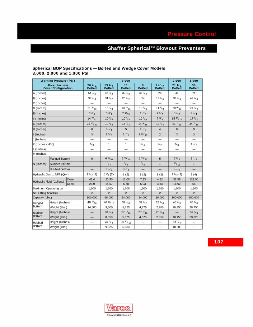
107
Pressure Control
Shaffer Spherical™ Blowout Preventers
Spherical BOP Specifications — Bolted and Wedge Cover Models 3,000, 2,000 and 1,000 PSI
Working Pressure (PSI) 3,000 2,000 1,000Bore (Inches)
Cover Configuration20 3/4 Bolted
13 5/8 Bolted
11Bolted
9Bolted
7 1/16 Bolted
21 1/4 Bolted
30Bolted
A (Inches) 54 1/8 46 3/8 39 7/8 35 1/2 29 49 71
B (Inches) 39 1/4 31 1/2 26 1/2 24 19 1/4 39 1/4 49 3/4C (Inches) — — — — — — —
D (Inches) 21 3/16 16 1/8 13 7/16 13 5/8 11 5/8 20 9/16 24 3/4
E (Inches) 3 3/4 3 3/4 2 1/16 1 7/8 2 5/8 3 1/8 4 1/4
F (Inches) 14 7/32 10 7/8 10 1/8 10 1/4 7 3/4 15 13/16 17 1/2
G (Inches) 21 13/32 19 5/8 14 3/4 14 9/16 13 3/4 21 1/16 34 7/16
H (Inches) 8 6 1/4 5 4 7/8 4 8 9
I (Inches) 3 2 5/8 1 7/8 1 15/16 2 3 3
J (Inches) — — — — — — —
K (Inches x 45°) 5/8 1 1 3/4 1/2 5/8 1 1/2L (Inches) — — — — — — —
M (Inches) — — — — — — —
N (Inches)
Flanged Bottom 9 6 7/16 5 15/16 5 13/16 5 7 3/8 9 1/2
Studded Bottom — 1/4 3/8 3/8 1 13/16 1
Hubbed Bottom — 3 1/2 3 3/4 — — 5 1/2 —
Hydraulic Conn.: NPT (Qty.) 1 1/2 (2) 11/2 (2) 1 (2) 1 (2) 1 (2) 1 1/2 (2) 2 (4)
Hydraulic Fluid (Gallons)Close 43.4 23.50 11.00 7.23 4.92 32.59 122.00
Open 26.9 14.67 6.78 5.03 3.43 16.92 55
Maximum Operating psi 1,500 1,500 1,500 1,500 1,500 1,500 1,500
No. Lifting Shackles 2 2 2 2 2 2 2
Capacity (Lbs.) 100,000 68,000 34,000 34,000 19,000 100,000 100,000
Flanged Bottom
Height (Inches) 48 7/16 40 11/16 32 7/8 32 1/2 29 1/8 46 1/8 65 5/8Weight (Lbs.) 14,600 9,500 5,825 4,775 2,900 10,850 28,750
Studded Bottom
Height (Inches) — 34 1/2 27 1/16 27 1/16 25 3/8 — 57 1/8Weight (Lbs.) — 8,850 5,675 4,675 2,850 10,150 28,025
Hubbed Bottom
Height (Inches) — 37 3/4 30 11/16 — — 44 1/4 —
Weight (Lbs.) — 9,325 5,683 — — 10,200 —
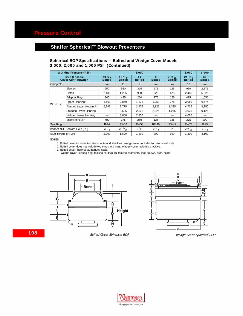
108
Pressure Control
Shaffer Spherical™ Blowout Preventers
Clamp No. — 11 9 — — 18 —
Wt. (Lbs.)
Element 950 550 325 275 125 950 2,875
Piston 2,485 1,225 950 625 425 2,485 5,025
Adapter Ring 840 425 250 275 125 475 1,050
Upper Housing1 3,660 2,850 1,575 1,350 775 3,050 6,575
Flanged Lower Housing2 6,745 3,775 2,475 2,125 1,325 4,725 9,850
Studded Lower Housing — 3,525 2,325 2,025 1,275 4,025 9,125
Hubbed Lower Housing — 3,600 2,350 — — 4,075 —
Miscellaneous3 400 275 250 125 125 275 900
Seal Ring R-74 RX-57 RX-53 RX-49 RX-45 RX-73 R-95
Bonnet Nut – Across Flats (In.) 3 1/8 2 15/16 2 3/4 2 3/8 2 2 9/16 3 1/2Stud Torque (Ft Lbs.) 2,200 1,800 1,500 900 500 1,200 3,100
NOTES:1. Bolted cover includes top studs, nuts and shackles. Wedge cover includes top studs and nuts.2. Bolted cover does not include top studs and nuts. Wedge cover includes shackles.3. Bolted cover: bonnet studs/nuts, seals.
Wedge cover: locking ring, locking studs/nuts, locking segments, jack screws, nuts, seals.
Spherical BOP Specifications — Bolted and Wedge Cover Models 3,000, 2,000 and 1,000 PSI (Continued)
Working Pressure (PSI) 3,000 2,000 1,000Bore (Inches)
Cover Configuration20 3/4 Bolted
13 5/8 Bolted
11Bolted
9Bolted
7 1/16 Bolted
21 1/4 Bolted
30Bolted
Bolted-Cover Spherical BOP
Wedge-Cover Spherical BOP
109
Pressure Control
Shaffer Spherical Bolted Cover BOPs
Shaffer Spherical Bolted Cover BOPs
Spherical BOP Parts — Bolted Cover Models
Item No.
Description Qty. Req.
No. Req.
Spare Parts
Working Pressure
(psi)10,000 5,000 5,000 5,000 5,000 3,000 3,000 3,000 3,000 3,000 2,000 1,000
Bore (Inches) 7 1/16 13 5/8 11 9 7 1/16 20 3/4 13 5/8 11 9 7 1/16 21 1/4 30
1 Lower Housing-Flanged 1 150982 152451 152406 152232 152173 156512 151974 152019 152178 152420 152204 155274
2 Upper Housing- Studded 1 150983 152453 152328 151002 151392 156513 150735 150486 150992 150717 150749 155272
3 Piston 1 150984 152148 152326 151003 150718 156523 156400 150498 152837 150718 155623 1559834 Adapter Ring 1 150985 151933 152323 152236 152163 156521 151964 152026 152827 151831 152183 155984
5 Sealing Element
Nitrile (Blue) 150987 150576 150810 150996 150847 150799 150576 150578 150996 150847 150799 155393Natural (Red) 150988 150577 150809 152272 150848 150800 150577 150579 152272 150848 150800 155392
6 Stud 1 Set1
NOTES:1. Part number shown is for one each. Quantity varies with size of spherical.
150989 150659 150648 150999 150730 156528 155661 150487 155663 150721 150832 155408
7 Nut 1 Set1 020111 020111 020110 020108 020106 020110 020109 020108 020106 020104 020107 020111
8 Seal-Piston I.D. Upper 1 1 031102 031097 031113 031110 031105 031108 031111 031099 031110 031105 031108 031225
9 Seal-Piston I.D. Lower 1 1 031102 030770 031152 031002 031000 030761 030780 031101 031002 031000 030761 031225
10 Seal-Piston O.D. 2 2 030765 031029 031018 030765 030780 031013 030782 030765 031012 030780 030767 031226
11 Seal-Adapter I.D.- Upper 1 1 031100 031096 031114 031109 031104 031107 031096 031098 031109 031104 031107 031224
12 Seal-Adapter I.D.-Lower 1 1 031100 030771 030781 031037 031002 031018 030771 030761 031037 031002 031018 031224
13 Seal-Adapter O.D. 1 1 030773 030772 030783 031126 030408 031031 031011 030760 030784 030408 031019 031020
14 Seal-Adapter Top 1 3 031035 031094 031115 031036 030405 031027 030773 031095 031145 030244 031027 031021
15 Wear Ring-Piston 2 150613 150613 150613 150613 150613 150613 150613 150613 150613 150613 150613 150613
16 Wear Rng-Lower Housing 1 150613 150613 150613 150613 150613 150613 150613 150613 150613 150613 150613 150613
17 Pipe Plug 2 066328 066329 066328 066328 066335 066329 066329 066335 066335 066335 066329 06633018 Anchor Shackle 2 060498 060498 060497 060494 060496 060498 060497 060499 060499 060500 060498 060498
19 Stud for Top API Flange 1 Set1 011020 011023 011026 011023 012262 011028 011016 011015 011014 011011 011023 011035
20 Nut for Top API Flange 1 Set1 020000 020012 020014 020012 020011 020015 020011 020011 020011 020003 020012 020015
NS2
2. NS Not shown.
Wear Ring-Adapter 1 150613 150613 152344 n/a 152344 152344 n/a n/a n/a 152344 152344 150613
NS2 Eye Bolts 2 050243 050243 050243 050243 050243 050243 050243 050243 050243 050243 050243 150912
NS2 Hammer Wrench 1 050713 050713 050825 050823 050821 050285 050824 050823 050821 050819 050822 050713
Size (Inches) 2 1/4 2 1/4 3 1/8 2 3/4 2 3/8 3 1/8 2 15/16 2 3/4 1 1/2 2 2 9/16 3 1/2
NS2 Pipe Plug 1/4” NPT
065008 065008 065008 065008 065008 065008 065008 065008 065008 065008 065008 065008
NS2 Seal Kit3
3. Not a standard accessory. Includes all recommended spare seals, Items 8 through 14.
1 155050 155070 155030 155076 155079 156527 155073 155075 155077 155078 155067 155412
NS2 Accumulator Kit4
4. Not a standard accessory.
1 152715 152717 152716 152716 152715 152717 152717 152715 152715 152715 152717 155970

110
Pressure Control
Shaffer Spherical Bolted Cover BOPs
Bolted Cover SBOP
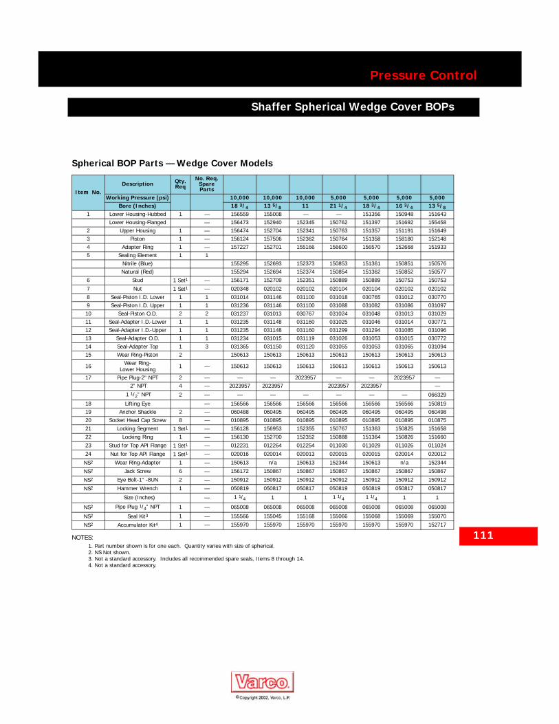
111
Pressure Control
Shaffer Spherical Wedge Cover BOPs
Shaffer Spherical Wedge Cover BOPs
Spherical BOP Parts — Wedge Cover Models
Item No.Description Qty.
ReqNo. Req.
Spare Parts
Working Pressure (psi) 10,000 10,000 10,000 5,000 5,000 5,000 5,000Bore (Inches) 18 3/4 13 5/8 11 21 1/4 18 3/4 16 3/4 13 5/8
1 Lower Housing-Hubbed 1 — 156559 155008 — — 151356 150948 151643 Lower Housing-Flanged — 156473 152940 152345 150762 151397 151692 1554582 Upper Housing 1 — 156474 152704 152341 150763 151357 151191 1516493 Piston 1 — 156124 157506 152362 150764 151358 158180 1521484 Adapter Ring 1 — 157227 152701 155166 156600 156570 152668 1519335 Sealing Element 1 1
Nitrile (Blue) 155295 152693 152373 150853 151361 150851 150576Natural (Red) 155294 152694 152374 150854 151362 150852 150577
6 Stud 1 Set1
NOTES:1. Part number shown is for one each. Quantity varies with size of spherical.
— 156171 152709 152351 150889 150889 150753 150753
7 Nut 1 Set1 — 020348 020102 020102 020104 020104 020102 0201028 Seal-Piston I.D. Lower 1 1 031014 031146 031100 031018 030765 031012 0307709 Seal-Piston I.D. Upper 1 1 031236 031146 031100 031088 031082 031086 03109710 Seal-Piston O.D. 2 2 031237 031013 030767 031024 031048 031013 03102911 Seal-Adapter I.D.-Lower 1 1 031235 031148 031160 031025 031046 031014 03077112 Seal-Adapter I.D.-Upper 1 1 031235 031148 031160 031299 031294 031085 03109613 Seal-Adapter O.D. 1 1 031234 031015 031119 031026 031053 031015 03077214 Seal-Adapter Top 1 3 031365 031150 031120 031055 031053 031065 03109415 Wear Ring-Piston 2 150613 150613 150613 150613 150613 150613 150613
16 Wear Ring-Lower Housing 1 — 150613 150613 150613 150613 150613 150613 150613
17 Pipe Plug-2” NPT 2 — — — 2023957 — — 2023957 — 2” NPT 4 — 2023957 2023957 2023957 2023957 —
1 1/2” NPT 2 — — — — — — — 066329
18 Lifting Eye — 156566 156566 156566 156566 156566 156566 15081919 Anchor Shackle 2 — 060488 060495 060495 060495 060495 060495 06049820 Socket Head Cap Screw 8 — 010895 010895 010895 010895 010895 010895 01087521 Locking Segment 1 Set1 — 156128 156953 152355 150767 151363 150825 15165822 Locking Ring 1 — 156130 152700 152352 150888 151364 150826 15166023 Stud for Top API Flange 1 Set1 — 012231 012264 012254 011030 011029 011026 011024
24 Nut for Top API Flange 1 Set1 — 020016 020014 020013 020015 020015 020014 020012
NS2
2. NS Not shown.
Wear Ring-Adapter 1 — 150613 n/a 150613 152344 150613 n/a 152344
NS2 Jack Screw 6 — 156172 150867 150867 150867 150867 150867 150867
NS2 Eye Bolt-1” -8UN 2 — 150912 150912 150912 150912 150912 150912 150912
NS2 Hammer Wrench 1 — 050819 050817 050817 050819 050819 050817 050817
Size (Inches) — 1 1/4 1 1 1 1/4 1 1/4 1 1
NS2 Pipe Plug 1/4” NPT 1 — 065008 065008 065008 065008 065008 065008 065008
NS2 Seal Kit3
3. Not a standard accessory. Includes all recommended spare seals, Items 8 through 14.
1 — 155566 155045 155168 155066 155068 155069 155070
NS2 Accumulator Kit4
4. Not a standard accessory.
1 — 155970 155970 155970 155970 155970 155970 152717
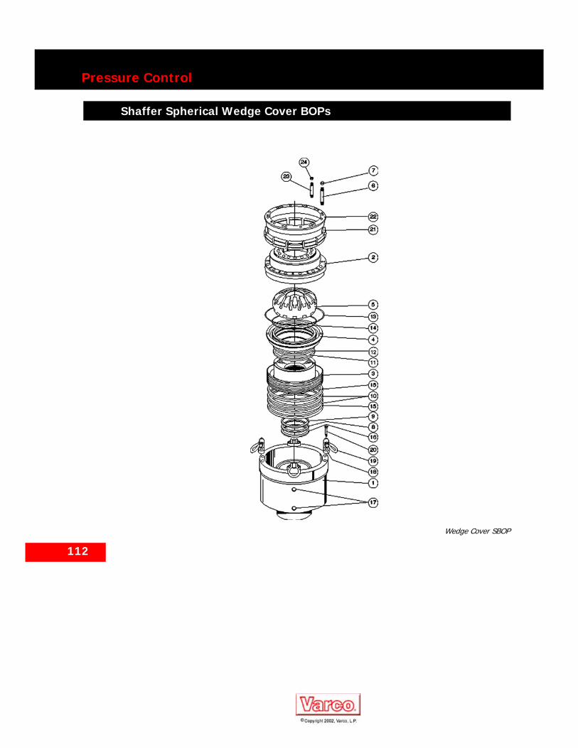
112
Pressure Control
Shaffer Spherical Wedge Cover BOPs
Shaffer Spherical Wedge Cover BOPs
Wedge Cover SBOP

113
Pressure Control
Shaffer Spherical Dual Wedge Cover BOPs
Shaffer Spherical Dual Wedge Cover BOPs
Spherical BOP Specifications – Wedge Cover Dual Models
Working Pressure (PSI) 5,000
Bore (Inches) Cover Configuration
21 1/4 18 3/4 16 3/4
Wedge Wedge1 Wedge
Dimensions (Inches)
A 71 66 1/4 60
B 66 7/8 62 1/4 56 1/4
C 69 1/2 64 5/8 56 3/4
D 80 1/4 75 1/4 67 3/8
E 15 3/8 12 1/4 7
F 9 8 7 1/2
G 5 1/2 7 4 3/4
H 22 5/16 18 7/8 16
I 3 5/16 2 5/8 2 3/4
J 18 5/8 17 1/2 15 1/2
K 22 3/16 18 7/8 16
L 26 13/16 23 1/8 22 1/16
M 22 3/16 20 3/4 15 3/4Hydraulic Connection: NPT (Qty.) 2 (8) 2 (8) 2 (4)
Hydraulic Fluid – Close (Gallons)2Open (Gallons)2
61.37 48.16 33.26
47.76 37.61 25.61
Recommended Operating Pressure (psi) 1,500 1,500 1,500
Number of Lifting ShacklesCapacity (Lbs.)
4 4 4
280,000 280,000 280,000
StuddedBottom
Height(Inches)
98 1/16 90 78 7/8
Weight(Lbs.) 88,300 68,300 47,100
Hubbed Bottom
Height(Inches)
103 11/163 963 84 9/163
Weight(Lbs.) 89,000 68,900 47,750
FlangedBottom
Height(Inches)
108 1/16 99 87 3/16
Weight(Lbs.) 90,200 69,600 48,000
Clamp Number(Hub Connection) 26 27 28
Element 1,4504 (lbs) 1,2504 (lbs) 8254 (lbs)
Piston 4,5004 (lbs) 3,4004 (lbs) 2,2504 (lbs)
Adapter Ring 2,3004 (lbs) 1,9004 (lbs) 1,0504 (lbs)
Upper Housing 8,800 (lbs) 6,500 (lbs) 4,375 (lbs)
Intermediate Housing 38,500 (lbs) 27,000 (lbs) 18,500 (lbs)
Studded Lower Housing 21,300 (lbs) 19,200 (lbs) 12,100 (lbs)
Hubbed Lower Housing 22,0003 (lbs) 20,000 (lbs) 12,750 (lbs)
Flanged Lower Housing 23,200 (lbs) 20,700 (lbs) 13,000 (lbs)
Miscellaneous 3,200 (lbs) 2,500 (lbs) 3,875 (lbs)
Seal Ring (Flanged/Studded Connections) BX-165 BX-163 BX-162
Locking Ring Nut – Across Flats (Inches) 2 2 1 5/8
Torque (Ft. Lbs.) 500 500 260
Housing Nut – Across Flats (Inches)
3 1/8 3 1/8 3 1/8
Torque (Ft Lbs.) 6,600 6,600 6,600
NOTES:1. 10,000 psi is available.2. Per element.3. 10,000 psi HUB.4. Each – two required.
Spherical BOP Specifications – Wedge Cover Dual Models (Continued)
Working Pressure (PSI) 5,000
Bore (Inches) Cover Configuration
21 1/4 18 3/4 16 3/4
Wedge Wedge1 Wedge
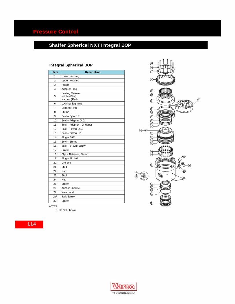
114
Pressure Control
Shaffer Spherical NXT Integral BOP
Shaffer Spherical NXT Integral BOP
Integral Spherical BOP
Item Description1 Lower Housing
2 Upper Housing
3 Piston
4 Adapter Ring
5Sealing ElementNitrile (Blue)Natural (Red)
6 Locking Segment
7 Locking Ring
8 Stump
9 Seal – Sym “U”
10 Seal – Adapter O.D.
11 Seal – Adapter I.D. Upper
12 Seal – Piston O.D.
13 Seal – Piston I.D.
14 Plug – SAE
15 Seal – Stump
16 Seal – 3” Cap Screw
17 Screw
18 Clip – Retainer, Stump
19 Plug – Skt Hd.
20 Life Eye
21 Stud
22 Nut
23 Stud
24 Nut
25 Screw
26 Anchor Shackle
27 Wearband
281
NOTES:1. NS Not Shown
Jack Screw
30 Screw
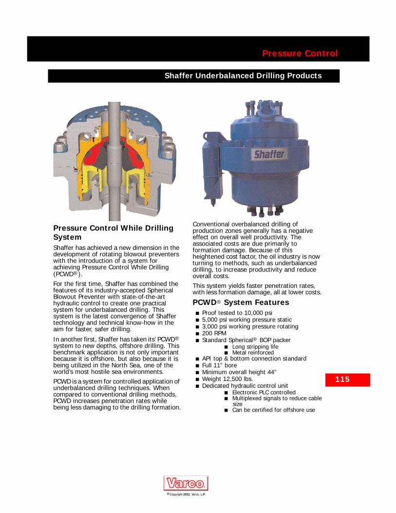
115
Pressure Control
Shaffer Underbalanced Drilling Products
Shaffer Underbalanced Drilling Products
Pressure Control While Drilling SystemShaffer has achieved a new dimension in the development of rotating blowout preventers with the introduction of a system for achieving Pressure Control While Drilling (PCWD®).For the first time, Shaffer has combined the features of its industry-accepted Spherical Blowout Preventer with state-of-the-art hydraulic control to create one practical system for underbalanced drilling. This system is the latest convergence of Shaffer technology and technical know-how in the aim for faster, safer drilling.
In another first, Shaffer has taken its’ PCWD® system to new depths, offshore drilling. This benchmark application is not only important because it is offshore, but also because it is being utilized in the North Sea, one of the world’s most hostile sea environments.PCWD is a system for controlled application of underbalanced drilling techniques. When compared to conventional drilling methods, PCWD increases penetration rates while being less damaging to the drilling formation.
Conventional overbalanced drilling of production zones generally has a negative effect on overall well productivity. The associated costs are due primarily to formation damage. Because of this heightened cost factor, the oil industry is now turning to methods, such as underbalanced drilling, to increase productivity and reduce overall costs.This system yields faster penetration rates, with less formation damage, all at lower costs.
PCWD® System Features■ Proof tested to 10,000 psi■ 5,000 psi working pressure static■ 3,000 psi working pressure rotating■ 200 RPM■ Standard Spherical® BOP packer
■ Long stripping life■ Metal reinforced
■ API top & bottom connection standard■ Full 11” bore■ Minimum overall height 44”■ Weight 12,500 lbs.■ Dedicated hydraulic control unit
■ Electronic PLC controlled■ Multiplexed signals to reduce cable
size■ Can be certified for offshore use
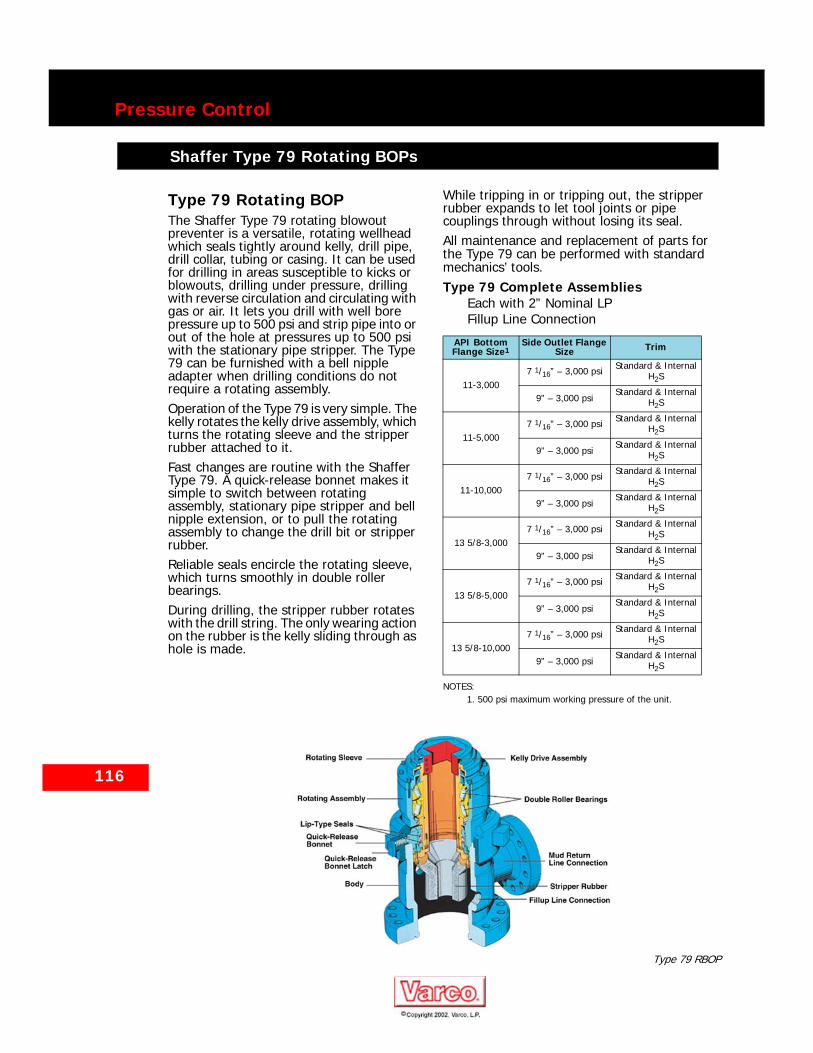
116
Pressure Control
Shaffer Type 79 Rotating BOPs
Shaffer Type 79 Rotating BOPs
Type 79 Rotating BOPThe Shaffer Type 79 rotating blowout preventer is a versatile, rotating wellhead which seals tightly around kelly, drill pipe, drill collar, tubing or casing. It can be used for drilling in areas susceptible to kicks or blowouts, drilling under pressure, drilling with reverse circulation and circulating with gas or air. It lets you drill with well bore pressure up to 500 psi and strip pipe into or out of the hole at pressures up to 500 psi with the stationary pipe stripper. The Type 79 can be furnished with a bell nipple adapter when drilling conditions do not require a rotating assembly.Operation of the Type 79 is very simple. The kelly rotates the kelly drive assembly, which turns the rotating sleeve and the stripper rubber attached to it.Fast changes are routine with the Shaffer Type 79. A quick-release bonnet makes it simple to switch between rotating assembly, stationary pipe stripper and bell nipple extension, or to pull the rotating assembly to change the drill bit or stripper rubber.Reliable seals encircle the rotating sleeve, which turns smoothly in double roller bearings.During drilling, the stripper rubber rotates with the drill string. The only wearing action on the rubber is the kelly sliding through as hole is made.
While tripping in or tripping out, the stripper rubber expands to let tool joints or pipe couplings through without losing its seal.All maintenance and replacement of parts for the Type 79 can be performed with standard mechanics’ tools.Type 79 Complete Assemblies
Each with 2” Nominal LP Fillup Line Connection
API Bottom Flange Size1
NOTES:1. 500 psi maximum working pressure of the unit.
Side Outlet Flange Size Trim
11-3,0007 1/16” – 3,000 psi Standard & Internal
H2S
9” – 3,000 psiStandard & Internal
H2S
11-5,0007 1/16” – 3,000 psi Standard & Internal
H2S
9” – 3,000 psiStandard & Internal
H2S
11-10,0007 1/16” – 3,000 psi Standard & Internal
H2S
9” – 3,000 psiStandard & Internal
H2S
13 5/8-3,0007 1/16” – 3,000 psi Standard & Internal
H2S
9” – 3,000 psiStandard & Internal
H2S
13 5/8-5,0007 1/16” – 3,000 psi Standard & Internal
H2S
9” – 3,000 psiStandard & Internal
H2S
13 5/8-10,0007 1/16” – 3,000 psi Standard & Internal
H2S
9” – 3,000 psiStandard & Internal
H2S
Type 79 RBOP

Pressure Control
Shaffer Gate Valves for Manual and Remote Operation
Shaffer Gate Valves for Manual and Remote Operation
Three basic models of Shaffer gate valves are offered — Type B, Type DB and Type HB.Shaffer Type B gate valves are designed specifically for choke and kill manifold service and use as isolation valves for outlets on BOP stacks. One-piece, slab-type gates seal fluids from either direction and are particularly suited to the demanding conditions of mud service. The seal is always effected against the downstream seat, and upstream pressure is in the body cavity at all times. This feature lowers handwheel torque requirements.
Type DB hydraulic valves are very reliable in choke and kill manifold applications which require remotely operated valves. The Type DB is produced by mounting a Type DB hydraulic operator on a Type B valve body that is equipped with a tail rod prep. This modification can be made without welding on the valve body.Type HB hydraulic valves are widely used in subsea BOP stack applications which require remotely operated choke and kill line valves adjacent to the blowout preventers.
117
Other sizes may be available upon request.
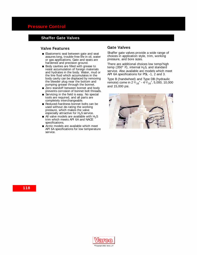
118
Pressure Control
Shaffer Gate Valves
Shaffer Gate Valves
Valve Features■ Elastomeric seal between gate and seat
assures long, trouble-free life in oil, water or gas applications. Gate and seats are hardened and precision ground.
■ Body cavities are filled with grease to resist accumulation of foreign materials and hydrates in the body. Water, mud or the line fluid which accumulates in the body cavity can be displaced by removing the bleeder plug near the bottom and pumping grease through the bonnet.
■ Zero standoff between bonnet and body prevents corrosion of bonnet bolt threads.
■ Servicing in the field is easy. No special tools are required, and all parts are completely interchangeable.
■ Reduced-hardness bonnet bolts can be used without de-rating the working pressure, which makes the valve especially attractive for H2S service.
■ All valve models are available with H2S trim which meets API 6A and NACE specifications.
■ Arctic models are available which meet API 6A specifications for low temperature service.
Gate ValvesShaffer gate valves provide a wide range of choices in application style, trim, working pressure, and bore sizes.There are additional choices low temp/high temp (350° F), internal H2S, and standard service. Also available are models which meet API 6A specifications for PSL -1, 2 and 3.Type B (handwheel) and Type DB (hydraulic remote) come in 2 1/16” - 4 1/16”, 5,000, 10,000 and 15,000 psi.
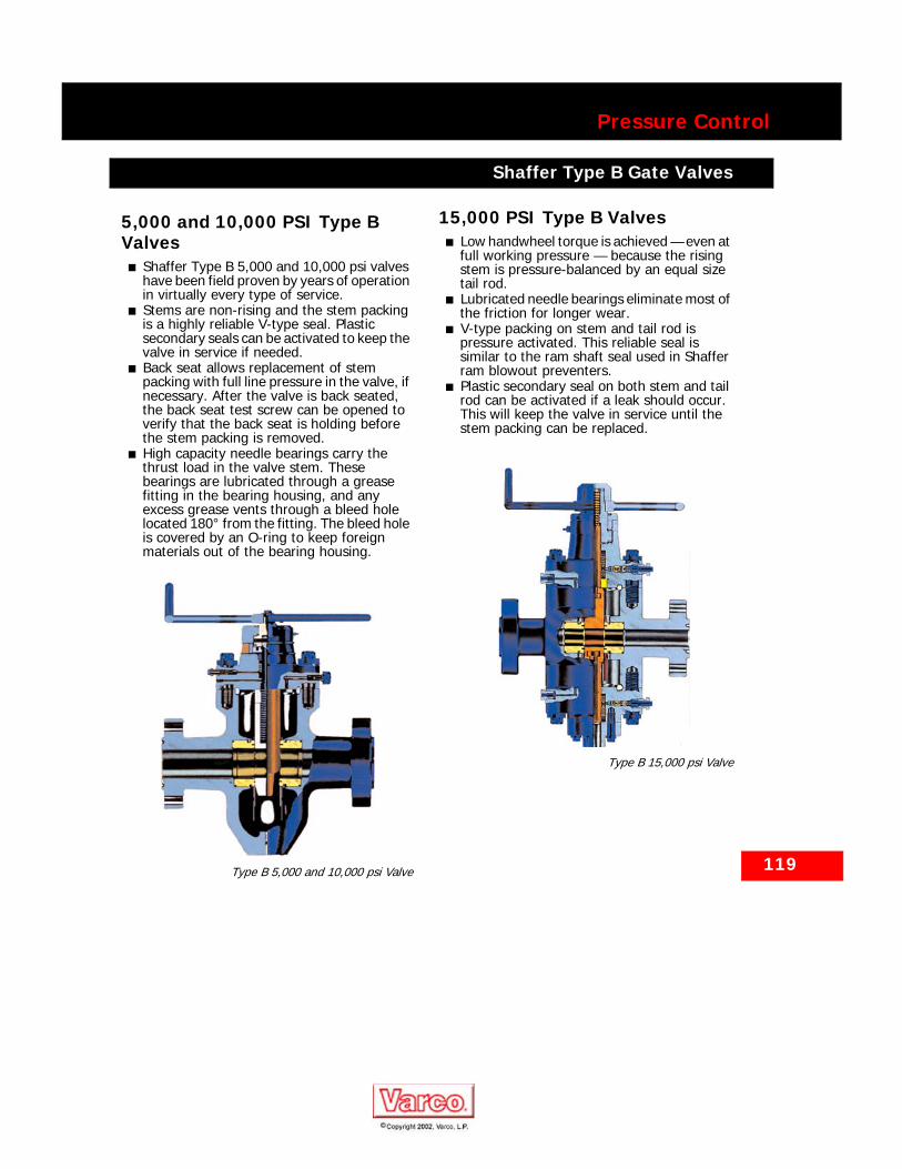
119
Pressure Control
Shaffer Type B Gate Valves
Shaffer Type B Gate Valves
5,000 and 10,000 PSI Type B Valves
■ Shaffer Type B 5,000 and 10,000 psi valves have been field proven by years of operation in virtually every type of service.
■ Stems are non-rising and the stem packing is a highly reliable V-type seal. Plastic secondary seals can be activated to keep the valve in service if needed.
■ Back seat allows replacement of stem packing with full line pressure in the valve, if necessary. After the valve is back seated, the back seat test screw can be opened to verify that the back seat is holding before the stem packing is removed.
■ High capacity needle bearings carry the thrust load in the valve stem. These bearings are lubricated through a grease fitting in the bearing housing, and any excess grease vents through a bleed hole located 180° from the fitting. The bleed hole is covered by an O-ring to keep foreign materials out of the bearing housing.
Type B 5,000 and 10,000 psi Valve
15,000 PSI Type B Valves■ Low handwheel torque is achieved — even at
full working pressure — because the rising stem is pressure-balanced by an equal size tail rod.
■ Lubricated needle bearings eliminate most of the friction for longer wear.
■ V-type packing on stem and tail rod is pressure activated. This reliable seal is similar to the ram shaft seal used in Shaffer ram blowout preventers.
■ Plastic secondary seal on both stem and tail rod can be activated if a leak should occur. This will keep the valve in service until the stem packing can be replaced.
Type B 15,000 psi Valve
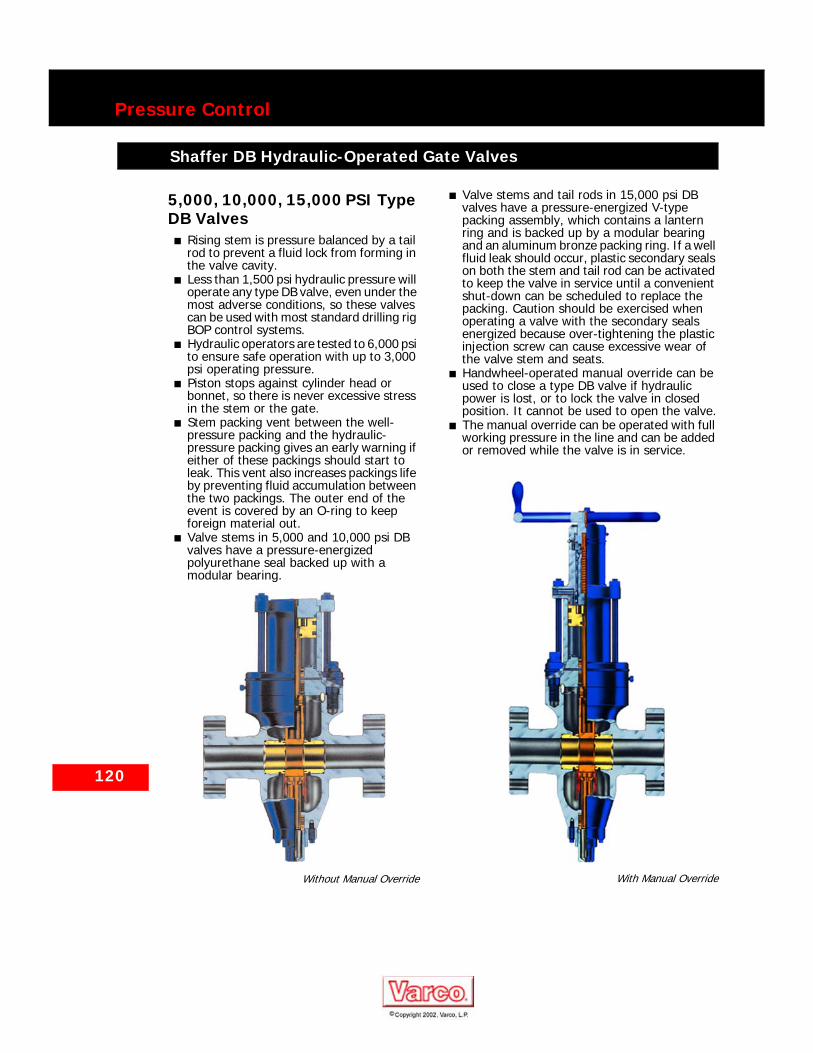
120
Pressure Control
Shaffer DB Hydraulic-Operated Gate Valves
Shaffer DB Hydraulic-Operated Gate Valves
5,000, 10,000, 15,000 PSI Type DB Valves
■ Rising stem is pressure balanced by a tail rod to prevent a fluid lock from forming in the valve cavity.
■ Less than 1,500 psi hydraulic pressure will operate any type DB valve, even under the most adverse conditions, so these valves can be used with most standard drilling rig BOP control systems.
■ Hydraulic operators are tested to 6,000 psi to ensure safe operation with up to 3,000 psi operating pressure.
■ Piston stops against cylinder head or bonnet, so there is never excessive stress in the stem or the gate.
■ Stem packing vent between the well-pressure packing and the hydraulic-pressure packing gives an early warning if either of these packings should start to leak. This vent also increases packings life by preventing fluid accumulation between the two packings. The outer end of the event is covered by an O-ring to keep foreign material out.
■ Valve stems in 5,000 and 10,000 psi DB valves have a pressure-energized polyurethane seal backed up with a modular bearing.
Without Manual Override
■ Valve stems and tail rods in 15,000 psi DB valves have a pressure-energized V-type packing assembly, which contains a lantern ring and is backed up by a modular bearing and an aluminum bronze packing ring. If a well fluid leak should occur, plastic secondary seals on both the stem and tail rod can be activated to keep the valve in service until a convenient shut-down can be scheduled to replace the packing. Caution should be exercised when operating a valve with the secondary seals energized because over-tightening the plastic injection screw can cause excessive wear of the valve stem and seats.
■ Handwheel-operated manual override can be used to close a type DB valve if hydraulic power is lost, or to lock the valve in closed position. It cannot be used to open the valve.
■ The manual override can be operated with full working pressure in the line and can be added or removed while the valve is in service.
With Manual Override

121
Pressure Control
Shaffer Type HB Hydraulic-Operated Gate Valves for Subsea Sys-
Shaffer Type HB Hydraulic-Operated Gate Valves for Subsea Systems
5,000 and 10,000 PSI Type HB Valves
■ One, or two, hydraulic lines can be used to operate a Type B valve, and it’s easy to convert from one arrangement to the other. Such conversions are sometimes necessary when a stack is modified and a greater or lesser number of control functions becomes available.
■ Pressure is sealed from either direction, and so the BOP stack can be tested separately from the choke and kill lines.
■ HB valves cannot be pressure locked. This is prevented by the pressure balancing tail rod and the use of a downstream seal.
■ Less than 1,500 psi hydraulic pressure will operate any Type HB valve, even under the most adverse conditions, and so any standard drilling rig hydraulic system can be used.
■ Cylinders are tested to 6,000 psi to assure safer operation up to 3,000 psi hydraulic pressure.
■ Thrust bearings between spring and piston allow the spring to rotate as it is compressed and extended. This reduces spring stress and increases spring life. It also removes the turning moment from the piston and stem assembly, increasing the life of those components.
■ Spring can be removed safely during maintenance operations because it is decompressed as the cylinder cap is unscrewed. After the spring is completely decompressed, several additional turns are required to remove the cylinder cap.
■ Cylinder cap is easy to remove because thrust bearings on top of the piston eliminate most of the friction as the cap is unscrewed. The Acme threads are plated for corrosion resistance.
■ There is never excessive stress in the stem or gate. This is because the piston stops against the cylinder cap or a positive stop on the stem.
■ Stem packing vent between the well-pressure packing and the hydraulic-pressure packing prevents hydraulic operating fluid from being contaminated by well fluid should the well-pressure packing fail. This vent also increases packing life by preventing fluid accumulation between the two packings. The outer end of the vent is covered by an O-ring to keep foreign material out.
The HB valve with short sea chest requires two hydraulic lines — one to pump and hold
the valve open and the other to close it. Should the hydraulic pressure fail for any reason, the spring closes the valve. No line fluid is displaced while the valve is opened because the pressure-balancing tail rod is the same diameter as the stem.Periodically, valves used in drilling mud service should be cycled several times with clear water in the line. This will help remove solids that can accumulate in the valve cavity.
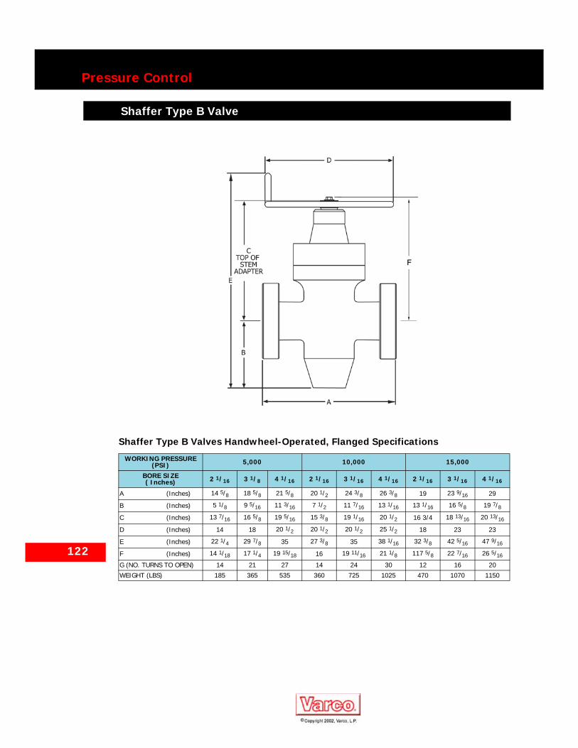
122
Pressure Control
Shaffer Type B Valve
Shaffer Type B Valve
Shaffer Type B Valves Handwheel-Operated, Flanged Specifications
WORKING PRESSURE (PSI) 5,000 10,000 15,000
BORE SIZE ( Inches) 2 1/16 3 1/8 4 1/16 2 1/16 3 1/16 4 1/16 2 1/16 3 1/16 4 1/16
A (Inches) 14 5/8 18 5/8 21 5/8 20 1/2 24 3/8 26 3/8 19 23 9/16 29
B (Inches) 5 1/8 9 5/16 11 3/16 7 1/2 11 7/16 13 1/16 13 1/16 16 5/8 19 7/8
C (Inches) 13 7/16 16 5/8 19 5/16 15 3/8 19 1/16 20 1/2 16 3/4 18 13/16 20 13/16
D (Inches) 14 18 20 1/2 20 1/2 20 1/2 25 1/2 18 23 23
E (Inches) 22 1/4 29 7/8 35 27 3/8 35 38 1/16 32 3/8 42 5/16 47 9/16
F (Inches) 14 1/18 17 1/4 19 15/18 16 19 11/16 21 1/8 117 5/8 22 7/16 26 5/16
G (NO. TURNS TO OPEN) 14 21 27 14 24 30 12 16 20
WEIGHT (LBS) 185 365 535 360 725 1025 470 1070 1150
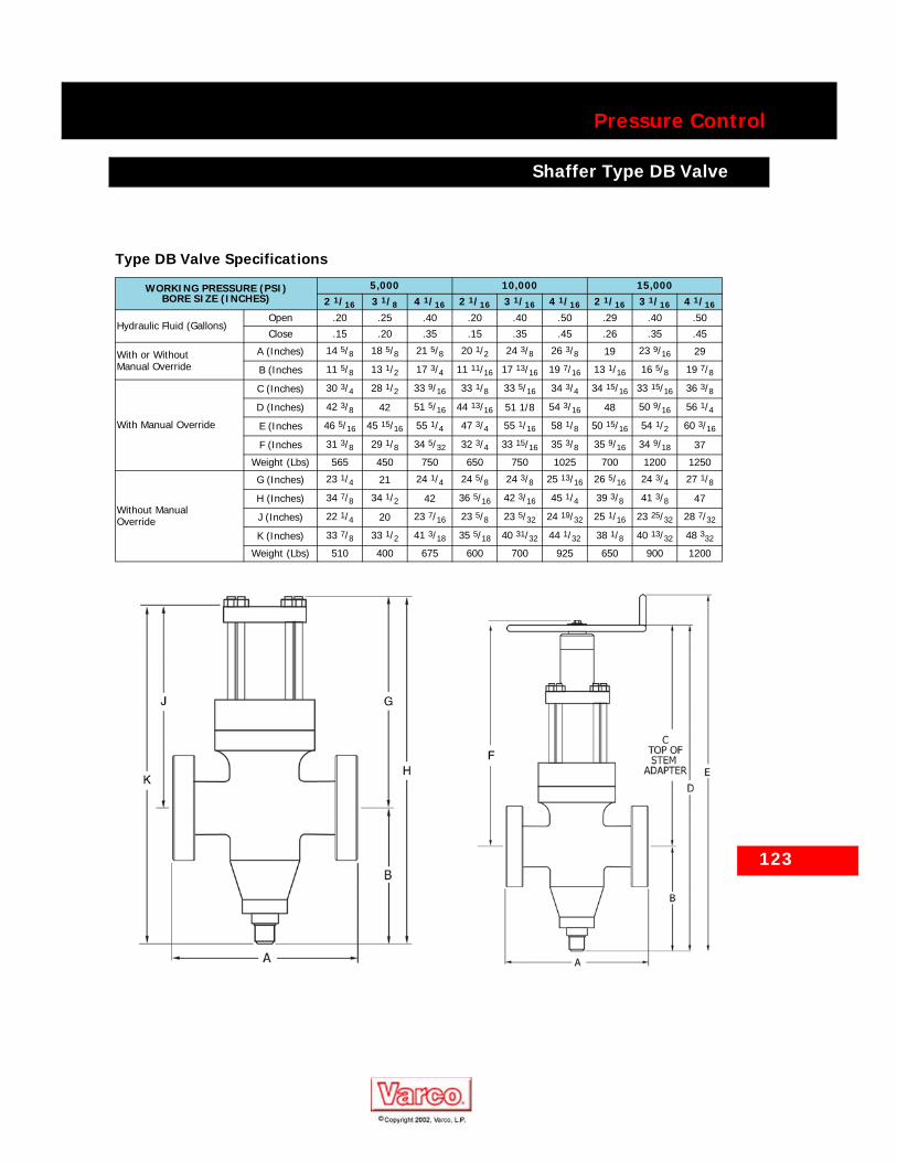
Pressure Control
Shaffer Type DB Valve
Shaffer Type DB Valve
Type DB Valve Specifications
WORKING PRESSURE (PSI)BORE SIZE (INCHES)
5,000 10,000 15,0002 1/16 3 1/8 4 1/16 2 1/16 3 1/16 4 1/16 2 1/16 3 1/16 4 1/16
Hydraulic Fluid (Gallons)Open .20 .25 .40 .20 .40 .50 .29 .40 .50
Close .15 .20 .35 .15 .35 .45 .26 .35 .45
With or Without Manual Override
A (Inches) 14 5/8 18 5/8 21 5/8 20 1/2 24 3/8 26 3/8 19 23 9/16 29
B (Inches 11 5/8 13 1/2 17 3/4 11 11/16 17 13/16 19 7/16 13 1/16 16 5/8 19 7/8
With Manual Override
C (Inches) 30 3/4 28 1/2 33 9/16 33 1/8 33 5/16 34 3/4 34 15/16 33 15/16 36 3/8
D (Inches) 42 3/8 42 51 5/16 44 13/16 51 1/8 54 3/16 48 50 9/16 56 1/4
E (Inches 46 5/16 45 15/16 55 1/4 47 3/4 55 1/16 58 1/8 50 15/16 54 1/2 60 3/16
F (Inches 31 3/8 29 1/8 34 5/32 32 3/4 33 15/16 35 3/8 35 9/16 34 9/18 37
Weight (Lbs) 565 450 750 650 750 1025 700 1200 1250
Without Manual Override
G (Inches) 23 1/4 21 24 1/4 24 5/8 24 3/8 25 13/16 26 5/16 24 3/4 27 1/8
H (Inches) 34 7/8 34 1/2 42 36 5/16 42 3/16 45 1/4 39 3/8 41 3/8 47
J (Inches) 22 1/4 20 23 7/16 23 5/8 23 5/32 24 19/32 25 1/16 23 25/32 28 7/32
K (Inches) 33 7/8 33 1/2 41 3/18 35 5/18 40 31/32 44 1/32 38 1/8 40 13/32 48 332
Weight (Lbs) 510 400 675 600 700 925 650 900 1200
123

124
Pressure Control
Shaffer Control Systems
Shaffer Control Systems
Koomey Control SystemsShaffer is able to offer unmatched experience and knowledge in BOP control systems as the only supplier of original Koomey products in the industry today. Koomey has a tradition of continuously leading the development of BOP controls, and Shaffer is carrying on the brand tradition with today’s new generation of BOP control systems.
Land UnitsShaffer manufactures BOP control units sized from the largest rigs to workover requirements. Utilizing the dependable Koomey design, these systems provide years of dependable use and service. Upgrades are also available. Air, electric and hydraulic panels can be supplied as replacements for original panels, or for auxiliary use.
Minute Man™ Control SystemsWhile the floating rig market uses the multiplexed electro-hydraulic or direct-hydraulic systems, high specification jack-ups are applying the lessons of the 4th Generation Mux systems for use in the Minute Man programmable logic control (PLC) unit for jack-ups and platforms as well as land and barge operations. These control systems offer the unique ability for control system automation while offering a
quick connection and disconnection of the control system to the control pod.
Hydraulic SystemsDirect hydraulic systems are available for use in water under 5,500-feet depth as well as land applications. A bias-pressure system improves response times of hydraulic systems in water depths in excess of 3,000 feet.A variety of test units, workover units, panels and other options are available utilizing direct hydraulic and PLC control units.
Deepwater Control SystemsShaffer introduced one of the first ultra-deep multiplex (MUX) control systems.This 4th generation deepwater system controls more than 100 functions on each pod, utilizing the efficient fiber optic cable system, eliminating the communication issues which would occur with a traditional control line communication at depths up to and exceeding 7,000 feet. All of the components used in the 4th generation MUX have been rated to operate in up to 10,000 feet water depths.The Shaffer design has lead the industry towards systems designed with maximum redundancy in mind as the time taken to run a control pod in deep water increases with depth.
Deep Water OptionsShaffer offers a deepwater system (up to 110 functions), and an 80-function system, that takes full advantage of our existing 80-line pod, while upgrading it to an electro-hydraulic system.
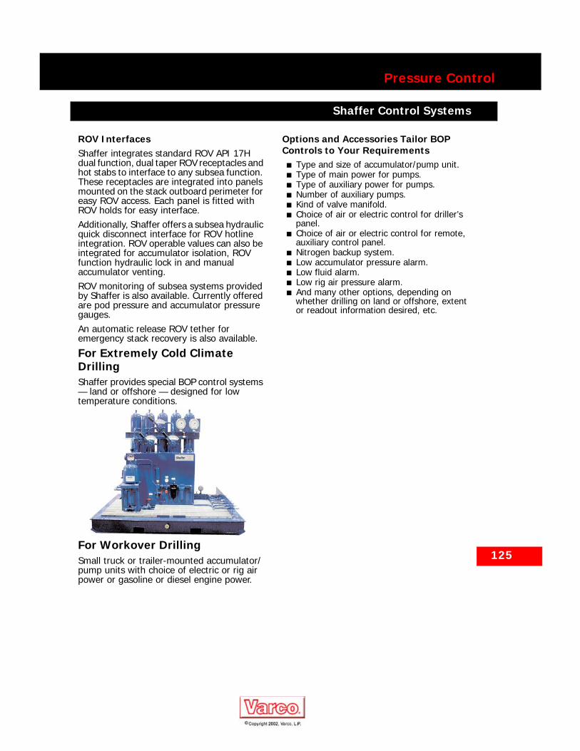
125
Pressure Control
Shaffer Control Systems
ROV InterfacesShaffer integrates standard ROV API 17H dual function, dual taper ROV receptacles and hot stabs to interface to any subsea function. These receptacles are integrated into panels mounted on the stack outboard perimeter for easy ROV access. Each panel is fitted with ROV holds for easy interface.Additionally, Shaffer offers a subsea hydraulic quick disconnect interface for ROV hotline integration. ROV operable values can also be integrated for accumulator isolation, ROV function hydraulic lock in and manual accumulator venting.ROV monitoring of subsea systems provided by Shaffer is also available. Currently offered are pod pressure and accumulator pressure gauges.An automatic release ROV tether for emergency stack recovery is also available.
For Extremely Cold Climate DrillingShaffer provides special BOP control systems — land or offshore — designed for low temperature conditions.
For Workover DrillingSmall truck or trailer-mounted accumulator/pump units with choice of electric or rig air power or gasoline or diesel engine power.
Options and Accessories Tailor BOPControls to Your Requirements
■ Type and size of accumulator/pump unit.■ Type of main power for pumps.■ Type of auxiliary power for pumps.■ Number of auxiliary pumps.■ Kind of valve manifold.■ Choice of air or electric control for driller’s
panel.■ Choice of air or electric control for remote,
auxiliary control panel.■ Nitrogen backup system.■ Low accumulator pressure alarm.■ Low fluid alarm.■ Low rig air pressure alarm.■ And many other options, depending on
whether drilling on land or offshore, extent or readout information desired, etc.
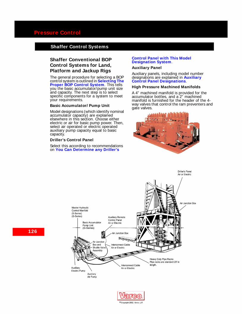
126
Pressure Control
Shaffer Control Systems
Shaffer Control Systems
Shaffer Conventional BOP Control Systems for Land, Platform and Jackup RigsThe general procedure for selecting a BOP control system is outlined in Selecting The Proper BOP Control System. This tells you the basic accumulator/pump unit size and capacity. The next step is to select specific components for a system to meet your requirements.Basic Accumulator/Pump UnitModel designations (which identify nominal accumulator capacity) are explained elsewhere in this section. Choose either electric or air for basic pump power. Then, select air operated or electric operated auxiliary pump capacity equal to basic capacity.Driller’s Control PanelSelect this according to recommendations on You Can Determine any Driller’s
Control Panel with This Model Designation System.Auxiliary PanelAuxiliary panels, including model number designations are explained in Auxiliary Control Panel Designations.High Pressure Machined ManifoldsA 4” machined manifold is provided for the accumulator bottles, and a 2” machined manifold is furnished for the header of the 4-way valves that control the ram preventers and gate valves.
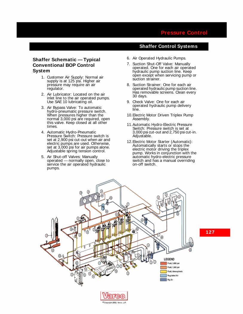
Pressure Control
Shaffer Control Systems
Shaffer Control Systems
Shaffer Schematic — Typical Conventional BOP Control System
1. Customer Air Supply: Normal air supply is at 125 psi. Higher air pressure may require an air regulator.
2. Air Lubricator: Located on the air inlet line to the air operated pumps. Use SAE 10 lubricating oil.
3. Air Bypass Valve: To automatic hydro-pneumatic pressure switch. When pressures higher than the normal 3,000 psi are required, open this valve. Keep closed at all other times.
4. Automatic Hydro-Pneumatic Pressure Switch: Pressure switch is set at 2,900 psi cut-out when air and electric pumps are used. Otherwise, set at 3,000 psi for air pumps alone. Adjustable spring tension control.
5. Air Shut-off Valves: Manually operated — normally open, close to service the air operated hydraulic pumps.
6. Air Operated Hydraulic Pumps.7. Suction Shut-Off Valve: Manually
operated. One for each air operated hydraulic pump suction line. Keep open except when servicing pump or suction strainer.
8. Suction Strainer: One for each air operated hydraulic pump suction line. Has removable screens. Clean every 30 days.
9. Check Valve: One for each air operated hydraulic pump delivery line.
10.Electric Motor Driven Triplex Pump Assembly.
11.Automatic Hydro-Electric Pressure Switch: Pressure switch is set at 3,000 psi cut-out and 2,750 psi cut-in. Adjustable.
12.Electric Motor Starter (Automatic): Automatically starts or stops the electric motor driving the triplex pump. Works in conjunction with the automatic hydro-electric pressure switch and has a manual overriding on-off switch.
127

128
Pressure Control
Shaffer Control Systems
13.Suction Shut-Off Valve: Manually operated, normally open. Located in the suction line of the electric pump.
14.Suction Strainer: Located in the suction line of the electric pump. Clean every 30 days.
15.Check Valve: Located in the delivery line of the triplex pump.
16.Electric Power: Customer’s connections.
17.Accumulators: Check nitrogen precharge in accumulator system every 30 days. Nitrogen precharge should be 1,000 psi +/- 10%. CAUTION: Use NITROGEN when adding to precharge. Other gases and air may cause fire and/or explosion.
18.Accumulator Relief Valve: Valve set to relieve at 3,300 psi.
19.Fluid Strainer: Located on the inlet side of the pressure reducing and regulating valves. Clean strainer every 30 days.
20.Pressure Reducing and Regulating Valve — Manually Operated: Adjust to the required continuous operating pressure of ram type BOPs.
21.Main Valve Header: 5,000 psi W.P., 2” machined.
22.4-Way Valves: With air cylinder operators for remote operation from the controls panels. Keep in standard operating mode (open or close), NEVER IN CENTER POSITION.
23.Bypass Valve: With air cylinder operator for remote operation from the controls panels. In “Low — 1,500” position, it puts regulated pressure on main valve header (21), and in “High — 3,000” position, it puts full accumulator pressure on the main valve header. Keep in “Low — 1,500” position unless 3,000 psi (or more) is required on ram type BOPs.
24.Accumulator Bank Isolator Valves: Manually operated, normally open.
25.Hydraulic Bleeder Valve: Manually operated — normally closed.
NOTE: This valve should be kept OPEN when precharging the accumulator bottles.
26.Panel-Unit Selector: Manual 3-way valve. Used to apply pilot air pressure to the air operated pressure reducing and regulating valve, either from the air regulator on the unit or from the air regulator on the remote control panel.
27.Pressure Reducing and Regulating Valve — Air Operated: Reduces the accumulator pressure to the required annular BOP operating pressure. Pressure can be varied for stripping operations. Maximum recommended operating pressure of the annular preventer should not be exceeded.
28.Accumulator Pressure Gauge.29.Manifold Pressure Gauge.30.Annular Preventer Pressure Gauge.31.Pneumatic Pressure Transmitter for
Accumulator Pressure.32.Pneumatic Pressure Transmitter for
Manifold Pressure.33.Pneumatic Pressure Transmitter for
Annular Pressure.34.Air Filter: Located on the supply line to
the air regulators.35.Air Regulator for Pressure Reducing
and Regulating Valve — Air Operated.36.Air Regulator for Pneumatic
Transmitter (33) for Annular Pressure.37.Air Regulator for Pneumatic Pressure
Transmitter (31) for Accumulator Pressure.
38.Air Regulator for Pneumatic Pressure Transmitter (32) for Manifold Pressure.
NOTE: Air regulator controls for pneumatic transmitters normally set at 15 psi. Increase or decrease air pressure to calibrate panel gauge to hydraulic pressure gauge on unit.
39.Air Junction Box: To connect the air lines on the unit to the air lines coming from the remote control panels through air cable.
40.Hydraulic Fluid Fill Port.41.Inspection Plug Port.42.Reservoir Drain Plug.
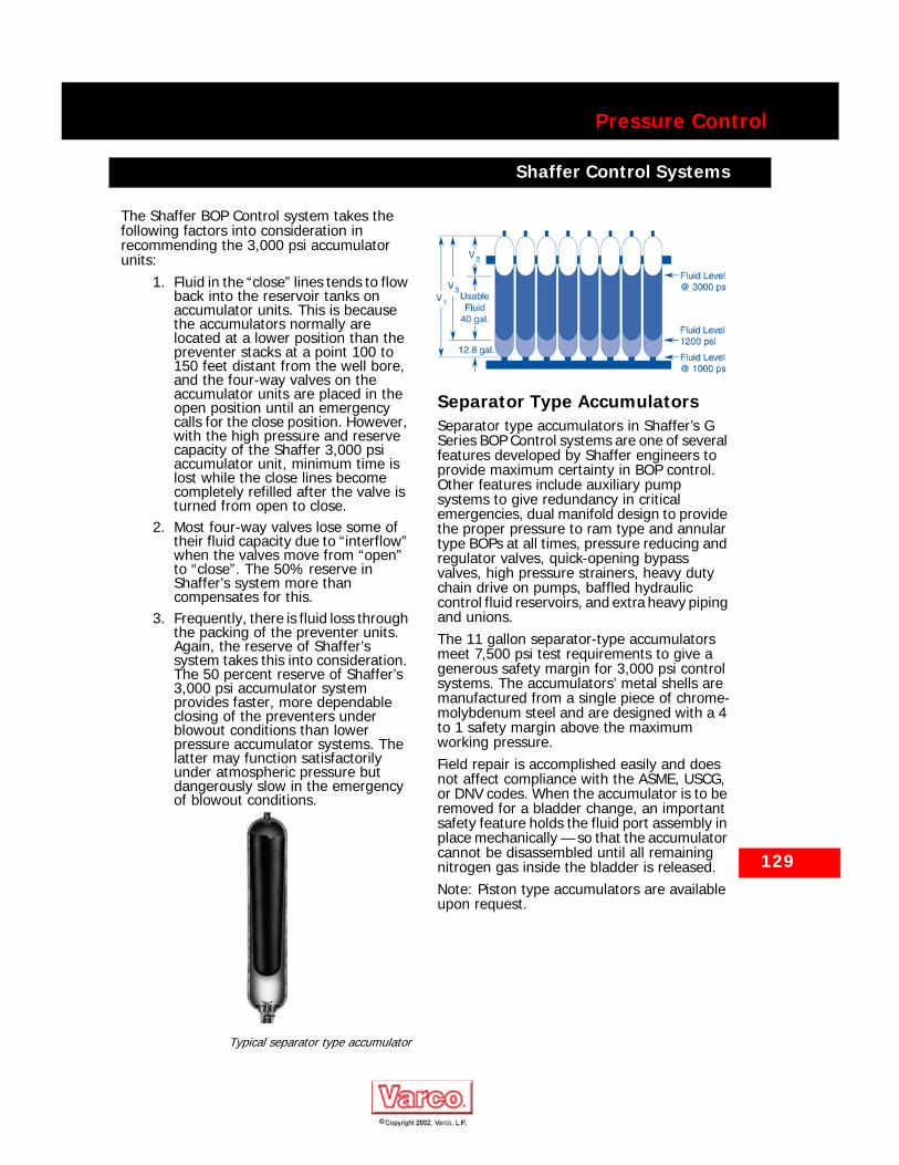
129
Pressure Control
Shaffer Control Systems
The Shaffer BOP Control system takes the following factors into consideration in recommending the 3,000 psi accumulator units:
1. Fluid in the “close” lines tends to flow back into the reservoir tanks on accumulator units. This is because the accumulators normally are located at a lower position than the preventer stacks at a point 100 to 150 feet distant from the well bore, and the four-way valves on the accumulator units are placed in the open position until an emergency calls for the close position. However, with the high pressure and reserve capacity of the Shaffer 3,000 psi accumulator unit, minimum time is lost while the close lines become completely refilled after the valve is turned from open to close.
2. Most four-way valves lose some of their fluid capacity due to “interflow” when the valves move from “open” to “close”. The 50% reserve in Shaffer’s system more than compensates for this.
3. Frequently, there is fluid loss through the packing of the preventer units. Again, the reserve of Shaffer’s system takes this into consideration. The 50 percent reserve of Shaffer’s 3,000 psi accumulator system provides faster, more dependable closing of the preventers under blowout conditions than lower pressure accumulator systems. The latter may function satisfactorily under atmospheric pressure but dangerously slow in the emergency of blowout conditions.
Typical separator type accumulator
Separator Type AccumulatorsSeparator type accumulators in Shaffer’s G Series BOP Control systems are one of several features developed by Shaffer engineers to provide maximum certainty in BOP control. Other features include auxiliary pump systems to give redundancy in critical emergencies, dual manifold design to provide the proper pressure to ram type and annular type BOPs at all times, pressure reducing and regulator valves, quick-opening bypass valves, high pressure strainers, heavy duty chain drive on pumps, baffled hydraulic control fluid reservoirs, and extra heavy piping and unions.The 11 gallon separator-type accumulators meet 7,500 psi test requirements to give a generous safety margin for 3,000 psi control systems. The accumulators’ metal shells are manufactured from a single piece of chrome-molybdenum steel and are designed with a 4 to 1 safety margin above the maximum working pressure.Field repair is accomplished easily and does not affect compliance with the ASME, USCG, or DNV codes. When the accumulator is to be removed for a bladder change, an important safety feature holds the fluid port assembly in place mechanically — so that the accumulator cannot be disassembled until all remaining nitrogen gas inside the bladder is released.Note: Piston type accumulators are available upon request.

130
Pressure Control
Shaffer Control Systems
Calculating Accumulator Size for Typical BOP Stack
Blowout Preventer Equipment Gallons To Close
Typical Annular BOPs (13 5/8" 5,000 psi W.P.) after normal wear 23.6
Three typical Ram BOPs (13 5/8" 10,000 psi W.P.) (3 x 11.6 gallons) 34.8
Total Gallons for Full Closure of All Preventers 58.4
Plus 50% Safety Factor 29.21
NOTES:1. Safety factor of 50% is recommended to provide for complete replenishment of fluid in “close” lines at time preventers are
activated. This safety factor also allows for loss of fluid capacity due to “interflow” in the four-way valves and possible lossthrough the packing of the preventer units.
Total Gallons Including Safety Factor 87.6
Calculation Of Accumulator SizeFor 3,000 PSI System
Therefore, by subtracting the remaining control fluid from the stored fluid:
6.6-1.6 = 5.0 Gallons of Usable Fluid
By noting that the 5 gallons of fluid is 1/2 the total Volume, a simple method for calculations can be used.Simple MethodThe minimum allowable pressure is considered to be 1,200 psi. The recommended pre-charge for 3,000 psi accumulators is 1,000 psi. Thus, the nominal (fluid and nitrogen volume) accumulator size may be calculated simply from the following factors:3000 PSI System: Gallons to close + safety factor x 2.0. Using the same BOP stack as above, the results are as follows:87.6 gallons x 2.0 = 175.2 gallons. Rounding off to the next higher increment of 10 gallons it is evident that 180 gallons (total fluid and nitrogen volume) are required.
131
Pressure Control
Shaffer Control Systems
Shaffer Control Systems
Selecting The Proper BOPControl System
1. Determine the size, working pressure, type and quantity of preventers and gate valves to be operated.
2. Refer to the Accumulator Size Recommendations for the accumulator size that will effectively operate the BOP stack.
3. Determine the pump capacity recommended for the system. To do this, obtain the total number of gallons required to close all preventers on an open hole, plus, open one hydraulically operated gate valve. Then, divide the total number of gallons by 3.0 minutes, and this will give the gallons per minute output required of the pump system.
4. The basic accumulator size and pump capacity are now known. Decide upon the basic type of control system preferred and select the components necessary for a system that meets all requirements.
Recommended Specifications: ControlSystems For Surface-Installed BOPsThe following general specifications meet most drilling requirements, but they are to serve as guidelines only. It is the responsibility of the equipment user to meet specific requirements of each drilling job.Accumulator/Pump Units — GeneralResponse Time. The control system should be capable of closing each ram type preventer within 6 seconds for preventer sizes up to 13-5/8” 10,000 psi, and capable of closing annular-type preventers within 19 seconds for sizes up to 13-5/8” 5,000 psi. For preventers requiring larger volumes, 1 1/2” valving on the control manifold should be specified.Volumetric Capacity. All BOP control systems should incorporate an accumulator unit with a volume adequate to close all preventers (with pumps inoperative), while retaining a pressure of 200 psi minimum above the precharge pressure but not less than 1,200 psi.Accumulator Manifolding. Accumulator manifolds or headers should be constructed with a minimum number of restrictions such
as small fittings and shut-off valves. Large internal diameter, machined manifolds are preferable because of minimum restrictions to flow and few potential leak paths — which are characteristic of screwed or welded types. Shut-off valves between the accumulators and 4-way control valves should be avoided. Each accumulator bottle should not have its own shut-off valve. Bottles should be repaired only during times when the rig activities do not require the control system and blowout preventers to be in service. The entire accumulator system should be bled down to zero pressure prior to working on the the accumulator bottles.Pumps and Power SystemsPump Capacity Pump capacity should be able to close all preventers on an open hole — plus opening one hydraulically operated gate valve — within 3.0 minutes or less, with the accumulator bottles removed from service, and attain a minimum pressure of 1,200 psi.Pump Sizing GPM output requirements are calculated and proper combination of pumps selected to meet current API standards.Dual Air/Electric Pumps A separate source of power should be available to operate the pump system, such as a combination of air operated and electrically operated pumps, with each pump source supplying approximately equal GPM output. If the primary pumps are electric, utilizing regular rig electric power, and if auxiliary pumps are operated, the rig air system for the auxiliary pumps should be independent of regular rig air and electric power. Conversely, if the basic pumps are air operated, utilizing regular rig air, and if the auxiliary pumps are electric, the electric pumps should have the proper size independent generator available continuously. For standard 3,000 psi systems, all pumps should activate automatically when system pressure drops to approximately 2,700 psi.Other Power Combinations A system with only multiple air operated pumps should have two separate air supplies so that at least half of the total GPM capacity continues to operate if the rig’s primary power systems are off. Similarly, a system with only multiple electric pumps should have two separate sources of electric power to ensure continued operation of at least half of the GPM

132
Pressure Control
Shaffer Control Systems
capacity if the rig’s primary power systems are off. Nitrogen backup systems may be supplied as a secondary power source for closing BOPs. They are also inexpensive insurance as a third source of power for emergency use.Control ValvesClearly marked nameplates should tell which preventer or hydraulic valve each 4-way valve operates and give the valve position (OPEN and CLOSE only). During drilling operations, valves should be left in either the OPEN or CLOSE position — never in the center position.GaugesLarge-face, easy-to-read gauges on BOP control panels should indicate the accumulator system operating pressure (accumulator pressure), the pressure downstream of the ram preventer regulator (manifold pressure), and the pressure downstream of the annular preventer regulator (annular pressure).FittingsAll manifolding should have a minimum number of flow restrictions, i.e., elbows, crosses, tee, manual gate valves. Manual gate valves, which do not clearly indicate open and closed position, easily could be left in a closed position when they should be left open.
Operating Fluid and ReservoirA clean, lightweight, high quality hydraulic control fluid, which is capable of being mixed with potable water, should be used as the operating fluid. Do not use motor oil, kerosene, diesel fuel, chain oil or petroleum products containing aromatics which can damage rubber components and seals.Reservoir capacity should equal approximately twice the usable fluid capacity of the accumulator system. Access ports of at least 4” I.D. at each end of the reservoir for visual inspection of the inside of the reservoir and to allow detection of any leaking components on the manifold. Internal baffles in the reservoir should restrict fluid movement when the unit is transported.
Driller’s Controls — GeneralDriller’s control panels on the rig floor near the driller should have a power source independent of the accumulator/pump unit. Complete destruction of the driller’s
panel, interconnecting cable or hose must not interfere with accumulator/pump operation. Hydraulically operated panels which receive their hydraulic operating fluid from the main accumulator system are not acceptable unless designed so that the destruction of the panel or the interconnecting hoses will not cause the accumulator system to be drained. Air operated panels, electrically operated panels and self-contained hydraulic panels (having their own hydraulic pump, accumulator and reservoir) are acceptable.A graphic display of the BOP stack on each control panel indicates clearly the position and operation of each BOP function and the position of each control valve. Gauges indicate accumulator pressure, manifold pressure and annular BOP pressure.All driller’s control panels — whether air, electric or hydraulic operated — have a sufficient number of valves to remotely operate all 4-way valves on the master hydraulic control manifold to either the OPEN or CLOSE position.
Air Operated Control PanelsIn addition to the general specifications mentioned above, air operated remote control panels should have a valve allowing remote operation of the regulator bypass valve on the ram preventers’ hydraulic manifold. A master air valve is required and must be activated before air flows to the other valves. Remote regulation of the annular pressure regulator should be incorporated into the panel. Air communication between the remote control panel and the hydraulic control manifold should be via multi-tube, bundled, flame-resistant hoses of minimum 3/8” O.D.
Electric Operated Control PanelsElectric operated remote control panels have indicating lights to show the status of the last command sent to each of the preventer functions. Control of the regulator bypass valve for the ram preventers (located on the hydraulic control manifold) are incorporated into the panel. A master panel pushbutton is recommended to activate all function switches. This requires a two-handed operation — guarding against accidental operation of BOPs by someone unintentionally bumping a pushbutton. Remote control of hydraulic pressure to the annular preventer should be included in the panel. All components must be explosion-proof — either by enclosure or by a nitrogen purge system.

133
Pressure Control
Shaffer Control Systems
Hydraulic Operated Control PanelsBesides meeting the applicable general specifications, hydraulic operated driller’s panels require a master hydraulic valve which must be activated before hydraulic pressure flows to the function valves. Remote regulation of the annular pressure regulator should be incorporated into the panel.Surface Control Electric Remote Control InterfaceAdvantages of PLC based, fiber-optic remote control communications vs. direct multi-conductor electric remote cable.
■ Safer, noise-free operation■ Accidental damage to fiber-optic
interconnecting cable does not cause any BOP control functions to operate.
■ Only remote communications will be lost, providing a safer method of remote control.
■ Outside electrical interference is eliminated for a “noise-free” communications signal.
Easier Cable Installation■ Fiber-optic cable is lighter and smaller in
diameter than the standard 60 to 90 multi-conductor electric cable previously used, allowing a shorter installation phase.
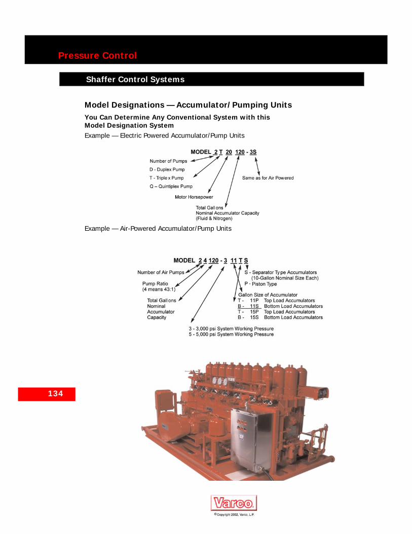
134
Pressure Control
Shaffer Control Systems
Shaffer Control Systems
Model Designations — Accumulator/Pumping UnitsYou Can Determine Any Conventional System with this Model Designation SystemExample — Electric Powered Accumulator/Pump Units
Example — Air-Powered Accumulator/Pump Units

Pressure Control
Shaffer Control Systems
Electric Powered Pump Assemblies for 3,000 PSI SystemsUnit Mounted. These pump assemblies can be mounted on the basic air operated accumulator unit to provide a dual source of power and to reduce pump-up time.Separate Skid Mount Available. For accumulator units already out in the field, this pump assembly can be skidded, sent to location and readily connected to any accumulator system to provide more fluid power.
Heavy Duty Chain and Sprocked Drive. This drive system has a life expectancy of more than 20 years. There are no belts to tighten or slip when the pump is needed.Reciprocating Plunger Pump. Unlike rotary piston vane type pumps, this heavy duty pump will stay in service when dust or small contaminants accidentally get into the accumulator system.Explosion-Proof Design. The electric motor, starter and pressure switch are completely explosion-proof.
135
Model Number Designation for Electric-Driven Pump Assemblies
DGE25 Duplex Pump Gasoline Engine Driven - Contact Shaffer.SDGE25 Duplex Pump Gasoline Engine Driven – Contact Shaffer.
Model Number Designation for Electric Driven Pump Assemblies
ModelNumber
Overall GPM At 3,000 PSI
(211 kg/cm2)
Approximate Overall Dimensions and Weight
Width Depth Height Dry Weight
Gallons Liters Inches mm Inches mm Inches mm Lbs. kgUnit-Mounted Pump Assemblies
D25-3-3 1.14 4.32 39 991 20 508 32 813 612 278D25-5-3 2.19 8.29 39 991 20 508 32 813 612 278D25-7 1/2-3 2.50 9.46 39 991 24 610 34 864 657 298T315-10-3 4.55 17.22 57 1448 27 686 34 864 882 400T315-15-3 6.40 24.23 57 1448 27 686 35 889 952 432T315-20-3 8.70 32.93 57 1448 27 686 36 914 1002 455T315-25-3 11.40 43.15 57 1448 29 727 39 991 1130 513T330-30-3 14.20 53.75 68 1727 44 1118 44 1118 1395 633T360-40-3 20.20 76.47 68 1727 44 1118 45 1142 1810 821T360-50-3 25.20 95.39 68 1727 44 1118 45 1142 1895 860T360-60-3 30.00 113.56 70 1778 45 1143 47 1194 2230 1012
Skid-Mounted Pump AssembliesSD25-3-3 1.14 4.32 39 991 20 508 40 1016 650 295SD25-5-3 2.19 8.29 39 991 20 508 40 1016 650 295SD25-7 1/2-3 2.50 9.46 39 991 24 610 40 1016 700 318ST315-10-3 4.55 17.22 57 1448 27 686 48 1219 930 422ST315-15-3 6.40 24.23 57 1448 27 686 48 1219 1000 454ST315-20-3 8.70 32.93 57 1448 27 686 48 1219 1150 522ST315-25-3 11.40 43.15 57 1448 27 686 48 1219 1180 535ST330-30-3 14.20 53.75 68 1727 46 1168 50 1270 1450 658ST360-40-3 20.20 76.47 68 1727 46 1168 50 1270 1865 846ST360-50-3 25.20 95.39 68 1727 46 1168 50 1270 1950 885ST360-60-3 30.00 113.56 70 1778 48 1219 54 1372 2290 1039
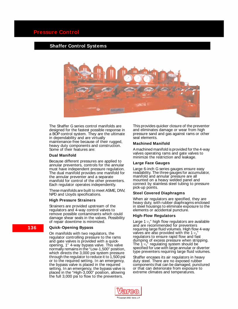
136
Pressure Control
Shaffer Control Systems
The Shaffer G series control manifolds are designed for the fastest possible response in a BOP control system. They are the ultimate in dependability and are virtually maintenance-free because of their rugged, heavy duty components and construction. Some of their features are:Dual ManifoldBecause different pressures are applied to annular preventers, controls for the annular must have independent pressure regulation. The dual manifold provides one manifold for the annular preventer and a separate manifold for control of the other preventers. Each regulator operates independently.These manifolds are built to meet ASME, DNV, NPD and Lloyds specifications.High Pressure StrainersStrainers are provided upstream of the regulators and 4-way control valves to remove possible contaminants which could damage shear seals in the valves. Possibility of repair downtime is minimized. Quick-Opening BypassOn manifolds with two regulators, the regulator controlling pressure to the rams and gate valves is provided with a quick-opening, 1” 4-way bypass valve. This valve normally remains in the “Low-1,500” position, which directs the 3,000 psi system pressure through the regulator to reduce it to 1,500 psi or to the required setting. In an emergency, the bypass valve is placed in the required setting. In an emergency, the bypass valve is placed in the “High-3,000” position, allowing the full 3,000 psi to flow to the preventers.
This provides quicker closure of the preventer and eliminates damage or wear from high pressure sand and gas against rams or other seal elements.Machined ManifoldA machined manifold is provided for the 4-way valves operating rams and gate valves to minimize the restriction and leakage.Large Face GaugesLarge 6-inch G series gauges ensure easy readability. The three gauges for accumulator, manifold and annular pressure are all mounted on a heavy welded panel and connect by stainless steel tubing to pressure pick-up points.Steel Covered DiaphragmsWhen air regulators are specified, they are heavy duty, with rubber diaphragms enclosed in steel housings to eliminate exposure to the elements or accidental puncture.High-Flow RegulatorsLarge 1 1/2” high flow regulators are available and are recommended for preventers requiring large fluid volumes. High flow 4-way valves are also provided with the 1 1/2” regulators to ensure rapid flow and fast dumping of excess pressure when stripping. The 1 1/2” regulating system should be specified for use with large annular or diverter type preventers requiring large fluid volumes.Shaffer encases its air regulators in heavy duty steel. There are no exposed rubber components that can be damaged, punctured or that can deteriorate from exposure to extreme climates and temperatures.
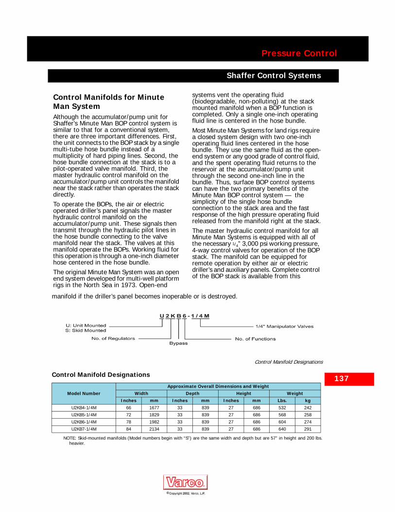
Pressure Control
Shaffer Control Systems
Shaffer Control Systems
Control Manifolds for Minute Man SystemAlthough the accumulator/pump unit for Shaffer’s Minute Man BOP control system is similar to that for a conventional system, there are three important differences. First, the unit connects to the BOP stack by a single multi-tube hose bundle instead of a multiplicity of hard piping lines. Second, the hose bundle connection at the stack is to a pilot-operated valve manifold. Third, the master hydraulic control manifold on the accumulator/pump unit controls the manifold near the stack rather than operates the stack directly.To operate the BOPs, the air or electric operated driller’s panel signals the master hydraulic control manifold on the accumulator/pump unit. These signals then transmit through the hydraulic pilot lines in the hose bundle connecting to the valve manifold near the stack. The valves at this manifold operate the BOPs. Working fluid for this operation is through a one-inch diameter hose centered in the hose bundle.The original Minute Man System was an open end system developed for multi-well platform rigs in the North Sea in 1973. Open-end
systems vent the operating fluid (biodegradable, non-polluting) at the stack mounted manifold when a BOP function is completed. Only a single one-inch operating fluid line is centered in the hose bundle.Most Minute Man Systems for land rigs require a closed system design with two one-inch operating fluid lines centered in the hose bundle. They use the same fluid as the open-end system or any good grade of control fluid, and the spent operating fluid returns to the reservoir at the accumulator/pump unit through the second one-inch line in the bundle. Thus, surface BOP control systems can have the two primary benefits of the Minute Man BOP control system — the simplicity of the single hose bundle connection to the stack area and the fast response of the high pressure operating fluid released from the manifold right at the stack.The master hydraulic control manifold for all Minute Man Systems is equipped with all of the necessary 1/4” 3,000 psi working pressure, 4-way control valves for operation of the BOP stack. The manifold can be equipped for remote operation by either air or electric driller’s and auxiliary panels. Complete control of the BOP stack is available from this
137
manifold if the driller’s panel becomes inoperable or is destroyed.
Control Manifold Designations
NOTE: Skid-mounted manifolds (Model numbers begin with “S”) are the same width and depth but are 57” in height and 200 lbs.heavier.
Control Manifold Designations
Model NumberApproximate Overall Dimensions and Weight
Width Depth Height WeightInches mm Inches mm Inches mm Lbs. kg
U2KB4-1/4M 66 1677 33 839 27 686 532 242
U2KB5-1/4M 72 1829 33 839 27 686 568 258
U2KB6-1/4M 78 1982 33 839 27 686 604 274
U2KB7-1/4M 84 2134 33 839 27 686 640 291
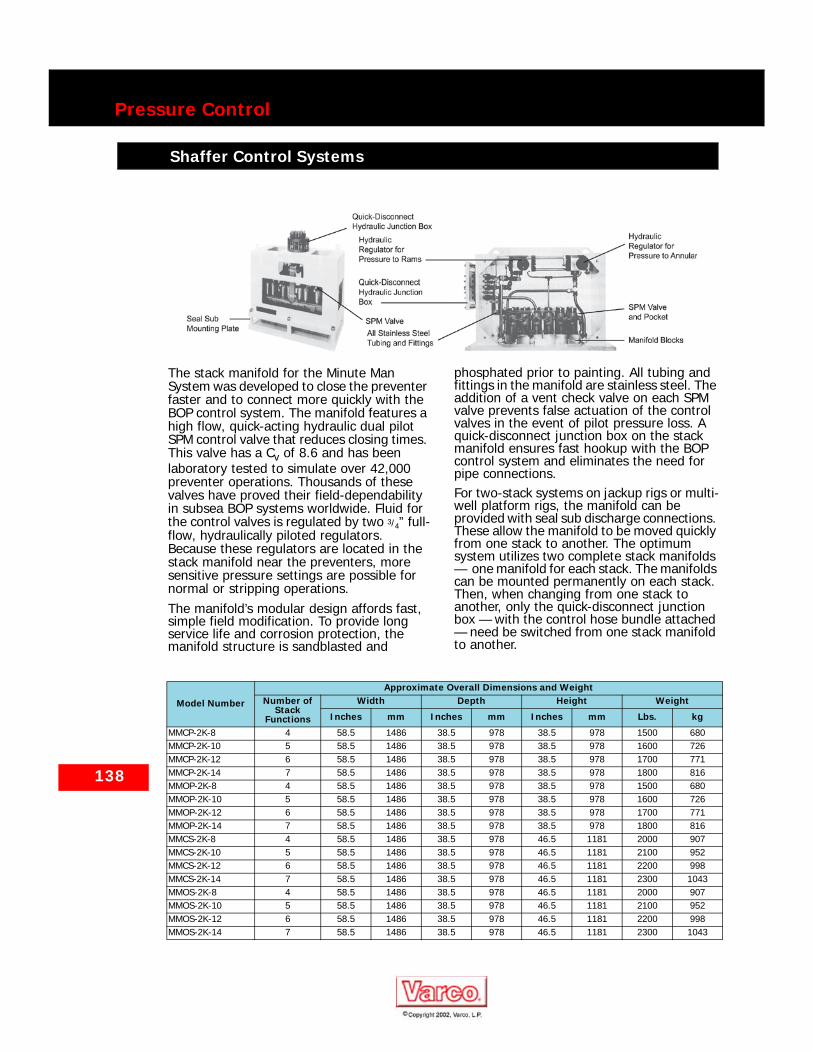
138
Pressure Control
Shaffer Control Systems
The stack manifold for the Minute Man System was developed to close the preventer faster and to connect more quickly with the BOP control system. The manifold features a high flow, quick-acting hydraulic dual pilot SPM control valve that reduces closing times. This valve has a Cv of 8.6 and has been laboratory tested to simulate over 42,000 preventer operations. Thousands of these valves have proved their field-dependability in subsea BOP systems worldwide. Fluid for the control valves is regulated by two 3/4” full-flow, hydraulically piloted regulators. Because these regulators are located in the stack manifold near the preventers, more sensitive pressure settings are possible for normal or stripping operations.The manifold’s modular design affords fast, simple field modification. To provide long service life and corrosion protection, the manifold structure is sandblasted and
phosphated prior to painting. All tubing and fittings in the manifold are stainless steel. The addition of a vent check valve on each SPM valve prevents false actuation of the control valves in the event of pilot pressure loss. A quick-disconnect junction box on the stack manifold ensures fast hookup with the BOP control system and eliminates the need for pipe connections.For two-stack systems on jackup rigs or multi-well platform rigs, the manifold can be provided with seal sub discharge connections. These allow the manifold to be moved quickly from one stack to another. The optimum system utilizes two complete stack manifolds — one manifold for each stack. The manifolds can be mounted permanently on each stack. Then, when changing from one stack to another, only the quick-disconnect junction box — with the control hose bundle attached — need be switched from one stack manifold to another.
Shaffer Control Systems
Model Number
Approximate Overall Dimensions and WeightNumber of
Stack Functions
Width Depth Height Weight
Inches mm Inches mm Inches mm Lbs. kg
MMCP-2K-8 4 58.5 1486 38.5 978 38.5 978 1500 680MMCP-2K-10 5 58.5 1486 38.5 978 38.5 978 1600 726MMCP-2K-12 6 58.5 1486 38.5 978 38.5 978 1700 771MMCP-2K-14 7 58.5 1486 38.5 978 38.5 978 1800 816MMOP-2K-8 4 58.5 1486 38.5 978 38.5 978 1500 680MMOP-2K-10 5 58.5 1486 38.5 978 38.5 978 1600 726MMOP-2K-12 6 58.5 1486 38.5 978 38.5 978 1700 771MMOP-2K-14 7 58.5 1486 38.5 978 38.5 978 1800 816MMCS-2K-8 4 58.5 1486 38.5 978 46.5 1181 2000 907MMCS-2K-10 5 58.5 1486 38.5 978 46.5 1181 2100 952MMCS-2K-12 6 58.5 1486 38.5 978 46.5 1181 2200 998MMCS-2K-14 7 58.5 1486 38.5 978 46.5 1181 2300 1043MMOS-2K-8 4 58.5 1486 38.5 978 46.5 1181 2000 907MMOS-2K-10 5 58.5 1486 38.5 978 46.5 1181 2100 952MMOS-2K-12 6 58.5 1486 38.5 978 46.5 1181 2200 998MMOS-2K-14 7 58.5 1486 38.5 978 46.5 1181 2300 1043
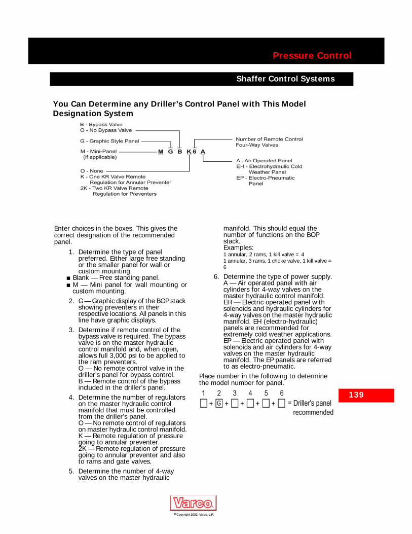
Pressure Control
Shaffer Control Systems
You Can Determine any Driller’s Control Panel with This Model Designation System
139
Enter choices in the boxes. This gives the correct designation of the recommended panel.
1. Determine the type of panel preferred. Either large free standing or the smaller panel for wall or custom mounting.
■ Blank — Free standing panel.■ M — Mini panel for wall mounting or
custom mounting.2. G — Graphic display of the BOP stack
showing preventers in their respective locations. All panels in this line have graphic displays.
3. Determine if remote control of the bypass valve is required. The bypass valve is on the master hydraulic control manifold and, when open, allows full 3,000 psi to be applied to the ram preventers.O — No remote control valve in the driller’s panel for bypass control.B — Remote control of the bypass included in the driller’s panel.
4. Determine the number of regulators on the master hydraulic control manifold that must be controlled from the driller’s panel.O — No remote control of regulators on master hydraulic control manifold.K — Remote regulation of pressure going to annular preventer.2K — Remote regulation of pressure going to annular preventer and also to rams and gate valves.
5. Determine the number of 4-way valves on the master hydraulic
manifold. This should equal the number of functions on the BOP stack.Examples:1 annular, 2 rams, 1 kill valve = 41 annular, 3 rams, 1 choke valve, 1 kill valve = 6
6. Determine the type of power supply.A — Air operated panel with air cylinders for 4-way valves on the master hydraulic control manifold.EH — Electric operated panel with solenoids and hydraulic cylinders for 4-way valves on the master hydraulic manifold. EH (electro-hydraulic) panels are recommended for extremely cold weather applications.EP — Electric operated panel with solenoids and air cylinders for 4-way valves on the master hydraulic manifold. The EP panels are referred to as electro-pneumatic.
Place number in the following to determine the model number for panel.
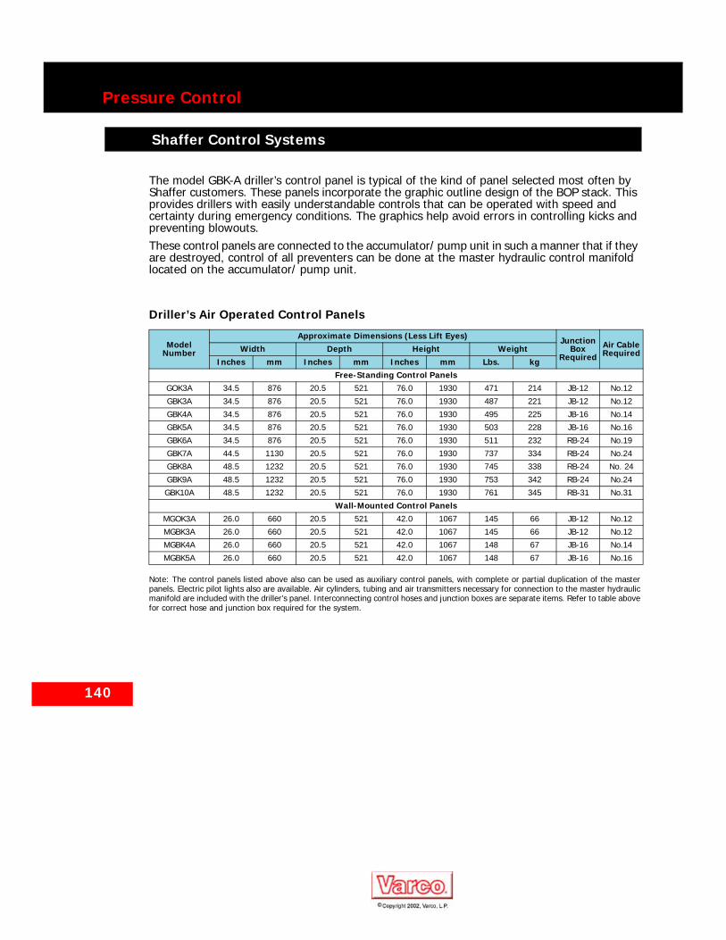
140
Pressure Control
Shaffer Control Systems
The model GBK-A driller’s control panel is typical of the kind of panel selected most often by Shaffer customers. These panels incorporate the graphic outline design of the BOP stack. This provides drillers with easily understandable controls that can be operated with speed and certainty during emergency conditions. The graphics help avoid errors in controlling kicks and preventing blowouts.These control panels are connected to the accumulator/ pump unit in such a manner that if they are destroyed, control of all preventers can be done at the master hydraulic control manifold located on the accumulator/ pump unit.
Note: The control panels listed above also can be used as auxiliary control panels, with complete or partial duplication of the masterpanels. Electric pilot lights also are available. Air cylinders, tubing and air transmitters necessary for connection to the master hydraulicmanifold are included with the driller’s panel. Interconnecting control hoses and junction boxes are separate items. Refer to table abovefor correct hose and junction box required for the system.
Driller’s Air Operated Control Panels
ModelNumber
Approximate Dimensions (Less Lift Eyes) Junction Box
RequiredAir Cable RequiredWidth Depth Height Weight
Inches mm Inches mm Inches mm Lbs. kgFree-Standing Control Panels
GOK3A 34.5 876 20.5 521 76.0 1930 471 214 JB-12 No.12
GBK3A 34.5 876 20.5 521 76.0 1930 487 221 JB-12 No.12
GBK4A 34.5 876 20.5 521 76.0 1930 495 225 JB-16 No.14
GBK5A 34.5 876 20.5 521 76.0 1930 503 228 JB-16 No.16
GBK6A 34.5 876 20.5 521 76.0 1930 511 232 RB-24 No.19
GBK7A 44.5 1130 20.5 521 76.0 1930 737 334 RB-24 No.24
GBK8A 48.5 1232 20.5 521 76.0 1930 745 338 RB-24 No. 24
GBK9A 48.5 1232 20.5 521 76.0 1930 753 342 RB-24 No.24
GBK10A 48.5 1232 20.5 521 76.0 1930 761 345 RB-31 No.31
Wall-Mounted Control PanelsMGOK3A 26.0 660 20.5 521 42.0 1067 145 66 JB-12 No.12
MGBK3A 26.0 660 20.5 521 42.0 1067 145 66 JB-12 No.12
MGBK4A 26.0 660 20.5 521 42.0 1067 148 67 JB-16 No.14
MGBK5A 26.0 660 20.5 521 42.0 1067 148 67 JB-16 No.16

141
Pressure Control
Shaffer Control Systems
Shaffer Control Systems
BOP and Diverter Electro-Pneumatic Control Replacement Upgrade
Driller’s Electric Operated Control PanelsThe Shaffer electric operated panels for the driller’s control of BOPs also incorporate the graphic outline design. This enables drillers to understand quickly the BOP equipment available to them to deal with emergency conditions. The graphics help avoid errors in controlling kicks and preventing blowouts.
Pushbutton light assemblies for each of the BOP stack components indicate the present position of each BOP function. The status lights burn continuously. Operating the pushbuttons signals the electrohydraulic or electropneumatic solenoids at the master hydraulic control manfold on the accumulator/pump unit. This gives almost instantaneous operation of the hydraulic or pneumatic cylinders located on the 4-way valves.Shaffer has been manufacturing the world proven Koomey® BOP Control Systems for over 70 years. As part of our continued commitment to improving this equipment in the field and supporting our existing customers, we have been designing and manufacturing CENELEC Certified Control System Upgrades for use in Hazardous Areas.Special Features:
■ Individually designed to fit existing control system arrangements.
■ PLC Control of all memory and alarm functions.
■ Fully “CENELEC” certified components for use in Hazardous Areas.
■ Stainless steel enclosures to IP65 for environmental protection.
■ Reverse engraved mimic display of BOP stack arrangement.

142
Pressure Control
Shaffer Control Systems
Shaffer Control Systems
Selecting Your Auxiliary Re-mote Control PanelsMost customers select the GARC panel for driller’s control and the MARC mini-panel for remote control.In order to designate the control panel you require, use the following information.
1. Determine the type of panel preferred. Either large self-standing or the smaller panel for wall or unique mounting.
■ GARC — Graphic Air Remote Control.This is free-standing with graphicdisplay of the BOP stack.
■ MARC — Mini Air Remote Control. Thisis wall or custom mounted but withoutgraphic display of the BOP stack.
■ ARC — Air Remote Control. Free-standing but without graphic displayof the BOP stack.
■ MGARC - Mini-Air Remote Control.Wall or custom mounted with graphicdisplay of the BOP stack.
■ GERC — Graphic electric remotecontrol. Wall or custom mounted withgraphic display of the BOP stack. Astand for this panel is optional.
2. Determine the number of 4-way valves on the master hydraulic manifold that would be operated from the remote panel. This should equal the numbers of functions on the BOP stack.
Examples:1 annular, 2 rams, 1 kill valve = 41 annular, 3 rams, 1 choke valve, 1 kill valve = 6
Auxiliary Control Panel Designations

143
Pressure Control
Shaffer Control Systems
Shaffer Control Systems
Electric Operated Auxiliary Remote Control PanelsThese electric operated panels are compact for wall mounting. They are equipped with a graphic display of the BOP stack, a NEMA-12 watertight enclosure, and indicating lights that show the status of the preventers (i.e., open or close). The customer should specify the length of the interconnect cable required to connect the panel to the master hydraulic control manfiold located on the accumulator/pump unit.
Electric Operated Auxiliary Remote Control Panels
Model NumberOverall Approximate Dimensions
Width Depth Height WeightInches mm Inches mm Inches mm Lbs. Kg
GERC-1 24.0 610 10.5 268 24.0 610 52 24
GERC-2 24.0 610 10.5 268 24.0 610 52 24
GERC-3 24.0 610 10.5 268 24.0 610 53 24
GERC-4 24.0 610 10.5 268 24.0 610 53 24
GERC-5 24.0 610 10.5 268 24.0 610 54 25
GERC-6 24.0 610 10.5 268 24.0 610 54 25
GERC-7 24.0 610 10.5 268 24.0 610 55 25
GERC-8 24.0 610 10.5 268 24.0 610 55 25
GERC-9 24.0 610 10.5 268 24.0 610 56 25
144
Pressure Control
Shaffer Control Systems
Shaffer Control Systems
Miscellaneous ControlsFree Standing Hydraulic Diverter ControlsShaffer provides a variety of hydraulic diverter controls. Each can be mounted integrally with the BOP hydraulic control manifold or can be mounted separately on its own skid. You have a choice of 3/4” or1 1/2” regulators and 1” or 1 1/2” 4-way control valves for diverter controls. The choice of size depends upon fluid requirements.Hydraulic diverter controls also can include a heavy duty gauge and an air cylinder for remote control operations. If remote pressure regulation is desired, diverter controls are furnished with an air pilot regulator. This regulator features a unit/remote selector valve and a pneumatic transmitter.Hydraulic diverter controls also can be supplied in a free-standing panel design. This panel, with graphic representation of the diverter installation, includes pressure regulators, gauges, and a control valve necessary for diverter operation. A bladder type accumulator is furnished as a surge dampener. Air cylinders can be included for remote operation. Hydraulic supply and return connections — as well as connections for remote panel operation — are positioned conveniently.

145
Pressure Control
Shaffer Auxiliary Equipment
Shaffer Auxiliary Equipment
Complete Shutoff ChokeSystemA Shaffer drilling choke system provides fast, accurate well control through one or two chokes operated remotely from the rig floor. Fluids can be circulated from the wellbore while holding any desired back pressure rating of the choke.Chokes are available for 5,000, 10,000 and 15,000 psi at up to 300° F, suitable for H2S service.
Choke and Kill ManifoldsShaffer choke and kill manifolds are manufactured for diverse applications from simple low pressure environments to extreme sour gas service. Shaffer’s wide array of fixed, hand-adjustable and remotely-adjustable chokes can be furnished in a 5,000, 10,000 and 15,000 psi manifold — with or without a buffer chamber.
Best ChokesVarco Best chokes come in various sizes and working pressures and, depending on the choice and application, can be used for extremely high pressure wells. It comes equipped with API flanges in working pressures of 5,000, 10,000 and 15,000 psi.Best Maximum Performance Cage (MPC) chokes provide extended life and superior performance from Best’s cage trim design. Safety and cost effective operation are improved through the use of Best’s Wear Monitor. The reliability of the Model VBS-100 stepping actuator has been proven through extensive laboratory and field testing.

146
Pressure Control
Shaffer Riser String Packages
Shaffer Riser String Packages
Shaffer Riser SpiderThe Shaffer riser spider is designed to support the riser string when running and retrieving through the rotary table. The split-design spider is hydraulically operated, compatible with all rotary tables, and can support up to 3.5 million pounds.
Marine Riser SystemsShaffer offers a complete range of marine riser systems from shallow water to ultra deep drilling applications including riser analysis. By analyzing all design variables and drilling condition parameters, we ensure that the product is highly reliable, durable and cost effective.
Ultra Deep Water RiserShaffer has lead new riser design with the introduction of the DT-2 2-million lb. dog-type riser connections. As drilling depths have increased, Shaffer has introduced the first 3.5 million lb. bolted-type flange connector, the Type FTH. It is designed for applications that meet API 16R class H. Operation of the FTH riser connector is simple and easy with current available riser makeup tool. With uni-directional field-replaceable, improved J-lock retention slot seal sub, the FTH riser requires minimum maintenance.
Riser Fillup ValveShaffer’s riser fillup valve utilizes a simple and reliable design to prevent the collapse of the riser due to the evacuation of the drilling fluid. The fillup valves are automatically actuated when mud level pressure falls below a specified minimum. Shaffer riser fillup valves are self-contained and independent of control lines.
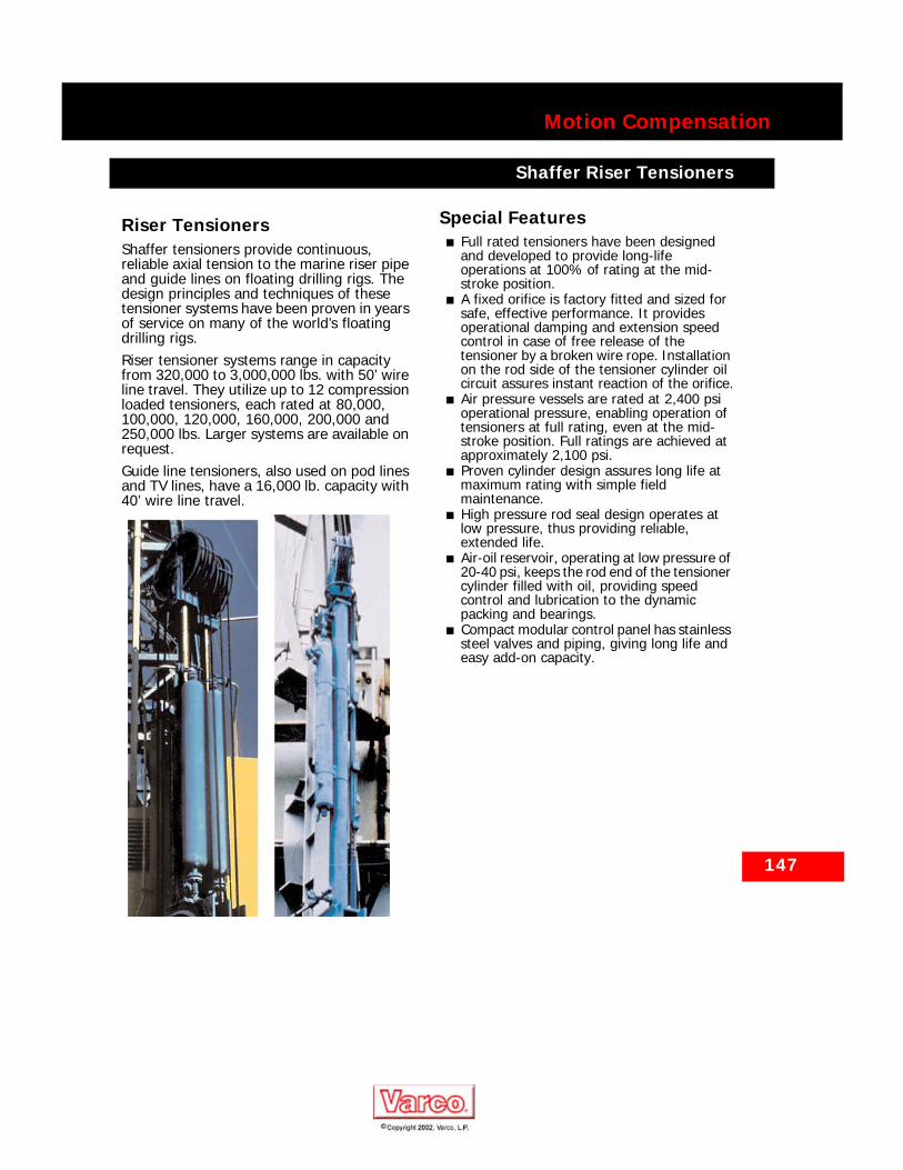
147
Motion Compensation
Shaffer Riser Tensioners
Motion CompensationShaffer Riser Tensioners
Riser TensionersShaffer tensioners provide continuous, reliable axial tension to the marine riser pipe and guide lines on floating drilling rigs. The design principles and techniques of these tensioner systems have been proven in years of service on many of the world’s floating drilling rigs.Riser tensioner systems range in capacity from 320,000 to 3,000,000 lbs. with 50’ wire line travel. They utilize up to 12 compression loaded tensioners, each rated at 80,000, 100,000, 120,000, 160,000, 200,000 and 250,000 lbs. Larger systems are available on request.Guide line tensioners, also used on pod lines and TV lines, have a 16,000 lb. capacity with 40’ wire line travel.
Special Features■ Full rated tensioners have been designed
and developed to provide long-life operations at 100% of rating at the mid-stroke position.
■ A fixed orifice is factory fitted and sized for safe, effective performance. It provides operational damping and extension speed control in case of free release of the tensioner by a broken wire rope. Installation on the rod side of the tensioner cylinder oil circuit assures instant reaction of the orifice.
■ Air pressure vessels are rated at 2,400 psi operational pressure, enabling operation of tensioners at full rating, even at the mid-stroke position. Full ratings are achieved at approximately 2,100 psi.
■ Proven cylinder design assures long life at maximum rating with simple field maintenance.
■ High pressure rod seal design operates at low pressure, thus providing reliable, extended life.
■ Air-oil reservoir, operating at low pressure of 20-40 psi, keeps the rod end of the tensioner cylinder filled with oil, providing speed control and lubrication to the dynamic packing and bearings.
■ Compact modular control panel has stainless steel valves and piping, giving long life and easy add-on capacity.
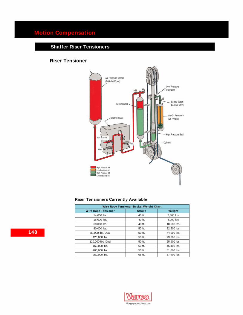
148
Motion Compensation
Shaffer Riser Tensioners
Riser Tensioner
Riser Tensioners Currently Available
Wire Rope Tensioner Stroke/Weight ChartWire Rope Tensioner Stroke Weight
14,000 lbs. 40 ft. 2,800 lbs.
16,000 lbs. 40 ft. 4,000 lbs.
60,000 lbs. 40 ft. 18,500 lbs.
80,000 lbs. 50 ft. 22,500 lbs.
80,000 lbs. Dual 50 ft. 44,000 lbs.
120,000 lbs. 50 ft. 29,800 lbs.
120,000 lbs. Dual 50 ft. 55,900 lbs.
160,000 lbs. 50 ft. 45,400 lbs.
200,000 lbs. 50 ft. 51,000 lbs.
250,000 lbs. 66 ft. 67,400 lbs.

149
Motion Compensation
Shaffer Riser Recoil Systems
Shaffer Riser Recoil Systems
Riser RecoilRiser recoil control systems must address two potential problems associated with emergency disconnection of deep water drilling risers:
■ Preventing a collision between the lower marine riser package (LMRP) and the stack,
■ Controlling any impact between the riser and the vessel.
Since the solution to either of these problems has an adverse affect on the other, these conditions must be considered together. Therefore, to avoid a collision between the stack and the LMRP when the vessel heaves downward, the riser recoil control system must allow riser velocity to quickly move the LMRP away from the stack. At the same time, the system must also limit riser velocity and kinetic energy to control impact between the riser and the vessel. Finally, these conditions must occur within the stroke limits of the slip joint.Shaffer’s riser recoil control system consists of both standard and specially designed actuated valves. These valves are arranged to reduce maximum riser energy as well as tensioner terminal velocity by isolating a portion of the system energy and limiting pressure drop available to the cylinder through a restricted port.By reducing the volume of power air pressure vessels (APVs) accessible to the tensioners, the energy available for transfer to the riser and, therefore, a maximum riser energy, is reduced. This reduction is accomplished by closing actuated valves on preselected APVs. Reducing the APV volume does not affect acceleration of the riser at the critical time immediately after disconnect because no pressure change is introduced. As the LMRP moves clear of the stack, cylinder pressure decreases, thus reducing acceleration of the riser.
Maximum tensioner velocity is controlled by Shaffer designed valves installed between the hydraulic fluid accumulator and the inlet port of each tensioner. When actuated, these valves place an appropriate size restriction in the tensioner cylinder inlet flow path. This restriction introduces a pressure drop proportional to the velocity of the fluid passing through the port. The reduction of pressure decreases the overpull. This limits maximum riser velocity to an acceptable level. The replaceable restriction also provides more flexibility to comply with each customer’s specific requirements. In order to coordinate the operation of the riser recoil control system with riser disconnect, Shaffer’s riser recoil control system is designed to be triggered by an external signal, usually from the vessel’s emergency disconnect system (EDS). The system can be adjusted to operate immediately when triggered or after a preset delay. The riser recoil control system can also be triggered from alternate sources or from combinations of sources (e.g. EDS and a heave sensor) as required by the customer.Selection of the correct riser recoil control system depends on the following criteria:
■ Maximum anticipated heave state during a riser disconnect,
■ Riser weight,■ Overpull,■ Operational procedures.
Contact your Shaffer sales representative for more information on riser recoil control system requirements.

150
Motion Compensation
Shaffer Drill String Compensators
Shaffer Drill String Compensators
Drill String CompensatorsThe Shaffer Drill String Compensator (DSC) is the most popular system of its kind in use today. It is mounted between the traveling block and hook. This isolates the heaving motion of the vessel from the drill string. It minimizes wear between the drill string and the blowout preventer, marine riser and casing strings. Shaffer DSCs, like other Shaffer motion compensation equipment, use the hydro-pneumatic operating principle. DSCs are furnished with operating stroke lengths of 15, 18, 20 or 25 feet, depending on rig design and application. They can be manufactured to meet ASME, ABS, USCG, DNV, and other applicable codes.
600K
During drilling operations, the Shaffer DSC keeps the drill bit on the bottom of the hole within the weight limits set by the driller. For other operations, the system compensates for rig motion, maintaining a position relative to the ocean floor.As the rig heaves upward, the compensator cylinders retract and the hook moves downward relative to the drill floor, while remaining at a constant level relative to the earth. The cylinder piston compresses the air through the hose into the air pressure vessels to maintain the preset tension level.As the rig heaves downward, air from the air pressure vessels expands into the compensator cylinder, and the system works in reverse.
400K

151
Motion Compensation
Shaffer Drill String Compensators
Drill String Compensator (In-Line)

152
Motion Compensation
Shaffer Drill String Compensators
Shaffer DSCs, by compensating for vertical heave motion of the drilling vessel, minimize wear inside the BOP stack and on the marine riser and casing string. Wear on the ram BOP seals and annular BOP elements also is minimized. There is virtually no motion of the drill string while the blowout preventers are closed. In addition, the BOP stack can be landed without abrupt motion changes, and the setting of the packers and drill stem test tools is easier.
Other Special Features Include:■ Constant bit weight control — You get
higher penetration rates and longer drill bit life.
■ Faster response time — The Shaffer air system, in contrast with a hydraulic system, eliminates system shock pressure and permits faster compensation action.
■ Complete control by driller — Console at driller’s station provides full control of compensator load and monitoring of stroke position. Mechanical lock bar is activated at console to lock the hook and traveling block together — a foolproof method to prevent dropping the load accidentally. The bar cannot be disengaged unless the tension setting exceeds the hook load.
■ Extended stroke operation — This delivers 25 feet of compensation from 12 feet of cylinder stroke, reducing installation height and the wear on bearings and packing.
■ Full rated compensation at lower pressure — Although other systems require 3,500 psi to equal Shaffer system ratings, the Shaffer system achieves 400,000, 600,000 or 800,000 lb. full rated compensation with only 2,400 psi maximum psi. Shaffer air pressure vessels and system components are manufactured to operate at 2,400 psi.
■ Efficient air coupling between the compensator and air pressure vessels — This reduces pressure drop from line flow losses. There is less hook load variation with stroke action.
■ Four spiral-wire — wrapped air hoses — Long life is assured. Concentric stainless steel cables prevent loose end movement in case of hose failure. Operation is possible with three hoses if one should fail. In-line air safety valves at each end of each air hose close instantly in the remote event of an air hose failure. This would prevent air pressure (tension) loss and any possibility of damage to equipment or injury to personnel.
■ Compression-loaded cylinder design — This has evolved from more than 26 years of experience with riser tension applications. You get efficient operation with controlled loading and long life. There is minimum cylinder friction because only one set of dynamic packing is exposed to high pressure and is protected and lubricated by the oil circuit. This results in less hook load variation with stroke action.
■ Long stroke design for rod end cushion — This assures safe deceleration of cylinder in the event of free release under load.
■ Blind end cushion — This eliminates mechanical shock otherwise encountered when the traveling block is raised to put full string weight on the hook.
■ Patented speed limiting valve — This assures safe operation by controlling and limiting the maximum speed at which the cylinder may extend. This in-line valve closes when the maximum safe rod speed is exceeded, preventing damage to cylinder and adjacent equipment.
■ Low pressure air-oil reservoir — Operating at 20-40 psi, this keeps the cylinder rod end filled with oil for speed control and continuous lubrication and damping.
■ Flexible linkage between cylinder and hook — The leaf chain design provides an efficient, flexible power linkage and assures concentric loading of the cylinder. Lateral loads are eliminated. Equipment life is extended.
■ Hydraulic locking option available — The Shaffer 600K/800K DSC offers an option to permit locking of the cylinders in any stroke position. In a locked position, the 600K DSC can support a static load up to 600,000 lbs. The 800K DSC can support a static load up to 800,000 lbs.
■ Mechanical locking of hook plate to DSC main frame allows static load capabilities of 1,500,000 lbs. on 600K DSC and up to 2,000,000 lbs. on 800K DSC.
■ Rigid DSC connection to traveling block — This feature of the 600K DSC increases stability, reduces weight by 2,900 lbs., and increases clearance in the derrick by about 17 1/2”. Also available for 800K DSC.
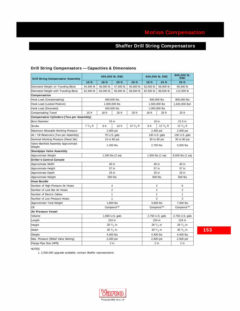
153
Motion Compensation
Shaffer Drill String Compensators
Drill String Compensators — Capacities & Dimensions
Drill String Compensator Assembly400,000 lb. DSC 600,000 lb. DSC 800,000 lb.
DSC15 ft 18 ft 20 ft 25 ft 18 ft 25 ft 25 ft
Estimated Weight on Traveling Block 44,400 lb 46,000 lb 47,600 lb 50,600 lb 62,000 lb 68,000 lb 90,500 lb
Estimated Weight with Traveling Block 62,400 lb 64,000 lb 65,600 lb 68,600 lb 82,500 lb 88,500 lb 112,000 lb
CompensationHook Load (Compensating) 400,000 lbs 600,000 lbs 800,000 lbs
Hook Load (Locked Position) 1,000,000 lbs 1,500,000 lbs 1,625,000 lbs1
NOTES:1. 2,000,000 upgrade available, contact Shaffer representative.
Hook Load (Extended) 400,000 lbs 1,000,000 lbs
Compensating Travel 15 ft 18 ft 20 ft 25 ft 18 ft 25 ft 25 ft
Compensator Cylinders (Two per Assembly)Bore Diameter 15 in 19 in 21.5 in
Stroke 7 1/2 ft 9 ft 10 ft 12 1/2 ft 9 ft 12 1/2 ft 12 1/2 ft
Maximum Allowable Working Pressure 2,400 psi 2,400 psi 2,400 psi
Air / Oil Reservoirs (Two per Assembly) 70 U.S. gals 130 U.S. gals 130 U.S. gals
Nominal Working Pressure (Panel Set) 15 to 80 psi 30 to 80 psi 30 to 80 psi
Valve Manifold Assembly Approximate Weight 1,200 lbs 2,700 lbs 3,000 lbs
Standpipe Valve AssemblyApproximate Weight 1,200 lbs (2 ea) 1,500 lbs (1 ea) 8,500 lbs (1 ea)
Driller’s Control ConsoleApproximate Width 40 in 40 in 40 in
Approximate Height 57 in 57 in 57 in
Approximate Depth 25 in 25 in 25 in
Approximate Weight 500 lbs 500 lbs 500 lbs
Hose BundleNumber of High Pressure Air Hoses 4 4 6
Number of Lock Bar Air Hoses 2 2 2
Number of Electric Cables 1 1 1
Number of Low Pressure Hoses 1 3 3
Approximate Total Weight 1,800 lbs 3,600 lbs 7,000 lbs
Oil Compenol™ Compenol™ Compenol™
Air Pressure VesselVolume 1,650 U.S. gals 2,750 U.S. gals 2,750 U.S. gals
Length 224 in 224 in 224 in
Height 28 1/2 in 28 1/2 in 28 1/2 in
Width 30 1/2 in 30 1/2 in 30 1/2 in
Weight 4,400 lbs 4,400 lbs 4,400 lbs
Max. Pressure (Relief Valve Setting) 2,400 psi 2,400 psi 2,400 psi
Flange Pipe Size (NPS) 2 in 2 in 2 in

154
Motion Compensation
Shaffer Drill String Compensators
Drill String Compensator — Upgrade from 400K TO 600KThe 400K Rucker Drill String Compensator (DSC) can now be upgraded to achieve a compensating capacity of 600,000 lbs. in a 400K frame.
Why Upgrade?The modern need for an increase in compensating capacity is driven by the following considerations:
■ Deeper waters and deeper drilling depths increase hook loads.
■ Horizontal or deviated wells result in increased drill string/casing weights for ‘medium’ vertical depth wells.
■ Addition of top drive or other equipment increased the dead weight on the hook, thereby reducing the net compensating capacity.
■ Operational safety concerns prefer the stack to be landed with one controlling handle on the drill string compensator rather than relying on coordination between the compensator and riser tensioner controls.
Options for an UpgradeOptions for upgrading a 400K DSC have historically included installing a 600K DSC or a CMC. The 400K to 600K upgrade was developed as a less expensive option to consider. This upgrade maintains the 1,000,000 lb. mechanically locked hook load capabilities of the existing compensator. It increases the rated hook load capacity from 400,000 lbs. to 600,000 lbs.
How is it Done?The upgrade package is designed to increase the hook load capacity to 600,000 lbs. while minimizing the number of components being replaced.The significant components replaced include:
■ Cylinders of a larger diameter installed within the existing main frame.
■ Chains are replaced with 500K chain.■ Fork blocks, chain adjustment rods, cross
beam blocks, sheaves, and hook frame lifters are upgraded.
■ A new hook load gauge reflecting the higher capacity is provided for the driller’s console.
■ Upgrade piping.■ Miscellaneous hardware.
The upgraded system continues to operate at the existing design pressure. The new cylinders incorporate fewer component parts, special low friction packing, and rod end volume designed to use the existing air-oil reservoirs.Contact your Shaffer sales representative to further discuss upgrading your 400K DSC to 600K.

155
Motion Compensation
Shaffer Traveling Blocks
Shaffer Traveling Blocks
“Flat” Traveling Block
“Standard” Traveling Block
Traveling Blocks
Description No. of Sheaves Sheave Diameter (Inches)
Rope Size Diameter (Inches)
400K, Integral DSC 6 60 1.50
750T, Integral DSC 7 65 1.63
750T, Integral DSC 7 60 1.50
750T, Integral DSC 7 66 1.50
750T, Integral DSC 7 60 1.50
750T, Integral DSC 7 65 1.63
750T, Integral DSC 7 65 1.75
750T, Integral DSC 8 65 1.50
825T, Integral DSC 8 65 1.75
825T, Integral DSC 8 78 2.00
1000T, Integral DSC 8 68 2.00
750T, Inline Bail 8 68 1.75
1000T, Inline Bail 7 78 2.00
1000T, Inline Bail 8 68 2.00
500T, Std. Bail 6 60 1.63
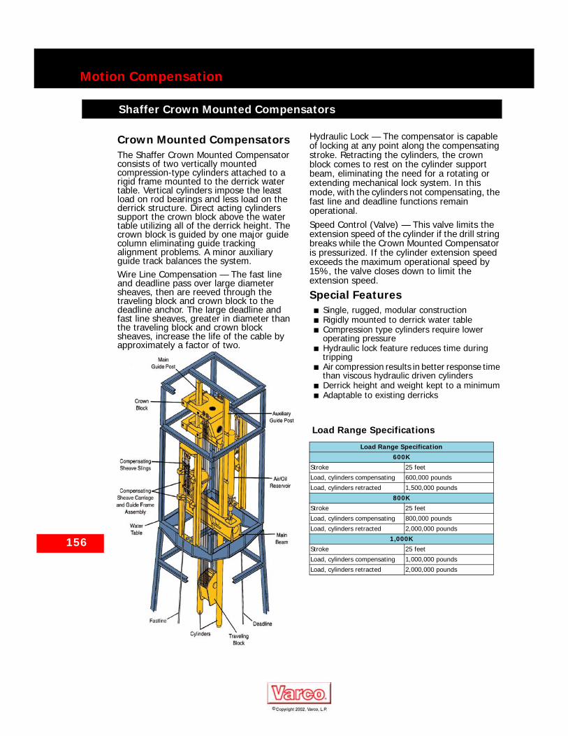
156
Motion Compensation
Shaffer Crown Mounted Compensators
Shaffer Crown Mounted Compensators
Crown Mounted CompensatorsThe Shaffer Crown Mounted Compensator consists of two vertically mounted compression-type cylinders attached to a rigid frame mounted to the derrick water table. Vertical cylinders impose the least load on rod bearings and less load on the derrick structure. Direct acting cylinders support the crown block above the water table utilizing all of the derrick height. The crown block is guided by one major guide column eliminating guide tracking alignment problems. A minor auxiliary guide track balances the system.Wire Line Compensation — The fast line and deadline pass over large diameter sheaves, then are reeved through the traveling block and crown block to the deadline anchor. The large deadline and fast line sheaves, greater in diameter than the traveling block and crown block sheaves, increase the life of the cable by approximately a factor of two.
Hydraulic Lock — The compensator is capable of locking at any point along the compensating stroke. Retracting the cylinders, the crown block comes to rest on the cylinder support beam, eliminating the need for a rotating or extending mechanical lock system. In this mode, with the cylinders not compensating, the fast line and deadline functions remain operational.Speed Control (Valve) — This valve limits the extension speed of the cylinder if the drill string breaks while the Crown Mounted Compensator is pressurized. If the cylinder extension speed exceeds the maximum operational speed by 15%, the valve closes down to limit the extension speed.
Special Features■ Single, rugged, modular construction■ Rigidly mounted to derrick water table■ Compression type cylinders require lower
operating pressure■ Hydraulic lock feature reduces time during
tripping■ Air compression results in better response time
than viscous hydraulic driven cylinders■ Derrick height and weight kept to a minimum■ Adaptable to existing derricks
Load Range Specifications
Load Range Specification600K
Stroke 25 feet
Load, cylinders compensating 600,000 pounds
Load, cylinders retracted 1,500,000 pounds
800KStroke 25 feet
Load, cylinders compensating 800,000 pounds
Load, cylinders retracted 2,000,000 pounds
1,000KStroke 25 feet
Load, cylinders compensating 1,000,000 pounds
Load, cylinders retracted 2,000,000 pounds
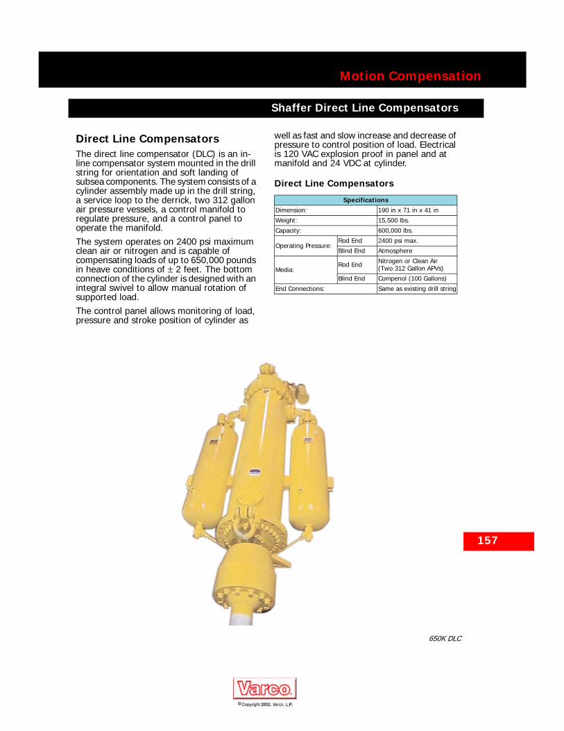
Motion Compensation
Shaffer Direct Line Compensators
Shaffer Direct Line Compensators
Direct Line CompensatorsThe direct line compensator (DLC) is an in-line compensator system mounted in the drill string for orientation and soft landing of subsea components. The system consists of a cylinder assembly made up in the drill string, a service loop to the derrick, two 312 gallon air pressure vessels, a control manifold to regulate pressure, and a control panel to operate the manifold.The system operates on 2400 psi maximum clean air or nitrogen and is capable of compensating loads of up to 650,000 pounds in heave conditions of ± 2 feet. The bottom connection of the cylinder is designed with an integral swivel to allow manual rotation of supported load.The control panel allows monitoring of load, pressure and stroke position of cylinder as
well as fast and slow increase and decrease of pressure to control position of load. Electrical is 120 VAC explosion proof in panel and at manifold and 24 VDC at cylinder.
Direct Line Compensators
SpecificationsDimension: 190 in x 71 in x 41 in
Weight: 15,500 lbs.
Capacity: 600,000 lbs.
Operating Pressure:Rod End 2400 psi max.
Blind End Atmosphere
Media:Rod End Nitrogen or Clean Air
(Two 312 Gallon APVs)
Blind End Compenol (100 Gallons)
End Connections: Same as existing drill string
157
650K DLC