Embed Size (px)
Citation preview

BOP Handling Systems25 to 200 metric tons Lifting Capacity

1
1. BOP Handling Systems – Overview ......................................................................3
2. BOP Handling Systems – Selection Chart ............................................. 4
3. Hercu-Link™ Air BOP Handling Systems (50 to 200 tons Capacity)
Standard Features and Options ........................................................................ 5
Specifications and Performance of Piston Motor Drive .................................. 6
Model Driver ...................................................................................................... 7
Dimensions and Drawings ......................................................................... 12-13
4. Liftchain® BOP Handling Systems (25 to 200 tons Capacity)
Standard Features and Options ........................................................................ 8
Liftchain® Air BOP Handling Systems
Specifications and Performance of Gear Motor Drive ............................. 9
Model Driver ........................................................................................... 11
Dimensions and Drawings ................................................................ 14-18
Liftchain® Hydraulic BOP Handling Systems
Specifications and Performance ............................................................. 10
Model Driver ........................................................................................... 11
Dimensions and Drawings ................................................................ 14-18
5. Engineered Solutions
BHS150M and BHS200M series ...................................................................... 19
ULBS100LCA4 series (Ultra-low headroom design) ....................................... 19
6. Contact Information
Worldwide Locations ....................................................................................... 20
Table of Contents
2
ingersollrandproducts.com/lifting
Certificate No. FM53539 Certificate No. QUAL/1991/309e
For over 30 years Ingersoll Rand has designed, manufactured, and serviced hundreds of Blowout Preventer Handling Systems for all the major drilling contractors and oil companies in the industry.
Our familiarity with this complex and critical lifting application enables us to provide the type of equipment, engineering support, and certifications that these projects require.
The design of our BOP Handling Systems reflects the years of experience we’ve gained by providing equipment for the harshest environments and applications around the world. Our Oilfield Tough systems feature compact modular designs, robust “bulletproof” gearboxes, powerful air or hydraulic motors, large diameter load chain, and all steel/cast iron construction which provides increased safety, rugged reliability, enhanced control, and reduced maintenance.
Our commitment to safety and quality combined with our long experience with difficult lifting applications allows us to provide our clients with the safest and most cost-effective solutions possible.
The Ingersoll Rand AdvantageOur BOP Handling Systems are designed to meet or exceed the specifications of one or more of the following regulatory bodies; the Norwegian Petroleum Directorate (NPD), UK HSE, Lloyds Register of Shipping (LRS), Det Norske Veritas (DNV), and American Bureau of Shipping (ABS) for the oilwell drilling industry.
All Ingersoll Rand BOP handling systems are designed and built in ISO9001certified factories.
ISO 9001 certified manufacturing and service facilities
5:1 design factor combined with all steel and cast iron construction to withstand the brutal environmental and mechanical challenges of the job.
Automatic multi-disc oil bath motor brakes that engage instantly the moment the controls are released.
High efficiency planetary gearboxes that are fully sealed to exclude contaminants.
Space saving modular designs require no deck space, offer low headroom and improved end approach. Ultra-low headroom models are available for applications with severe envelope restrictions.
Air and hydraulic powered models to choose from, including high-torque radial piston and compact (lube-free) gear type air motors. Air motors provide built-in overload protection since they will stall without damaging hoist.
Smooth, precise, and safe load control with variable speed pendent control.
Rugged corrosion resistant load chain in 16, 22, and 32 mm sizes has greater elongation and therefore, is more resistant to shock loading. The large links provide for easier external inspection, excellent resistance to abrasion, and will last indefinitely when properly maintained.
True vertical lift which enhances load control characteristics and safety.
Articulated trolleys accommodate limited side pulling as BOP stack is being lifted.
Engineered options � Rack and pinion trolley drive option for positive traction and improved horizontal load control.Severe duty packages available for cold weather, marine, and explosion-proof environments including ATEX. �Remote control pendents and consoles. �Spark and corrosion resistant components. � Air and hydraulic festooning systems. �Trolleys for custom fabricated beams. � Clevis and shackle bottom block assemblies. � Low pressure 4 bar (57psi) applications. �
BOP Handling Systems OVERVIEW
Ove
rvie
w

3
**Rated capacity Model Number Number of Chain Falls Max. lifting speed Minimum Headroom (tons) per hoist m/min (ft/min) mm (in.)
Hercu-Link™ Air BOP Handling Systems (Piston motor drive)
50 BHS50M 2 1.2 (4) 1040 (40.94)
75 BHS75M 3 0.8 (2.5) 1243 (48.94)
100 BHS100M 4 0.6 (2) 1346 (53)
150 BHS150M 3 0.7 (2.5) –
200 BHS200M 4 0.6 (2) –
Liftchain® Air BOP Handling Systems (Gear motor drive)
25 BS25LCA2P 2 0.8 (2.63) 1128 (44.41)
30 BS30LCA3P 3 0.6 (1.97) 1242 (48.9)
36 BS36LCA3P 3 0.5 (1.64) 1242 (48.9)
40 BS40LCA4P 4 0.4 (1.30) 1290 (50.79)
50 BS50LCA2P 2 1.6 (5.25) 976 (38.42)
50 BS50LCA4P 4 0.4 (1.30) 1290 (50.79)
75 BS75LCA3P 3 1.1 (3.60) 1170 (46.06)
100 BS100LCA4P 4 0.8 (2.60) 1392 (54.8)
150 BS150LCA3P 3 0.4 (1.30) 1845 (72.64)
200 BS200LCA4P 4 0.3 (0.98) 1901 (74.84)
Liftchain® Hydraulic BOP Handling Systems
25 BS25LCH2P 2 2.8 (9.19) 1128 (44.41)
30 BS30LCH3P 3 1.9 (6.23) 1242 (48.9)
36 BS36LCH3P 3 1.86 (6.1) 1242 (48.9)
40 BS40LCH4P 4 1.35 (4.1) 1290 (50.79)
50 BS50LCH2P 2 2.27 (7.45) 976 (38.42)
50 BS50LCH4P 4 1.35 (4.1) 1290 (50.79)
75 BS75LCH3P 3 1.51 (4.95) 1170 (46.06)
100 BS100LCH4P 4 1.13 (3.7) 1392 (54.8)
150 BS150LCH3P 3 0.48 (1.57) 1845 (72.64)
200 BS200LCH4P 4 0.36 (1.18) 1901 (74.84)
BOP Handling Systems SELECTION CHART
**All BOP Handling Systems are comprised of two trolley-mounted hoists; each of which is rated at one-half the complete system capacity.
Selection C
hart

4
ingersollrandproducts.com/lifting
BHS50M (50‑ton system) after storage of Blowout Preventer for periodic maintenance.
BHS100M (100‑ton system) in the process of deploying Blowout Preventer stack
Hercu-Link™ Air BOP Handling Systems STANDARD FEATURES AND OPTIONS of Piston Motor Drive – 50 to 200 tons Lifting Capacity
Designed to meet or exceed specifications of one or more of the following regulatory bodies – the Norwegian Petroleum Directorate (NPD), UK HSE, Lloyds Register of Shipping (LRS), Det Norske Veritas (DNV), and American Bureau of Shipping (ABS) for the oilwell drilling industry.
Standard FeaturesRadial piston air motor – hoist and trolley y5:1 design factor yAll steel construction yAutomatic Fail- Safe, multi disc, motor brake on hoist yArticulated trolley allows limited side pulling operations on yspecial modelsFully enclosed planetary gear box yCompact modular design yCorrosion resistant load chain y9m (30 ft) height of lift standard on all models yBottom block mounted on bearing with external lubrication ypoint and water drainAccu-Trol™ pendent with “emergency stop/start” feature and y9m (30 ft) pendent hoseLimit switch for upper and lower over-travel protection. yLifting lugs for easy installation yFilter-Lubricator air preparation package mounted on unit yCorrosion resistant Marine 812 finish paint yGalvanized steel chain container yTrolley guide rollers, rubber bumpers, and rail sweeps yManufacturer test certificate and maintenance manual yExhaust mufflers y
OptionsVariable lengths of lift and pendent control hose ySpark and corrosion resistant (S y •COR•E) packagesRack and pinion trolley drive for positive traction yClevis and shackle attachment in lieu of bottom hook yAir or hydraulic festooning systems yTrolleys for shipyard fabricated beams yCE compliant models including overload protection and ymain emergency stop deviceCorrosion resistant Marine 812-X paint system ySandblast and carbozinc (primer only) yCustom paint coating systems per owners specifications yCustom designed air control consoles y4 bar (57 psi) application models y
Her
cu-L
ink™
A
ir

5
Standard Equipment:
Trolley Bumpers
Muffler
Limit Switch
Air prep package
Piston Motor Trolley
Disc brake system Accu‑Trol™ pendent handle
Corrosion resistant load chain
Galvanized steel chain container
Hercu-Link™ Air BOP Handling SystemsSPECIFICATIONS AND PERFORMANCE of Piston Motor Drive – 50 to 200 tons Lifting Capacity
WARNING:
This equipment is not to be used for lifting, supporting or transporting people, or lifting or supporting loads over people.
Hoist SpecificationsModel System Standard lift/ Speed of hoist Hoist Air inlet Chain Chain wt./lineal Chain Net weightNo. capacity Pendent drop lift lower motor NPT Size m (ft) of lift falls per of system (tons) m ft m/min fpm m/min fpm hp cfm in. mm kg lbs hoist kg lbs
BHS50M 50 9 30 1.2 4 1.8 6 9.4 280 1 22 x 66 21 47 2 2616 5750BHS75M 75 9 30 0.8 2.5 1.1 3.8 9.4 280 1 22 x 66 32 71 3 2844 6250BHS100M 100 9 30 0.6 2 0.9 3 9.4 280 1 22 x 66 43 94 4 3526 7750BHS150M 150 9 30 0.7 2.5 - - 25 700 1-1/2 32 x 90 68 151 3 4527 9950 BHS200M 200 9 30 0.6 2 - - 25 700 1-1/2 32 x 90 91 201 4 5005 11000
Notes: Air supply hose size must be a minimum 0.25 inch larger dia. than air inlet size. Performance figures are at 7.3 bar (105 psi) air pressure.
Trolley SpecificationsModel No. of pairs Flange Wheel tread Wheel loading Min. inside Trolley SpeedNo. of wheels adjustment diameter per pair curve radius motor of Trolley per beam mm in. mm in. kg lbs mm in. hp cfm m/min fpm
BHS50M 4 152-203 6-8 175 6.88 6552 14400 - - 1.6 65 0-12 0-40BHS75M 4 203-254 8-10 229 9 9896 21750 - - 1.6 65 0-12 0-40BHS100M 4 203-254 8-10 229 9 13104 28800 - - 1.6 65 0-12 0-40BHS150M 8 203-254 8-10 229 9 9896 21750 - - 1.6 65 0-12 0-40BHS200M 8 203-254 8-10 229 9 13104 28800 - - 1.6 65 0-12 0-40
(1) Without trailing trolley or with articulated trolley.
Hercu-Link™
A
ir

6
ingersollrandproducts.com/lifting
How to OrderSpecify the complete model as shown. Specify beam size, type and flange width.
Example: BHS50MA6-30-30-KR
BHS = Blowout Preventer Handling System
M = Piston Motor Trolley
RT = Rack and Pinion Trolley Drive for Tapered Beam Flange
RF = Rack and Pinion Trolley Drive for Flat Beam Flange
A = standard
B = 2” extension
C = 4" extension
D = 6” extension
5 = 1 Mtr. Pendent (2 button w/on-off)
6 = 2 Mtr. Pendent (4 button w/on-off)
7 = 3 Mtr. Pendent (6 button w/on-off)
XX = Length of lift in feet
tons lbs # of hoists x cap.
50 = 110,000 (2 x 25 tons)
75 = 165,000 (2 x 37.5 tons)
100 = 220,000 (2 x 50 tons)
150 = 330,000 (2 x 75 tons)
200 = 440,000 (2 x 100 tons)
WARNING: Standard Hercu-Link™ hoists purchased for B.O.P. Handling Systems will void the warranty. They are not designed for this type of application.
XX = Pendent hose drop and/or hand chain drop in feet
KR30306AM50BHS
C1M3 = ABS minus 20 degree C design temperature (tD) C2M3 = DNV minus 20 degree C design temperature (tD) K = Clevis (in place of bottom hook) M1 = Per DIN 50049/EN10204 Para 2.2 “Typicals” M2 = Per DIN 50049/EN10204 Para 3.1b actual per product as purchased M3 = Per DIN 50049/EN10204 Para 3.1b actual per product as delivered in final condition N4 = American Bureau of Shipping “Certification of Drilling Systems” N5 = Det Norske Veritas “DNV-OS-E101 Drilling Plant" P1 = Marine 812-X Paint System P2 = Marine 812-X Paint System (isocyanate free paint system) R = Copper plated (S•COR•E package) The product will be equipped with copper plated load hook(s) and trolley wheels W1 = ABS witness test W2 = DNV witness test W3 = LRS witness test W4 = Customer witness test -CE = Compliance with European Machinery Directive
Notes:M1 - Material traceability certificates according to EN 10204 (Ex DIN 50049) 2.2 on load bearing parts. This conformity document affirms (by the manufacturer) that parts are in compliance with the requirements of the order based on non-specific inspection and testing (i.e. results are typical material properties for these parts).
M2 - Material traceability certificates according to EN 10204 (Ex DIN 50049) 3.1b on load bearing parts. These documents affirm (by a department independent of the manufacturing department) that the actual parts used in the product are in compliance with the order based on specific inspection and testing (i.e. results are as-purchased material properties for those parts).
M3 - Material traceability certificates according to EN 10204 (Ex DIN 50049) 3.1b on load bearing parts. These documents affirm (by a department independent of the manufacturing department) that the actual parts used in the product are in compliance with the order based on specific inspection and testing (i.e. results are actual material properties for those parts in a finished, as delivered condition).
Hercu-Link™ Air BOP Handling SystemsMODEL DRIVER of Piston Motor Drive – 50 to 200 tons Lifting Capacity
Series SystemCapacity
Suspension Trolley flangeadjustment
Control -
-
Lift OptionsControldrop
-
-
-
-
Her
cu-L
ink™
M
odel
Dri
ver

7
Designed to meet or exceed specifications of one or more of the following regulatory bodies - the Norwegian Petroleum Directorate (NPD), UK HSE, Lloyds Register of Shipping (LRS), Det Norske Veritas (DNV), and American Bureau of Shipping (ABS) for the oilwell drilling industry.
Standard FeaturesGear type air motor – hoist and trolley y5:1 design factor yAll steel/cast iron construction yAutomatic Fail Safe multi disc, motor brake on hoist and ytrolleyArticulated trolley allows limited side pulling operations yFully enclosed planetary gear box yCompact modular design yCorrosion resistant load chain y9m (30 ft) height of lift standard on all models yBottom block mounted on bearing with external lubrication ypoint and water drain9m (30 ft) of control (progressive pendent) yLimit switch for upper and lower over-travel protection. yLifting lugs for easy installation yFilter-Lubricator-Regulator air preparation package mounted yon unitCorrosion resistant Marine 812 finish paint yGalvanized steel chain container yTrolley guide rollers, rubber bumpers, and rail sweeps yManufacturer test certificate and maintenance manual yExhaust mufflers y
Options
Variable lengths of lift and pendent control hose y
Spark and corrosion resistant (S•COR•E) packages y
Rack and pinion trolley drive for positive traction y
Clevis and shackle attachment in lieu of bottom hook y
Air or hydraulic festooning systems y
Trolleys for shipyard fabricated beams y
CE compliant models including overload protection and ymain emergency stop device
Corrosion resistant Marine 812-X paint system y
Sandblast and carbozinc (primer only) y
Custom paint coating systems per owners specifications y
Custom designed hydraulic and air control consoles y
BS75LCH3 (2 x 75‑ton) hydraulic systems used on a rig
BS75LCA3 (75‑ton) air system – 1 hoist shown
Liftchain® Air or Hydraulic BOP Handling SystemsSTANDARD FEATURES AND OPTIONS – 25 to 50 tons Lifting Capacity
Liftchain®

8
ingersollrandproducts.com/lifting
Hoist SpecificationsModel System Standard lift/ Speed of hoist Hoist Air inlet Chain Chain wt./lineal Chain Net weightNo. capacity Pendent drop lift lower motor BSP Size m (ft) of lift falls per of system (tons) m ft m/min fpm m/min fpm hp cfm in. mm kg lbs hoist kg lbs
BS25LCA2P 25 9 30 0.8 2.63 1.50 4.92 4 163 3/4 16 x 45 11 25 2 800 1760
BS30LCA3P 30 9 30 0.6 1.97 1.00 3.28 4 163 3/4 16 x 45 17 38 3 970 2134
BS36LCA3P 36 9 30 0.5 1.64 1.00 3.28 4 163 3/4 16 x 45 17 38 3 970 2134
BS40LCA4P 40 9 30 0.4 1.30 0.75 2.46 4 163 3/4 16 x 45 23 50 4 1040 2288
BS50LCA2P 50 9 30 1.6 5.25 2.50 8.20 10 406 1"1/4 22 x 66 21 47 2 1130 2486
BS50LCA4P 50 9 30 0.4 1.30 0.75 2.46 4 163 3/4 16 x 45 23 50 4 1040 2288
BS75LCA3P 75 9 30 1.1 3.60 1.70 5.58 10 406 1"1/4 22 x 66 32 71 3 4000 8800
BS100LCA4P 100 9 30 0.8 2.60 0.90 2.95 10 406 1"1/4 22 x 66 43 94 4 4400 9680
BS150LCA3P 150 9 30 0.4 1.30 0.48 1.57 10 406 1"1/4 32 x 90 68 151 3 9440 20768
BS200LCA4P 200 9 30 0.3 0.98 0.35 1.16 10 406 1"1/4 32 x 90 91 201 4 9990 21978
Notes: Air supply hose size must be a minimum 0.25 inch larger dia. than air inlet size.
Trolley SpecificationsModel No. of pairs Flange Wheel tread Wheel loading Min. inside Trolley SpeedNo. of wheels adjustment diameter per pair curve radius motor of Trolley per beam mm in. mm in. kg lbs mm in. hp cfm m/min fpm
BS25LCA2P 2 131-310 5-12 160 6.30 6250 13750 3 118 2 81 12 39
BS30LCA3P 2 131-310 5-12 225 8.86 7500 16500 5 197 2 81 12 39
BS36LCA3P 2 131-310 5-12 225 8.86 9000 19800 5 197 2 81 12 39
BS40LCA4P 2 131-310 5-12 225 8.86 12500 27500 5 197 2 81 12 39
BS50LCA2P 4 160-310 6-12 160 6.30 6250 13750 105 4134 2 (Qty 2) 81 (Qty 2) 12 39
BS50LCA4P 2 131-310 5-12 225 8.86 12500 27500 5 197 2 81 12 39
BS75LCA3P 4 160-310 6-12 225 8.86 9375 20625 105 4134 2 (Qty 2) 81 (Qty 2) 12 39
BS100LCA4P 4 160-310 6-12 225 8.86 12500 27500 105 4134 2 (Qty 2) 81 (Qty 2) 12 39
BS150LCA3P 8 160-310 6-12 225 8.86 9375 20625 130 5118 2 (Qty 4) 81 (Qty 4) 12 39
BS200LCA4P 8 160-310 6-12 225 8.86 12500 27500 130 5118 2 (Qty 4) 81 (Qty 4) 12 39
WARNING:
This equipment is not to be used for lifting, supporting or transporting people, or lifting or supporting loads over people.
Liftchain® 200‑ton BOP Handling System(1 hoist shown)
Liftchain® Air BOP Handling SystemsSPECIFICATIONS AND PERFORMANCE of Gear Motor Drive – 25 to 50 tons Lifting Capacity
Lift
chai
n®
Air

9
Liftchain® Hydraulic BOP Handling SystemsSPECIFICATIONS AND PERFORMANCE – 25 to 200 tons Lifting Capacity
Trolley SpecificationsModel No. of pairs Flange Wheel tread Wheel loading Min. inside Speed Working Calibration NominalNo. of wheels adjustment diameter per pair curve radius of Trolley Pressure Pressure Flow per beam mm in. mm in. kg lbs mm in. m/min fpm bar psi bar psi l/min gpm
BS25LCH2P 2 131-310 5-12 160 6.3 6250 13750 3 118.1 15 49 140 2030 165 2393 10 3
BS30LCH3P 2 131-310 5-12 225 8.86 7500 16500 5 196.85 15 49 140 2030 175 2538 10 3
BS36LCH3P 2 131-310 5-12 225 8.86 9000 19800 5 196.85 15 49 140 2030 175 2538 10 3
BS40LCH4P 2 131-310 5-12 225 8.86 12500 27500 5 196.85 15 49 140 2030 175 2538 10 3
BS50LCH2P 4 160-310 6-12 160 6.3 6250 13750 105 4134 15 49 150 2175 210 3045 10 3
BS50LCH4P 2 131-310 5-12 225 8.86 12500 27500 5 196.85 15 49 140 2030 175 2538 10 3
BS75LCH3P 4 160-310 6-12 225 8.86 9375 20625 105 4134 15 49 150 2175 210 3045 10 3
BS100LCH4P 4 160-310 6-12 225 8.86 12500 27500 105 4134 15 49 150 2175 210 3045 10 3
BS150LCH3P 8 160-310 6-12 225 8.86 9375 20625 130 5118 15 49 200 2900 210 3045 35 9
BS200LCH4P 8 160-310 6-12 225 8.86 12500 27500 130 5118 15 49 220 3190 250 3625 35 9
LCH250DIRN25‑ton hydraulic hoist/trolley combination
Hydraulic control console allowing the control of four hoist/trolley combinations
Hoist SpecificationsModel System Standard lift/ Speed of hoist Air inlet Chain Chain wt./lineal Chain Net weight Working Calibration NominalNo. capacity Pendent drop lift lower BSP Size m (ft) of lift falls per of system Pressure Pressure Flow (tons) m ft m/min fpm m/min fpm in. mm kg lbs hoist kg lbs bar psi bar psi l/min gpm
BS25LCH2P 25 9 30 2.8 9.19 2.8 9.19 1/2 16 x 45 11.4 25.1 2 770 1694 140 2030 175 2538 48 13
BS30LCH3P 30 9 30 1.9 6.23 1.9 6.23 1/2 16 x 45 17.1 37.7 3 970 2134 140 2030 175 2538 48 13
BS36LCH3P 36 9 30 1.86 6.1 1.86 6.1 1/2 16 x 45 17.1 37.7 3 970 2134 140 2030 175 2538 48 13
BS40LCH4P 40 9 30 1.35 4.1 1.35 4.1 1/2 16 x 45 22.8 50.3 4 1090 2398 140 2030 175 2538 48 13
BS50LCH2P 50 9 30 2.27 7.45 2.27 7.45 3/4 22 x 66 21.4 47.2 2 2130 4686 175 2538 200 2900 50 13
BS50LCH4P 50 9 30 1.35 4.1 1.35 4.1 1/2 16 x 45 22.8 50.3 4 1090 2398 140 2030 175 2538 48 13
BS75LCH3P 75 9 30 1.51 4.95 1.51 4.95 3/4 22 x 66 32.1 70.8 3 2990 6578 180 2610 210 3045 50 13
BS100LCH4P 100 9 30 1.13 3.7 1.13 3.7 3/4 22 x 66 42.8 94.3 4 3460 7612 177 2567 210 3045 50 13
BS150LCH3P 150 9 30 0.48 1.57 0.48 1.57 3/4 32 x 90 68.4 150.8 3 9880 21736 140 2030 210 3045 35 9
BS200LCH4P 200 9 30 0.36 1.18 0.36 1.18 3/4 32 x 90 91.2 201 4 12390 27258 220 3190 240 3480 35 9
Liftchain® Hydraulic
10
ingersollrandproducts.com/lifting
Liftchain® Air or Hydraulic BOP Handling SystemsMODEL DRIVER – 25 to 200 tons Lifting Capacity
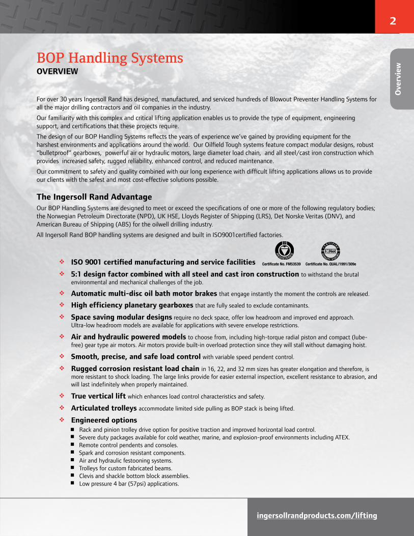
How to OrderSpecify the complete model as shown. Specify beam size, type and flange width. Note that 0 (zero) is a number, not a letter in the model part numbers.
Example: BS50LCA2P3E9M9T1-E
tons # of hoists x cap. Chain falls (# per hoist)
25 = (2 x 12.5 tons) 2 falls
30 = (2 x 15 tons) 3 falls
36 = (2 x 18 tons) 3 falls
40 = (2 x 20 tons) 4 falls
50 = (2 x 25 tons) 2 falls
or 50 = (2 x 25 tons) 4 falls
75 = (2 x 37.5 tons) 3 falls
100 = (2 x 50 tons) 4 falls
150 = (2 x 75 tons) 3 falls
200 = (2 x 100 tons) 4 falls
Series Hoist Series
Power type
Beam type
-
-BS LC2
Lift Control Options CE Package
E50 A
A = Air
H = Hydraulic
Number of chain falls
1 = 1 fall
2 = 2 falls
3 = 3 falls
4 = 4 falls
LC2 = Liftchain® LC2 Series
3
E = Flat beam
N = Tapered beam
Add the letter "R" for Rack & Pinion configuration (e.g. ER)
Available for flat beam only
9 = 9 m std.
XX = Specify length in meters
3 = 2 motor pendent (*)
0 = no control (for hyd.)
(*) Joystick type in hyd.
9M = 9 m
XX = Specify length in meters
(10 m max in hydraulic)
-E = compliance with the EC Machinery Directives (Only for air operated models)**
** CE package includes:
- Overload protection
- Emergency stop button
- Main air shut off valve
- CE declaration of conformity
BS = Blowout Preventer Handling System
SystemCapacity
Body control type
P = Pendent
F = Full Flow (hydraulic only)
Controltype
L = Low Temperature rating (TD = -20°C)
N = Clevis instead of bottom hook
QZ = Marine 812-X paint system
T1 = Spark resistant package for Zone 1 (**)
Z = Sandblast and carbozinc (primer only)
(**) Spark resistant option T1 includes:
> For the hoist:
- Stainless steel pins and fasteners 10 mm and smaller
- 20µ zinc plated fasteners 11 mm and larger
- Cast iron pendent (air only)
- Bronze coated bottom hook assembly
> For the trolley:
- Stainless steel pins and fasteners 10 mm and smaller
- 20µ zinc plated fasteners 11 mm and larger
- Solid bronze wheels
- Cast iron pendent (air only)
T19M 9EP4
Lift
chai
n®
Mod
el D
river

11
Dimensions (millimeters)Model No. A B C D E F G H J K L M N O P Q R S T W X Y Z
BHS50M 1040 1568 578 616 229 92 495 362 1422 245 251 175 286 291 102 175 219 81 65 484 - 346 699
BHS75M 1243 1648 610 673 298 129 572 438 1702 245 251 283 286 330 121 229 289 78 57 487 - 392 622
BHS100M 1346 1648 610 673 298 165 572 438 1842 245 251 321 286 330 165 229 289 78 57 487 - 622 622
Dimensions (inches)Model No. A B C D E F G H J K L M N O P Q R S T W X Y Z
BHS50M 40.94 61.75 22.75 24.25 9 3.63 19.5 14.25 56 9.63 9.88 6.88 11.25 11.44 4 6.88 8.63 3.19 2.56 19.06 - 13.63 27.5
BHS75M 48.94 64.88 24 26.5 11.75 5.06 22.5 17.25 67 9.63 9.88 11.13 11.25 13 4.75 9 11.38 3.06 2.25 19.19 - 15.44 24.5
BHS100M 53 64.88 24 26.5 11.75 6.5 22.5 17.25 72.5 9.63 9.88 12.63 11.25 13 6.5 9 11.38 3.06 2.25 19.19 - 20.63 24.5
G HS
T
Q R
K
L
M
A
F
B
C D
EZ
O
W
J
N
P
Y
Air Inlet(1" ID NPT, exceptBHS40M-8 is 3/4" ID NPT)
U1
U2
U3
*
BHS50M, BHS75M, and BHS100M series (8-wheel trolley models)
Hercu-Link™ Air BOP Handling SystemsDIMENSIONS AND DRAWINGS of Piston Motor Drive – 50 to 200 tons Lifting Capacity
Notes: Dimensions are approximate and subject to change, please contact factory for certified prints. Allow ± 2% on all dimensions.
(*) Contact Client Services for specifications.
Chain Container Dimensions for 9m (30 ft) standard lift (1) – millimeters (inches)Model No. U1 U2 U3
BHS50M 795 (31.3) 706 (27.8) 533 (21.0)
BHS75M 886 (34.9) 859 (33.8) 610 (24.0)
BHS100M 922 (36.3) 935 (36.8) 635 (25.0)
(1) Chain containers are available with many other dimensions. Please contact Client Services for details. Hercu-Link™
D
imensions

12
ingersollrandproducts.com/lifting
Liftchain® Air and Hydraulic BOP Handling SystemsDIMENSIONS AND DRAWINGS – 25 to 50 tons Lifting Capacity
Dimensions (millimeters)Model No. A B C D E F G H I J K L M
LCA Air SeriesBS25LC2A2P 1128 500 120 - 240 67 318 253 338 1415 228 85 150 BS30LC2A3P 1242 642 156 - 312 80 377 311 342 1592 228 85 200 BS36LC2A3P 1242 642 156 - 312 80 377 311 342 1592 228 85 200 BS40LC2A4P 1290 642 156 - 312 94 377 311 342 1606 228 85 200BS50LC2A4P 1290 642 156 - 312 94 377 311 342 1606 228 85 200
LCH Hydraulic SeriesBS25LC2H2P 1128 500 120 - 240 67 318 253 357 1415 228 143 150 BS30LC2H3P 1242 642 156 - 312 80 377 311 360 1592 228 143 200 BS36LC2H3P 1242 642 156 - 312 80 377 311 360 1592 228 143 200 BS40LC2H4P 1290 642 156 - 312 94 377 311 360 1606 228 143 200BS50LC2H4P 1290 642 156 - 312 94 377 311 360 1606 228 143 200
Dimensions (millimeters)Model No. N O P Q R S T U V W X Y Z
LCA Air SeriesBS25LC2A2P 203 220 58 160 200 48 68 - 58 739 - 222 -BS30LC2A3P 206 270 78 225 272 56 80 - 58 797 - 283 -BS36LC2A3P 206 270 78 225 272 56 80 - 58 797 - 283 -BS40LC2A4P 235 270 87 225 272 56 80 - 58 797 - 339 -BS50LC2A4P 235 270 87 225 272 56 80 - 58 797 - 339 -
LCH Hydraulic SeriesBS2 5LC2H2P 203 220 58 160 200 48 68 - 58 739 - 222 -BS30LC2H3P 206 270 78 225 272 56 80 - 58 797 - 283 -BS36LC2H3P 206 270 78 225 272 56 80 - 58 797 - 283 -BS40LC2H4P 235 270 87 225 272 56 80 - 58 797 - 339 -BS50LC2H4P 235 270 87 225 272 56 80 - 58 797 - 339 -
Dimensions (inches)Model No. A B C D E F G H I J K L M
LCA Air SeriesBS25LC2A2P 44.41 19.68 4.72 - 9.45 2.64 12.52 9.96 13.3 55.7 8.98 3.35 5.9 BS30LC2A3P 48.9 25.27 6.14 - 12.28 3.15 14.84 12.24 13.46 62.68 8.98 3.35 7.87 BS36LC2A3P 48.9 25.27 6.14 - 12.28 3.15 14.84 12.24 13.46 62.68 8.98 3.35 7.87 BS40LC2A4P 50.79 25.27 6.14 - 12.28 3.7 14.84 12.24 13.46 63.23 8.98 3.35 7.87BS50LC2A4P 50.79 25.27 6.14 - 12.28 3.7 14.84 12.24 13.46 63.23 8.98 3.35 7.87
LCH Hydraulic SeriesBS25LC2H2P 44.41 19.68 4.72 - 9.45 2.64 12.52 9.96 14.05 55.7 8.98 5.63 5.9 BS30LC2H3P 48.9 25.27 6.14 - 12.28 3.15 14.84 12.24 14.17 62.68 8.98 5.63 7.87 BS36LC2H3P 48.9 25.27 6.14 - 12.28 3.15 14.84 12.24 14.17 62.68 8.98 5.63 7.87BS40LC2H4P 50.79 25.27 6.14 - 12.28 3.7 14.84 12.24 14.17 63.23 8.98 5.63 7.87BS50LC2H4P 50.79 25.27 6.14 - 12.28 3.7 14.84 12.24 14.17 63.23 8.98 5.63 7.87
Dimensions (inches)Model No. N O P Q R S T U V W X Y Z
LCA Air SeriesBS25LC2A2P 7.99 8.66 2.28 6.3 7.87 1.89 2.68 - 2.28 29.09 - 8.74 -BS30LC2A3P 8.11 10.63 3.07 8.86 10.71 2.2 3.15 - 2.28 31.38 - 11.14 -BS36LC2A3P 8.11 10.63 3.07 8.86 10.71 2.2 3.15 - 2.28 31.38 - 11.14 -BS40LC2A4P 9.25 10.63 3.42 8.86 10.71 2.2 3.15 - 2.28 31.38 - 13.35 -BS50LC2A4P 9.25 10.63 3.42 8.86 10.71 2.2 3.15 - 2.28 31.38 - 13.35 -
LCH Hydraulic SeriesBS25LC2H2P 7.99 8.66 2.28 6.3 7.87 1.89 2.68 - 2.28 29.09 - 8.74 -BS30LC2H3P 8.11 10.63 3.07 8.86 10.71 2.2 3.15 - 2.28 31.38 - 11.14 -BS36LC2H3P 8.11 10.63 3.07 8.86 10.71 2.2 3.15 - 2.28 31.38 - 11.14 -BS40LC2H4P 9.25 10.63 3.42 8.86 10.71 2.2 3.15 - 2.28 31.38 - 13.35 -
BS50LC2H4P 9.25 10.63 3.42 8.86 10.71 2.2 3.15 - 2.28 31.38 - 13.35 -
Lift
chai
n®
Dim
ensi
ons

13
Liftchain® Air and Hydraulic BOP Handling SystemsDIMENSIONS AND DRAWINGS – 25 to 50 tons Lifting Capacity
BS25LC2_2 - BS30LC2_3 - BS36LC2_3 - BS40LC2_4 - BS50LC2_4 series
Chain Container Dimensions for 9m (30 ft) standard lift (1) – millimeters (inches)Model No. U1 U2 U3
BS25LC2_2P 565 (22.24) 720 (28.35) 400 (15.75)
BS30LC2_3P 565 (22.24) 720 (28.35) 400 (15.75)
BS36LC2_3P 565 (22.24) 720 (28.35) 400 (15.75)
BS40LC2_4P 565 (22.24) 720 (28.35) 550 (21.65)
BS50LC2_4P 565 (22.24) 720 (28.35) 550 (21.65)
(1) Chain containers are available with many other dimensions. Please contact Client Services for details.
V V
N
H
A
G
P
Q R
L
TS
F
Y
J
U1
U2W
C
E
B
O
U3
K
I
M
*
4 leversremote control
OST P
Air inlet 3/4" ID BSP
Notes: Dimensions are approximate and subject to change, please contact factory for certified prints. Allow ± 2% on all dimensions.
(*) Contact Client Services for specifications.
Liftchain® Dim
ensions
14
ingersollrandproducts.com/lifting
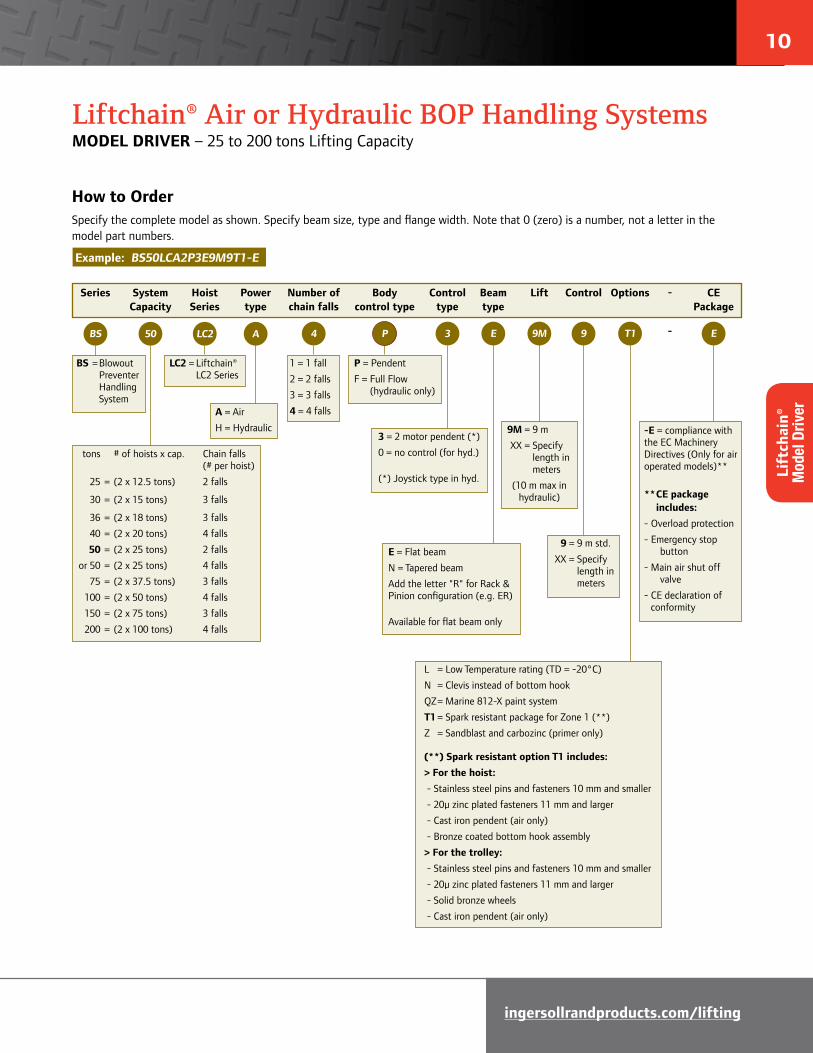
Liftchain® Air and Hydraulic BOP Handling SystemsDIMENSIONS AND DRAWINGS – 25 to 200 tons Lifting Capacity
Dimensions (millimeters)Model No. A B C D E F G H I J K L M
Liftchain® Air Series
BS50LCA2P 976 1240 370 500 240 97 492 367 342 1293 223 196 190
BS75LCA3P 1170 1552 455 642 312 132 547 472 360 1572 223 196 278
BS100LCA4P 1392 1552 455 642 312 152 547 472 360 1662 223 196 281
Liftchain® Hydraulic Series
BS50LCH2P 976 1240 370 500 240 97 446 265 357 1293 298 137 190
BS75LCH3P 1170 1552 455 642 312 132 500 372 360 1572 298 137 278
BS100LCH4P 1392 1552 455 642 312 152 500 372 360 1662 298 137 281
Dimensions (millimeters)Model No. N O P Q R S T U V W X Y Z
Liftchain® Air Series
BS50LCA2P 276 220 82 160 200 48 68 - 58 436 - 339 500
BS75LCA3P 298 270 103 225 272 56 80 - 58 494 - 384 598
BS100LCA4P 352 270 118 225 272 56 80 - 58 494 - 384 598
Liftchain® Hydraulic Series
BS50LCH2P 276 220 82 160 200 48 68 - 58 436 - 339 500
BS75LCH3P 298 270 103 225 272 56 80 - 58 494 - 384 598
BS100LCH4P 352 270 118 225 272 56 80 - 58 494 - 384 598
Dimensions (inches)Model No. A B C D E F G H I J K L M
Liftchain® Air Series
BS50LCA2P 38.42 48.82 14.57 19.68 9.45 3.82 19.37 14.45 13.46 50.9 8.78 7.72 7.48
BS75LCA3P 46.06 61.1 17.91 25.28 12.28 5.2 21.5 18.58 14.17 61.89 8.78 7.72 10.94
BS100LCA4P 54.8 61.1 17.91 25.28 12.28 5.98 21.5 18.58 14.17 65.43 8.78 7.72 11.06
Liftchain® Hydraulic Series
BS50LCH2P 38.42 48.82 14.57 19.68 9.45 3.82 17.56 10.43 14.05 50.9 11.73 5.39 7.48
BS75LCH3P 46.06 61.1 17.91 25.28 12.28 5.2 19.68 14.64 14.17 61.89 11.73 5.39 10.94
BS100LCH4P 54.8 61.1 17.91 25.28 12.28 5.98 19.68 14.64 14.17 65.43 11.73 5.39 11.06
Dimensions (inches)Model No. N O P Q R S T U V W X Y Z
Liftchain® Air Series
BS50LCA2P 10.87 8.66 3.23 6.3 7.87 1.89 2.68 - 2.28 17.16 - 13.35 19.68
BS75LCA3P 11.73 10.63 4.05 8.86 10.71 2.2 3.15 - 2.28 19.45 - 15.12 23.54
BS100LCA4P 11.73 10.63 4.65 8.86 10.71 2.2 3.15 - 2.28 19.45 - 15.12 23.54
Liftchain® Hydraulic Series
BS50LCH2P 10.87 8.66 3.23 6.3 7.87 1.89 2.68 - 2.28 17.16 - 13.35 19.68
BS75LCH3P 11.73 10.63 4.05 8.86 10.71 2.2 3.15 - 2.28 19.45 - 15.12 23.54
BS100LCH4P 11.73 10.63 4.65 8.86 10.71 2.2 3.15 - 2.28 19.45 - 15.12 23.54
Lift
chai
n®
Dim
ensi
ons

15
Liftchain® Air and Hydraulic BOP Handling SystemsDIMENSIONS AND DRAWINGS – 25 to 200 tons Lifting Capacity
BS50LC_2 - BS75LC_3 - BS100LC_4 series
U3
U1
37,5T
M
H
F
P
A
V
Y
T
S
Q R
L
J
I
G
K
U2
*
N
Z E
V
B
C D
OW
remote control4 levers
PTS O
Air Inlet
Chain Container Dimensions for 9m (30 ft) standard lift (1) – millimeters (inches)Model No. U1 U2 U3
BS50LC_2P 850 (33.46) 840 (33.07) 800 (31.50)
BS75LC_3P 955 (37.60) 1055 (41.54) 800 (31.50)
BS100LC_4P 955 (37.60) 1055 (41.54) 800 (31.50)
(1) Chain containers are available with many other dimensions. Please contact Client Services for details.
Notes:
Dimensions are approximate and subject to change, please contact factory for certified prints. Allow ± 2% on all dimensions.
(*) Contact Client Services for specifications.
Liftchain® Dim
ensions

16
ingersollrandproducts.com/lifting
Liftchain® Air and Hydraulic BOP Handling SystemsDIMENSIONS AND DRAWINGS – 25 to 200 tons Lifting Capacity
Chain Container Dimensions for 9m (30 ft) standard lift (1) – millimeters (inches)Model No. U1 U2 U3
BS150LC_3P 1200 (47.24) 1200 (47.24) 920 (36.22)
BS200LC_4P 1200 (47.24) 1200 (47.24) 920 (36.22)
(1) Chain containers are available with many other dimensions. Please contact Client Services for details.
Dimensions – millimeters (inches)Model No. A B C D E F G H I J K L M
Liftchain® Air Series
BS150LCA3P 1845 (73) 3254 (128) 906 (36) 642 (25) 312 (12) 190 (7) 714 (28) 714 (28) 360 (14) 2305 (91) 298 (12) 196 (8) 490 (19)
BS200LCA4P 1901 (75) 3254 (128) 906 (36) 642 (25) 312 (12) 212 (8) 714 (28) 714 (28) 360 (14) 2383 (94) 298 (12) 196 (8) 430 (17)
Liftchain® Hydraulic Series
BS150LCH3P 1845 (73) 3254 (128) 906 (36) 642 (25) 312 (12) 190 (7) 528 (21) 684 (27) 360 (14) 2305 (91) 298 (12) 199 (8) 490 (20)
BS200LCH4P 1901 (75) 3254 (128) 906 (36) 642 (25) 312 (12) 212 (8) 528 (21) 684 (27) 360 (14) 2383 (94) 298 (12) 199 (8) 430 (17)
Dimensions – millimeters (inches)Model No. N O P Q R S T U V W X Y Z
Liftchain® Air Series
BS150LCA3P 420 (17) 270 (11) 152 (6) 225 (9) 272 (11) 56 (2) 80 (3) - 58 (2) 790 (31) - 574 (23) 700 (28)
BS200LCA4P 490 (19) 270 (11) 180 (7) 225 (9) 272 (11) 56 (2) 80 (3) - 58 (2) 790 (31) - 606 (24) 700 (28)
Liftchain® Hydraulic Series
BS150LCH3P 420 (17) 270 (11) 152 (6) 225 (9) 272 (11) 56 (2) 80 (3) - 58 (2) 790 (31) 488 (19) 574 (23) 700 (28)
BS200LCH4P 490 (19) 270 (11) 180 (7) 225 (9) 272 (11) 56 (2) 80 (3) - 58 (2) 790 (31) 488 (19) 606 (24) 700 (28)
E E X EE
U3
H
N
F
P
Y
U1
Q I
N
A
B
V VZ
WU2
I
G
R
S
T
K
L
D
J
O
C
X
*
remote control4 levers
PTS O
Air inlet 3/4" ID BSP
BS150LC_3 - BS200LC_4 series
Notes:
Dimensions are approximate and subject to change, please contact factory for certified prints. Allow ± 2% on all dimensions.
(*) Contact Client Services for specifications.
Lift
chai
n®
Dim
ensi
ons

17
04/191996
OPTIONAL CHAIN BUCKET *
Air inlet2x 1"1/4 ID BSP
Chaincontainer
BOP Handling SystemsENGINEERED SOLUTIONS
For further information, technical support, or a quotation on one of our engineered BOP handling systems, please contact Client Services.
BHS150M and BHS200M series
ULBHS100LCA4 series (Ultra-low headroom design)
Engineered Solutions

18
ingersollrandproducts.com/lifting

Authorized Distributor:
Office and distributors in principal cities throughout the world. Contact the nearest Ingersoll Rand office for the name and address of the distributor in your country or write to: Ingersoll Rand, 20017 72nd Avenue South, Kent, WA 98032 USA.
United States Regional Sales Office
For Order Entry and Order Status: Ingersoll Rand Customer CarePhone: 866-207-6923 (Toll Free) Or 800-IR-HOISTFax: 615-874-2525
For Technical Support: Client Services20017 72nd Avenue South, Kent, WA 98032 Phone: 253-398-3900 Fax: 253-398-3475E-mail: [email protected]
International
Ingersoll Rand Canada Inc.
51 Worcester Road, Toronto, Ontario M9W 4K2Phone: 877-924-7435Order Desk: 877-924-7435Fax: 416-213-4506 (888) 422-2258 (Toll free)
Europe, Middle East and Africa Ingersoll Rand Winch & Hoist Solutions Douai Operations529, Avenue Roger Salengro, 59450 SIN LE NOBLE, FrancePhone: 33-3-27-93-08-08 Fax: 33-3-27-93-08-19E-mail: [email protected]
MéxicoIngersoll Rand S.A. de C.V.
Boulevard Centro Industrial No. 11
Industrial Puente de Vigas
54070 Tlalnepantla, Estado de México
Phone: 52 (55) 85 03 66 00 ext. 6627 & 6628
Fax: 52 (55) 55 65 30 72
E-mail: mexicot&[email protected]
BrazilAlameda Caiapós 311
Tamboré - Barueri - Sáo Paulo - Brazil 06460-110
Phone: 55-11-2109 . 8950
Fax: 55-11-2109 . 8998
Australia Ingersoll Rand Ltd.
Landmark Corporate Centre45-47 Ventura Place
Dandenong South, Victoria 3175, Australia
Phone: 61-3-8787-4300
Fax: 61-3-8787-5510
Ingersoll Rand IndiaUnit #31, 3rd Floor, 2nd Level‘Kalpataru Square’, Andheri-Kurla RoadAndheri (East), Mumbai 400 059 IndiaPhone: 91-22-61540500Fax: 91-22-28315302 and 91-22-28315703
Ingersoll Rand SEA Pte. Ltd.42 Benoi Road, Jurong, Singapore 629903Phone: 65-6861-1555 Fax: 65-6862-1373
China Ingersoll Rand Co.11F, Tower B, City Center of Shanghai,100 Zun Yi Road, Shanghai, 200051, P.R.C.Phone: 86-21-2208 1580Fax: 86-21-6237 1993
Ingersoll Rand Industrial Technologies provides products, services and solutions that enhance our customers’ energy efficiency, productivity and operations. Our diverse and innovative products range from complete compressed air systems, tools and pumps to material and fluid handling systems. We also enhance productivity through solutions created by Club Car®, the global leader in golf and utility vehicles for businesses and individuals.
© 2012 Ingersoll Rand Company MHD55341 / 03132012