Embed Size (px)
Citation preview
Boot ROM Configuration Mode Users Manual
HP 9000 Products
rli~ HEWLETT . .:~ PACKARD
HP Part No. 98574·90600 Printed in USA January, 1990
E0190
© Copyright 1983, 1984,1985, 1986, 1987, 1988, 1989, 1990 Hewlett-Packard Co. © Copyright 1979 by Regents of the Univ. of Colorado, A Body Corporate. © Copyright 1979, 1980, 1983, 1985-1988 by The Regents of the Univ. of California. © Copyright 1980, 1984, 1986 by AT&T Technologies, Inc. © Copyright 1986, 1987, 1988 by Sun Microsystems, Inc. © Copyright 1986 by Digital Equipment Corp. © Copyright 1985, 1986 by Massachusetts Institute of Technology. All Rights Reserved
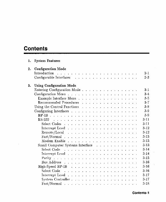
Contents
1. System Features
2. Configuration Mode Introduction . . . Configurable Interfaces
3. Using Configuration Mode Entering Configuration Mode Configuration Menu . . . .
Example Interface Menu . Recommended Procedures
U sing the Control Functions Configuring Interfaces .
HP-IB .... . RS-232 ... .
Select Codes . Interrupt Level Remote / Local Fast/Normal . Modem Enable
Small Computer Systems Interface Select Code Interrupt Level Parity .... Bus Address .
High-Speed HP-IB Select Code Interrupt Level . System Controller . Fast/Normal . . .
. ~
2-1 2-3
3-1 3-4 3-5 3-7 3-8 3-9 3-9
3-11 3-11 3-12 3-12 3-13 3-13 3-13 3-14 3-14 3-15 3-16 3-16 3-16 3-17 3-17 3-18
Contents-1
98625B Mode. . . Local Area Network.
Select Code Interrupt Level . .
HP Parallel Interface Select Code Interrupt Level . .
Contents-2
3-18 3-19 3-19 3-19 3-20 3-20 3-21
Figures
2-1. Power-Up and Self-Test Display . 3-1. Power-Up and Self-Test Display . 3-2. Configuration Mode Display ..
Tables
3-1. Configuration Mode Entry Error Messages . 3-2. Configuration Mode Exit Error Messages.
2-2 3-2 3-3
3-4 3-9
Using Configuration Mode Contents-3

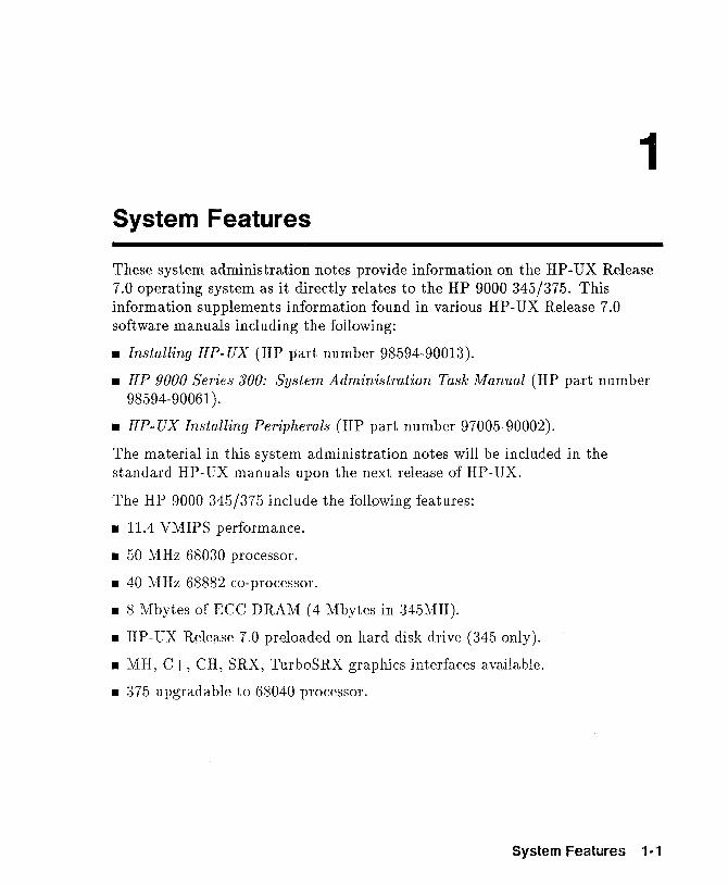
1 System Features
These system administration notes provide information on the HP-UX Release 7.0 operating system as it directly relates to the HP 9000 345/375. This information supplements information found in various HP-UX Release 7.0 software manuals including the following:
• Installing HP- UX (HP part number 98594-90013).
• HP 9000 Series 300: System Administration Task Manual (HP part number 98594-90061 ).
• HP- UX Installing Peripherals (HP part number 97005-90002).
The material in this system administration notes will be included in the standard HP-UX manuals upon the next release of HP-UX.
The HP 9000 345/375 include the following features:
• 11.4 VMIPS performance.
• 50 MHz 68030 processor.
• 40 MHz 68882 co-processor.
• 8 Mbytes of ECC DRAM (4 Mbytes in 345MH).
• HP- UX Release 7.0 preloaded on hard disk drive (345 only).
• MH, C+, CH, SRX, TurboSRX graphics interfaces available.
• 375 upgradable to 68040 processor.
System Features 1-1

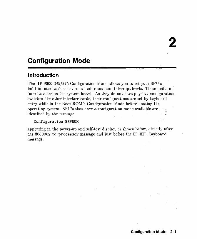
2 Configuration Mode
Introduction
The HP 9000 345/375 Configuration Mode allows you to set your SPU's built-in interface's select codes, addresses and interrupt levels. These built-i~ interfaces are on the system board. As they do not have physical configuration switches like other interface cards, their configurations are set })y keyboard entry while in the Boot ROM's Configuration Mode before booting the operating system. SPU's that have a configuration mode available are identified by the message:
Configuration EEPROM
appearing in the power-up and self-test display, as shown below, directly after the MC68882 Co-processor message and just before the HP-HIL . Keyboard message.
Configuration Mode 2-1
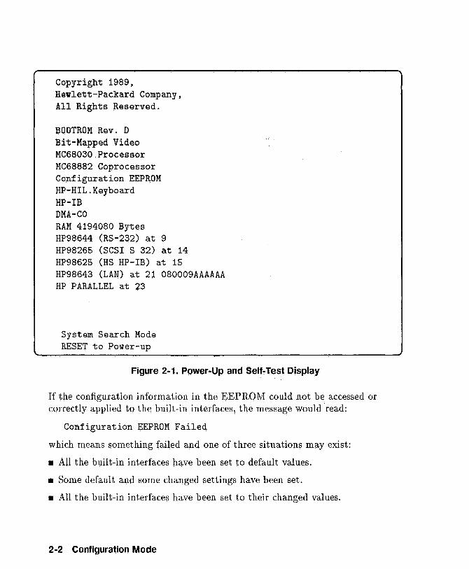
Copyright 1989, Hewlett-Packard Company, All Rights Reserved.
BOOTROM Rev. D Bit-Mapped Video MC68030 Processor MC68882 Coprocessor Co~figuration EEPROM HP-HIL.Keyboard HP-IB DMA-CO RAM 4194080 Bytes HP98644 (RS-232) at 9 HP98265 (SCSI S 32) at 14 HP98625 (HS HP-IB) at 15 HP98643 (LAN) at 21 080009AAAAAA HP PARALLEL at 23
System Search Mode RESET to Power-up
Figure 2-1. Power-Up and Self-Test Display
If the configuration information in the EEPROM could not be accessed or correctly applied to the built-in interfaces, the message would'read:
Configuration EEPROM Failed
which means something failed and one of three situations may exist:
• All the built-in interfaces have been set to default values.
• Some default and some changed settings have been set.
• All the built-in interfaces have been set to their changed values.
2-2 Configuration Mode
It is possible that all interfaces have been configured properly, but you will still receive the error message. After you have confirmed that all interfaces have been configured properly, continue with the system boot up process.
Configurable Interfaces You should enter configuration mode and find out what each built-in interface configuration values are set. Interfaces that have their configurations controlled by configuration mode are:
• HP-IB.
• RS-232.
• Small Computer Systems Interface.
• High-Speed HP-IB.
• Local Area Network.
• HP Parallel.
After you have set your built-in interface select codes and addresses, these values are stored in Electrically Erasable Programmable Read-Only Memory, or EEPROMS. If you turn your SPU off, then back on, your configuration values are still set. You may change them to suit your applications whenever you want by resetting your SPU and entering the Configuration Mode.
In the next chapter, using the menus and user responses are shown in order. This is done to show you what the menus look like. Menu items may be selected in any order.
N ate that menu changes will not be shown in the self-test results on the left side of the screen until the changes effected by the menus are saved and the self-test re-run.
Configuration Mode 2-3

3 Using Configuration Mode
Entering Configuration Mode When you see the following power-up and self-test display, type © (Return) to enter the Configuration Mode.
Using Configuration Mode 3-1
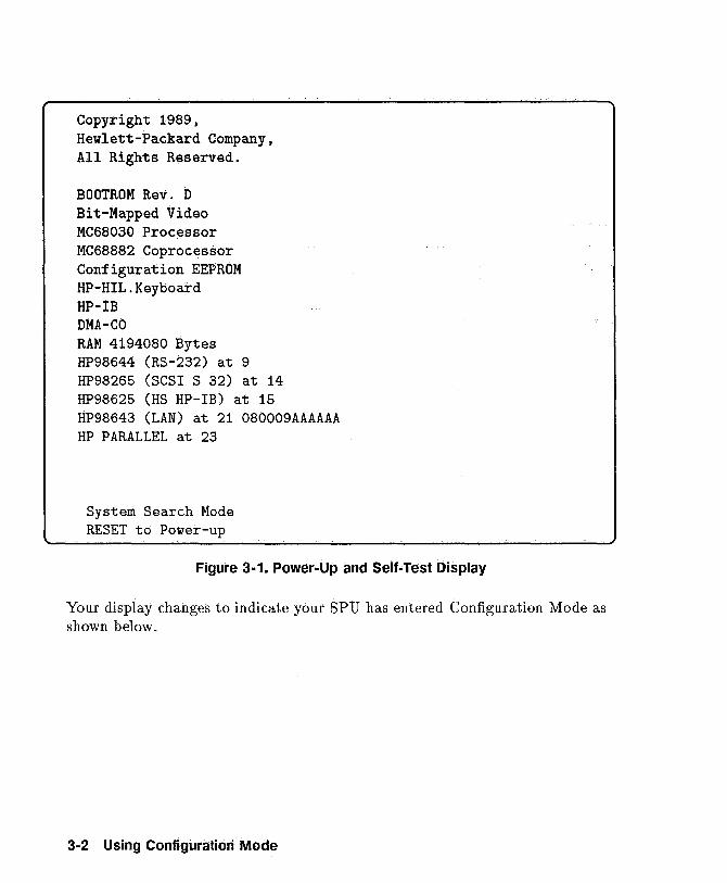
Copyright 1989, Hewlett-Packard Company, All Rights Reserved.
BOOTROM Rev. D Bit-Mapped Video MC68030 Processor MC68882 Coprocessor Configuration EEPROM HP-HIL.Keyboard HP-IB DMA-CO RAM 4194080 Bytes HP98644 (RS-232) at 9 HP98265 (SCSI S 32) at 14 HP98625 (HS HP-IB) at 15 HP98643 (LAN) at 21 080009AAAAAA HP PARALLEL at 23
System Search Mode RESET to Power-up
Figure 3-1. Power-Up and Self-Test Display
Your display changes to indicate your SPU has entered Configuration Mode as shown below.
3;.2 Using Configuration Mode
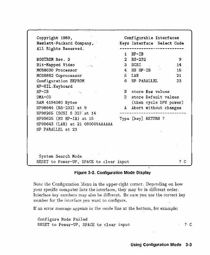
Copyright 1989, Hewlett-Packard Company, All Rights Reserved.
BOOTROM Rev. D Bit-Mapped Video MC68030 Processor MC68882 Coprocessor Configuration EEPROM HP-HIL.Keyboard HP-IB DMA-CO RAM 4194080 Bytes HP98644 (RS-232) at 9 HP98265 (SCSI S 32)' at 14 HP98625 (HS HP-IB) at 15 HP98643 (LAN) at 21 080009AAAAAA HP PARALLEL at 23
System Search Mode
Configurable Interfaces Keys Interface Select Code
1 HP-IB 2 RS-232 3 SCSI 4 HS HP-IB
9 14 15
5 LAN 21 6 HP PARALLEL 23
N store New values D store Default values
(then cycle SPU power) A Abort without changes
Type [key] RETURN ?
RESET to Power-UP, SPACE to clear input ? C
Figure 3-2. Configuration Mode Display
Note the Configuration Menu in the upper-right corner. Depending on how your specific computer lists the interfaces, they may be in different order. Interface key numbers may also be different. Be sure you use the correct key number for the interface you want to configure.
If an error message appears in the mode line at the bottom, for example:
Configure Mode Failed RESET to Power-UP, SPACE to clear input ? C
Using Configuration Mode 3-3
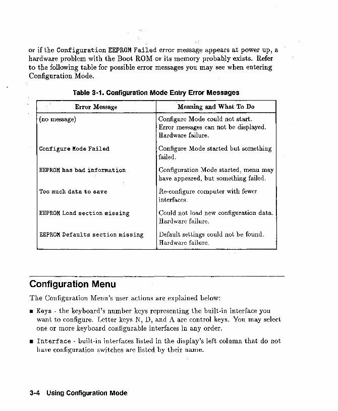
or if the Configuration EEPROM Failed error message appears at power up, a hardware problem with the Boot ROM or its memory probably exists. Refer to the following table for possible error messages you may see when entering Configuration Mode.
Table 3-1. Configuration Mode Entry Error Messages
Error Message Meaning and What To Do
(no message) Configure Mode could not start. Error messages can not be displayed. Hardware failure.
Configure Mode Failed Configure Mode started but something failed.
EEPROM has bad information Configuration Mode started, menu may have appeared, but something failed.
Too much data to save Re-configure computer with fewer interfaces.
EEPROM Load section missing Could not load new configuration data. Hardware failure.
EEPROM Defaults section missing Default settings could not be found. Hardware failure.
Configuration Menu The Configuration Menu's user actions are explained below:
• Keys - the keyboard's number keys representing the built-in interface you want to configure. Letter keys N, D, and A are control keys. You may select one or more keyboard configurable interfaces in any order .
• Interface - built-in interfaces listed in the display's left column that do not have configuration switches are listed by their name.
3-4 Using Configuration Mode
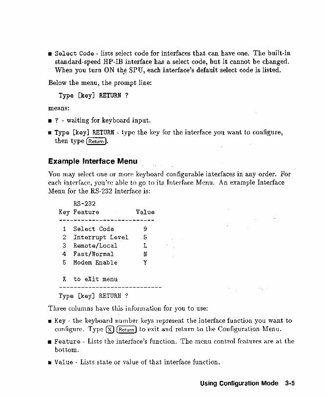
• Select Code - lists select code for interfaces that can have one. The built-in standard-speed HP-IB interface has a select code, but it cannot be changed. When you turn ON th~ SPU, each interface's default select code is listed.
Below the menu, the prompt line:
Type [key] RETURN ?
means:
• ? - waiting for keyboard input.
• Type [key] RETURN - type the key for the interface you want to configure, then type (Return ).
Example Interface Menu
You may select one or more keyboard configurable interfaces in any order. For each interface, you're able to go to its Interface Menu. An example Interface Menu for the RS-232 Interface is:
RS-232 Key Feature Value --------------------------
1 Select Code 9 2 Interrupt Level 5 3 Remote/Local L 4 Fast/Normal N 5 Modem Enable y
X to eXit menu
Type [key] RETURN ?
Three columns have this information for you to use:
• Key - the keyboard number keys represent the interface function you want to configure. Type ® (Return) to 'exit and return to the Configuration Menu.
• Feature - Lists the interface's function. The menu control features are at the bottom.
• Value - Lists state or value of that interface function.
Using Configuration Mode 3-5
Note that all Interface Menus are not the same. Each has its own functions available for configuration.
Below the menu, the prompt line:
Type [key] RETURN ?
means:
• ? - waiting for keyboard input.
• Type [key] RETURN - type the key for the interface you want to configure, then type (Return 1.
• You may just type (Return) exit the Interface Menu and return to the Configuration Menu.
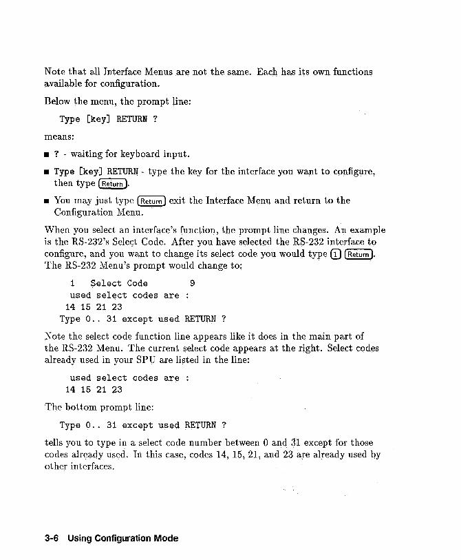
When you select an interface's function, the prompt line changes. An example is the RS-232's Select Code. After you have selected the RS-232 interface to configure, and you want to change its select code you would type CD (Return ).
The RS-232 Menu's prompt would change to:
1 Select Code used select codes are
14 15 21 23
9
Type 0 .. 31 except used RETURN?
Note the select code function line appears like it does in the main part of the RS-232 Menu. The current select code appears at the right. Select codes already used in your SPU are listed in the line:
used select codes are : 14 15 21 23
The bottom prompt line:
Type 0 .. 31 except ~sed RETURN?
tells you to type in a select code number between 0 and 31 except for those codes already used. In this case, codes 14, 15, 21, and 23 are already used by other interfaces.
3·6 Using Configuration Mode
Recommended Procedures
A good way for you to use the Configuration Mode is explained below:
1. Find out and write down what interface configurations your application and peri pherals need for:
• Select Codes.
• Interrupt Levels.
• Addresses.
• Fast or Normal Speed.
• DMA bus width.
• System Controller.
• Remote or Local.
• Modem Enable.
2. Turn ON your SPU and get it into Configuration Mode.
3. Determine what interface you will configure first.
4. Go to that section in this chapter for instructions.
5. Read the instructions and change that interface's configuration.
6. Return to the main Configuration Menu.
7. Go to the following section titled 'Using the Control Functions.'
8. Do those steps and exit Configuration Mode.
using Configuration Mode 3 .. 7
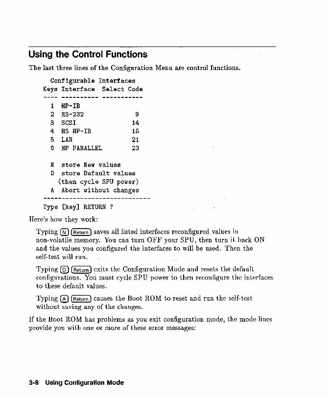
Using the Control Functions The last three lines of the Configuration Menu are control functions.
Configurable Interfaces Keys Interface Select Code
1 HP-IB 2 RS-232 9 3 SCSI 14 4 HS HP-IB 15 5 LAN 21 6 HP PARALLEL 23
N store New values D store Default values
(then cycle SPU power) A Abort without changes
Type [key] RETURN ?
Here's how they work:
Typing @ (Return) saves all listed interfaces reconfigured values in non-volatile memory. You can turn OFF your SPU, then turn it back ON and the values you configured the interfaces to will be used. Then the self-test will run.
Typing ® (Return) exits the Configuration Mode and resets the default configurations. You must cycle SPU power to then reconfigure the interfaces to these default values.
Typing 0 (Return) causes the Boot RO M to reset and run the self-test without saving any of the changes.
If the Boot ROM has problems as you exit configuration mode, the mode lines provide you with one or more of these error messages:
3-8 Using Configuration Mode
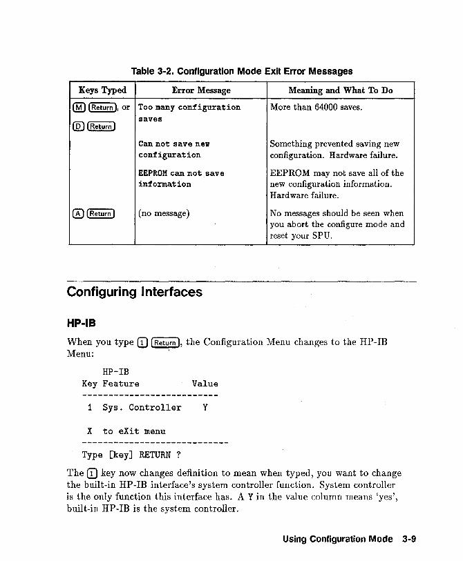
Table 3·2. Configuration Mode Exit Error Messages
Keys Typed Error Message Meaning and What To Do
® [Return ), or Too many configuration More than 64000 saves.
@) [Return) saves
Can not save new Something prevented saving new configuration configuration. Hardware failure.
EEPROM can not save EEPROM may not save all of the information new configuration information.
Hardware failure.
® [Return) (no message) No messages should be seen when you abort the configure mode and reset your SPU.
Configuring Interfaces
Hp·IB
When you type CD [Return ), the Configuration Menu changes to the HP-IB Menu: '
HP-IB Key Feature Value
1 Sys. Controller Y
X to eXit menu
Type [key] RETURN ?
The CD key now changes definition to mean when typed, you want to change the built-in HP-IB interface's system controller function. System controller is the only function this interface has. A Y in the value column means 'yes', built-in HP-IB is the system controller.
Using Configuration Mode 3-9
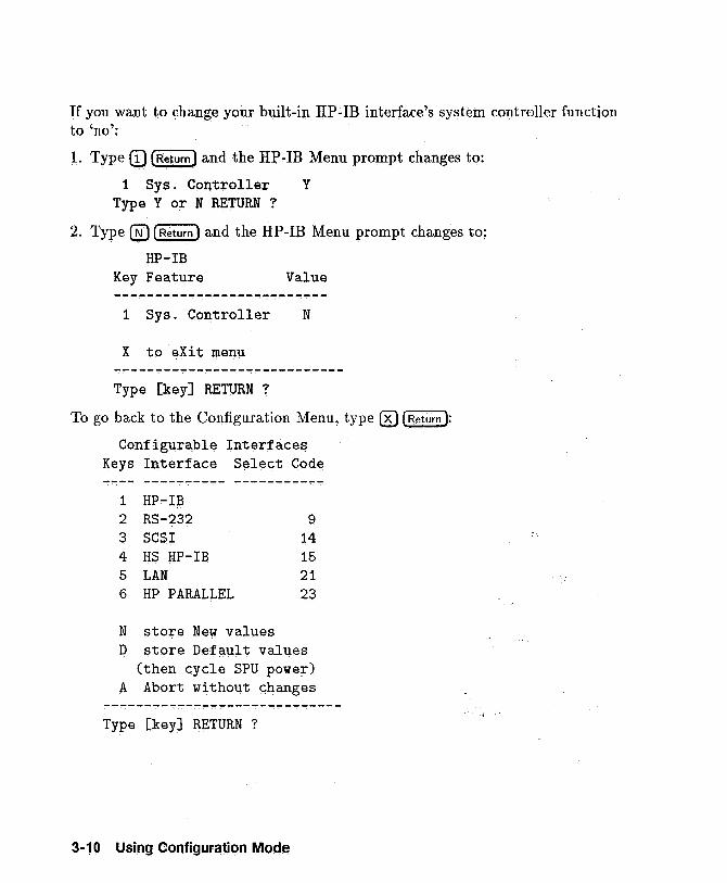
If you want to change your built-in HP-IB interface's system controller function to 'no':
1. Type (!) [Return) and the HP-IB Menu prompt changes to:
1 SY8. Controller Y Type Y or N RETURN ?
2. Type ® (Return) and the HP-IB Menu prompt changes to;
HP-IB Key Feature Value
1 Sys. Controller N
X to eXit menu
Type [key] RETURN ?
To go back to the Configuration Menu, type ® [Return ):
Configurable Interfaces Keys Interface Select Code
1 HP-IB 2 RS-232 9 3 SCSI 14 4 HS HP-IB 15 5 LAN 21 6 HP PARALLEL 23
N store New values D store Default values
(then cycle SPU power) A Abort without changes
Type [key] RETURN ?
3·10 Using Configuration Mode
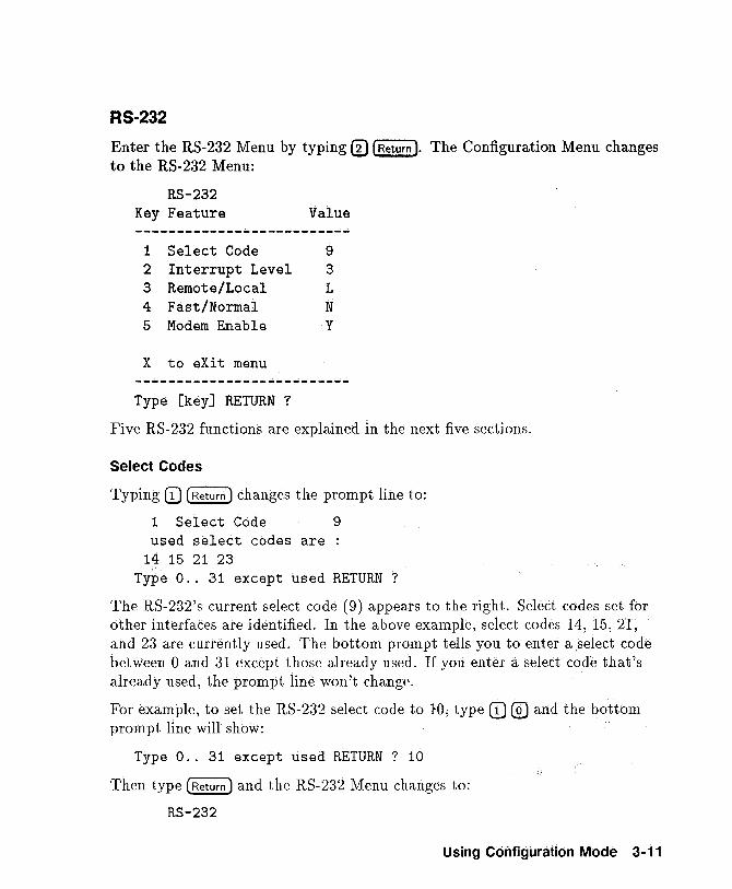
RS-232
Enter the RS-232 Menu by typing ® (Return ). The Configuration Menu changes to the RS-232 Menu:
RS-232 Key Feature Value --------------------------
1 Select Code 9 2 Interrupt Level 3 3 Remote/Local L 4 Fast/Normal N 5 Modem Enable Y
X to eXit menu
Type [key] RETURN ?
Five RS-232 functions are explained in the next five sections.
Select Codes
Typing CD (Return) changes the prompt line to:
1 Select Code 9 used select codes are :
14 15 21 23 Type 0 .. 31 except used RETURN?
The RS-232's current select code (9) appears to the right. Select codes set for other interfaces are identified. In the above example, select codes 14, 15, 21, and 23 are currently used. The bottom prompt tells you to enter a select code between 0 and 31 except those already used.. If you enter a select code that's already used, the prompt line won't change. .
For example, to set the RS-232 select code to 10, type CD @) and the bottom prompt line will show:
Type 0 .. 31 except used RETURN? 10
Then type (Return) and the RS-232 Menu changes to:
RS-232
Using Configuration Mode 3-11
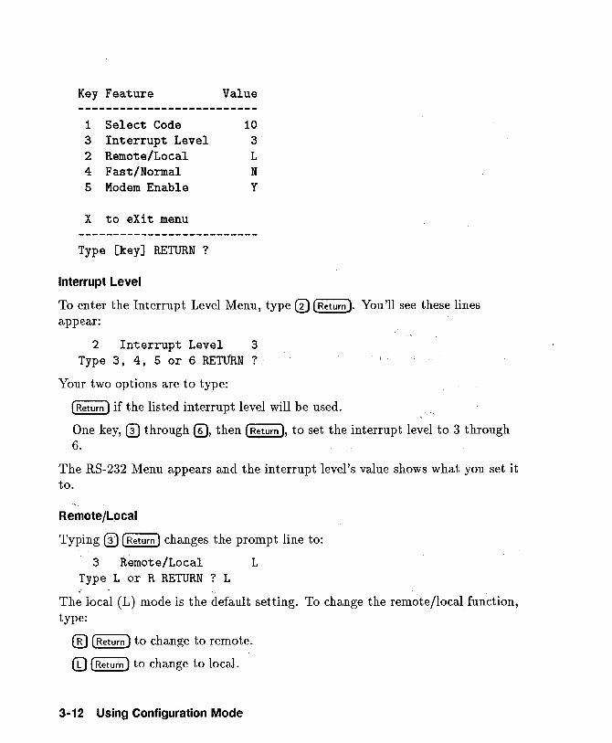
Key Feature Value --------------------------
1 Select Code 10 3 Interrupt Level 3 2 Remote/Local L 4 Fast/Normal N 5 Modem Enable Y
X to eXit menu
Type [key] RETURN ?
Interrupt Level
To enter the Interrupt Level Menu, type (1) (Return ). You'll see these lines appear:
2 Interrupt Level 3 Type 3, 4, 5 or6 RETURN?
Your two options are to type:
(Return) if the listed interrupt level will be used.
One key, 0 through 0, then (Return ), to set the interrupt level to 3 through 6.
The RS-232 Menu appears and the interrupt level's value shows what you set it to.
Remote/Local
Typing 0 (Return) changes the prompt line to:
3 Remote/Local L Type L or R RETURN ? L
The local (L) mode is the default setting. To change the remote/local function, type:
® (Return) to change to remote.
CD (Return) to change to local.
3-12 Using Configuration Mode
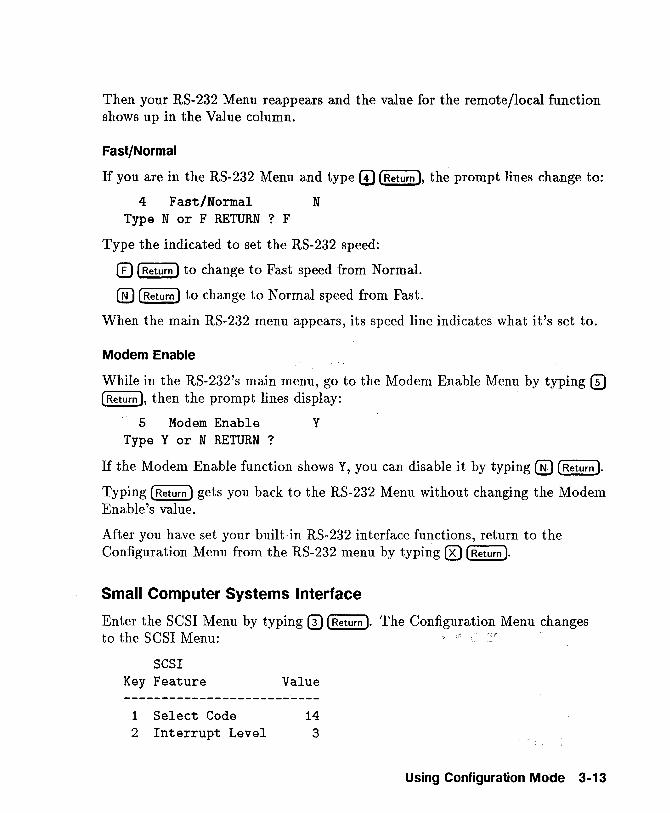
Then your RS-232 Menu reappears and the value for the remote/local function shows up in the Value column.
Fast/Normal
If you are in the RS-232 Menu and type CD (Return ), the prompt lines change to:
4 Fast/Normal N Type N or F RETURN ? F
Type the indicated to set the RS-232 speed:
CD (Return) to change to Fast speed from Normal.
@ (Return) to change to Normal speed from Fast.
When the main RS-232 menu appears, its speed line indicates what it's set to.
Modem Enable
While in the RS-232's main menu, go to the Modem Enable Menu by typing CD (Return ), then the prompt lines display:
5 Modem Enable Y Type Y or N RETURN ?
If the Modem Enable function shows Y, you can disable it by typing ® ~. Typing (Return) gets you back to the RS-232 Menu without changing the Modem Enable's value.
After you have set your built-in RS-232 interface functions, return to the Configuration Menu from the RS-232 menu by typing ® (Return ).
Small Computer Systems Interface
Enter the SCSI Menu by typing 0 (Return ). The Configuration Menu changes to the SCSI Menu:
SCSI Key Feature Value
1 Select Code 14 2 Interrupt Level 3
Using Configuration Mode 3-13
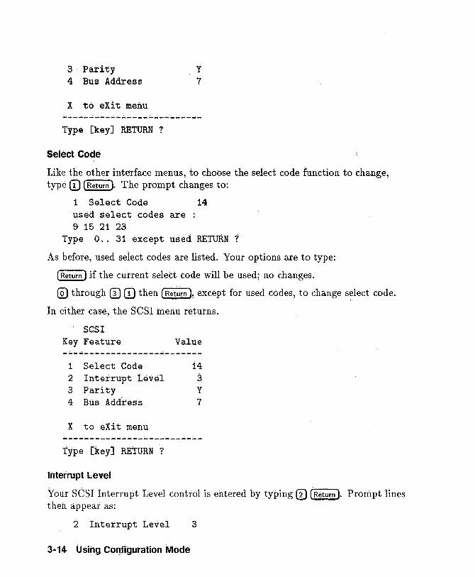
3 Parity 4 Bus Address
X to eXit menu
Type [key] RETURN ?
Select Code
y
7
Like the other interface menus, to choose the select code function to change, type CD (Return ). The prompt changes to:
1 Select Code used select codes are : 9 15 21 23
14
Type 0 .. 31 except used RETURN?
As before, used select codes are listed. Your options are to type:
(Return) if the current select code will be used; no changes.
® through 0 CD then ("Re'iUffi), except for used codes, to change select code.
In either case, the SCSI menu returns.
SCSI Key Feature
1 Select Code
Value
14 2 Interrupt Level 3 3 Parity Y 4 Bus Address 7
X to eXit menu
Type [key] RETURN ?
Interrupt Level
Your SCSI Interrupt Level control is entered by typing CD [Return ). Prompt lines then appear as:
2 Interrupt Level 3
3 .. 14 Using COQliguration Mode
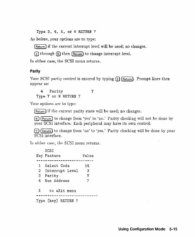
Type 3, 4, 5, or 6 RETURN?
As before, your options are to type:
(Return I if the current interrupt level will be used; no changes.
o through ® then (Return I to change interrupt level.
In either case, the SCSI menu returns.
Parity
Your SCSI parity control is entered by typing 0 (Return I. Prompt lines then appear as:
4 Parity Y Type Y or N RETURN ?
Your options are to type:
(Return I if the current parity state will be used; no changes.
@) (Return I to change from 'yes' to 'no.' Parity checking will not be done by your SCSI interface. Each peripheral may have its own control.
o (Return I to change from 'no' to 'yes.' Parity checking will be done by your SCSI interface.
In either case, the SCSI menu returns.
SCSI Key Feature Value
1 Select Code 14 2 Interrupt Level 3 3 Parity Y 4 Bus Address 7
X to eXit menu
Type [key] RETURN?
Using Configuration Mode 3-15
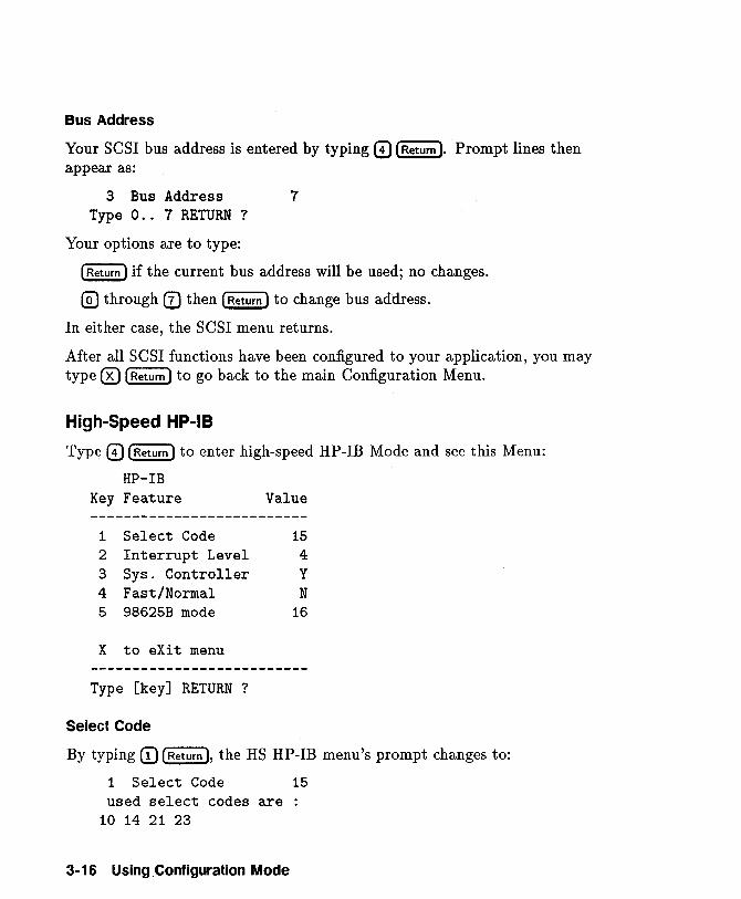
Bus Address
Your SCSI bus address is entered by typing 0 [Return ). Prompt lines then appear as:
3 Bus Address 7 Type 0 .. 7 RETURN?
Your options are to type:
[Return) if the current bus address will be used; no changes.
@) through (1) then [Return) to change bus address.
In either case, the SCSI menu returns.
After all SCSI functions have been configured to your application, you may type ® [Return) to go back to the main Configuration Menu.
High-Speed HP-IB
Type 0 [Return) to enter high-speed HP-IB Mode and see this Menu:
HP-IB Key Feature Value --------------------------
1 Select Code 15 2 Interrupt Level 4 3 Sys. Controller Y 4 Fast/Normal N 5 98625B mode 16
X to eXit menu
Type [key] RETURN ?
Select Code
By typing (!) [Return ), the HS HP-IB menu's prompt changes to:
1 Select Code 15 used select codes are :
10 14 21 23
3-16 Using. Configuration Mode
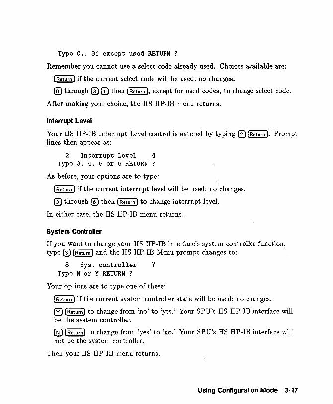
Type 0 .. 31 except used RETURN?
Remember you cannot use a select code already used. Choices available are:
CReiUffi) if the current select code will be used; no changes.
@) through 0 CD then (Return ), except for used codes, to change select code.
After making your choice, the HS HP -IB menu returns.
Interrupt Level
Your HS HP-IB Interrupt Level control is entered by typing [) [Return ). Prompt lines then appear as:
2 Interrupt Level 4 Type 3, 4, 5 or 6 RETURN?
As before,your options are to type:
CReiUffi) if the current interrupt level will be used; no changes.
o through 0 then [Return) to change interrupt level.
In either case, the HS HP-IB menu returns.
System Controller
If you want to change your HS HP-IB interface's system controller function, type 0 [Return) and the HS HP-IB Menu prompt changes to:
3 Sys. controller Y Type N or Y RETURN ?
Your options are to type one of these:
(Return) if the current system controller state will be used; no changes.
o (Return) to change from 'no' to 'yes.' Your SPU's HS HP-IB interface will be the system controller.
@ (Return) to change from 'yes' to 'no.' Your SPU's HS HP-IB interface will not be the system controller.
Then your HS HP-IB menu returns.
Using Configuration Mode 3·17
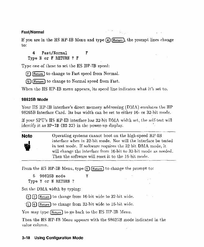
Fast/Normal
If you are in the HS HP-IB Menu and type 0 [Return ), the prompt lines change to:
4 Fast/Normal F Type N or F RETURN ? F
Type one of these to set the HS HP-IB speed:
CD [Return) to change to Fast speed from Normal.
@ [Return) to change to Normal speed from Fast.
When the HS HP-IB menu appears, its speed line indicates what it's set to.
986258 Mode
Your HS HP-IB interface's direct memory addressing (DMA) emulates the HP 98265B Interface Card. Its bus width can be set to either 16- or 32-bit mode.
If your SPU's HS HP-IB interface has 32-bit DMA width set, the self test will identify it as HP- IB (HS 32) in the power-up display. -;
Note
" Operating systems cannot boot on the high-speed HP-IB interface when in 32-bit mode. Nor will the interface be tested in test mode. If software requires the 32-bit DMA mode, it will change the interface from 16-bit to 32-bit mode as needed. Then the-software will reset it to the 16-bit mode.
From the HS HP-IB Menu, type CD (Return) to change the prompt to:
5 98625B mode Type Y or N RETURN ?
Set the DMA width by typing:
Y
0(1) [Return) to change from 16-bit wide to 32-bit wide.
, CD 0 [Return) to change from 32-bi t wi de to 16-bi t wi de.
You may type [Return) to go back to the HS HP-IB Menu.
Then the HS HP-IB Menu appears with the 98625B mode indicated in the value column.
3-18 Using Configuration Mode
After your HS HP-IB Menu shows the configuration you need, type 0 (return)
to get back to the main Configuration Menu.
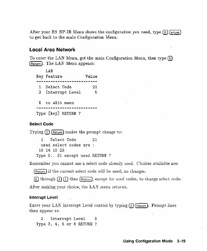
Local Area Network
To enter the LAN Menu, get the main Configuration Menu, then type CD (Rettiffi). The LAN Menu appears:
LAN Key Feature Value
1 Select Code 21 2 Interrupt Level 5
X to eXit menu
Type [key] RETURN ?
Select Code
Typing CD (Return) makes the prompt change to:
1 Select Code used select codes are
10 14 15 23
21
Type 0 .. 31 except used RETURN?
Remember you cannot use a select code already used. Choices available are:
(Return) if the current select code will be used; no changes.
@) through 0 CD then (Return ), except for used codes, to change select code.
After making your choice, the LAN menu returns.
Interrupt Level
Enter your LAN Interrupt Level control by typing 0 (Return ). Prompt lines then appear as:
2 Interrupt Level 5 Type 3, 4, 5 or 6 RETURN?
Using Configuration Mode 3-19
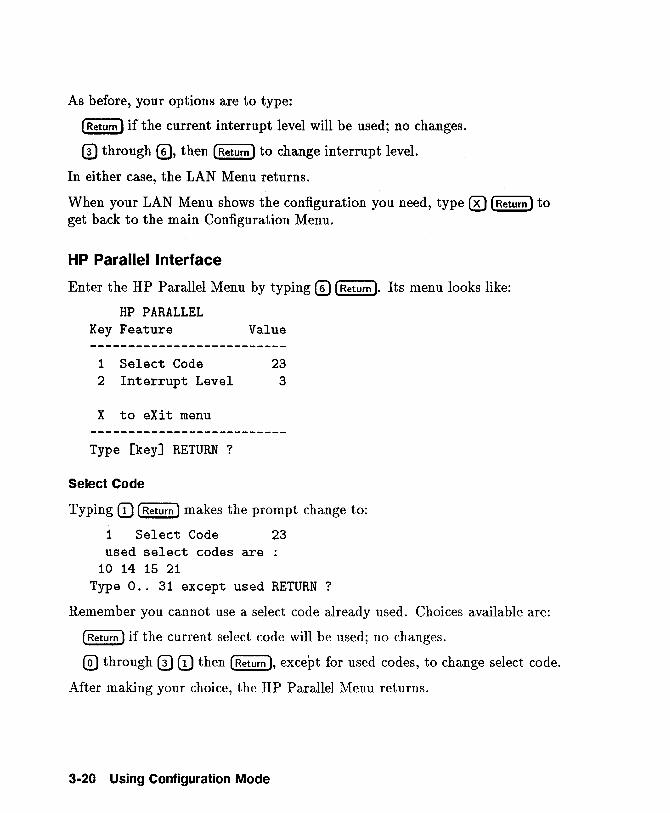
As before, your options are to type:
(Return) if the current interrupt level will be used; no changes.
o through 0, then (Return) to change interrupt level.
In either case, the LAN Menu returns.
When your LAN Menu shows the configuration you need, type 0 (Return) to get back to the main Configuration Menu.
HP Parallel Interface
Enter the HP Parallel Menu by typing 0 [Return ). Its menu looks like:
HP PARALLEL Key Feature Value
1 Select Code 23 2 Interrupt Level 3
X to eXit menu
Type [key] RETURN ?
Select Code
Typing (D [Return) makes the prompt change to:
1 Select Code 23 used select codes are :
10 14 15 21 Type 0 .. 31 except used RETURN?
Remember you cannot use a select code already used. Choices available are:
(Return) if the current select code will be used; no changes.
@) through 0 (D then (Return ), except for used codes, to change select code.
After making your choice, the HP Parallel Menu returns.
3-20 Using Configuration Mode
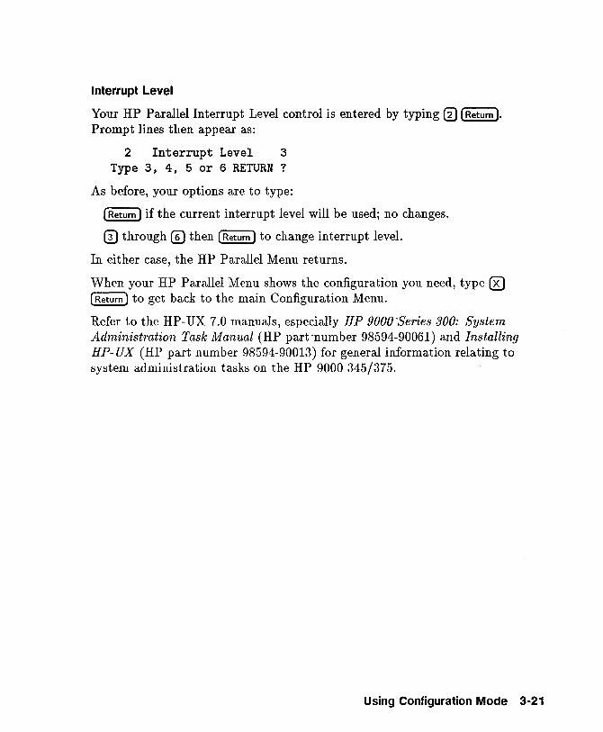
Interrupt Level
Your HP Parallel Interrupt Level control is entered by typing 0 [Return ).
Prompt lines then appear as:
2 Interrupt Level 3 Type 3, 4, 5 or 6 RETURN?
As before, your options are to type:
[Return) if the current interrupt level will be used; no changes.
o through ® then [Return) to change interrupt level.
In either case, the HP Parallel Menu returns.
When your HP Parallel Menu shows the configuration you need, type 0 [Return) to get back to the main Configuration Menu.
Refer to the HP-UX 7.0 manuals, especially HP 9000 "Series 300: System Administration Task Manual (HP part 'number 98594-90061) and Installing HP- UX (HP part number 98594-90013) for general information relating to system administration tasks on the HP 9000 345/375.
Using Configuration Mode 3-21

READER COMMENT SHEET
GSY System Learning Products
SAN for the HP 9000/345/375 Manual Part Number 98574-90600 January 1990
A reader comment sheet helps us to improve the readability and accuracy of the document. It is also a vehicle for recommending enhancements to the product or manual. Please use it to suggest improvements.
Editorial suggestions (please Include page numbers):
Recommended Improvements (attach additional Information, If needed):
Name: ________________________________ ___ Date: ____________ _
Job ntle: _________________________________ Phone: ____________ __
Company: ________________________________________________________ _
Address: ________________________________________________________ __
D Check here if you would like a reply.
Hewlett-Packard has the right to use submitted suggestions without obligation, with all such ideas becoming property of Hewlett-Packard.
'a6pa wonoq adel pue PIO=,
NO POSTAGE NECESSARY
IF MAILED IN THE
UNITED STATES
BUSINESS REPLY MAIL FIRST CLASS PERMIT NO. 1070, CUPERTINO, CA 95014 ...... -
- POSTAGE WILL BE PAID BY ADDRESSEE-
USO System Learning Products Manager General Systems Division, Mailstop 48S0 Hewlett-Packard Company 19483 Pruneridge Avenue Cupertino, California 95014-9786
II II III II I II 111111 II 1111111111111111111111111111 II II


HP Part Number 98574-90600
Printed in U.S.A. E0190
FliOW HEWLETT ~~ PACKARD
98574-90600
~P'I HEWLETT .:a PACKARD
Configuration Mode Update
Customer Note
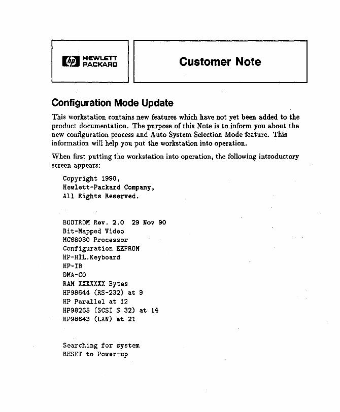
This workstation contains new features which have not yet been added to the product documentation. The purpose of this Note is to inform you about the new configuration process and Auto System Selection Mode feature. This information will help you put the workstation into operation.
When first putting the workstation into operation, the following introductory screen appears:
Copyright 1990, Hewlett-Packard Company, All Rights Reserved.
BOOTROM Rev. 2.0 29 Nov 90 Bit-Mapped Video MC68030 Processor Configuration EEPROM HP-HIL.Keyboard HP-IB DMA-CO RAM XXXXXXX Bytes HP98644 (RS-232) at 9 HP Parallel at 12 HP98265 (SCSI S 32) at 14 HP98643 (LAN) at 21
Searching for system RESET to Power-up
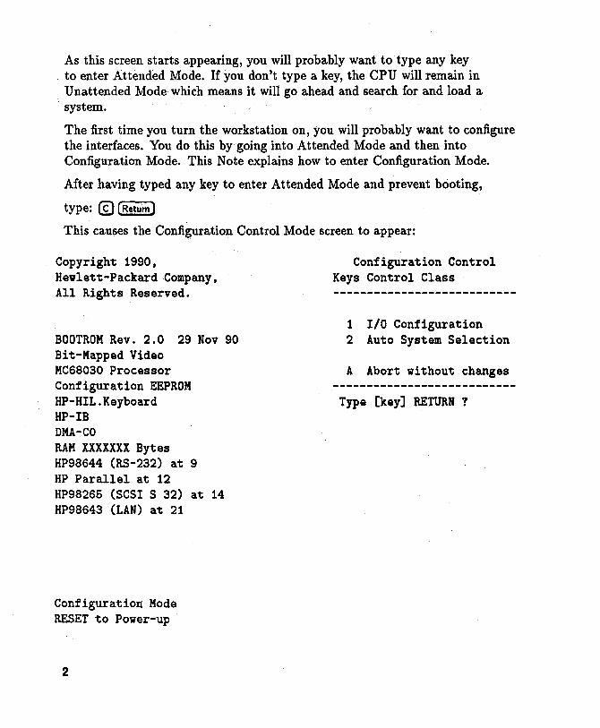
As this screen starts appearing, you will probably want to type any key to enter Attended Mode. If you don't type a key, the CPU will remain in Unattended Mode which means it will go ahead and search for and load a system.
The first time you turn the workstation on, you will probably want to configure the interfaces. You do this by going into Attended Mode and then into Configuration Mode. This Note explains how to enter Configuration Mode.
After having typed any key to enter Attended Mode and prevent booting,
type: © [Return)
This causes the Configuration Control Mode screen to appear:
Copyright 1990, Hewlett-Packard Company, All Rights Reserved.
BOOTROM Rev. 2.0 29 Nov 90 Bit-Mapped Video MC68030 Processor Configuration EEPROM HP-HIL.Keyboard HP-IB DMA-CO RAM XXXXXXX Bytes HP98644 (RS-232) at 9 HP Parallel at 12 HP98265 (SCSI S 32) at 14 HP98643 (LAN) at 21
Configuration Mode RESET to Power-up
2
Configuration Control Keys Control Class
1 I/O Configuration 2 Auto System Selection
A Abort without changes
Type [key] RETURN ?
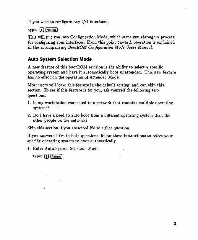
If you wish to configure any 110 interfaces,
type: [) (Return)
This will put you into Configuration Mode, which steps you through a process for configuring your interfaces. From this point onward, operation is explained in the accompanying BootROM Configuration Mode Users Manual.
Auto System Selection Mode
A new feature of this bootROM revision is the ability to select a specific operating system and have it automatically boot unattended. This new feature has no effect on the operation of Attended Mode.
Most users will leave this feature in the default setting, and can skip this section. To see if this feature is for you, ask yourself the following two questions:
1. Is my workstation connected to a network that contains multiple operating systems?
2. Do I have a need to auto boot from a different operating system than the other people on the network?
Skip this section if you answered No to either question.
If you answered Yes to both questions, follow these instructions to select your specific operating system to boot automatically.
1. Enter Auto System Selection Mode:
type: (1) (Return )
3
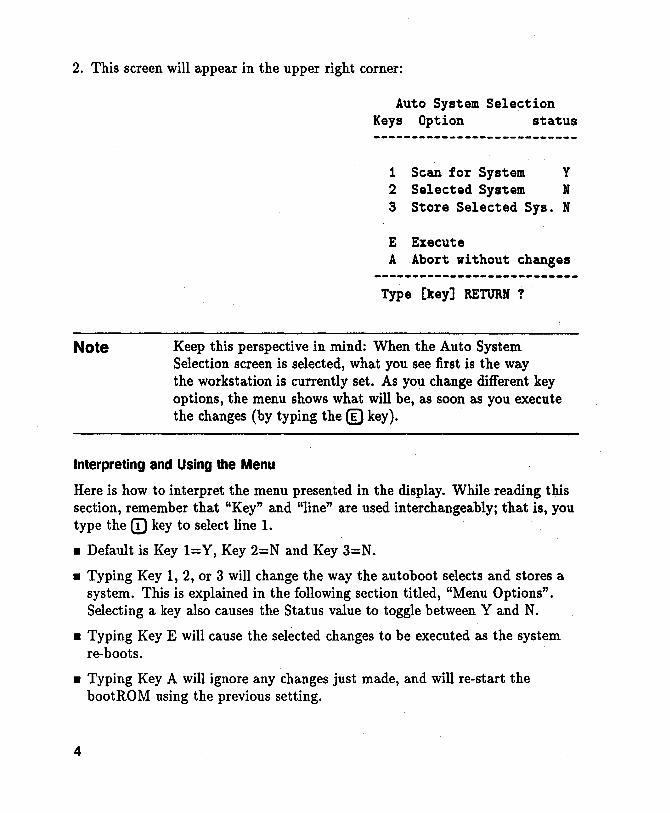
2. This screen will appear in the upper right corner:
Note
Auto System Selection Keys Option status
1 Scan for System Y 2 Selected System N 3 Store Selected Sys. N
E Execute A Abort without changes
Type [key] RETURN ?
Keep this perspective in mind: When the Auto System Selection screen is selected, what you see first is the way the workstation is currently set. As you change different key options, the menu shows what will be, as soon as you execute the changes (by typing the ® key).
Interpreting and Using the Menu
Here is how to interpret the menu presented in the display. While reading this section, remember that "Key" and "line" are used interchangeably; that is, you type the CD key to select line 1.
• Default is Key I=Y, Key 2=N and Key 3=N.
• Typing Key 1, 2, or 3 will change the way the autoboot selects and stores a system. This is explained in the following section titled, "Menu Options". Selecting a key also causes the Status value to toggle between Y and N.
• Typing Key E will cause the selected changes to be executed as the system re-boots.
• Typing Key A will ignore any changes just made, and will re-start the bootRO M using the previous setting.
4
Menu Options
• Key 1= Y tells the workstation to boot the first bootable operating system it finds.
• Key 2= Y tells the workstation to boot a specific operating system.
• Key 3= Y causes the bootRom to store the specified operating system path in the EEPROM. This allows the selected system to auto-boot unattended.
Note that some key combinations are valid but others are either invalid or . meaningless. Here are the valid combinations:
1. Key I=Y and Key 2=Y. This will cause the bootRom to try auto-booting from the selected system once. If the selected system can not be accessed (because its power switch is off or data cable is not connected), then the first bootable system will be booted. (This is the most useful selected system option).
2. Key I=N and Key 2=Y. This will cause the bootRom to try auto-booting from the selected system only, until it boots.
3. Key I=Y and Key 2=N. This default mode causes the bootRom to boot the first bootable system it finds. No selected system specified.
Here are the invalid or meaningless combinations. The bootROM will toggle another line in order to produce a useable combination.
• Key 1 =N and Key 2=N. Key· 1 or Key 2 must be Y. Trying to set both to N is not allowed and the opposite key will be automatically toggled.
• Key 2= Y and Key 3=N. Changing Key 2 to Y will automatically set Key 3 to Y. This means a new system is to be selected, and Key 3= Y says to store that new system in the EEPROM.
System Selection Example
Here is an example of how to select a specific system:
Suppose that the operating system which you wish to select for automatic booting is labelled 2H in the list of boot able operating systems displayed on the right. Furthermore, you want the workstation to try to boot the system once, and if it is not accessible to go on and scan for and boot the default system.
5
This situation is listed as number one in the above list of valid combinations. To set it up, follow these steps:
1. Toggle key 2 status to Y.
Type: ® [Return)
Key 3 status will automatically toggle to Y.
2. Check to make sure key l=Y
3. Execute this combination.
Type: ® [Return)
At this point the screen clears and the system starts re-booting. When hp-hil.keyboard is displayed or the beeper sounds, type the space bar to invoke Attended Mode. Wait until all the devices are listed on the left and all bootable operating systems are listed on the right. The screen at this point looks almost identical to an attended mode bootup screen. The one difference is an additional message on the next to bottom line indicating that the bootROM will store the selection.
4. Select the number-letter combination listed in front of the operating system you want to select. For our example,
type: CD]) (Return)
The workstation stores the selected system path information in the EEPROM while clearing the screen and re-booting. The selected system will now be booted.
This completes the process, and the selected system will continue to boot until a different unattended system is selected.
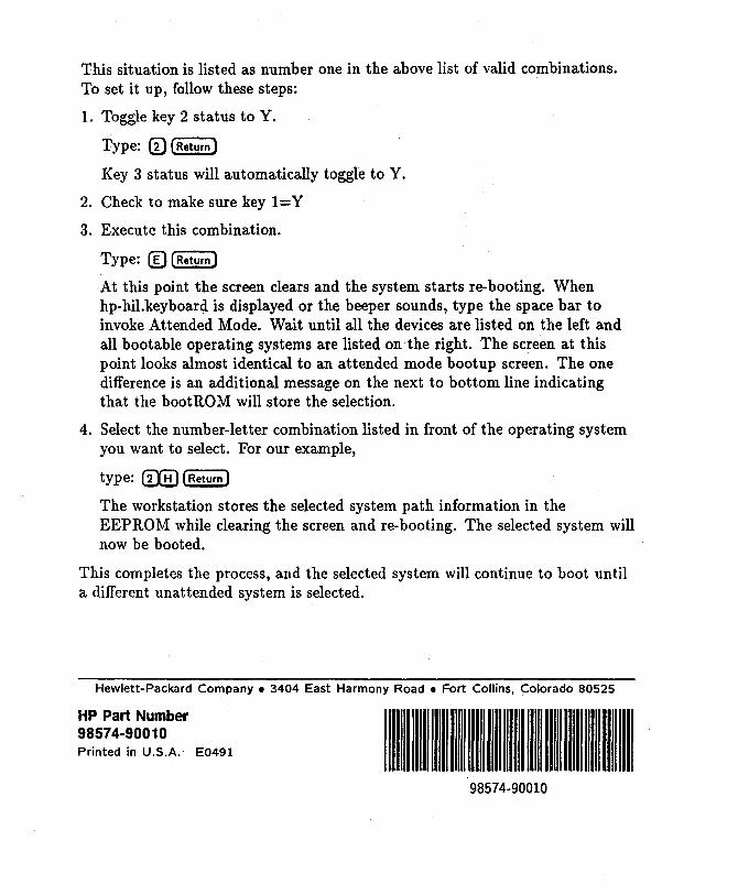
Hewlett-Packard Company. 3404 East Harmony Road • Fort Collins, Colorado 80525
HP Part Number 98574-90010 Printed in U.S.A. E0491 " " " "'" 98574-90010