Embed Size (px)
Citation preview
0.3 MPa
0.3 MPa
0.3 MPa
0.3 MPa
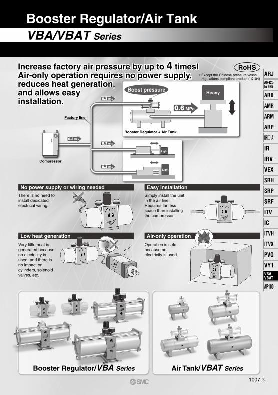
0.6 MPa
Booster Regulator + Air Tank
Heavy
Compressor
Factory line
Light
Light
∗ Except the Chinese pressure vessel regulations compliant product (-X104)
RoHS
VBA/VBAT Series
Booster Regulator/Air Tank
Booster Regulator/VBA Series Air Tank/VBAT Series
No power supply or wiring needed Easy installation
Low heat generation Air-only operation
Very little heat is generated because no electricity is used, and there is no impact on cylinders, solenoid valves, etc.
Operation is safe because no electricity is used.
Simply install the unit in the air line.Requires far less space than installing the compressor.
There is no need to install dedicated electrical wiring.
Increase factory air pressure by up to 4 times!Air-only operation requires no power supply, reduces heat generation, and allows easy installation.
Boost pressure
1007
ARJAR425to 935
ARX
AMR
ARM
ARP
IR-A
IR
IRV
VEX
SRH
SRP
SRF
ITV
IC
ITVX
ITVH
PVQ
VY1VBAVBAT
AP100
VBAVBAT
A
Cylinder tube
Tie-rod guide
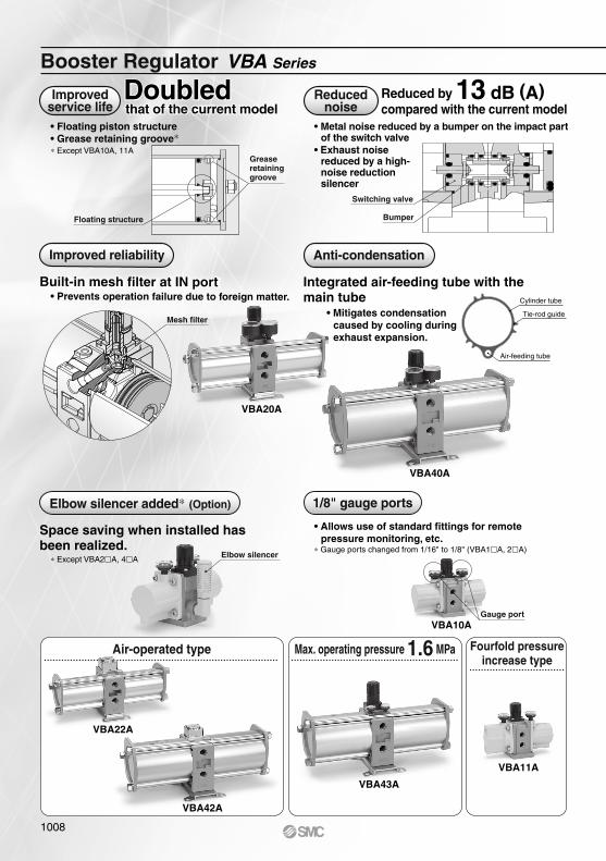
Air-operated type Max. operating pressure 1.6 MPa Fourfold pressureincrease type
Booster Regulator VBA Series
Space saving when installed has been realized.
Elbow silencer added∗ (Option) 1/8" gauge ports
• Allows use of standard fittings for remote pressure monitoring, etc.
∗ Gauge ports changed from 1/16" to 1/8" (VBA1A, 2A)
• Floating piston structure• Grease retaining groove∗∗ Except VBA10A, 11A
Improvedservice life that of the current model
Doubledthat of the current modelDoubled
• Metal noise reduced by a bumper on the impact partof the switch valve
• Exhaust noise reduced by a high-noise reduction silencer
Reducednoise
Reduced by 13 dB (A)compared with the current modelcompared with the current modelReduced by 13 dB (A)
• Mitigates condensation caused by cooling during exhaust expansion.
Integrated air-feeding tube with the main tube• Prevents operation failure due to foreign matter.
Built-in mesh filter at IN port
Improved reliability
Built-in mesh filter at IN port Integrated air-feeding tube with the main tube
Anti-condensation
Air-feeding tube
∗ Except VBA2A, 4A
VBA10A
VBA40A
VBA20A
Grease retaining groove
Floating structure
Mesh filter
Gauge port
Elbow silencer
VBA43A
VBA11A
VBA22A
VBA42A
Switching valve
Bumper
1008
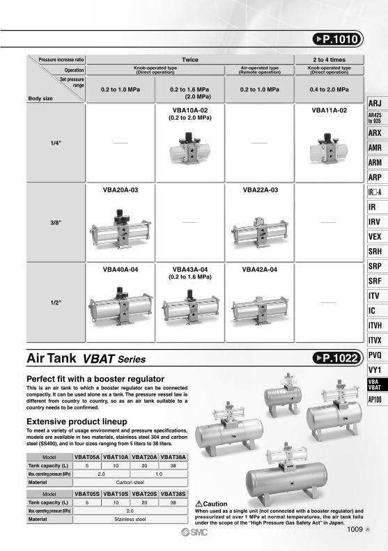
Tank capacity (L)
Max. operating pressure (MPa)
Material
Model VBAT10A
10
VBAT20A
20
Carbon steel
VBAT38A
38
1.02.0
Tank capacity (L)
Max. operating pressure (MPa)
Material
Model VBAT10S
10
VBAT05A
5
VBAT05S
5
VBAT20S
20
VBAT38S
38
2.0
Stainless steel
Body size
Set pressurerange
Operation
Pressure increase ratio
0.2 to 1.0 MPa
Knob-operated type(Direct operation)
Air-operated type(Remote operation)
TwiceKnob-operated type(Direct operation)
2 to 4 times
0.2 to 1.6 MPa(2.0 MPa)
0.2 to 1.0 MPa
VBA10A-02(0.2 to 2.0 MPa)
VBA11A-02
VBA20A-03 VBA22A-03
VBA42A-04VBA43A-04(0.2 to 1.6 MPa)
VBA40A-04
1/4"
3/8"
1/2"
0.4 to 2.0 MPa
Air Tank VBAT Series
When used as a single unit (not connected with a booster regulator) and pressurized at over 1 MPa at normal temperatures, the air tank falls under the scope of the “High Pressure Gas Safety Act” in Japan.
Caution
Perfect fit with a booster regulatorThis is an air tank to which a booster regulator can be connected compactly. It can be used alone as a tank. The pressure vessel law is different from country to country, so as an air tank suitable to a country needs to be confirmed.
Extensive product lineupTo meet a variety of usage environment and pressure specifications, models are available in two materials, stainless steel 304 and carbon steel (SS400), and in four sizes ranging from 5 liters to 38 liters.
P.1010
P.1022
1009
ARJAR425to 935
ARX
AMR
ARM
ARP
IR-A
IR
IRV
VEX
SRH
SRP
SRF
ITV
IC
ITVX
ITVH
PVQ
VY1VBAVBAT
AP100
VBAVBAT
A
Symbol
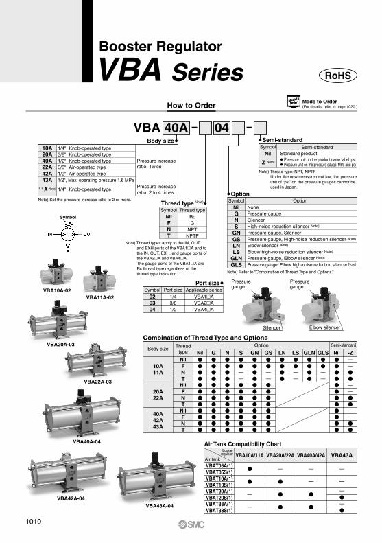
How to Order
Booster Regulator
VBA Series
VBA 0440A
Port size
020304
1/43/81/2
Port sizeVBA1AVBA2AVBA4A
Applicable seriesSymbol
Thread typeRcG
NPTNPTF
Thread type Note)
SymbolNilFNT
1/4", Knob-operated type3/8", Knob-operated type1/2", Knob-operated type3/8", Air-operated type1/2", Air-operated type1/2", Max. operating pressure 1.6 MPa
1/4", Knob-operated type
Pressure increase ratio: Twice
Pressure increase ratio: 2 to 4 times
Body size10A20A40A22A42A43A
11A Note)
Note) Thread type: NPT, NPTFUnder the new measurement law, the pressure unit of “psi” on the pressure gauges cannot be used in Japan.
Semi-standardStandard product¡Pressure unit on the product name label: psi¡Pressure unit on the pressure gauge: MPa and psi
Semi-standardSymbol
Nil
Z Note)
Note) Thread types apply to the IN, OUT, and EXH ports of the VBA1A and to the IN, OUT, EXH, and gauge ports of the VBA2A and VBA4A. The gauge ports of the VBA1A are Rc thread type regardless of the thread type indication.
OptionOption
SymbolNilGNS
GNGSLNLS
GLNGLS
Note) Refer to “Combination of Thread Type and Options.”
Air Tank Compatibility Chart
RoHS
VBA11A-02
VBA20A-03
VBA10A-02
VBA40A-04
VBA22A-03
VBA42A-04VBA43A-04
10A11A
20A22A
40A42A43A
G
Combination of Thread Type and Options
Body sizeOption Semi-standardThread
type NilNilFNT
NilFNT
NilFNT
N
S——
GN
GS——
LN
LS——
GLN
——
NilGLS
-Z——
——
——
Made to Order(For details, refer to page 1020.)
NonePressure gaugeSilencerHigh-noise reduction silencer Note)
Pressure gauge, SilencerPressure gauge, High-noise reduction silencer Note)
Elbow silencer Note)
Elbow high-noise reduction silencer Note)
Pressure gauge, Elbow silencer Note)
Pressure gauge, Elbow high-noise reduction silencer Note)
Elbow silencer
Pressure gauge
Pressure gauge
Silencer
Note) Set the pressure increase ratio to 2 or more.
VBAT05A(1)VBAT05S(1)VBAT10A(1)VBAT10S(1)VBAT20A(1)VBAT20S(1)VBAT38A(1)VBAT38S(1)
VBA20A/22AVBA10A/11A VBA43A
—
—
—
VBA40A/42A
—
—
—
—
—
—
Boosterregulator
Air tank
1010
Related Products/Part No.
Options/Part No.
Standard Specifications
Note) Refer to page 1022 for air tanks, page 223 for mist separators and Best Pneumatics No.7 for exhaust cleaners.Refer to the separate operation manual for the connection method.
Description
Model
Mist separatorExhaust cleaner
For VBA10A-02For VBA11A-02
For VBA20A-03For VBA22A-03
AM250C-02AMC310-03
AM450C-04, 06AMC510-06
AM550C-06, 10AMC610-10
For VBA40A-04For VBA42A-04For VBA43A-04
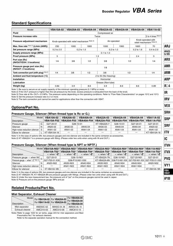
Note 1) Be sure to secure an air supply capacity of the minimum operating pressure (0.1 MPa) or more.Note 2) If the OUT pressure is higher than the set pressure by the knob, excess pressure is exhausted from the back of the knob.Note 3) Flow rate at IN= OUT= 0.5 MPa. The pressure varies depending on the operating conditions. Refer to “Flow Rate Characteristics” on pages 1012 and 1013. Note 4) Set the pressure increase ratio to 2 or more.Note 5) The tank connection port cannot be used for applications other than the connection with VBAT.
Model
Fluid
Pressure increase ratio
Pressure adjustment mechanism
Max. flow rate Note 3) (L/min (ANR))
Set pressure range (MPa)
Supply pressure range (MPa)
Proof pressure (MPa)
Tank connection port (with plug) Note 5)
Ambient and fluid temperature (°C)
Installation
Lubrication
Weight (kg)
Port size (Rc)(IN/OUT/EXH: 3 locations)
Pressure gauge port size (Rc)(IN/OUT: 2 locations)
VBA10A-02 VBA20A-03 VBA40A-04 VBA22A-03 VBA42A-04 VBA11A-02VBA43A-04Compressed air
0.1 to 1.0
2 to 50 (No freezing)
Horizontal
Grease (Non-lube)
Twice
230
0.2 to 2.0
3
1/4
0.84
1000
0.2 to 1.0
1.5
0.2 to 1.0
1900 1000 1900 70
0.4 to 2.0
1600
0.2 to 1.6
2 to 4 times Note 4)
Knob-operated withrelief mechanism Note 2)Knob-operated with relief mechanism Note 2) Air-operated
3/8
3.9
1/2
1/8
3/8 1/2
8.6 3.9 8.6
3
1/4
0.89
2.4
8.6
Note 1) In the case of options GN, two pressure gauges and one silencer are included in the same container as accessories.Note 2) KT-VBA22A-7 is a pressure gauge with fitting. (Please order two units when using with IN and OUT.)
Pressure Gauge, Silencer (When thread type is Rc or G.)Model
DescriptionPressure gaugeSilencerHigh-noise reduction silencerElbow for silencer
GNSL
VBA43A-04VBA43A-F04
VBA42A-04VBA42A-F04
VBA22A-03VBA22A-F03
VBA40A-04VBA40A-F04
VBA20A-03VBA20A-F03
VBA10A-02VBA10A-F02
VBA11A-02VBA11A-F02
G27-20-01AN20-02ANA1-02
KT-VBA10A-18
G27-20-01AN20-02ANA1-02
KT-VBA10A-18
G36-10-01AN30-03ANA1-03
—
AN40-04ANA1-04
—
KT-VBA22A-7AN30-03ANA1-03
—
G36-10-01AN40-04ANA1-04
—
G27-20-01AN40-04ANA1-04
—
Note 1) In the case of options GN, two pressure gauges and one silencer are included in the same container as accessories.Note 2) KT-VBA22A-7N, KT-VBA22A-8N are pressure gauges with fittings. (Please order two units when using with IN and OUT.)Note 3) Under the new measurement law, the pressure unit of “psi” on the pressure gauges cannot be used in Japan.Note 4) Pressure unit on the pressure gauge: MPa and psi
Pressure Gauge, Silencer (When thread type is NPT or NPTF.)Model
Description
G
NSL
VBA10A-N02∗VBA10A-T02∗
∗: when “-Z”
VBA11A-N02∗VBA11A-T02∗
∗: when “-Z”
VBA20A-N03∗VBA20A-T03∗
∗: when “-Z”
VBA40A-N04∗VBA40A-T04∗
∗: when “-Z”
VBA22A-N03∗VBA22A-T03∗
∗: when “-Z”
VBA42A-N04∗VBA42A-T04∗
∗: when “-Z”
VBA43A-N04∗VBA43A-T04∗
∗: when “-Z”G27-20-01
G27-P20-01-X30AN20-N02
—
KT-VBA10A-18N
G27-20-01G27-P20-01-X30
AN20-N02—
KT-VBA10A-18N
G36-10-N01G36-P10-N01-X30
AN30-N03ANA1-N03
—
AN40-N04ANA1-N04
—
KT-VBA22A-7NKT-VBA22A-8N
AN30-N03ANA1-N03
—
G36-10-N01G36-P10-N01-X30
AN40-N04ANA1-N04
—
G27-20-N01G27-P20-N01-X30
AN40-N04ANA1-N04
—
Mist Separator, Exhaust Cleaner
Pressure gauge ∗: when NilPressure gauge ∗: when “-Z” Note 4)
SilencerHigh-noise reduction silencerElbow for silencer
Booster Regulator VBA Series
1/4 3/8 1/2 3/8 1/2 1/4
1011
ARJAR425to 935
ARX
AMR
ARM
ARP
IR-A
IR
IRV
VEX
SRH
SRP
SRF
ITV
IC
ITVX
ITVH
PVQ
VY1VBAVBAT
AP100
VBAVBAT
A
12
11
10
9
8
7
6
5
4
3
2
10
Cha
rge
time
per
10 L
t (
s)
1.0 1.1 1.2 1.3 1.4 1.5 1.6 1.7 1.8 1.9 2.0
Pressure increase ratio P2/P1
1.0
0.8
0.6
0.4
0.2
Out
let p
ress
ure
(MP
a)
0 200 400 600 800 1000 1200
Outlet air flow rate (L/min (ANR))
1.04
1.02
1.0
0.98
0.96
0.94
Out
let p
ress
ure
(MP
a)
0 0.4 0.5 0.6 0.7 0.8 0.9 1
Inlet pressure (MPa)
1.0
0.8
0.6
0.4
0.2
Out
let p
ress
ure
(MP
a)
0 500 1000 1500 2000
Outlet air flow rate (L/min (ANR))
1.04
1.02
1.0
0.98
0.96
0.94
Out
let p
ress
ure
(MP
a)
0 0.4 0.5 0.6 0.7 0.8 0.9 1
Inlet pressure (MPa)
5
4
3
2
1
0
Cha
rge
time
per
10 L
t (
s)
1.0 1.1 1.2 1.3 1.4 1.5 1.6 1.7 1.8 1.9 2.0
Pressure increase ratio P2/P1
60
50
40
30
20
10
0
Cha
rge
time
per
10 L
t (
s)
1.0 1.2 1.4 1.6 1.8 2.0
Pressure increase ratio P2/P1
2
1.5
1
0.5Out
let p
ress
ure
(MP
a)
0 100 200 300 400
Outlet air flow rate (L/min (ANR))
1.1
1.05
1.0
0.95
0.9
0.85
0.8
Out
let p
ress
ure
(MP
a)
0 0.50.4 0.6 0.7 0.8 0.9 1
Inlet pressure (MPa)
P1 = 0.5 MPa
P1 = 0.4 MPa
P1 = 0.3 MPa
VBA20A, 22A
VBA20A, 22A
Flow Rate Characteristics
Charge Characteristics
PressureCharacteristics
Inlet pressure: 0.7 MPaOutlet pressure: 1.0 MPa
Flow rate: 20 L/min (ANR)
Set point
VBA40A, 42A
VBA40A, 42A
P1 = 0.5 MPa
P1 = 0.4 MPaP1 = 0.3 MPa
Flow Rate Characteristics
Charge Characteristics
PressureCharacteristics
Inlet pressure: 0.7 MPaOutlet pressure: 1.0 MPa
Flow rate: 20 L/min (ANR)
Set point
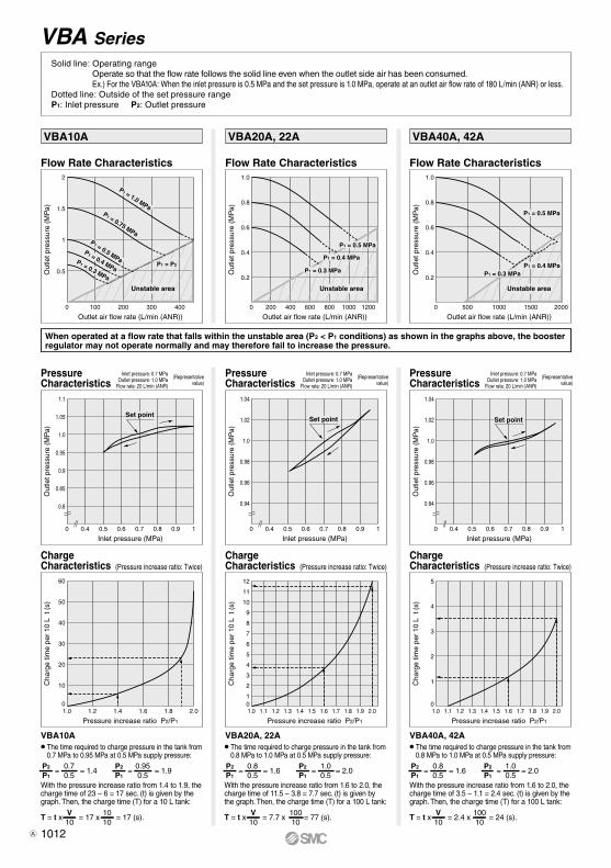
VBA10A
VBA10A
Flow Rate Characteristics
PressureCharacteristics
Charge Characteristics
Inlet pressure: 0.7 MPaOutlet pressure: 1.0 MPa
Flow rate: 20 L/min (ANR)
P1 = 1.0 MPaP1 = 0.75 MPa
P1 = 0.5 MPaP1 = 0.4 MPa
P1 = 0.3 MPa
Set point
(Representativevalue)
(Representativevalue)
(Representativevalue)
P2
P1
0.70.5
= = 1.4 = 1.9 = 1.6 = 2.0P2
P1
0.950.5
=
T = t x = 17 x = 17 (s).V10
1010
P2
P1
0.80.5
=P2
P1
1.00.5
=
T = t x = 7.7 x = 77 (s).V10
10010
P2
P1
0.80.5
= = 1.6 = 2.0P2
P1
1.00.5
=
T = t x = 2.4 x = 24 (s).V10
10010
VBA Series
(Pressure increase ratio: Twice)
P1 = P2
Unstable area
When operated at a flow rate that falls within the unstable area (P2 < P1 conditions) as shown in the graphs above, the booster regulator may not operate normally and may therefore fail to increase the pressure.
Unstable area Unstable area
(Pressure increase ratio: Twice)(Pressure increase ratio: Twice)
The time required to charge pressure in the tank from 0.7 MPa to 0.95 MPa at 0.5 MPa supply pressure:
With the pressure increase ratio from 1.4 to 1.9, the charge time of 23 – 6 = 17 sec. (t) is given by the graph. Then, the charge time (T) for a 10 L tank:
With the pressure increase ratio from 1.6 to 2.0, the charge time of 11.5 – 3.8 = 7.7 sec. (t) is given by the graph. Then, the charge time (T) for a 100 L tank:
With the pressure increase ratio from 1.6 to 2.0, the charge time of 3.5 – 1.1 = 2.4 sec. (t) is given by the graph. Then, the charge time (T) for a 100 L tank:
The time required to charge pressure in the tank from 0.8 MPa to 1.0 MPa at 0.5 MPa supply pressure:
The time required to charge pressure in the tank from 0.8 MPa to 1.0 MPa at 0.5 MPa supply pressure:
Solid line: Operating rangeOperate so that the flow rate follows the solid line even when the outlet side air has been consumed.Ex.) For the VBA10A: When the inlet pressure is 0.5 MPa and the set pressure is 1.0 MPa, operate at an outlet air flow rate of 180 L/min (ANR) or less.
Dotted line: Outside of the set pressure rangeP1: Inlet pressure P2: Outlet pressure
1012A
1.6
1.4
1.2
1
0.8
0.6
0.4
0.2
Out
let p
ress
ure
(MP
a)
0 500 1000 1500 2000 2500 3000
Outlet air flow rate (L/min (ANR))
1.08
1.06
1.04
1.02
1.0
0.98
0.96
0.94
Out
let p
ress
ure
(MP
a)
0 0.4 0.5 0.6 0.7 0.8 0.9 1
Inlet pressure (MPa)
0.1
0.08
0.06
0.04
0.02Max
. pul
satio
n ra
nge
(MP
a)
0 1 2 3 4 5
Capacity (L)
0.1
0.08
0.06
0.04
0.02Max
. pul
satio
n ra
nge
(MP
a)
0 10 20 30 4038
Capacity (L)
5
4
3
2
1
0
Cha
rge
time
per
10 L
t (
s)
1.0 1.1 1.2 1.3 1.4 1.5 1.6 1.7 1.8 1.9 2.0
Pressure increase ratio P2/P1
400
300
200
100
0
Cha
rge
time
per
10 L
t (
s)
1.0 2.0 3.0 4.0
Pressure increase ratio P2/P1
Out
let p
ress
ure
(MP
a)
0 0.4 0.5 0.6 0.7 0.8 0.9 1
Inlet pressure (MPa)
2
1
Out
let p
ress
ure
(MP
a)
0 100 15050
Outlet air flow rate (L/min (ANR))
2.1
2.05
2.0
1.95
1.9
1.85
1.8
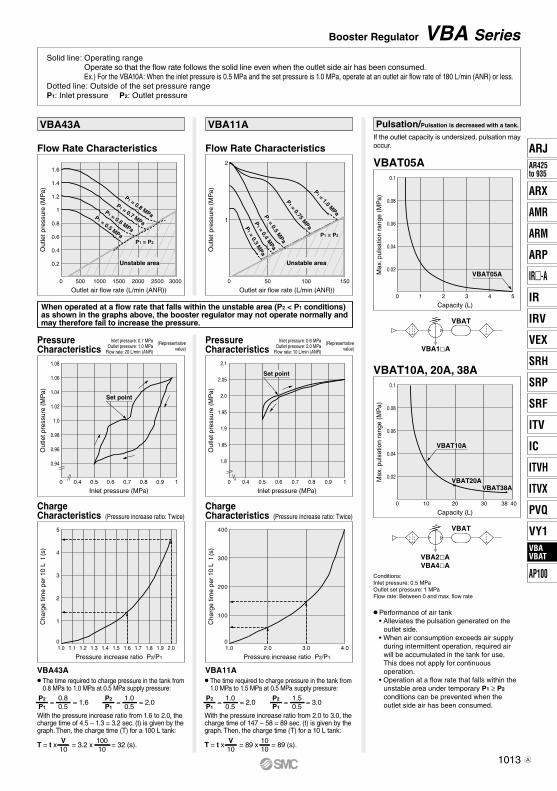
Pulsation/Pulsation is decreased with a tank.
If the outlet capacity is undersized, pulsation may occur.
Conditions: Inlet pressure: 0.5 MPaOutlet set pressure: 1 MPa Flow rate: Between 0 and max. flow rate
• Performance of air tank • Alleviates the pulsation generated on the
outlet side. • When air consumption exceeds air supply
during intermittent operation, required air will be accumulated in the tank for use.This does not apply for continuous operation.
• Operation at a flow rate that falls within the unstable area under temporary P1 ≥ P2 conditions can be prevented when the outlet side air has been consumed.
Flow Rate Characteristics
Charge Characteristics
PressureCharacteristics
P1 = 0.8 MPa
P1 = 0.7 MPa
P1 = 0.6 MPa
P1 = 0.5 MPa
P1 = P2
VBAT05A
VBA43A
VBA43A
VBAT05A
VBAT10A, 20A, 38A
VBAT10A
VBAT20AVBAT38A
VBA11A
VBA11A
Flow Rate Characteristics
Charge Characteristics
PressureCharacteristics
Set point
Set point
P1 = 0.4 M
PaP
1 = 0.5 MPa
P1 = 0.75 M
PaP
1 = 1.0 MPa
P1 = P2
P1 = 0.3 M
Pa
Inlet pressure: 0.6 MPaOutlet pressure: 2.0 MPa
Flow rate: 10 L/min (ANR)
Inlet pressure: 0.7 MPaOutlet pressure: 1.0 MPa
Flow rate: 20 L/min (ANR)
P2
P1
0.80.5
= = 1.6 = 2.0P2
P1
1.00.5
=
T = t x = 3.2 x = 32 (s).V10
10010
= 2.0 = 3.0
T = t x = 89 x = 89 (s).V10
1010
P2
P1
1.00.5
=P2
P1
1.50.5
=
Booster Regulator VBA Series
(Representativevalue)
(Representativevalue)
VBA2AVBA4A
VBAT
VBA1A
VBAT
Solid line: Operating rangeOperate so that the flow rate follows the solid line even when the outlet side air has been consumed.Ex.) For the VBA10A: When the inlet pressure is 0.5 MPa and the set pressure is 1.0 MPa, operate at an outlet air flow rate of 180 L/min (ANR) or less.
Dotted line: Outside of the set pressure rangeP1: Inlet pressure P2: Outlet pressure
(Pressure increase ratio: Twice) (Pressure increase ratio: Twice)
The time required to charge pressure in the tank from 0.8 MPa to 1.0 MPa at 0.5 MPa supply pressure:
With the pressure increase ratio from 1.6 to 2.0, the charge time of 4.5 – 1.3 = 3.2 sec. (t) is given by the graph. Then, the charge time (T) for a 100 L tank:
With the pressure increase ratio from 2.0 to 3.0, the charge time of 147 – 58 = 89 sec. (t) is given by the graph. Then, the charge time (T) for a 10 L tank:
The time required to charge pressure in the tank from 1.0 MPa to 1.5 MPa at 0.5 MPa supply pressure:
When operated at a flow rate that falls within the unstable area (P2 < P1 conditions) as shown in the graphs above, the booster regulator may not operate normally and may therefore fail to increase the pressure.
1013
Unstable area Unstable area
ARJAR425to 935
ARX
AMR
ARM
ARP
IR-A
IR
IRV
VEX
SRH
SRP
SRF
ITV
IC
ITVX
ITVH
PVQ
VY1VBAVBAT
AP100
VBAVBAT
A
Tc Ts
Pre
ssur
eS
trok
e
Upper limit of pressure inside the tank P3
Inlet pressure P1
Time
Necessary supply pressure to cylinder P2
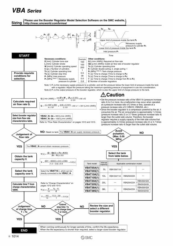
Sizing ( )
END
START
NO NO
NO
YES
YES YES
YES
When running continuously for longer periods of time, confirm the life expectancy. When the life expectancy is shorter than required, select a larger sized booster regulator.
Select the tank from table below.
Judgement offlow rate
Extendstop time Ts
up to charge timeT or more.
Avoidpulsation.(Max. 0.05
MPa)
Judgementof charge time
T ≤ Ts
Provide requisite conditions for selection.
Calculate required air flow rate Q.
Select booster regulator size from flow rate characteristics table.
Obtain the tank capacity V.
Select the tank capacity over V.
Calculate time T from charge characteristics table.
Review the size and select a different booster regulator.
• Set the pressure increase ratio of the VBA11A (pressure increase ratio 4) to 2 or more. As a malfunction may occur when operated at a pressure increase ratio of 2 times or less, operate at a pressure increase ratio of 2 (VBA10, VBA20A, etc.).
• Since the booster regulator is a compressor powered by the air, it consumes the air. The air consumption is approximately 1.2 times (pressure increase ratio 2) or 3.7 times (pressure increase ratio 4) larger than the outlet side volume. Therefore, the booster regulator requires a supply capacity of the inlet side volume that is approximately 2.2 times (pressure increase ratio 2) or 4.7 times (pressure increase ratio 4) larger than the outlet side volume.
Please use the Booster Regulator Model Selection Software on the SMC website, http://mssc.smcworld.com/brmss/
Caution
Lower limit of pressure inside the tank P2
1001002001
0.5300.50.8
ExampleNecessary conditions:D [mm]: Cylinder bore sizeL [mm]: Cylinder strokeW [mm/s]: Cylinder operating speedC [pc.]: Number of cylindersTc [s]: Cylinder operating timeTs [s]: Cylinder stop timeP1 [MPa]: Inlet pressureP2 [MPa] Note 1): Necessary supply
pressure to cylinder
Note 1) P2 is the necessary supply pressure to a cylinder, and set the pressure below the lower limit of pressure inside the tank with a regulator. Adjust the pressure taking the maximum operating pressure of equipment in use into consideration.Note 2) P3 is the output pressure of the booster regulator, which is also the upper limit of charge pressure to the tank.
Other conditions:Q [L/min (ANR)]: Required air flow rateQb [L/min (ANR)]: Outlet air flow rate of booster regulatorTc [s]: Cylinder operating timeK: Cylinder double-acting: 2, single-acting: 1P3 [MPa] Note 2): Tank charge pressureT1 [s]: Time to charge (Time to charge to P2)T2 [s]: Time to charge (Time to charge to P3)T [s]: Time to charge (Time to charge from P2 to P3)Z: Number of booster regulators
Q [L/min (ANR)] = π x D2 x W x (P2 + 0.101) x 60 x C
4 x 10⁶ 0.101
Q = π x 1002 x 200 (0.8 + 0.101) x 60 x 1 = 841 [L/min (ANR)]x
4 x 10⁶ 0.101
Refer to “Flow Rate Characteristics” on pages 1012 and 1013.
VBA2A: Qb = 600 [L/min (ANR)]VBA4A: Qb = 1050 [L/min (ANR)]
NO: Need no tank The VBA4A can supply necessary pressure.
The VBA2A cannot obtain necessary pressure.
(P3 – P2) x 9.9V [L] =
(Q – Qb/2) x (Tc x K/60)
V = = 4.6 [L](1.0 – 0.8) x 9.9
Select the VBAT10, which can be directly connected to the VBA2A.
(841 – 600/2) x (0.5 x 2/60)
Refer to “Charge Characteristics” on pages 1012 and 1013.
T = ( ) x = 3.5 [s]
T [s] = ( ) x T2 – T1V10
4.610
Z
11.5 – 3.81
VBA Series
øD
LP2P3P1
Tank model
VBAT05A(1)VBAT05S(1)VBAT10A(1)VBAT10S(1)VBAT20A(1)VBAT20S(1)VBAT38A(1)VBAT38S(1)
VBA10A/11A
VBA10A/11A
—
—
—
VBA20A/22A
VBA20A/22A
VBA20A/22A
—
—
VBA40A/42A
VBA40A/42A/43A
VBA40A/42A
VBA40A/42A/43A
Applicable combination modelInternalcapacity
5L
10L
20L
38L
1014B
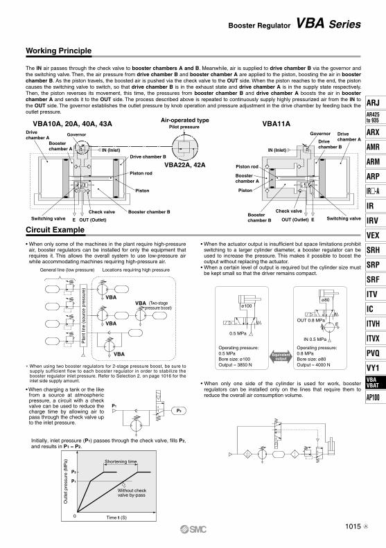
VBA22A, 42A
Air-operated typePilot pressure
IN (Inlet)
Governor
Booster chamber A
Drivechamber A
Switching valve
Piston
Drive chamber B
Booster chamber BCheck valve
OUT (Outlet)E
Piston rod
General line (low pressure) Locations requiring high pressure
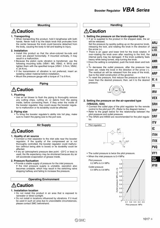
Shortening time
Without check valve by-pass
Time t (S)
Out
let p
ress
ure
(MP
a)
P2
P1
0
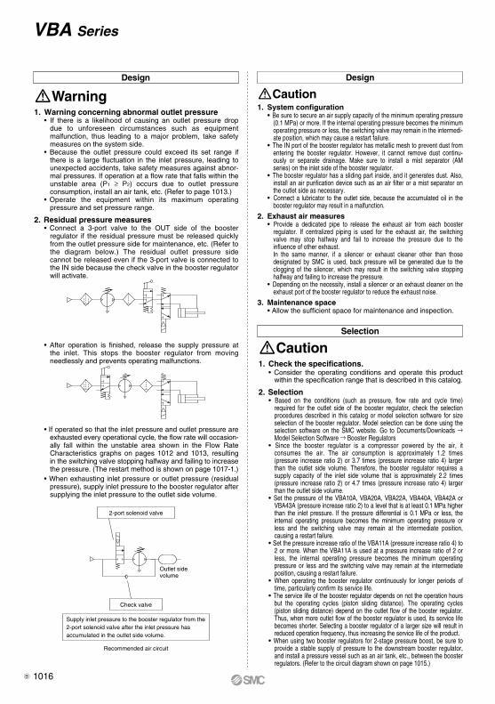
Operating pressure: 0.5 MPaBore size: ø100Output ≈ 3850 N
Operating pressure:0.8 MPaBore size: ø80Output ≈ 4000 N
Equivalentoutput
0.5 MPa
ø100
IN 0.5 MPa
E
ø80
OUT 0.8 MPa
P2
P1
VBA
VBA
VBA
Circuit Example
Working Principle
The IN air passes through the check valve to booster chambers A and B. Meanwhile, air is supplied to drive chamber B via the governor and the switching valve. Then, the air pressure from drive chamber B and booster chamber A are applied to the piston, boosting the air in booster chamber B. As the piston travels, the boosted air is pushed via the check valve to the OUT side. When the piston reaches to the end, the piston causes the switching valve to switch, so that drive chamber B is in the exhaust state and drive chamber A is in the supply state respectively. Then, the piston reverses its movement, this time, the pressures from booster chamber B and drive chamber A boosts the air in booster chamber A and sends it to the OUT side. The process described above is repeated to continuously supply highly pressurized air from the IN to the OUT side. The governor establishes the outlet pressure by knob operation and pressure adjustment in the drive chamber by feeding back the outlet pressure.
VBA10A, 20A, 40A, 43A
Initially, inlet pressure (P1) passes through the check valve, fills P2, and results in P1 = P2.
• When only some of the machines in the plant require high-pressure air, booster regulators can be installed for only the equipment that requires it. This allows the overall system to use low-pressure air while accommodating machines requiring high-pressure air.
• When the actuator output is insufficient but space limitations prohibit switching to a larger cylinder diameter, a booster regulator can be used to increase the pressure. This makes it possible to boost the output without replacing the actuator.
• When a certain level of output is required but the cylinder size must be kept small so that the driver remains compact.
• When charging a tank or the like from a source at atmospheric pressure, a circuit with a check valve can be used to reduce the charge time by allowing air to pass through the check valve up to the inlet pressure.
• When only one side of the cylinder is used for work, booster regulators can be installed only on the lines that require them to reduce the overall air consumption volume.
Booster Regulator VBA Series
(Two-stagepressure boost)
VBA
Pla
nt li
ne (
sour
ce p
ress
ure)
Piston rod
EOUT (Outlet)
Check valveBooster chamber B
Drive chamber B
Piston
Switching valve
Drive chamber A
Booster chamber A
Governor
IN (Inlet)
VBA11A
∗ When using two booster regulators for 2-stage pressure boost, be sure to supply sufficient flow to each booster regulator in order to stabilize the booster regulator inlet pressure. Refer to Selection 2. on page 1016 for the inlet side supply amount.
1015
ARJAR425to 935
ARX
AMR
ARM
ARP
IR-A
IR
IRV
VEX
SRH
SRP
SRF
ITV
IC
ITVX
ITVH
PVQ
VY1VBAVBAT
AP100
VBAVBAT
A
Outlet side volume
2-port solenoid valve
Recommended air circuit
Check valve
Supply inlet pressure to the booster regulator from the 2-port solenoid valve after the inlet pressure has accumulated in the outlet side volume.
Design
Warning1. Warning concerning abnormal outlet pressure
• If there is a likelihood of causing an outlet pressure drop due to unforeseen circumstances such as equipment malfunction, thus leading to a major problem, take safety measures on the system side.
• Because the outlet pressure could exceed its set range if there is a large fluctuation in the inlet pressure, leading to unexpected accidents, take safety measures against abnor-mal pressures. If operation at a flow rate that falls within the unstable area (P1 ≥ P2) occurs due to outlet pressure consumption, install an air tank, etc. (Refer to page 1013.)
• Operate the equipment within its maximum operating pressure and set pressure range.
2. Residual pressure measures• Connect a 3-port valve to the OUT side of the booster
regulator if the residual pressure must be released quickly from the outlet pressure side for maintenance, etc. (Refer to the diagram below.) The residual outlet pressure side cannot be released even if the 3-port valve is connected to the IN side because the check valve in the booster regulator will activate.
• After operation is finished, release the supply pressure at the inlet. This stops the booster regulator from moving needlessly and prevents operating malfunctions.
• If operated so that the inlet pressure and outlet pressure are exhausted every operational cycle, the flow rate will occasion-ally fall within the unstable area shown in the Flow Rate Characteristics graphs on pages 1012 and 1013, resulting in the switching valve stopping halfway and failing to increase the pressure. (The restart method is shown on page 1017-1.)
• When exhausting inlet pressure or outlet pressure (residual pressure), supply inlet pressure to the booster regulator after supplying the inlet pressure to the outlet side volume.
Selection
Caution1. Check the specifications.
• Consider the operating conditions and operate this product within the specification range that is described in this catalog.
2. Selection• Based on the conditions (such as pressure, flow rate and cycle time)
required for the outlet side of the booster regulator, check the selection procedures described in this catalog or model selection software for size selection of the booster regulator. Model selection can be done using the selection software on the SMC website. Go to Documents/Downloads → Model Selection Software → Booster Regulators
• Since the booster regulator is a compressor powered by the air, it consumes the air. The air consumption is approximately 1.2 times (pressure increase ratio 2) or 3.7 times (pressure increase ratio 4) larger than the outlet side volume. Therefore, the booster regulator requires a supply capacity of the inlet side volume that is approximately 2.2 times (pressure increase ratio 2) or 4.7 times (pressure increase ratio 4) larger than the outlet side volume.
• Set the pressure of the VBA10A, VBA20A, VBA22A, VBA40A, VBA42A or VBA43A (pressure increase ratio 2) to a level that is at least 0.1 MPa higher than the inlet pressure. If the pressure differential is 0.1 MPa or less, the internal operating pressure becomes the minimum operating pressure or less and the switching valve may remain at the intermediate position, causing a restart failure.
• Set the pressure increase ratio of the VBA11A (pressure increase ratio 4) to 2 or more. When the VBA11A is used at a pressure increase ratio of 2 or less, the internal operating pressure becomes the minimum operating pressure or less and the switching valve may remain at the intermediate position, causing a restart failure.
• When operating the booster regulator continuously for longer periods of time, particularly confirm its service life.
• The service life of the booster regulator depends on not the operation hours but the operating cycles (piston sliding distance). The operating cycles (piston sliding distance) depend on the outlet flow of the booster regulator. Thus, when more outlet flow of the booster regulator is used, its service life becomes shorter. Selecting a booster regulator of a larger size will result in reduced operation frequency, thus increasing the service life of the product.
• When using two booster regulators for 2-stage pressure boost, be sure to provide a stable supply of pressure to the downstream booster regulator, and install a pressure vessel such as an air tank, etc., between the booster regulators. (Refer to the circuit diagram shown on page 1015.)
VBA Series
1. System configuration• Be sure to secure an air supply capacity of the minimum operating pressure
(0.1 MPa) or more. If the internal operating pressure becomes the minimum operating pressure or less, the switching valve may remain in the intermedi-ate position, which may cause a restart failure.
• The IN port of the booster regulator has metallic mesh to prevent dust from entering the booster regulator. However, it cannot remove dust continu-ously or separate drainage. Make sure to install a mist separator (AM series) on the inlet side of the booster regulator.
• The booster regulator has a sliding part inside, and it generates dust. Also, install an air purification device such as an air filter or a mist separator on the outlet side as necessary.
• Connect a lubricator to the outlet side, because the accumulated oil in the booster regulator may result in a malfunction.
2. Exhaust air measures• Provide a dedicated pipe to release the exhaust air from each booster
regulator. If centralized piping is used for the exhaust air, the switching valve may stop halfway and fail to increase the pressure due to the influence of other exhaust. In the same manner, if a silencer or exhaust cleaner other than those designated by SMC is used, back pressure will be generated due to the clogging of the silencer, which may result in the switching valve stopping halfway and failing to increase the pressure.
• Depending on the necessity, install a silencer or an exhaust cleaner on the exhaust port of the booster regulator to reduce the exhaust noise.
3. Maintenance space• Allow the sufficient space for maintenance and inspection.
CautionDesign
1016B
1
0.9
0.8
0.7
0.6
0.5
0.5
0.4
0.4
0.3
0.3
0.2
0.2Pilot pressure MPa
0.1
0.10
Out
let p
ress
ure
MP
a (Q
= 0
)
SMC
HighLow
1. Setting the pressure on the knob-operated type• If air is supplied to the product in the shipped state, the air
will be released.Set the pressure by quickly pulling up on the governor knob, releasing the lock, and rotating the knob in the direction of the arrow (+).
• There is an upper and lower limit for the knob rotation. If over-rotating the knob even after reaching to the limit, the internal parts may be damaged. If the knob suddenly feels heavy while being turned, stop turning the knob.
• Once the setting is completed, push the knob down and lock it.
• To decrease the outlet pressure, after the pressure has been set, rotate the knob in the direction of the arrow (–). The residual air will be released from the area of the knob, due to the relief construction of the governor.
• To reset the pressure, first reduce the pressure so that it is lower than the desired pressure; then, set it to the desired pressure.
Caution
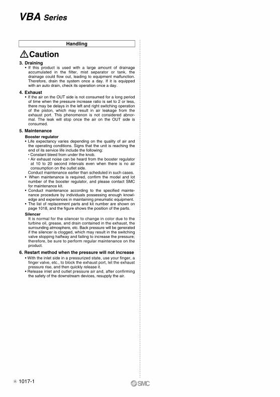
2. Setting the pressure on the air-operated type (VBA22A, 42A)• Connect the outlet pipe of the pilot regulator for the remote
control to the pilot port (P). (Refer to the diagram below.)• Refer to the graph below for the relationship between the
pilot pressure and outlet pressure.• The AR20 and AW20 are recommended for the pilot regula-
tor.
Pilot regulator
• The outlet pressure is twice the pilot pressure.• When the inlet pressure is 0.4 MPa:
Pilot pressure0.2 MPa to 0.4 MPa
Outlet pressure0.4 MPa to 0.8 MPa
Booster Regulator VBA Series
P
E
IN OUT
HandlingMounting
Caution1. Transporting
• When transporting this product, hold it lengthwise with both hands. Never hold it by the black knob that protrudes from the center because the knob could become detached from the body, causing the body to fall and leading to injury.
2. Installation • Install this product so that the silver-colored tie-rods and
cover are placed horizontally. If mounted vertically, it may result in a malfunction.
• Because the piston cycle vibration is transferred, use the following mounting bolts (VBA1: M5; VBA2, 4: M10) and tighten them with the specified torque (VBA1: 3 N·m; VBA2, 4: 24 N·m).
• If the transmission of vibration is not preferred, insert an isolating rubber material before installation.
• Mount the pressure gauge with a torque of 7 to 9 N·m.
Piping
Caution1. Flushing
• Use an air blower to flush the piping to thoroughly remove any cutting chips, cutting oil, or debris from the piping inside, before connecting them. If they enter the inside of the booster regulator, they could cause the booster regula-tor to malfunction or its durability could be affected.
2. Piping size• To bring the booster regulator’s ability into full play, make
sure to match the piping size to the port size.
Air Supply
Caution1. Quality of air source
• Connect a mist separator to the inlet side near the booster regulator. If the quality of the compressed air is not thoroughly controlled, the booster regulator could malfunc-tion (without being able to boost) or its durability could be affected.
• If dry air (atmospheric pressure dew point: –23°C or less) is used, the life expectancy may be shortened because dry air will accelerate evaporation of grease inside.
2. Pressure fluctuation• Provide a stable supply of pressure for the inlet pressure.
If the inlet pressure supply is unstable, operation also becomes unstable, which may result in the switching valve stopping halfway and failing to increase the pressure.
Operating Environment
Caution1. Installation location
• Do not install this product in an area that is exposed to rainwater or direct sunlight.
• Do not install in locations influenced by vibrations. If it must be used in such an area due to unavoidable circumstances, please contact SMC beforehand.
1017
ARJAR425to 935
ARX
AMR
ARM
ARP
IR-A
IR
IRV
VEX
SRH
SRP
SRF
ITV
IC
ITVX
ITVH
PVQ
VY1VBAVBAT
AP100
VBAVBAT
B
Caution
VBA Series
Handling
3. Draining• If this product is used with a large amount of drainage
accumulated in the filter, mist separator or tank, the drainage could flow out, leading to equipment malfunction. Therefore, drain the system once a day. If it is equipped with an auto drain, check its operation once a day.
4. Exhaust• If the air on the OUT side is not consumed for a long period
of time when the pressure increase ratio is set to 2 or less, there may be delays in the left and right switching operation of the piston, which may result in air leakage from the exhaust port. This phenomenon is not considered abnor-mal. The leak will stop once the air on the OUT side is consumed.
5. MaintenanceBooster regulator• Life expectancy varies depending on the quality of air and
the operating conditions. Signs that the unit is reaching the end of its service life include the following:• Constant bleed from under the knob.• Air exhaust noise can be heard from the booster regulator
at 10 to 20 second intervals even when there is no air consumption on the outlet side.
Conduct maintenance earlier than scheduled in such cases.• When maintenance is required, confirm the model and lot
number of the booster regulator, and please contact SMC for maintenance kit.
• Conduct maintenance according to the specified mainte-nance procedure by individuals possessing enough knowl-edge and experiences in maintaining pneumatic equipment.
• The list of replacement parts and kit number are shown on page 1018, and the figure shows the position of the parts.
SilencerIt is normal for the silencer to change in color due to the turbine oil, grease, and drain contained in the exhaust, the surrounding atmosphere, etc. Back pressure will be generated if the silencer is clogged, which may result in the switching valve stopping halfway and failing to increase the pressure; therefore, be sure to perform regular maintenance on the product.
6. Restart method when the pressure will not increase• With the inlet side in a pressurized state, use your finger, a
finger valve, etc., to block the exhaust port, let the exhaust pressure rise, and then quickly release it.
• Release inlet and outlet pressure air and, after confirming the safety of the downstream devices, resupply the air.
1017-1A

wq r e w t r eu qt
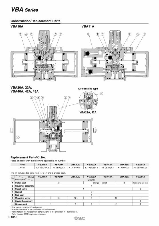
Construction/Replacement Parts
VBA10A VBA11A
q
wryqt e
Air-operated type
VBA22A, 42A
VBA20A, 22A, VBA40A, 42A, 43A
Replacement Parts/Kit No.
The kit includes the parts from q to u and a grease pack.
ModelNo.
1
2
3
4
5
6
7
—
Piston seal
Governor assembly
Check valve
Gasket
Rod seal
Mounting screw
Cover C assembly
Grease pack
Description
Place an order with the following applicable kit number.
Model
Kit no.
VBA43A VBA11AVBA42AVBA22AVBA40AVBA20AVBA10AKT-VBA10A-1 KT-VBA20A-1 KT-VBA40A-1 KT-VBA22A-1 KT-VBA42A-1 KT-VBA43A-1 KT-VBA11A-20
VBA43A VBA11AVBA42AVBA22AVBA40AVBA20AVBA10AQuantity
2
2
1
8— 8 12
1
—
2 1 2
1
—
1
1
12
1 each large and small
2
2 large 1 small 2
∗ The grease pack has 10 g of grease.∗ Make sure to refer to the procedure for maintenance.∗ For details on the replacement parts kit, refer to the procedure for maintenance.∗ Refer to page 1011 for pressure gauges.
4
VBA Series
1018A
IN side gauge port1/8
300
39
OUT side gauge port1/8
Pressure gauge (Option)
3.2
73
53
IN side gauge port1/8
OUT side gauge port1/8
Pressure gauge (Option)
3.2
404
40
116
96
OUT port1/4
IN port1/4
4 x ø5.5 EXH port1/4
Silencer (Option)
(When silencer installed: 107)(When high-noise reduction
silencer installed: 126)
287
2327
60
70
22
113
(When silencer installed: 107)(When high-noise reduction
silencer installed: 126)
Silencer (Option)
4 x ø5.5
IN port1/4OUT port1/4
EXH port1/4
287
2327
60
70
22
113
OUT port3/8
IN port3/8
Silencer (Option)
4 x ø12EXH port3/8
15
(When silencer installed: 153.5)(When high-noise reduction
silencer installed: 179)
28
176
4346 21
98
118
24
OUT port1/2
IN port1/2
Silencer (Option)
EXH port1/2
8
4 x ø12
(When silencer installed: 200)(When high-noise reduction
silencer installed: 230)
43
22
62.8
62
215
32
150
130
IN port1/4OUT port1/4
Elbow silencer (Option)
EXH port1/4
4 x ø5.5
113
2327
(97)
70
60
22
287
IN port1/4OUT port1/4
Elbow silencer (Option)
EXH port1/4
4 x ø5.5
113
2327
(97)
70
60
22
287
Pressure gauge (Option)
8.5
150
60
50
40
IN side gauge port
Rc 1/8
OUT side gauge portRc 1/8
Pressure gauge (Option)33 30
8.5
50
40
150
IN side gauge port
Rc 1/8
OUT side gauge portRc 1/8
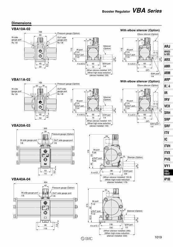
Dimensions
VBA10A-02
VBA11A-02
VBA20A-03
VBA40A-04
With elbow silencer (Option)
With elbow silencer (Option)
Booster Regulator VBA Series
1019
ARJAR425to 935
ARX
AMR
ARM
ARP
IR-A
IR
IRV
VEX
SRH
SRP
SRF
ITV
IC
ITVX
ITVH
PVQ
VY1VBAVBAT
AP100
VBAVBAT
OUT side gauge port1/8
IN side gauge port1/8
300
39 Pressure gauge (Option)
53
73 3.2
IN side gauge port1/8
OUT side gauge port1/8
404
40 Pressure gauge (Option)
96
116 3.2
OUT side gauge port1/8
IN side gauge port1/8
40
404
Pressure gauge (Option)
96
116 3.2
EXH port3/8
OUT port3/8
IN port3/8
(When silencer installed: 153.5)(When high-noise reduction
silencer installed: 179)
28
139
4346
21
4 x ø1298
118
24
15Silencer (Option)
22
EXH port1/2
OUT port1/2
IN port1/2
(When silencer installed: 200)(When high-noise reduction
silencer installed: 230)
43
172 62
62.8
4 x ø12 130
150
32
Silencer (Option)8
EXH port1/2
OUT port1/2
IN port1/2
(When silencer installed: 200)(When high-noise reduction
silencer installed: 230)
43
221
6262
.8
22
4 x ø12 130
150
32
Silencer (Option)8
Pilot port
59
1/8
85Pilot port1/8
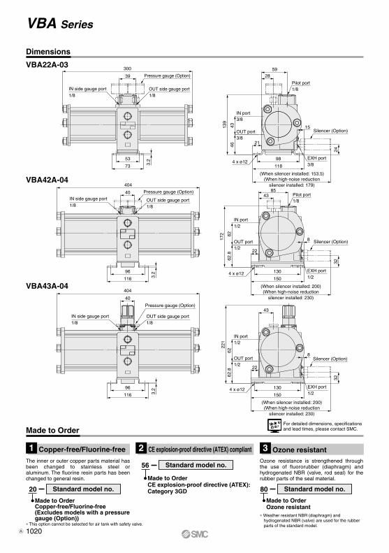
Dimensions
VBA22A-03
VBA42A-04
VBA43A-04
Made to OrderFor detailed dimensions, specifications and lead times, please contact SMC.
The inner or outer copper parts material has been changed to stainless steel or aluminum. The fluorine resin parts has been changed to general resin.
20
Made to OrderCopper-free/Fluorine-free(Excludes models with a pressure gauge (Option))
56
Made to OrderCE explosion-proof directive (ATEX): Category 3GD
Ozone resistance is strengthened through the use of fluororubber (diaphragm) and hydrogenated NBR (valve, rod seal) for the rubber parts of the seal material.
∗ This option cannot be selected for air tank with safety valve.
∗ Weather resistant NBR (diaphragm) and hydrogenated NBR (valve) are used for the rubber parts of the standard model.
80
Made to OrderOzone resistant
Standard model no.
Standard model no.
Standard model no.
Copper-free/Fluorine-free1 CE explosion-proof directive (ATEX) compliant2 Ozone resistant3
VBA Series
1020A
1021
ARJAR425to 935
ARX
AMR
ARM
ARP
IR-A
IR
IRV
VEX
SRH
SRP
SRF
ITV
IC
ITVX
ITVH
PVQ
VY1VBAVBAT
AP100
VBAVBAT
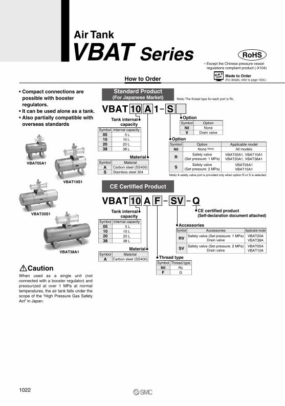
∗ Except the Chinese pressure vesselregulations compliant product (-X104)
Air Tank
VBAT SeriesHow to Order
VBAT05A1
VBAT10S1
VBAT38A1
VBAT20S1
When used as a single unit (not connected with a booster regulator) and pressurized at over 1 MPa at normal temperatures, the air tank falls under the scope of the “High Pressure Gas Safety Act” in Japan.
Caution
• Compact connections are possible with booster regulators.
• It can be used alone as a tank. • Also partially compatible with
overseas standards
RoHS
VBAT 10 A 1
MaterialCarbon steel (SS400)Stainless steel 304
MaterialSymbol
AS
MaterialCarbon steel (SS400)
MaterialSymbol
A
Tank internalcapacity
Tank internalcapacity
Internal capacity5 L
10 L20 L38 L
Symbol05102038
S
Note) A safety valve port is provided only when option R or S is selected.
Option Applicable model
VBAT05A1, VBAT10A1VBAT20A1, VBAT38A1
OptionSymbol
None Note)
Safety valve(Set pressure: 1 MPa)
All modelsNil
R
Safety valve(Set pressure: 2 MPa)
VBAT05A1VBAT10A1S
Accessories
Safety valve (Set pressure: 1 MPa)Drain valve
Applicable model
VBAT20AVBAT38A
AccessoriesSymbol
RV
Safety valve (Set pressure: 2 MPa)Drain valve
VBAT05AVBAT10ASV
CE certified product(Self-declaration document attached)
OptionNone
Drain valve
OptionSymbol
NilV
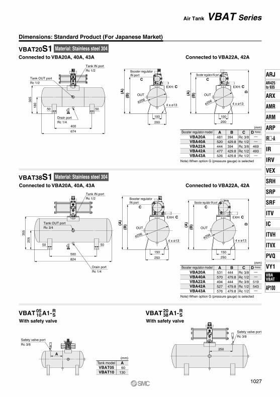
VBAT 10 FA Q
Standard Product(For Japanese Market)
CE Certified Product
Note) The thread type for each port is Rc.
SV
Thread typeRcG
Thread typeSymbol
NilF
Made to Order(For details, refer to page 1024.)
Internal capacitySymbol05102038
5 L10 L20 L38 L
1022
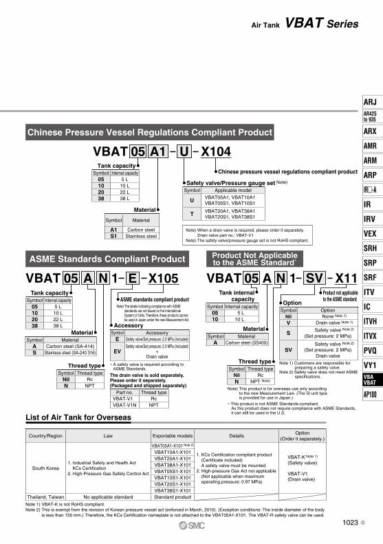
Chinese Pressure Vessel Regulations Compliant Product
Note) When a drain valve is required, please order it separately.Drain valve part no.: VBAT-V1
Note) The safety valve/pressure gauge set is not RoHS compliant.
Note 1) VBAT-K is not RoHS compliant.Note 2) This is exempt from the revision of Korean pressure vessel act (enforced in March, 2010). (Exception conditions: The inside diameter of the body
is less than 150 mm.) Therefore, the KCs Certification nameplate is not attached to the VBAT05A1-X101. The VBAT-R safety valve can be used.
List of Air Tank for Overseas
Product Not Applicableto the ASME Standard*
Material
Tank internalcapacity
Product not applicableto the ASME standard
VBAT 05 N 1A X11SV
Thread type
Note) This product is for overseas use only according to the new Measurement Law. (The SI unit type is provided for use in Japan.)
Option
Note 1) Customers are responsible for preparing a safety valve.
Note 2) Safety valve does not meet ASME specifications.
Symbol OptionNil None Note 1)
V Drain valve Note 1)
S Safety valve Note 2)
(Set pressure: 2 MPa)
SVSafety valve Note 2)
(Set pressure: 2 MPa)Drain valve
Symbol Thread typeNil RcN NPT Note)
Symbol Internal capacity05 5 L10 10 L
Symbol MaterialA Carbon steel (SS400)
Symbol Internal capacity05 5 L10 10 L20 22 L38 38 L
Symbol Applicable model
U VBAT05A1, VBAT10A1VBAT05S1, VBAT10S1
T VBAT20A1, VBAT38A1VBAT20S1, VBAT38S1
Country/Region Law Exportable models DetailsOption
(Order it separately.)
South Korea1. Industrial Safety and Health Act
KCs Certification2. High-Pressure Gas Safety Control Act
VBAT05A1-X101 Note 2)
1. KCs Certification compliant product(Certificate included)A safety valve must be mounted.
2. High-pressure Gas Act not applicable(Not applicable when maximum operating pressure: 0.97 MPa)
VBAT-K Note 1)
(Safety valve)
VBAT-V1(Drain valve)
VBAT10A1-X101VBAT20A1-X101VBAT38A1-X101VBAT05S1-X101VBAT10S1-X101VBAT20S1-X101VBAT38S1-X101
Thailand, Taiwan No applicable standard Standard product
Tank capacitySymbol Internal capacity
05 5 L10 10 L20 22 L38 38 L
MaterialSymbol Material
A Carbon steel (SA-414)S Stainless steel (SA-240 316)
Thread typeSymbol Thread type
Nil RcN NPT
ASME Standards Compliant Product
VBAT 05 NA 1
Material
Tank capacityChinese pressure vessel regulations compliant product
VBAT 05 A1 X104U
Safety valve/Pressure gauge set Note)
Symbol Material
A1 Carbon steelS1 Stainless steel
* This product is not ASME Standards-compliant.As this product does not require compliance with ASME Standards, it can still be used in the U.S.
AccessorySymbol Accessory
E Safety valve/Set pressure: 2.0 MPa (Included)
EVSafety valve/Set pressure: 2.0 MPa (Included)
+Drain valve
The drain valve is sold separately.Please order it separately.(Packaged and shipped separately)
Part no. Thread typeVBAT-V1 RcVBAT-V1N NPT
ASME standards compliant productNote) The labels indicating compliance with ASME
standards are not based on the International System of Units. Therefore, these products cannot be used in Japan under the new Measurement Act.
* A safety valve is required according to ASME Standards.
E X105
1023
Air Tank VBAT Series
ARJAR425to 935
ARX
AMR
ARM
ARP
IR-A
IR
IRV
VEX
SRH
SRP
SRF
ITV
IC
ITVX
ITVH
PVQ
VY1VBAVBAT
AP100
VBAVBAT
G
VBAT Series
Drain valve
Safetyvalve
IN portR1/4
19
OUT portRc1/8
20
ø30
58 (
CLO
SE
) to
63
(O
PE
N)
Safety valve: VBAT-R, VBAT-S
Drain valve: VBAT-V1
52
65
3/822
(Width across flats 19)
ø18.5
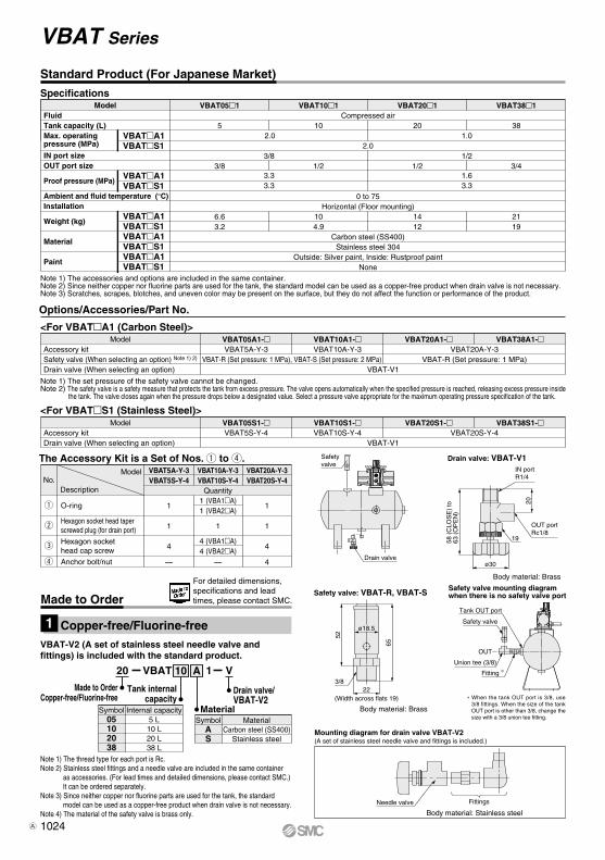
Standard Product (For Japanese Market)
Model VBAT20S1- VBAT38S1-<For VBATS1 (Stainless Steel)>
Accessory kitDrain valve (When selecting an option)
VBAT05S1-VBAT5S-Y-4
VBAT-V1
VBAT10S1-VBAT10S-Y-4 VBAT20S-Y-4
Model
DescriptionNo.
The Accessory Kit is a Set of Nos. q to r.
Anchor bolt/nutr
O-ring
Hexagon socket head cap screw
q
w
e
—
VBAT10A-Y-3VBAT10S-Y-4
—
VBAT20A-Y-3VBAT20S-Y-4
4
1
1
4
1 (VBA1A)1 (VBA2A)
1
4 (VBA1A)4 (VBA2A)
1
1
4
Quantity
Specifications
Note 1) The accessories and options are included in the same container.Note 2) Since neither copper nor fluorine parts are used for the tank, the standard model can be used as a copper-free product when drain valve is not necessary.Note 3) Scratches, scrapes, blotches, and uneven color may be present on the surface, but they do not affect the function or performance of the product.
Model VBAT20A1- VBAT38A1-<For VBATA1 (Carbon Steel)>
Accessory kitSafety valve (When selecting an option) Note 1) 2)
Drain valve (When selecting an option)
VBAT05A1-VBAT5A-Y-3
VBAT-R (Set pressure: 1 MPa), VBAT-S (Set pressure: 2 MPa)VBAT-V1
VBAT10A1-VBAT10A-Y-3 VBAT20A-Y-3
VBAT-R (Set pressure: 1 MPa)
Note 1) The set pressure of the safety valve cannot be changed.Note 2) The safety valve is a safety measure that protects the tank from excess pressure. The valve opens automatically when the specified pressure is reached, releasing excess pressure inside
the tank. The valve closes again when the pressure drops below a designated value. Select a pressure valve appropriate for the maximum operating pressure specification of the tank.
Copper-free/Fluorine-free1
20 1VBAT V
Made to OrderCopper-free/Fluorine-free
Made to Order
For detailed dimensions, specifications and lead times, please contact SMC.
MaterialCarbon steel (SS400)
Stainless steel
Material
Drain valve/VBAT-V2
SymbolAS
Internal capacity5 L10 L20 L38 L
Tank internalcapacity
Symbol05102038
A10
Hexagon socket head taper screwed plug (for drain port)
Body material: Brass
Body material: Brass
Model VBAT051 VBAT101 VBAT201 VBAT381FluidTank capacity (L)Max. operating pressure (MPa)
IN port sizeOUT port size
Proof pressure (MPa)
Ambient and fluid temperature (°C)Installation
Weight (kg)
Material
Paint
Compressed air
2.0
0 to 75Horizontal (Floor mounting)
Carbon steel (SS400)Stainless steel 304
Outside: Silver paint, Inside: Rustproof paintNone
5 10
3/8
3.33.3
3/8 1/2
6.6 103.2 4.9
20
1/21/2
1.63.3
1412
38
3/4
2119
VBATA1VBATS1
VBATA1VBATS1
VBATA1VBATS1VBATA1VBATS1VBATA1VBATS1
2.0 1.0
Options/Accessories/Part No.
VBAT5A-Y-3VBAT5S-Y-4
Note 1) The thread type for each port is Rc.Note 2) Stainless steel fittings and a needle valve are included in the same container
as accessories. (For lead times and detailed dimensions, please contact SMC.) It can be ordered separately.
Note 3) Since neither copper nor fluorine parts are used for the tank, the standard model can be used as a copper-free product when drain valve is not necessary.
Note 4) The material of the safety valve is brass only.
Mounting diagram for drain valve VBAT-V2
Safety valve mounting diagram when there is no safety valve port
Body material: Stainless steel
OUT
Tank OUT port
Safety valve
Union tee (3/8)
Fitting ∗
(A set of stainless steel needle valve and fittings is included.)
Needle valve Fittings
∗ When the tank OUT port is 3/8, use 3/8 fittings. When the size of the tank OUT port is other than 3/8, change the size with a 3/8 union tee fitting.
VBAT-V2 (A set of stainless steel needle valve and fittings) is included with the standard product.
1024A
Booster regulator IN portRc 3/8
120180
(454
)
(367
)
OUT
4 x ø11
EXH: Rc 3/8
Tank OUT portRc 1/2
Drain portRc 1/4
278
170
312
60
460
471∗
3232
ø180
Booster regulator IN portRc 1/4
OUT
Tank OUT portRc 3/8
Tank OUT portRc 1/2
200
163
170
278
(391
)
(328
)
257
338
349∗
60
60
32
32
32
32
Drain portRc 1/4
Drain portRc 1/4
312460
471∗
The plug cannot be removed.
The plug cannot be removed.
The plug cannot be removed.
The plug cannot be removed.
EXH: Rc 1/4
4 x ø11
120
180
ø180
C
100
200
(A)
(B)
OUT
4 x ø13
EXH: C
Tank OUT portRc 1/2
Drain portRc 1/4
305
180
5050
685∗
400
674
ø206
442
(417
)
ø180
(367
)
180120
EXH: Rc 3/8
4 x ø11
Booster regulator IN portRc 3/8
OUT
(A) D
(B)
ø206
200100
EXH: C
OUT
Booster regulator IN portC
4 x ø13
Tank IN portRc 3/8
Tank IN portRc 3/8
Tank IN portRc 3/8
Tank IN portRc 1/2
Booster regulator IN portRc 1/4
OUT
(307
)
(370
)
EXH: Rc 1/4
4 x ø11
100160
ø156
Booster regulator IN port
Connected to VBA20A
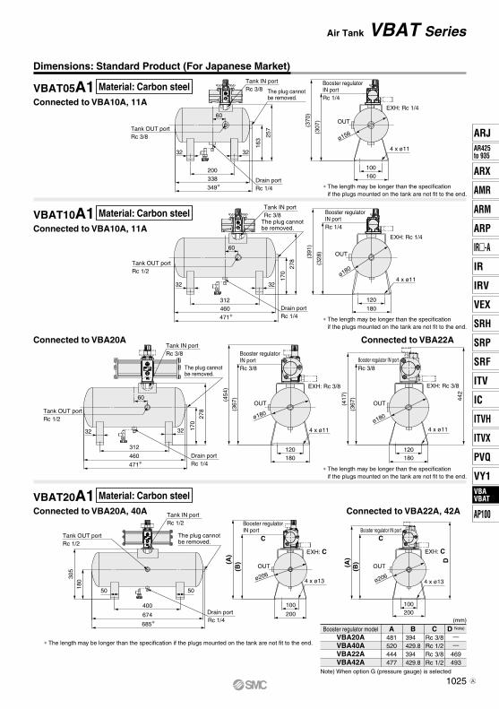
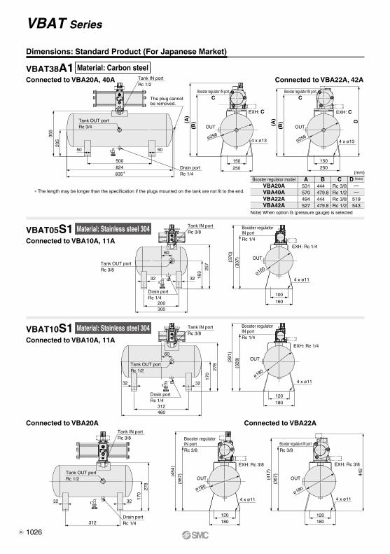
Dimensions: Standard Product (For Japanese Market)
∗ The length may be longer than the specification if the plugs mounted on the tank are not fit to the end.
∗ The length may be longer than the specification if the plugs mounted on the tank are not fit to the end.
∗ The length may be longer than the specification if the plugs mounted on the tank are not fit to the end.
Connected to VBA22A
Connected to VBA22A, 42A
Note) When option G (pressure gauge) is selected
(mm)
D Note)
——
469493
B394 429.8394 429.8
CRc 3/8Rc 1/2Rc 3/8Rc 1/2
A481520444477
VBA20AVBA40AVBA22AVBA42A
Booster regulator model
∗ The length may be longer than the specification if the plugs mounted on the tank are not fit to the end.
Connected to VBA10A, 11AVBAT05A1 Material: Carbon steel
Material: Carbon steel
Material: Carbon steel
Connected to VBA10A, 11AVBAT10A1
Connected to VBA20A, 40AVBAT20A1
Air Tank VBAT Series
1025
ARJAR425to 935
ARX
AMR
ARM
ARP
IR-A
IR
IRV
VEX
SRH
SRP
SRF
ITV
IC
ITVX
ITVH
PVQ
VY1VBAVBAT
AP100
VBAVBAT
A
Booster regulator IN portRc 1/4
Booster regulator IN portRc 1/4
EXH: Rc 1/4
EXH: Rc 1/4
OUT
OUT
100
120
180
160
4 x ø11
4 x ø11
ø160
ø180
Tank OUT portRc 3/8
60
60
200
312460
170
278 (328
)
257
163
(370
)(3
91)
(307
)
300
32
32
32
32
Drain portRc 1/4
Drain portRc 1/4
Tank IN portRc 3/8
Tank IN portRc 3/8
Booster regulator IN portC
150
250
(A)
(B)
OUT
4 x ø13
EXH: C
Tank OUT portRc 3/4
Drain portRc 1/4
355
205
500
5050
824835∗
ø256ø256
(A)
(B) D
250
150
Booster regulator IN portC
OUT
EXH: C
4 x ø13
Tank IN portRc 1/2
Booster regulator IN portRc 3/8
120180
(454
)
(367
)
OUT
4 x ø11
EXH: Rc 3/8
Tank OUT portRc 1/2
Drain portRc 1/4
278
170
312
3232
ø180
442
(417
)
ø180
(367
)
180120
EXH: Rc 3/8
4 x ø11
Booster regulator IN portRc 3/8
OUT
Tank IN portRc 3/8
Tank OUT portRc 1/2
The plug cannot be removed.
Connected to VBA10A, 11AVBAT10S1 Material: Stainless steel 304
Dimensions: Standard Product (For Japanese Market)
Connected to VBA22A, 42A
D Note)
——
519543
B444 479.8444 479.8
CRc 3/8Rc 1/2Rc 3/8Rc 1/2
A531570494527
VBA20AVBA40AVBA22AVBA42A
Booster regulator model
Note) When option G (pressure gauge) is selected
(mm)
∗ The length may be longer than the specification if the plugs mounted on the tank are not fit to the end.
Connected to VBA20A, 40AVBAT38A1
Connected to VBA10A, 11AVBAT05S1 Material: Stainless steel 304
Connected to VBA20A Connected to VBA22A
Material: Carbon steel
VBAT Series
1026A
C
100
200(A
)(B
) OUT
4 x ø13
EXH: C
Tank OUT portRc 1/2
Drain portRc 1/4
305
180
400
5050
674
ø206
D
(A)
ø206
(B)
200
100
EXH: C
OUT
Booster regulator IN portC
4 x ø13
Tank IN portRc 1/2
C
150
250
(A)
(B)
OUT
4 x ø13
EXH: C
Tank OUT portRc 3/4
Drain portRc 1/4
355
205
500
5050
824
ø256
D(A)
ø256
(B)
250
150
Booster regulator IN portC
OUT
EXH: C
4 x ø13
Tank IN portRc 1/2
250
A
Booster regulator IN port
Booster regulator IN port
Safety valve portRc 3/8
Safety valve portRc 3/8
Dimensions: Standard Product (For Japanese Market)
Connected to VBA22A, 42A
D Note)
——
469493—
B394 429.8394 429.8429.8
CRc 3/8Rc 1/2Rc 3/8Rc 1/2Rc 1/2
A481520444477526
VBA20AVBA40AVBA22AVBA42AVBA43A
Booster regulator model
Note) When option G (pressure gauge) is selected
(mm)
Connected to VBA20A, 40A, 43AVBAT20S1
VBAT38S1Connected to VBA20A, 40A, 43A
VBAT A1-With safety valve
Connected to VBA22A, 42A
D Note)
——
519543—
B444 479.8444 479.8479.8
CRc 3/8Rc 1/2Rc 3/8Rc 1/2Rc 1/2
A531570494527576
VBA20AVBA40AVBA22AVBA42AVBA43A
Booster regulator model
Note) When option G (pressure gauge) is selected
(mm)
A 60130
VBAT05VBAT10
Tank model(mm)
0510
RS VBAT A1-
With safety valve
2038
RS
Material: Stainless steel 304
Material: Stainless steel 304
Air Tank VBAT Series
1027
ARJAR425to 935
ARX
AMR
ARM
ARP
IR-A
IR
IRV
VEX
SRH
SRP
SRF
ITV
IC
ITVX
ITVH
PVQ
VY1VBAVBAT
AP100
VBAVBAT
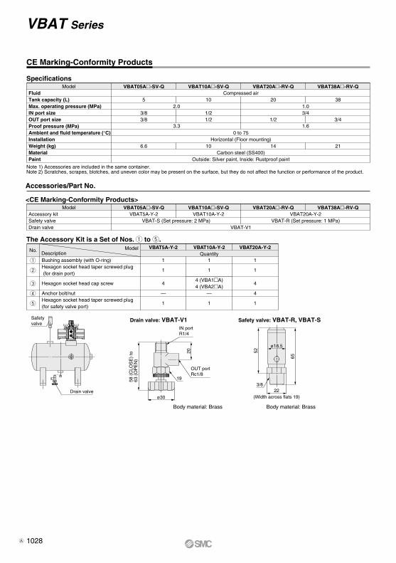
VBAT Series
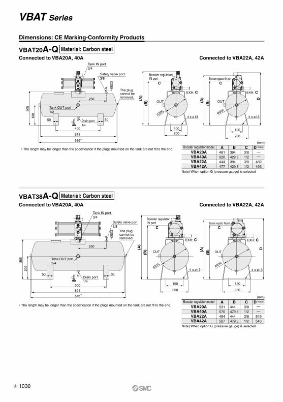
CE Marking-Conformity Products
Model VBAT05A-SV-Q VBAT10A-SV-Q VBAT20A-RV-Q VBAT38A-RV-Q
52.0
Outside: Silver paint, Inside: Rustproof paint
10 20 38
3/8 1/2 3/43/8 1/2 1/2 3/4
6.6 10 14 21
Compressed air
0 to 75Horizontal (Floor mounting)
Carbon steel (SS400)
1.0
3.3 1.6
FluidTank capacity (L)Max. operating pressure (MPa)IN port sizeOUT port sizeProof pressure (MPa)Ambient and fluid temperature (°C)InstallationWeight (kg)MaterialPaint
Note 1) Accessories are included in the same container.Note 2) Scratches, scrapes, blotches, and uneven color may be present on the surface, but they do not affect the function or performance of the product.
Drain valve
Safetyvalve
IN portR1/4
19
OUT portRc1/8
20
ø30
58 (
CLO
SE
) to
63
(O
PE
N)
Safety valve: VBAT-R, VBAT-SDrain valve: VBAT-V1
52
65
3/822
(Width across flats 19)
ø18.5
Model VBAT05A-SV-Q VBAT10A-SV-Q VBAT20A-RV-Q VBAT38A-RV-Q<CE Marking-Conformity Products>
Accessory kitSafety valveDrain valve
VBAT5A-Y-2VBAT-S (Set pressure: 2 MPa)
VBAT-V1
VBAT10A-Y-2 VBAT20A-Y-2VBAT-R (Set pressure: 1 MPa)
The Accessory Kit is a Set of Nos. q to t.
Accessories/Part No.
Body material: Brass Body material: Brass
ModelDescription
No. VBAT5A-Y-2
Bushing assembly (with O-ring)Hexagon socket head taper screwed plug (for drain port)
Hexagon socket head cap screw
Anchor bolt/nutHexagon socket head taper screwed plug (for safety valve port)
q
w
e
r
t
1
1
4
—
1
VBAT10A-Y-2
1
1
4 (VBA1A)4 (VBA2A)
—
1
VBAT20A-Y-2
1
1
4
4
1
Quantity
Specifications
1028A
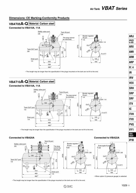
∗ When option G (pressure gauge) is selected
Safety valve port
130 60
3232
312 120
180460
482∗
3/8 Booster regulator IN port
OUT
3/8
Tank IN port1/2
Tank OUT port1/2
The plug cannot be removed.
278
(417
)
(367
) 442∗
170
Drain port1/4
EXH: 3/8
4 x ø11ø180
(367
)(454
)
Booster regulator IN port3/8
OUT
EXH: 3/8
ø180
4 x ø11
120
180
Booster regulator IN port1/4
(307
)
257
163
(370
)
EXH: 1/4
OUT
4 x ø11
100
160
ø156
Safety valve port3/8
60
32
200
338
360∗
32
60
Tank IN port3/8
The plug cannot be removed.
Tank OUT port3/8
Drain port1/4
(328
)
170
278 (3
91)
EXH: 1/4
Booster regulator IN port1/4
OUT130
32 32
312
460
482∗
60
4 x ø11
120
180
ø180
∗ The length may be longer than the specification if the plugs mounted on the tank are not fit to the end.
∗ The length may be longer than the specification if the plugs mounted on the tank are not fit to the end.
∗ The length may be longer than the specification if the plugs mounted on the tank are not fit to the end.
Safety valve port3/8 Tank IN port
1/2
Tank OUT port1/2
Drain port1/4
The plug cannot be removed.
VBAT05A-Q
VBAT10A-Q
Dimensions: CE Marking-Conformity Products
Connected to VBA10A, 11A
Connected to VBA10A, 11A
Connected to VBA20A Connected to VBA22A
Material: Carbon steel
Material: Carbon steel
Air Tank VBAT Series
1029
ARJAR425to 935
ARX
AMR
ARM
ARP
IR-A
IR
IRV
VEX
SRH
SRP
SRF
ITV
IC
ITVX
ITVH
PVQ
VY1VBAVBAT
AP100
VBAVBAT
A
(A)
(A)
(B)
(B)
Tank OUT port1/2
Tank IN port3/4
Safety valve port3/8
The plug cannot be removed.
Drain port1/4
50
400
250OUT
50
674
696∗
CBooster regulator IN port
C
D
EXH: C EXH: C
305
180
OUT
ø206
4 x ø13
100200
100
200
∗ The length may be longer than the specification if the plugs mounted on the tank are not fit to the end. D Note)
——
469493
B394 429.8394 429.8
C3/81/23/81/2
A481520444477
VBA20AVBA40AVBA22AVBA42A
Booster regulator model
Note) When option G (pressure gauge) is selected
(mm)
D Note)
——
519543
B444 479.8444 479.8
C3/81/23/81/2
A531570494527
VBA20AVBA40AVBA22AVBA42A
Booster regulator model
Note) When option G (pressure gauge) is selected
(mm)
(A)
(B)
OUT
ø256
4 x ø13ø256
4 x ø13
ø206
4 x ø13
EXH: C
150
250
C
(A)
(B)
Tank OUT port3/4
Tank IN port3/4
Safety valve port3/8
The plug cannot be removed.
Drain port1/4
50
500
250
OUT
50
824
846∗
Booster regulator IN port
C
D
EXH: C
355
205
150
250
∗ The length may be longer than the specification if the plugs mounted on the tank are not fit to the end.
Booster regulator IN port
Booster regulator IN port
VBAT20A-Q
VBAT38A-Q
Connected to VBA20A, 40A
Connected to VBA20A, 40A
Connected to VBA22A, 42A
Connected to VBA22A, 42A
Dimensions: CE Marking-Conformity Products
Material: Carbon steel
Material: Carbon steel
VBAT Series
1030A

VBAT Series
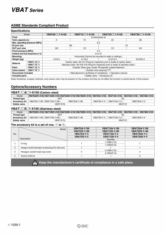
ASME Standards Compliant Product
Options/Accessory Numbers
Keep the manufacturer’s certificate of compliance in a safe place.
VBATA1-X105 (Carbon steel)Model VBAT05AN1-X105 VBAT10AN1-X105 VBAT20AN1-X105 VBAT38AN1-X105 VBAT05A1-X105 VBAT10A1-X105 VBAT20A1-X105 VBAT38A1-X105
Thread type NPT RcAccessory kit VBAT5A-Y-3N VBAT10A-Y-3N VBAT20A-Y-3N VBAT5A-Y-3 VBAT10A-Y-3 VBAT20A-Y-3Safety valve VBAT-E1N VBAT-E1
VBATS1-X105 (Stainless steel)Model VBAT05SN1-X105 VBAT10SN1-X105 VBAT20SN1-X105 VBAT38SN1-X105 VBAT05S1-X105 VBAT10S1-X105 VBAT20S1-X105 VBAT38S1-X105
Thread type NPT RcAccessory kit VBAT5S-Y-4N VBAT10S-Y-4N VBAT20S-Y-4N VBAT5S-Y-4 VBAT10S-Y-4 VBAT20S-Y-4Safety valve VBAT-E1N VBAT-E1
SpecificationsModel VBAT051-X105 VBAT101-X105 VBAT201-X105 VBAT381-X105
Fluid Compressed airTank capacity [L] 5 10 22 38Max. operating pressure [MPa] 2.0IN port size 3/8 1/2OUT port size 3/8 1/2 1/2 3/4Proof pressure [MPa] 2.2Ambient and fluid temperature [°C] 0 to 75Mounting Horizontal (Cannot be mounted to walls or ceilings.)Weight [kg] 4.5/3.2 9.1/8.2 15.0/13.2 20.9/20.4
MaterialVBATA1 Carbon steel SA-414 (Plug for inspection port is made of carbon steel.)VBATS1 Stainless steel SA-240 316 (Plug for inspection port is made of stainless steel.)
Paint VBATA1 Outside: Silver gray, Inside: Phosphate coated treatmentSurface treatment VBATS1 Outside: Acid cleaning Note)
Documents included • Manufacturer’s certificate of compliance • Operation manualIncluded parts • Safety valve • Accessory kit
Note) Scratches, scrapes, blotches, and uneven color may be present on the surface, but they do not affect the function or performance of the product.
The accessory kit is a set of nos. q to r.
No.
Model
Description
VBAT5A-Y-3N VBAT10A-Y-3N VBAT20A-Y-3NVBAT5S-Y-4N VBAT10S-Y-4N VBAT20S-Y-4NVBAT5A-Y-3 VBAT10A-Y-3 VBAT20A-Y-3VBAT5S-Y-4 VBAT10S-Y-4 VBAT20S-Y-4
Quantity
q O-ring 11 (VBA1A)
11 (VBA2A)
w Hexagon socket head taper screwed plug (For drain port) 1 1 1
e Hexagon socket head cap screw 44 (VBA1A)
44 (VBA2A)
r Anchor bolt/nut — — 4
1030-1D
OUT
EXH: 1/4"
OUT
EXH: 1/4"
OUT
EXH: 3/8"
OUT
EXH: 3/8"
EXH: 1/4"
OUT
Connected to VBA22A
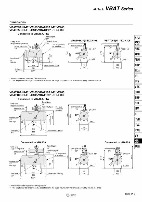
VBAT05A(N)1-E-X105 VBAT05S(N)1-E-X105
Safety valve port1/4"
Safety valve(Supplied with product)
Tank IN port3/8"
Tank OUT port3/8"
The plug cannot be removed.
257
163
60Inspection port3/4"(With plug)
Drain port1/4" 374∗1
352
200 Drain valve (Option)160
100
160
100
4 x ø11
(370
)
(307
)
4 x ø11
(370
)
(307
)
Booster regulator IN port1/4"
Booster regulator IN port1/4"
ø150ø14
8
Safety valve port1/4"
Safety valve(Supplied with product)
Inspection port3/4"(With plug)
Tank IN port3/8"
Tank OUT port1/2"
278
170
The plug cannot be removed.
60
3232
(391
)
(328
)
180
120
4 x ø11
Booster regulator IN port1/4"
ø170
Safety valve port1/4"
Safety valve(Supplied with product)
Tank IN port3/8"
Tank OUT port1/2" The plug cannot
be removed.
Inspection port3/4"(With plug) 3232
278
170
180
120
180
120
4 x ø11 4 x ø11
(417
)
(367
)
(454
)
(367
)
(442
)
Booster regulator IN port3/8"
Booster regulator IN port3/8"
ø170ø170
60
Connected to VBA20A
Connected to VBA10A, 11A
Connected to VBA10A, 11A
3232
Drain port1/4"
312Drain valve (Option)
Drain port1/4"
Drain valve (Option)312
498
522∗1
498
522∗1
Air Tank VBAT Series
VBAT05AN1-E-X105/VBAT05A1-E-X105VBAT05SN1-E-X105/VBAT05S1-E-X105
VBAT10AN1-E-X105/VBAT10A1-E-X105VBAT10SN1-E-X105/VBAT10S1-E-X105
Dimensions
* Order the booster regulator VBA separately.*1 The length may be longer than the specification if the plugs mounted on the tank are not tightly fitted to the ends.
* Order the booster regulator VBA separately.*1 The length may be longer than the specification if the plugs mounted on the tank are not tightly fitted to the ends.
1030-2
ARJAR425to 935
ARX
AMR
ARM
ARP
IR-A
IR
IRV
VEX
SRH
SRP
SRF
ITV
IC
ITVX
ITVH
PVQ
VY1VBAVBAT
AP100
VBAVBAT
C
EXH: C
OUTOUT
EXH: C
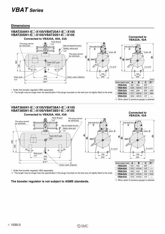
Connected toVBA22A, 42A
Connected toVBA22A, 42A
EXH: C
OUT
EXH: C
OUT
The plug cannot be removed.
180
305
50 50
Tank OUT port1/2"
The plug cannot be removed.
Safety valve port1/4"
Safety valve (Supplied with product)
Tank IN port1/2"
(B)(A
)
Booster regulator IN portC
ø216ø216
4 x ø13
200100
(B)(A
)
Booster regulator IN portC
200100
4 x ø13
(D)
The plug cannot be removed.
205
355
Tank IN port1/2"
Tank OUT port3/4"
The plug cannot be removed.
Safety valve port1/4"
Safety valve (Supplied with product)
5050
(B)(A
)
Booster regulator IN portC
(A)
( B)
Booster regulator IN portC
250150
250150
4 x ø13 4 x ø13
(D)
ø250ø250
Connected to VBA20A, 40A, 43A
Connected to VBA20A, 40A, 43A
Drain valve (Option)Drain port1/4"
700∗1
678400
Drain valve (Option)
Drain port1/4"
873∗1
851500
VBAT Series
The booster regulator is not subject to ASME standards.
VBAT20AN1-E-X105/VBAT20A1-E-X105VBAT20SN1-E-X105/VBAT20S1-E-X105
VBAT38AN1-E-X105/VBAT38A1-E-X105VBAT38SN1-E-X105/VBAT38S1-E-X105
Dimensions
Booster regulator model A B C D*1
VBA20A 481 394 3/8" —VBA40A 520 429.8 1/2" —VBA22A 444 394 3/8" 469VBA42A 477 429.8 1/2" 493VBA43A 526 429.8 1/2" —
Booster regulator model A B C D*1
VBA20A 531 444 3/8" —VBA40A 570 479.8 1/2" —VBA22A 494 444 3/8" 519VBA42A 527 479.8 1/2" 543VBA43A 576 479.8 1/2" —
* Order the booster regulator VBA separately.*1 The length may be longer than the specification if the plugs mounted on the tank are not tightly fitted to the ends.
* Order the booster regulator VBA separately.*1 The length may be longer than the specification if the plugs mounted on the tank are not tightly fitted to the ends.
*1 When option G (pressure gauge) is selected
[mm]
[mm]
*1 When option G (pressure gauge) is selected
1030-3C
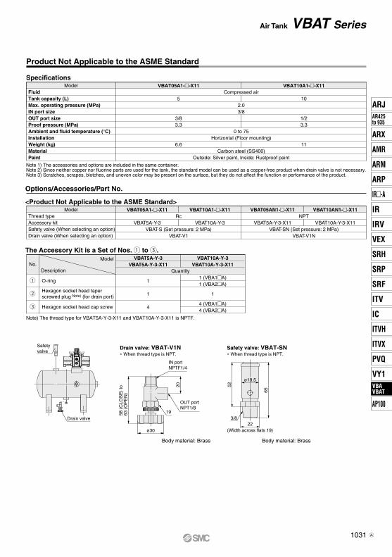
Air Tank VBAT Series
Drain valve
Safety valve
IN portNPTF1/4
19
OUT portNPT1/8
20
ø30
58 (
CLO
SE
) to
63 (
OP
EN
)
Safety valve: VBAT-SNDrain valve: VBAT-V1N
52
65
3/822
(Width across flats 19)
ø18.5
Product Not Applicable to the ASME Standard
Model
DescriptionNo.
The Accessory Kit is a Set of Nos. q to e.
O-ring
Hexagon socket head cap screw
q
w
e
VBAT5A-Y-3VBAT5A-Y-3-X11
1
1
4
VBAT10A-Y-3VBAT10A-Y-3-X11
1 (VBA1A)1 (VBA2A)
1
4 (VBA1A)4 (VBA2A)
Quantity
Model
Specifications
FluidTank capacity (L)Max. operating pressure (MPa)IN port sizeOUT port sizeProof pressure (MPa)Ambient and fluid temperature (°C)InstallationWeight (kg)MaterialPaint
Compressed air
2.0
0 to 75Horizontal (Floor mounting)
Carbon steel (SS400)Outside: Silver paint, Inside: Rustproof paint
3/8
VBAT05A1--X11
5
3/83.3 3.3
6.6
VBAT10A1--X11
10
1/2
11
Note 1) The accessories and options are included in the same container.Note 2) Since neither copper nor fluorine parts are used for the tank, the standard model can be used as a copper-free product when drain valve is not necessary.Note 3) Scratches, scrapes, blotches, and uneven color may be present on the surface, but they do not affect the function or performance of the product.
Hexagon socket head taperscrewed plug Note) (for drain port)
Body material: Brass Body material: Brass
Options/Accessories/Part No.
Note) The thread type for VBAT5A-Y-3-X11 and VBAT10A-Y-3-X11 is NPTF.
∗ When thread type is NPT. ∗ When thread type is NPT.
Model
<Product Not Applicable to the ASME Standard>
Thread typeAccessory kitSafety valve (When selecting an option)Drain valve (When selecting an option)
VBAT05A1--X11
VBAT5A-Y-3
VBAT10A1--X11
VBAT10A-Y-3Rc
VBAT-S (Set pressure: 2 MPa)VBAT-V1
VBAT10AN1--X11
VBAT10A-Y-3-X11
VBAT05AN1--X11
VBAT5A-Y-3-X11NPT
VBAT-SN (Set pressure: 2 MPa)VBAT-V1N
1031
ARJAR425to 935
ARX
AMR
ARM
ARP
IR-A
IR
IRV
VEX
SRH
SRP
SRF
ITV
IC
ITVX
ITVH
PVQ
VY1VBAVBAT
AP100
VBAVBAT
A
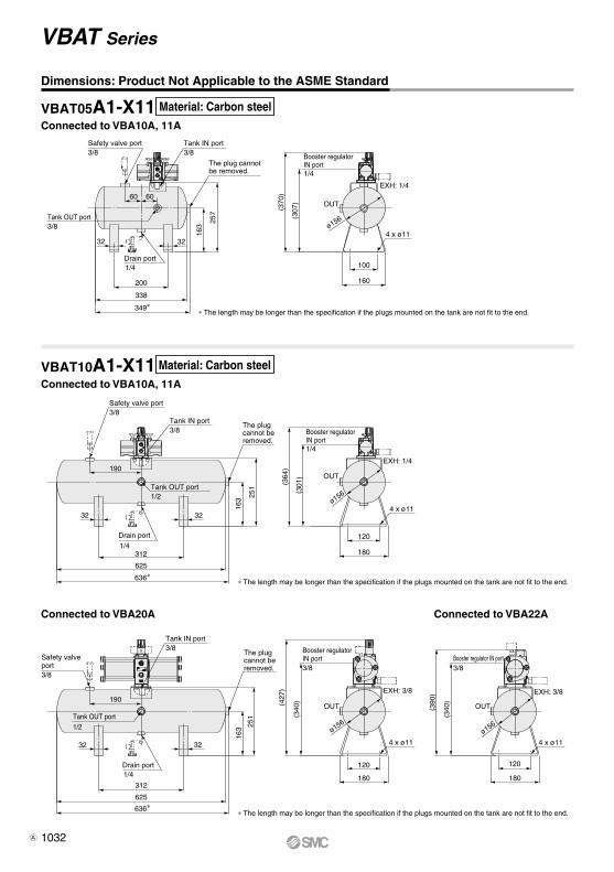
VBAT10A1-X11Connected to VBA10A, 11A
Connected to VBA20A Connected to VBA22A
Dimensions: Product Not Applicable to the ASME Standard
Material: Carbon steel
Material: Carbon steel
VBAT Series
Safety valve port3/8
Tank IN port3/8
Tank OUT port1/2
Tank OUT port1/2
Drain port1/4
Drain port1/4
The plug cannot be removed.
Safety valve port3/8
Tank IN port3/8
The plug cannot be removed.
190
32 32
ø156
ø156ø156
OUT
OUT OUT
Booster regulator IN port1/4
EXH: 1/4
Booster regulator IN port3/8
Booster regulator IN port3/8
EXH: 3/8 EXH: 3/8
4 x ø11
4 x ø11 4 x ø11
120
180312
625
636∗
312180
120
180
120
625
636∗
251 (301
)
(364
)
163
∗ The length may be longer than the specification if the plugs mounted on the tank are not fit to the end.
∗ The length may be longer than the specification if the plugs mounted on the tank are not fit to the end.
32
190
32
251
(427
)
(390
)
(340
)
(340
)
163
VBAT05A1-X11Connected to VBA10A, 11A
(307
)
∗ The length may be longer than the specification if the plugs mounted on the tank are not fit to the end.
Safety valve port3/8
6060
Tank IN port3/8
The plug cannot be removed.
257
163
32
Tank OUT port3/8
32
Drain port1/4
349∗338
200(3
70)
Booster regulator IN port1/4
OUT
ø156
EXH: 1/4
100
160
4 x ø11
1032A
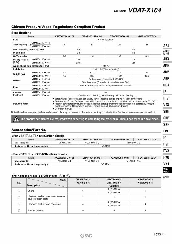
SpecificationsModel VBAT05m1-U-X104 VBAT10m1-U-X104 VBAT20m1-T-X104 VBAT38m1-T-X104
Fluid Compressed air
Tank capacity (L)VBATmA1-m-X104
5 10 22 38VBATmS1-m-X104
Max. operating pressure (MPa) 1.5 1.0
IN port size 3/8 1/2
OUT port size 3/8 1/2 1/2 3/4
Proof pressure (MPa)
VBATmA1-m-X104 2.39 2.05
VBATmS1-m-X104 2.40 1.58
Ambient and fluid temperature (°C) 0 to 75
Installation Horizontal (Floor mounting)
Weight (kg)VBATmA1-m-X104 6.6 11.5 14 26
VBATmS1-m-X104 4.6 8.5 13.9 19.6
MaterialVBATmA1-m-X104 Carbon steel (Equivalent to SS400)
VBATmS1-m-X104 Stainless steel (Equivalent to stainless steel 304)
PaintVBATmA1-m-X104 Outside: Silver gray, Inside: Phosphate coated treatment
VBATmS1-m-X104 —
Surface treatment
VBATmA1-m-X104 —
VBATmS1-m-X104 Outside: Acid cleaning, Sandblasting Insid: Acid cleaning
Included parts
¡�Safety valve/Pressure gauge set: Safety valve, Pressure gauge, Piping for tank connections¡�Accessories: O-ring, Drain port plug, VBA connection screw (4 pcs.), Anchor bolt/nut (4 pcs.: only 22 L/38 L)¡�Product certificates: Product certificate, Product safety performance supervision test certificate, Product
weight certificate, Manufacture license, Product manual, Completion drawing ¡Operation manual
Note) Scratches, scrapes, blotches, and uneven color may be present on the surface, but they do not affect the function or performance of the product.
<For VBATmS1-m-X104(Stainless Steel)>Model VBAT05S1-U-X104 VBAT10S1-U-X104 VBAT20S1-T-X104 VBAT38S1-T-X104
Accessory kit VBAT5S-Y-4 VBAT10S-Y-4 VBAT20S-Y-4Drain valve (Order it separately.) VBAT-V1
The Accessory Kit is a Set of Nos. q to r.
No.Model
Description
VBAT5A-Y-3 VBAT10A-Y-3 VBAT20A-Y-3VBAT5S-Y-4 VBAT10S-Y-4 VBAT20S-Y-4
Quantity
q O-ring 11 (VBA1mA)
11 (VBA2mA)
wHexagon socket head taper screwed plug (for drain port)
1 1 1
e Hexagon socket head cap screw 44 (VBA1mA)
44 (VBA2mA)
r Anchor bolt/nut — 4 4
The product certificates are required when exporting to and using the product in China. Keep them in a safe place.
<For VBATmA1-m-X104(Carbon Steel)>Model VBAT05A1-U-X104 VBAT10A1-U-X104 VBAT20A1-T-X104 VBAT38A1-T-X104
Accessory kit VBAT5A-Y-3 VBAT10A-Y-3 VBAT20A-Y-3
Drain valve (Order it separately.) VBAT-V1
Chinese Pressure Vessel Regulations Compliant Product
Accessories/Part No.
1033
Air Tank VBAT-X104
ARJAR425to 935
ARX
AMR
ARM
ARP
IR-A
IR
IRV
VEX
SRH
SRP
SRF
ITV
IC
ITVX
ITVH
PVQ
VY1VBAVBAT
AP100
VBAVBAT
E
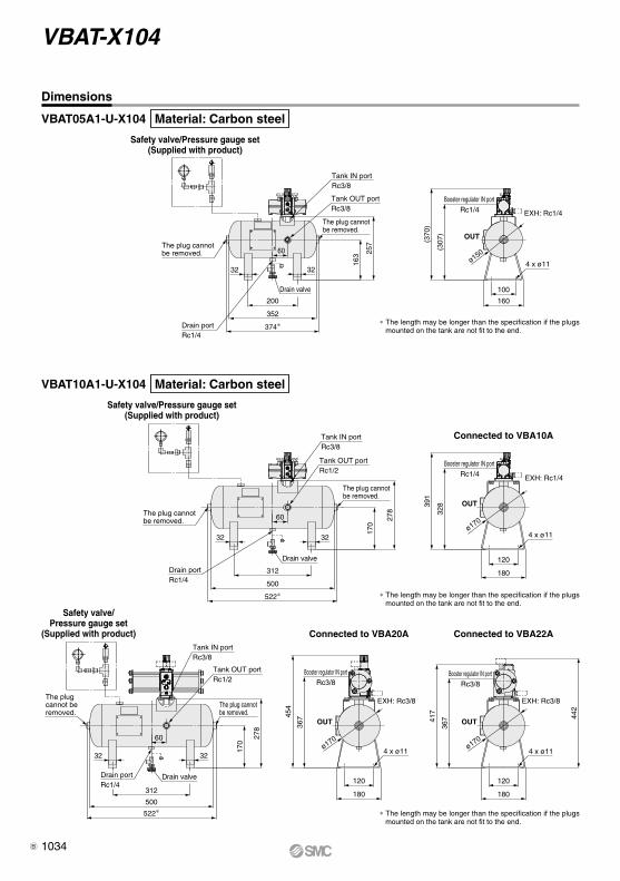
ø150
EXH: Rc1/4
Booster regulator IN portRc1/4
OUT
ø170
Booster regulator IN portRc1/4 EXH: Rc1/4
OUT
ø170ø170
OUT
Booster regulator IN portRc3/8
EXH: Rc3/8
Booster regulator IN portRc3/8
EXH: Rc3/8
OUT
Safety valve/Pressure gauge set(Supplied with product)
Safety valve/Pressure gauge set(Supplied with product)
Safety valve/Pressure gauge set
(Supplied with product)
Connected to VBA10A
Connected to VBA22AConnected to VBA20A
522∗500
312
Drain valve
32
Drain portRc1/4
32
Tank IN portRc3/8
Tank OUT portRc1/2
278
170
The plug cannot be removed.
The plug cannot be removed. 45
4
367
120
180
120
180
442
417
367
391
328
120
180
100
160
(307
)
(370
)
4 x ø11 4 x ø11
4 x ø11
4 x ø11
374∗352
200
Drain valve
Drain portRc1/4
32 32
60 257
163
Tank IN portRc3/8
The plug cannot be removed.
Tank OUT portRc3/8
The plug cannot be removed.
522∗500
312
Drain valve
32
Drain portRc1/4
32
Tank IN portRc3/8
Tank OUT portRc1/2
The plug cannot be removed.
278
170
The plug cannot be removed. 60
60
∗ The length may be longer than the specification if the plugs mounted on the tank are not fit to the end.
∗ The length may be longer than the specification if the plugs mounted on the tank are not fit to the end.
∗ The length may be longer than the specification if the plugs mounted on the tank are not fit to the end.
Dimensions
VBAT05A1-U-X104
VBAT10A1-U-X104
Material: Carbon steel
Material: Carbon steel
1034
VBAT-X104
B
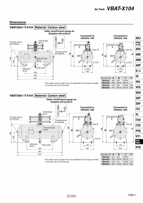
ø216ø216
OUTOUT
Booster regulator IN portC
EXH: C
Booster regulator IN portC
EXH: C
ø252ø252
OUTOUT
EXH: C
Booster regulator IN portC
EXH: C
Booster regulator IN portC
Safety valve/Pressure gauge set(Supplied with product)
Connected toVBA20A, 40A
Connected toVBA22A, 42A
Safety valve/Pressure gauge set(Supplied with product)
Connected toVBA20A, 40A
Connected toVBA22A, 42A
205
355
50 50
Drain valve
873∗851
500 250
150
250
150
DD
(B)(A
)
(B)( A
)
4 x ø13
700∗678
400
Drain valve
5050
180
305
Tank IN portRc1/2
(B)(A
)100
200
100
200
(B)(A
)
4 x ø13 4 x ø13
The plug cannot be removed.
The plug cannot be removed.
Tank OUT portRc3/4
Drain portRc1/4
Tank IN portRc1/2
The plug cannot be removed.
The plug cannot be removed.
Tank OUT portRc1/2
Drain portRc1/4
Dimensions
Booster regulator model A B C DVBA20A 481 394 Rc3/8 —VBA40A 520 429.8 Rc1/2 —VBA22A 444 394 Rc3/8 469VBA42A 477 429.8 Rc1/2 493
Booster regulator model A B C DVBA20A 531 444 Rc3/8 —VBA40A 570 479.8 Rc1/2 —VBA22A 494 444 Rc3/8 519VBA42A 527 479.8 Rc1/2 543
VBAT20A1-T-X104
VBAT38A1-T-X104
Material: Carbon steel
Material: Carbon steel
∗ The length may be longer than the specification if the plugs mounted on the tank are not fit to the end.
∗ The length may be longer than the specification if the plugs mounted on the tank are not fit to the end.
1035
Air Tank VBAT-X104
ARJAR425to 935
ARX
AMR
ARM
ARP
IR-A
IR
IRV
VEX
SRH
SRP
SRF
ITV
IC
ITVX
ITVH
PVQ
VY1VBAVBAT
AP100
VBAVBAT
B
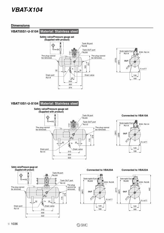
Connected to VBA10A
Safety valve/Pressure gauge set(Supplied with product)
Safety valve/Pressure gauge set(Supplied with product)
ø149
OUT
Rc1/4Booster regulator IN port
EXH: Rc1/4
Tank IN portRc3/8
Tank OUT portRc3/8
257
163
Drain portRc1/4
3232
Drain valve
(307
)
(370
)
160
100
4 x ø11
The plug cannot be removed.
The plug cannot be removed.
60
374
352
200
OUT
EXH: Rc1/4Rc1/4
Booster regulator IN port
ø170
Tank IN portRc3/8
Tank OUT portRc1/2
60
312Drain valveDrain port
Rc1/4
3232
278
170
(328
)
(391
)
180
120
4 x ø11
The plug cannot be removed.
The plug cannot be removed.
522
500
Rc3/8Booster regulator IN port
EXH: Rc3/8
OUT
Rc3/8EXH: Rc3/8
OUT
Booster regulator IN port
ø170ø17
0
Tank IN portRc3/8
Tank OUT portRc1/2
278
170
312
Drain valveDrain portRc1/4
The plug cannot be removed.
The plug cannot be removed.
3232
60
180
120
4 x ø11
(367
)(454
)
(367
)
(417
)
180
120
442
4 x ø11
Connected to VBA22AConnected to VBA20ASafety valve/Pressure gauge set
(Supplied with product)
522
500
Dimensions
VBAT05S1-U-X104
VBAT10S1-U-X104
Material: Stainless steel
Material: Stainless steel
1036
VBAT-X104
C
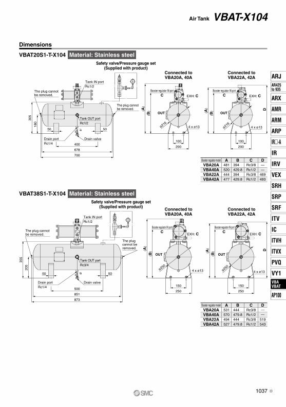
CBooster regulator IN port
OUT
EXH: C
OUT
CBooster regulator IN port
EXH: C
ø216ø216
Safety valve/Pressure gauge set(Supplied with product)
Connected toVBA20A, 40A
Connected toVBA22A, 42A
Tank IN portRc1/2
180
305
400
Drain valveDrain portRc1/4
Tank OUT portRc1/2
5050
(B)(A
)
4 x ø13
200
100
200
100
D
4 x ø13
(B)( A
)
The plug cannot be removed.
The plug cannot be removed.
700
678
CBooster regulator IN port
OUT
EXH: C
OUT
CBooster regulator IN port
EXH: C
ø250ø250
Safety valve/Pressure gauge set(Supplied with product) Connected to
VBA20A, 40AConnected toVBA22A, 42A
Tank IN portRc1/2
Drain valveDrain portRc1/4
Tank OUT portRc3/4
5050
(B)(A
)
4 x ø13
D
4 x ø13
(B)( A
)
The plug cannot be removed.
The plug cannot be removed.
250
150
250
150
873
851
500
355
205
Dimensions
Booster regulator model A B C DVBA20A 481 394 Rc3/8 —VBA40A 520 429.8 Rc1/2 —VBA22A 444 394 Rc3/8 469VBA42A 477 429.8 Rc1/2 493
Booster regulator model A B C DVBA20A 531 444 Rc3/8 ―VBA40A 570 479.8 Rc1/2 ―VBA22A 494 444 Rc3/8 519VBA42A 527 479.8 Rc1/2 543
VBAT20S1-T-X104
VBAT38S1-T-X104
Material: Stainless steel
Material: Stainless steel
1037
Air Tank VBAT-X104
ARJAR425to 935
ARX
AMR
ARM
ARP
IR-A
IR
IRV
VEX
SRH
SRP
SRF
ITV
IC
ITVX
ITVH
PVQ
VY1VBAVBAT
AP100
VBAVBAT
D
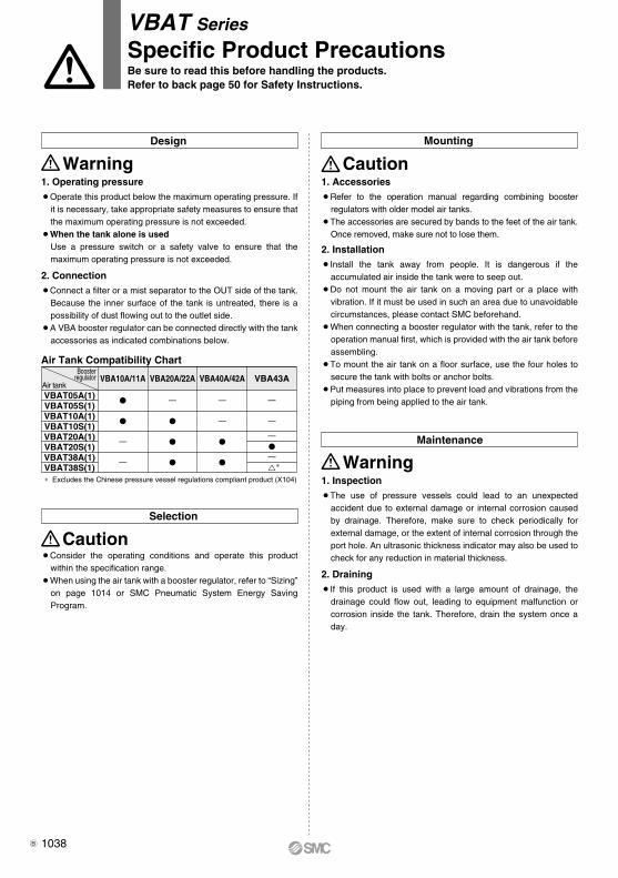
1. Operating pressure¡Operate this product below the maximum operating pressure. If
it is necessary, take appropriate safety measures to ensure that the maximum operating pressure is not exceeded.
¡When the tank alone is usedUse a pressure switch or a safety valve to ensure that the maximum operating pressure is not exceeded.
2. Connection¡Connect a filter or a mist separator to the OUT side of the tank.
Because the inner surface of the tank is untreated, there is a possibility of dust flowing out to the outlet side.
¡A VBA booster regulator can be connected directly with the tank accessories as indicated combinations below.
WarningDesign
1. Accessories¡Refer to the operation manual regarding combining booster
regulators with older model air tanks.¡The accessories are secured by bands to the feet of the air tank.
Once removed, make sure not to lose them.
2. Installation¡Install the tank away from people. It is dangerous if the
accumulated air inside the tank were to seep out.¡Do not mount the air tank on a moving part or a place with
vibration. If it must be used in such an area due to unavoidable circumstances, please contact SMC beforehand.
¡When connecting a booster regulator with the tank, refer to the operation manual first, which is provided with the air tank before assembling.
¡To mount the air tank on a floor surface, use the four holes to secure the tank with bolts or anchor bolts.
¡Put measures into place to prevent load and vibrations from the piping from being applied to the air tank.
Mounting
Caution
Selection
VBAT Series
Specific Product PrecautionsBe sure to read this before handling the products.Refer to back page 50 for Safety Instructions.
Maintenance
¡Consider the operating conditions and operate this product within the specification range.
¡When using the air tank with a booster regulator, refer to “Sizing” on page 1014 or SMC Pneumatic System Energy Saving Program.
Caution
1. Inspection¡The use of pressure vessels could lead to an unexpected
accident due to external damage or internal corrosion caused by drainage. Therefore, make sure to check periodically for external damage, or the extent of internal corrosion through the port hole. An ultrasonic thickness indicator may also be used to check for any reduction in material thickness.
2. Draining¡If this product is used with a large amount of drainage, the
drainage could flow out, leading to equipment malfunction or corrosion inside the tank. Therefore, drain the system once a day.
Warning
VBAT05A(1)VBAT05S(1)VBAT10A(1)VBAT10S(1)VBAT20A(1)VBAT20S(1)VBAT38A(1)VBAT38S(1)
VBA20A/22AVBA10A/11A VBA43A
—
—
—
VBA40A/42A
—
—
—
—
——∗
Air Tank Compatibility ChartBooster
regulatorAir tank
∗ Excludes the Chinese pressure vessel regulations compliant product (X104)
1038B