Embed Size (px)
Citation preview
1/4 Réf. GPAO 33522111701 Réf. Const. 5490 326 5000
BOOSTER 2000 UK
GENERATING SET USER AND
MAINTENANCE MANUAL
2/4 Réf. GPAO 33522111701 Réf. Const. 5490 326 5000
A
B
C
6
14
15
16
13
1211
9
10
8
51
7
6
432
3/4 Réf. GPAO 33522111701 Réf. Const. 5490 326 5000
D F
GE
4/4 Réf. GPAO 33522111701 Réf. Const. 5490 326 5000
H
I
J
3
1
2
1/12 Ref. GPAO : 33522111701 Ref. Const. 5490 326 5000
Contents
1. Introduction 2. General description 3. Preparation for operation 4. Using the generator set 5. Protective devices (if fitted, see specifications table) 6. Maintenance schedule
7. Maintenance procedures 8. Storing the generating set 9. Troubleshooting 10. Specifications 11. Cable sizes 12. Warranty conditions 13. E.C. Declaration of conformity
1. Introduction 1.1. Recommandations Thank you for buying one of our generating sets. We recommend that you read this manual carefully and follow the safety and maintenance advice and user instructions for your generating set very closely. The information contained in this manual is taken from technical data available at the time of print. In the intention of permanently improving the quality of our products, this information may be amended without warning. We are interested in your comments! This manual is updated regularly. We are interested in your comments and suggestions as they enable this document to be made increasingly more useful. You can contact us with any comments or suggestions at:
- fax: technical documentation department, number: + 00 33 (0)2 98 41 16 12 - by e-mail: [email protected]
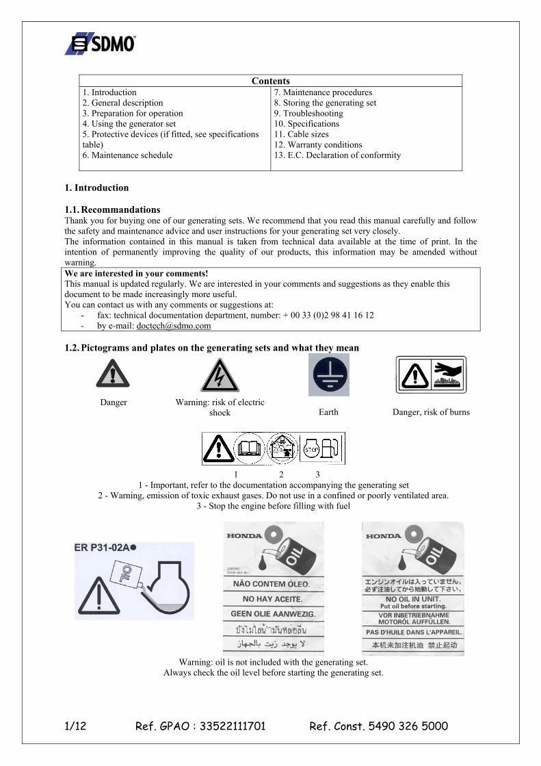
1.2. Pictograms and plates on the generating sets and what they mean
Danger
Warning: risk of electric
shock
Earth
Danger, risk of burns
1 2 3
1 - Important, refer to the documentation accompanying the generating set 2 - Warning, emission of toxic exhaust gases. Do not use in a confined or poorly ventilated area.
3 - Stop the engine before filling with fuel
Warning: oil is not included with the generating set.
Always check the oil level before starting the generating set.
2/12 Ref. GPAO : 33522111701 Ref. Const. 5490 326 5000
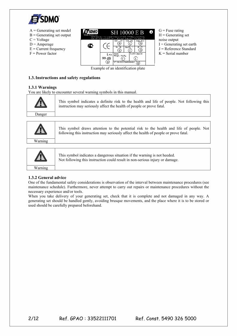
A = Generating set model B = Generating set output C = Voltage D = Amperage E = Current frequency F = Power factor
Example of an identification plate
G = Fuse rating H = Generating set noise output I = Generating set earth J = Reference Standard K = Serial number
1.3. Instructions and safety regulations 1.3.1 Warnings You are likely to encounter several warning symbols in this manual.
Danger
This symbol indicates a definite risk to the health and life of people. Not following this instruction may seriously affect the health of people or prove fatal.
Warning
This symbol draws attention to the potential risk to the health and life of people. Not following this instruction may seriously affect the health of people or prove fatal.
Warning
This symbol indicates a dangerous situation if the warning is not heeded. Not following this instruction could result in non-serious injury or damage.
1.3.2 General advice One of the fundamental safety considerations is observation of the interval between maintenance procedures (see maintenance schedule). Furthermore, never attempt to carry out repairs or maintenance procedures without the necessary experience and/or tools. When you take delivery of your generating set, check that it is complete and not damaged in any way. A generating set should be handled gently, avoiding brusque movements, and the place where it is to be stored or used should be carefully prepared beforehand.
3/12 Ref. GPAO : 33522111701 Ref. Const. 5490 326 5000
Warning
Before use, it is essential that you know how to stop the generating set immediately and that you thoroughly understand all the controls and operations.
Never let other people use the generating set without giving them all necessary instructions beforehand. Never let children touch the generating set, even when it is not in operation. Do not operate the generating set near animals (as it could cause them to panic). Never start the motor without an air filter or exhaust. Never invert the positive and negative battery terminals (if fitted) when connecting them. Such an inversion can lead to severe damage to the electrical equipment. Never cover the generating set with any type of material while it is in operation or just after it has been turned off. Wait until the motor is cold. Never coat the generating set with oil in an attempt to protect it from corrosion. Some preservative oils are flammable. Also, some are dangerous to inhale. In all cases, respect the local regulations currently in place concerning the use of generating sets. 1.3.3 Safeguards against electrocution
Danger
While they are in operation, generating sets produce electric current. Connect the generating set to earth each time you use it, in order to prevent electrocution.
Never touch stripped cables or disconnected connectors. Never handle a generating set with wet hands or feet. Never expose the equipment to liquid splashes or rainfall, and do not place it on wet ground. Always keep the electrical cables and the connections in good condition. Do not use equipment in a poor state of repair which could lead to electrocution or damage to the equipment. Use a differential protection device between the generating set and the appliances if the cable or cables used are more than 1 metre in length. Use flexible, durable cables, with rubber sheathing, conforming to the IEC 60245-4 standard or equivalent cables. Do not connect the generating set to other power sources, such as the mains. In specific cases where there is provision for a reserve connection to existing electrical networks, this must only be carried out by a qualified electrician, who should take the operating differences of the equipment into account, according to whether the mains or generating set is being used. Special circuit breakers designed for use with generating sets are used to prevent electrocution. If these circuit breakers need to be replaced, circuit breakers with identical nominal ratings and specifications must be used. 1.3.4 Safeguards against fire
Danger
Keep all inflammable materials (e.g.: petrol, oil, fabric etc.) out of the way when the generating set is in operation. The motor should not be operated in areas containing explosive products. There is a risk of sparks forming where all electrical and mechanical components are not shielded.
1.3.5 Safeguards against exhaust gases
Danger
Exhaust gases contain carbon monoxide, which is a highly toxic substance. This substance can cause death if it is present in excessive concentrations in the air inhaled. For this reason, always use the generating set in a well ventilated area, where gases will not be able to accumulate.
Good ventilation is required for your generating set to work properly. Without this, the motor would very quickly run at too high a temperature, which could lead to accidents or damage to the equipment and to surrounding items. However, if it is necessary to operate it inside a building, adequate ventilation must be provided, so that people and animals are not affected. It is imperative that exhaust gases are discharged outside.
4/12 Ref. GPAO : 33522111701 Ref. Const. 5490 326 5000
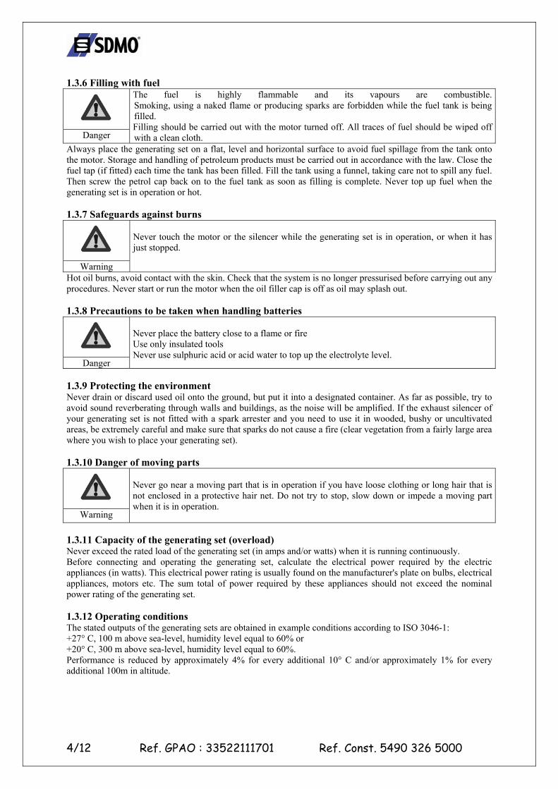
1.3.6 Filling with fuel
Danger
The fuel is highly flammable and its vapours are combustible. Smoking, using a naked flame or producing sparks are forbidden while the fuel tank is being filled. Filling should be carried out with the motor turned off. All traces of fuel should be wiped off with a clean cloth.
Always place the generating set on a flat, level and horizontal surface to avoid fuel spillage from the tank onto the motor. Storage and handling of petroleum products must be carried out in accordance with the law. Close the fuel tap (if fitted) each time the tank has been filled. Fill the tank using a funnel, taking care not to spill any fuel. Then screw the petrol cap back on to the fuel tank as soon as filling is complete. Never top up fuel when the generating set is in operation or hot. 1.3.7 Safeguards against burns
Warning
Never touch the motor or the silencer while the generating set is in operation, or when it has just stopped.
Hot oil burns, avoid contact with the skin. Check that the system is no longer pressurised before carrying out any procedures. Never start or run the motor when the oil filler cap is off as oil may splash out. 1.3.8 Precautions to be taken when handling batteries
Danger
Never place the battery close to a flame or fire Use only insulated tools Never use sulphuric acid or acid water to top up the electrolyte level.
1.3.9 Protecting the environment Never drain or discard used oil onto the ground, but put it into a designated container. As far as possible, try to avoid sound reverberating through walls and buildings, as the noise will be amplified. If the exhaust silencer of your generating set is not fitted with a spark arrester and you need to use it in wooded, bushy or uncultivated areas, be extremely careful and make sure that sparks do not cause a fire (clear vegetation from a fairly large area where you wish to place your generating set). 1.3.10 Danger of moving parts
Warning
Never go near a moving part that is in operation if you have loose clothing or long hair that is not enclosed in a protective hair net. Do not try to stop, slow down or impede a moving part when it is in operation.
1.3.11 Capacity of the generating set (overload) Never exceed the rated load of the generating set (in amps and/or watts) when it is running continuously. Before connecting and operating the generating set, calculate the electrical power required by the electric appliances (in watts). This electrical power rating is usually found on the manufacturer's plate on bulbs, electrical appliances, motors etc. The sum total of power required by these appliances should not exceed the nominal power rating of the generating set. 1.3.12 Operating conditions The stated outputs of the generating sets are obtained in example conditions according to ISO 3046-1: +27° C, 100 m above sea-level, humidity level equal to 60% or +20° C, 300 m above sea-level, humidity level equal to 60%. Performance is reduced by approximately 4% for every additional 10° C and/or approximately 1% for every additional 100m in altitude.
5/12 Ref. GPAO : 33522111701 Ref. Const. 5490 326 5000
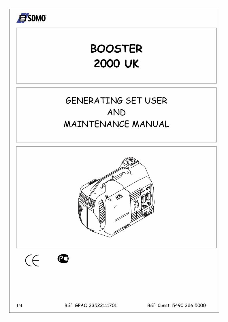
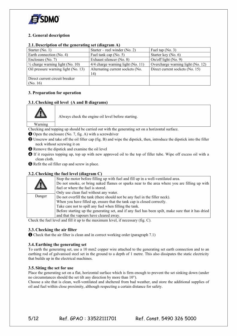
2. General description 2.1. Description of the generating set (diagram A) Starter (No. 1) Starter – reel winder (No. 2) Fuel tap (No. 3) Earth connection (No. 4) Fuel tank cap (No. 5) Starter key (No. 6) Enclosure (No. 7) Exhaust silencer (No. 8) On/off light (No. 9) ½ charge warning light (No. 10) 4/4 charge warning light (No. 11) Overcharge warning light (No. 12) Oil pressure warning light (No. 13) Alternating current sockets (No.
14) Direct current sockets (No. 15)
Direct current circuit breaker (No. 16)
3. Preparation for operation 3.1. Checking oil level (A and B diagrams)
Warning
Always check the engine oil level before starting.
Checking and topping up should be carried out with the generating set on a horizontal surface. ❶ Open the enclosure (No. 7, fig. A) with a screwdriver ❷ Unscrew and take off the oil filler cap (fig. B) and wipe the dipstick, then, introduce the dipstick into the filler
neck without screwing it on ❸ Remove the dipstick and examine the oil level ❹ If it requires topping up, top up with new approved oil to the top of filler tube. Wipe off excess oil with a
clean cloth. ❺ Refit the oil filler cap and screw in place. 3.2. Checking the fuel level (diagram C)
Danger
Stop the motor before filling up with fuel and fill up in a well-ventilated area. Do not smoke, or bring naked flames or sparks near to the area where you are filling up with fuel or where the fuel is stored. Only use clean fuel without any water. Do not overfill the tank (there should not be any fuel in the filler neck). When you have filled up, ensure that the tank cap is closed correctly. Take care not to spill any fuel when filling the tank. Before starting up the generating set, and if any fuel has been spilt, make sure that it has dried and that the vapours have cleared away.
Check the fuel level and fill it up to the maximum level, if necessary (fig. C). 3.3. Checking the air filter ❶ Check that the air filter is clean and in correct working order (paragraph 7.1) 3.4. Earthing the generating set To earth the generating set, use a 10 mm2 copper wire attached to the generating set earth connection and to an earthing rod of galvanised steel set in the ground to a depth of 1 metre. This also dissipates the static electricity that builds up in the electrical machines. 3.5. Siting the set for use Place the generating set on a flat, horizontal surface which is firm enough to prevent the set sinking down (under no circumstances should the set tilt any direction by more than 10°). Choose a site that is clean, well-ventilated and sheltered from bad weather, and store the additional supplies of oil and fuel within close proximity, although respecting a certain distance for safety.
6/12 Ref. GPAO : 33522111701 Ref. Const. 5490 326 5000
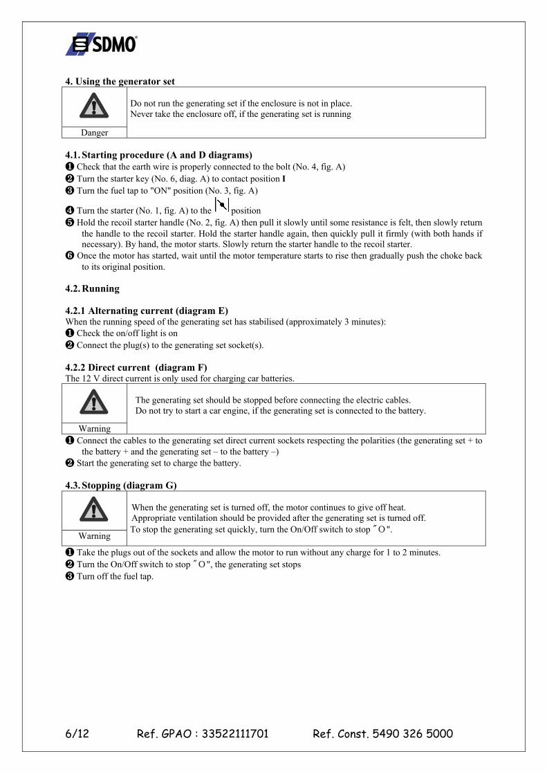
4. Using the generator set
Danger
Do not run the generating set if the enclosure is not in place. Never take the enclosure off, if the generating set is running
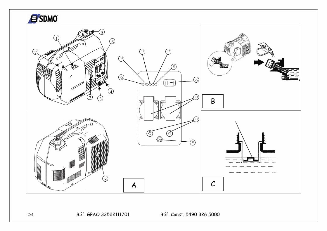
4.1. Starting procedure (A and D diagrams) ❶ Check that the earth wire is properly connected to the bolt (No. 4, fig. A) ❷ Turn the starter key (No. 6, diag. A) to contact position I ❸ Turn the fuel tap to "ON" position (No. 3, fig. A)
❹ Turn the starter (No. 1, fig. A) to the position ❺ Hold the recoil starter handle (No. 2, fig. A) then pull it slowly until some resistance is felt, then slowly return
the handle to the recoil starter. Hold the starter handle again, then quickly pull it firmly (with both hands if necessary). By hand, the motor starts. Slowly return the starter handle to the recoil starter.
❻ Once the motor has started, wait until the motor temperature starts to rise then gradually push the choke back to its original position.
4.2. Running 4.2.1 Alternating current (diagram E) When the running speed of the generating set has stabilised (approximately 3 minutes): ❶ Check the on/off light is on ❷ Connect the plug(s) to the generating set socket(s). 4.2.2 Direct current (diagram F) The 12 V direct current is only used for charging car batteries.
Warning
The generating set should be stopped before connecting the electric cables. Do not try to start a car engine, if the generating set is connected to the battery.
❶ Connect the cables to the generating set direct current sockets respecting the polarities (the generating set + to the battery + and the generating set – to the battery –)
❷ Start the generating set to charge the battery. 4.3. Stopping (diagram G)
Warning
When the generating set is turned off, the motor continues to give off heat. Appropriate ventilation should be provided after the generating set is turned off. To stop the generating set quickly, turn the On/Off switch to stop "О".
❶ Take the plugs out of the sockets and allow the motor to run without any charge for 1 to 2 minutes. ❷ Turn the On/Off switch to stop "О", the generating set stops ❸ Turn off the fuel tap.
7/12 Ref. GPAO : 33522111701 Ref. Const. 5490 326 5000
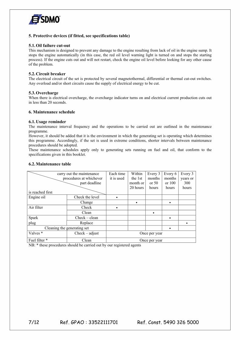
5. Protective devices (if fitted, see specifications table) 5.1. Oil failure cut-out This mechanism is designed to prevent any damage to the engine resulting from lack of oil in the engine sump. It stops the engine automatically (in this case, the red oil level warning light is turned on and stops the starting process). If the engine cuts out and will not restart, check the engine oil level before looking for any other cause of the problem. 5.2. Circuit breaker The electrical circuit of the set is protected by several magnetothermal, differential or thermal cut-out switches. Any overload and/or short circuits cause the supply of electrical energy to be cut. 5.3. Overcharge When there is electrical overcharge, the overcharge indicator turns on and electrical current production cuts out in less than 20 seconds. 6. Maintenance schedule 6.1. Usage reminder The maintenance interval frequency and the operations to be carried out are outlined in the maintenance programme. However, it should be added that it is the environment in which the generating set is operating which determines this programme. Accordingly, if the set is used in extreme conditions, shorter intervals between maintenance procedures should be adopted. These maintenance schedules apply only to generating sets running on fuel and oil, that conform to the specifications given in this booklet. 6.2. Maintenance table
carry out the maintenance procedures at whichever
part deadline is reached first
Each time it is used
Within the 1st
month or 20 hours
Every 3 months or 50 hours
Every 6 months or 100 hours
Every 3 years or
300 hours
Check the level • Engine oil Change • • Check • Air filter Clean •
Spark Check – clean • plug Replace •
Cleaning the generating set • Valves * Check – adjust Once per year
Fuel filter * Clean Once per year NB: * these procedures should be carried out by our registered agents
8/12 Ref. GPAO : 33522111701 Ref. Const. 5490 326 5000
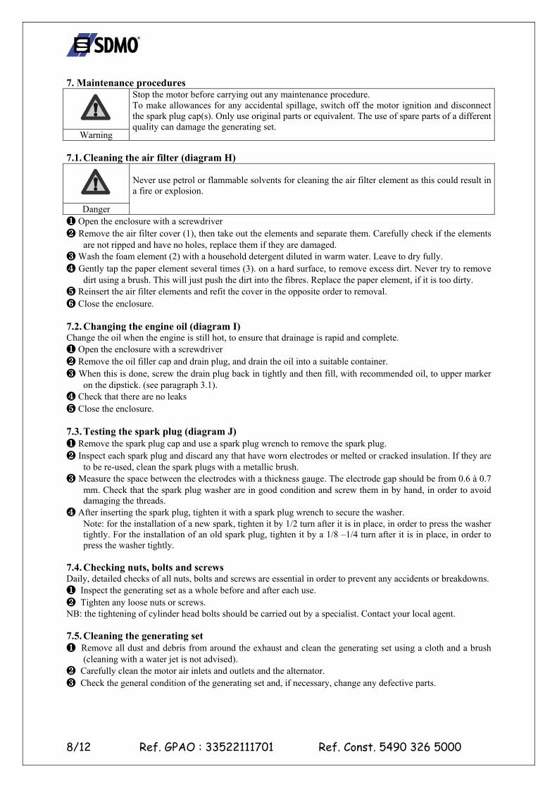
7. Maintenance procedures
Warning
Stop the motor before carrying out any maintenance procedure. To make allowances for any accidental spillage, switch off the motor ignition and disconnect the spark plug cap(s). Only use original parts or equivalent. The use of spare parts of a different quality can damage the generating set.
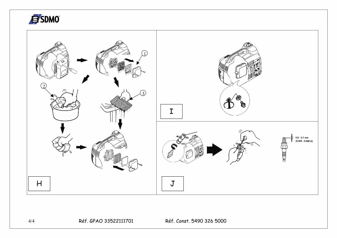
7.1. Cleaning the air filter (diagram H)
Danger
Never use petrol or flammable solvents for cleaning the air filter element as this could result in a fire or explosion.
❶ Open the enclosure with a screwdriver ❷ Remove the air filter cover (1), then take out the elements and separate them. Carefully check if the elements
are not ripped and have no holes, replace them if they are damaged. ❸ Wash the foam element (2) with a household detergent diluted in warm water. Leave to dry fully. ❹ Gently tap the paper element several times (3). on a hard surface, to remove excess dirt. Never try to remove
dirt using a brush. This will just push the dirt into the fibres. Replace the paper element, if it is too dirty. ❺ Reinsert the air filter elements and refit the cover in the opposite order to removal. ❻ Close the enclosure. 7.2. Changing the engine oil (diagram I) Change the oil when the engine is still hot, to ensure that drainage is rapid and complete. ❶ Open the enclosure with a screwdriver ❷ Remove the oil filler cap and drain plug, and drain the oil into a suitable container. ❸ When this is done, screw the drain plug back in tightly and then fill, with recommended oil, to upper marker
on the dipstick. (see paragraph 3.1). ❹ Check that there are no leaks ❺ Close the enclosure. 7.3. Testing the spark plug (diagram J) ❶ Remove the spark plug cap and use a spark plug wrench to remove the spark plug. ❷ Inspect each spark plug and discard any that have worn electrodes or melted or cracked insulation. If they are
to be re-used, clean the spark plugs with a metallic brush. ❸ Measure the space between the electrodes with a thickness gauge. The electrode gap should be from 0.6 à 0.7
mm. Check that the spark plug washer are in good condition and screw them in by hand, in order to avoid damaging the threads.
❹ After inserting the spark plug, tighten it with a spark plug wrench to secure the washer. Note: for the installation of a new spark, tighten it by 1/2 turn after it is in place, in order to press the washer tightly. For the installation of an old spark plug, tighten it by a 1/8 –1/4 turn after it is in place, in order to press the washer tightly.
7.4. Checking nuts, bolts and screws Daily, detailed checks of all nuts, bolts and screws are essential in order to prevent any accidents or breakdowns. ❶ Inspect the generating set as a whole before and after each use. ❷ Tighten any loose nuts or screws. NB: the tightening of cylinder head bolts should be carried out by a specialist. Contact your local agent. 7.5. Cleaning the generating set ❶ Remove all dust and debris from around the exhaust and clean the generating set using a cloth and a brush
(cleaning with a water jet is not advised). ❷ Carefully clean the motor air inlets and outlets and the alternator. ❸ Check the general condition of the generating set and, if necessary, change any defective parts.
9/12 Ref. GPAO : 33522111701 Ref. Const. 5490 326 5000
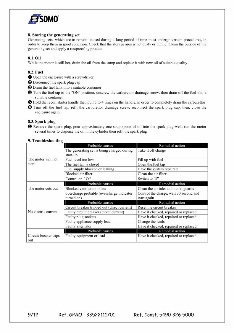
8. Storing the generating set Generating sets, which are to remain unused during a long period of time must undergo certain procedures, in order to keep them in good condition. Check that the storage area is not dusty or humid. Clean the outside of the generating set and apply a rustproofing product 8.1. Oil While the motor is still hot, drain the oil from the sump and replace it with new oil of suitable quality. 8.2. Fuel ❶ Open the enclosure with a screwdriver ❷ Disconnect the spark plug cap ❸ Drain the fuel tank into a suitable container ❹ Turn the fuel tap to the "ON" position, unscrew the carburettor drainage screw, then drain off the fuel into a
suitable container ❺ Hold the recoil starter handle then pull 3 to 4 times on the handle, in order to completely drain the carburettor ❻ Turn off the fuel tap, refit the carburettor drainage screw, reconnect the spark plug cap, then, close the
enclosure again. 8.3. Spark plug ❶ Remove the spark plug, pour approximately one soup spoon of oil into the spark plug well, run the motor
several times to disperse the oil in the cylinder then refit the spark plug 9. Troubleshooting
Probable causes Remedial action The generating set is being charged during start-up
Take it off charge
Fuel level too low Fill up with fuel The fuel tap is closed Open the fuel tap Fuel supply blocked or leaking Have the system repaired Blocked air filter Clean the air filter
The motor will not start
Control on "О" Switch to "I" Probable causes Remedial action
Blocked ventilation inlets Clean the air inlet and outlet guards The motor cuts out overcharge probable (overcharge indicator
turned on) Control the charge, wait 30 second and start again
Probable causes Remedial action Circuit breaker tripped out (direct current) Reset the circuit breaker Faulty circuit breaker (direct current) Have it checked, repaired or replaced Faulty plug sockets Have it checked, repaired or replaced Faulty appliance supply lead Change the leads
No electric current
Faulty alternator Have it checked, repaired or replaced Probable causes Remedial action
Circuit breaker trips out
Faulty equipment or lead Have it checked, repaired or replaced
10/12 Ref. GPAO : 33522111701 Ref. Const. 5490 326 5000
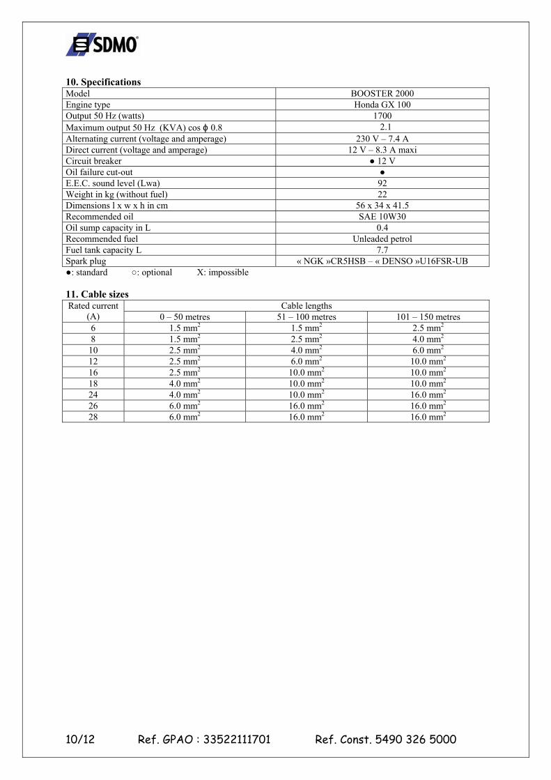
10. Specifications Model BOOSTER 2000 Engine type Honda GX 100 Output 50 Hz (watts) 1700 Maximum output 50 Hz (KVA) cos ϕ 0.8 2.1 Alternating current (voltage and amperage) 230 V – 7.4 A Direct current (voltage and amperage) 12 V – 8.3 A maxi Circuit breaker ● 12 V Oil failure cut-out ● E.E.C. sound level (Lwa) 92 Weight in kg (without fuel) 22 Dimensions l x w x h in cm 56 x 34 x 41.5 Recommended oil SAE 10W30 Oil sump capacity in L 0.4 Recommended fuel Unleaded petrol Fuel tank capacity L 7.7 Spark plug « NGK »CR5HSB – « DENSO »U16FSR-UB ●: standard ○: optional X: impossible 11. Cable sizes
Cable lengths Rated current (A) 0 – 50 metres 51 – 100 metres 101 – 150 metres 6 1.5 mm2 1.5 mm2 2.5 mm2 8 1.5 mm2 2.5 mm2 4.0 mm2
10 2.5 mm2 4.0 mm2 6.0 mm2 12 2.5 mm2 6.0 mm2 10.0 mm2 16 2.5 mm2 10.0 mm2 10.0 mm2 18 4.0 mm2 10.0 mm2 10.0 mm2 24 4.0 mm2 10.0 mm2 16.0 mm2 26 6.0 mm2 16.0 mm2 16.0 mm2 28 6.0 mm2 16.0 mm2 16.0 mm2
11/12 Ref. GPAO : 33522111701 Ref. Const. 5490 326 5000
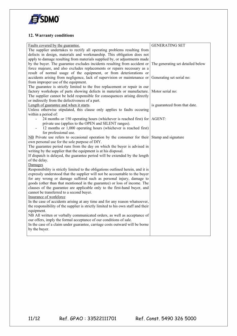
12. Warranty conditions Faults covered by the guarantee. The supplier undertakes to rectify all operating problems resulting from defects in design, materials and workmanship. This obligation does not apply to damage resulting from materials supplied by, or adjustments made by the buyer. The guarantee excludes incidents resulting from accident or force majeure, and also excludes replacements or repairs necessary as a result of normal usage of the equipment, or from deteriorations or accidents arising from negligence, lack of supervision or maintenance or from improper use of the equipment. The guarantee is strictly limited to the free replacement or repair in our factory workshops of parts showing defects in materials or manufacture. The supplier cannot be held responsible for consequences arising directly or indirectly from the defectiveness of a part. Length of guarantee and when it starts. Unless otherwise stipulated, this clause only applies to faults occuring within a period of:
- 24 months or 150 operating hours (whichever is reached first) for private use (applies to the OPEN and SILENT ranges).
- 12 months or 1,000 operating hours (whichever is reached first) for professional use.
NB Private use refers to occasional operation by the consumer for their own personal use for the sole purpose of DIY. The guarantee period runs from the day on which the buyer is advised in writing by the supplier that the equipment is at his disposal. If dispatch is delayed, the guarantee period will be extended by the length of the delay. Damages Responsibility is strictly limited to the obligations outlined herein, and it is expressly understood that the supplier will not be accountable to the buyer for any wrong or damage suffered such as personal injury, damage to goods (other than that mentioned in the guarantee) or loss of income. The clauses of the guarantee are applicable only to the first-hand buyer, and cannot be transferred to a second buyer. Insurance of workforce In the case of accidents arising at any time and for any reason whatsoever, the responsibility of the supplier is strictly limited to his own staff and their equipment. NB All written or verbally communicated orders, as well as acceptance of our offers, imply the formal acceptance of our conditions of sale. In the case of a claim under guarantee, carriage costs outward will be borne by the buyer.
GENERATING SET The generating set detailed below Generating set serial no: Motor serial no: is guaranteed from that date. AGENT: Stamp and signature
12/12 Ref. GPAO : 33522111701 Ref. Const. 5490 326 5000
13. E.C. Declaration of conformity We, SDMO, 12 bis rue de la Villeneuve, CS 92848, 29228 BREST CEDEX 2, declare that generating sets of the type: “BOOSTER 2000“ satisfy the conditions of the following EC Council Directives:
- Machine directive 98/37/EEC of 22nd June 1998. - Low voltage electrical equipment directive 73/23/EEC of 19th July 1973, amended by directive
93/68/EEC of 22nd July 1993. - Directive 2000/14/EC of 08/05/2000 relating to noise emissions in the environment. - Electromagnetic compatibility directive 89/336/EEC of 3rd May 1989, amended by directive
92/31/EEC of 28th April 1992 and directive 93/68/EEC of 22nd July 1993, and conform to the following standards or other normative documents:
o EN12601/EN1679-1/EN 60204-1 o IEC 34.1/EN 60034-1 o EN 50081-2/EN 50082-2.
10-2003 G. Le Gall