Embed Size (px)
Citation preview

16.04 133
PARTS IN BODY
BOOM LOWERING CONTROL DEVICES

16.04134
According the European Standard for Earth moving machinery - Safety requirements (EN 474), when an excavator or a backhoe loader is used to handle loads with a mass bigger than 1000 Kg, or with a momentum force above 40.000 Nm, the carrying cylinders have to be equipped with control devices able to prevent the effects of a possible hose failure.When excavators and backhoes are used to lift heavy weights, in fact, any carrying circuit malfunction or breakdown could be a threat for the operator and generally other people around the machine. This risk can be reduced by installing in the hydraulic circuit boom lowering control devices, these are able to prevent an uncontrolled descent of the load in case of hose failure on carrying circuits.
For this kind of application, the suitable valves must be able to withstand the requirements indicated by the international standard ISO 8643 (Earth-Moving Machinery - Hydraulic Excavator and Backhoe Loader Boom-Lowering Control Device - Requirements and Tests), which states the testing procedures and the evaluation criteria for both excavators and backhoes mounting boom lowering valves.
ISO8643
The international standard ISO 8643 describes a series of tests, consisting in simulating the failure of the flexible hoses during the control of a test load. The failure simulating device consists in a 2 way- 2 position valve, installed in parallel to any connecting line whose failure could cause the boom to lower. In this way it will be possible to reproduce the consequences of a suddenly failure on flexible hoses.
PARTS IN BODY
INTRODUCTION
A
A1
XTM
A
A1
XTM
T
COUNTERBALANCE VALVES INSTALLATION (MANUAL OPERATED D.C.V.)
(LHD..X)
BOOM LOWERING VALVESINSTALLATION (JOYSTICK OPERATED D.C.V.)
(LHD..Y)
BOOM LOWERING CONTROL DEVICES

16.04 135
The main tests described by ISO 8643 standard are 3:
Holding position Test: The test is aimed to verify the static load holding capacity of load lowering control valves. It consists of simulating the hose failure after rising approximately the test load 1 m above the ground level, and having set the directional control valve in its neutral position.The Standard requirement fix a maximum total drop of the load, that shall not exceed the 100 mm in the first 10 seconds following the opening of the 2 way- 2 position valve installed in the flexible hose.Thanks to his “poppet style” design, LHD valves are able to maintain the actuator still in its position.
Lifting Movement Test: in this test the hose failure simulation shall be operated while rising the test load smoothly and continuously to a maximum speed of 200 mm/s. Even in this case the Standard requirement fix a maximum total drop of the load, that shall not exceed the 100 mm in the first 10 seconds following the opening of the 2 way- 2 position valve installed in the flexible hose.As well as in the previous case, thanks to its “poppet style” design, LHD valves do not consider anypossible lowering of the load.
Lowering movements test: in this case the hose failure simulation shall be operated while lowering the test load smoothly and continuously to a maximum speed of 200 mm/s. The increase in the lowering speed following the opening of the failure simulation device shall be less than 100% of the initial speed (eg. V1=200mm/s , V2max=400 mm/s). After having set the directional control valve in its neutral position, the maximum total drop of the load shall not exceed the 100 mm in the first 10 seconds of test.Lowering movement test with counterbalance valvesThanks to the connection that characterizes the installation of the LHD..X counterbalance valves, theload lowering velocity depends exclusively on the flow rate of the directional control valves (meter-in),consequently it will result independent from the back-pressure generated from the control of the flow inits return line. In these conditions, an hose failure does not generate any effect on the load lowering speed.Lowering movement test with boom lowering control valvesIn the case of the boom lowering control valves LHD..Y, due to the pilot signal coming from an external source (remote control), the opening of the valve and of the directional control valve must be synchronized. In these conditions, controlling the lowering speed, the ISO8643 Standard specification tends to verify the distribution of the pressure drops. The Standard requirement is satisfied if in the first phase of the lowering speed control the load is withstand mainly by the LHD..Y valve.The above considerations put in evidence the strong relationship between the boom lowering valve design and the main control valve spool metering characteristics. A correct matching of the two opening
PARTS IN BODY
LHD_Y
DCV
BOOM LOWERING CONTROL DEVICES
LOAD

16.04136
characteristics will allow to satisfy the ISO 8643 safety requirements and enhance the performances in terms of stability, speed and pump pressurisation.
BOOM LOWERING CONTROL VALVES LHD_Y
The hydraulic symbol of LHD_Y valves is similar to a micro integrated circuit which includes different components characterizing their structure.
1. Uni-directional check valve guarantees a free feeding to the hydraulic actuator, and the load’s block in the desired position.
2. Pressure relief valve, thanks to its specific configuration, can hold external loads, and can limit the actuator’s maximum pressure, allowing a control of the pressure bursts, where demanded.
3. The conical poppet guarantees a precise control of the flow during lowering movements, satisfying the ISO8643 requirements and reducing its impact on the machine’s capacities during standard excavating movements.
4. The pilot piston, that allows to open the conical poppet using the pilot pressure coming from the joysticks.
The LHD_Y valves are designed by inserting a main subgroup composed of single different elements inside a steel manifold, plus other components.
PARTS IN BODY
2
1 34
X
A1
A
T
M
2
31
Fig.
BOOM LOWERING CONTROL DEVICES
16.04 137
INSTALLATION
LHD_Y boom lowering valves are installed directly on the cylinders which they must control through a SAE flange or rigid jointed pipes. Having to work together with Closed-Centre directional control valves, LHD_Y boom lowering valves are designed to be insensitive to the back-pressure, both during load lowering movements control and draining pressure peaks generated by bumps, or by sudden interruptions of the lowering movements.
The above hydraulic scheme shows an example of typical application involving LHD_Y.
Ports on standard applications:- Port A1 to the cylinder- Port A to the flexible hose which connects the cylinder to the directional control valve- Port X to the joystick pilot line of the which controls the lowering movement (connection in parallel)- Port T direct to the tank or to a draining collecting line, like servocontrol line T. Eventual back-
pressures on line T would add to setting pressure with factor 1:1.
PARTS IN BODY
35 barT
0.5 mmT
A
M
X
A1
DCV
LHD_Y
JOYSTICK
BOOM LOWERING CONTROL DEVICES

16.04138
WORKING PRINCIPLE
The above LHD_Y hydraulic schematic shows how the operator is able to move a load, avoiding some risks which are characteristic of these types of movements. Thanks to their design, NEM boom lowering control valves grant to earth moving machinery the following advantages:
The lifting of a load or it’s joint is made through an unidirectional valve (1), which allows the oil flow – regulated by the directional control valve – to enter in the cylinder with less resistance as possible.
Load Holding must be guaranteed, when the directional valve spool is in the neutral position. Thanks to spring (6), the unidirectional valve touches the sealing poppet, hermetically closing the connection between the hydraulic actuator and the directional control valve. Thanks to fine-grinding of the sealing areas between the check valve and the conical poppet, the valve is perfectly closed, avoiding internal leakage in the directional control valve. Load lowering takes place by opening the conical poppet, and thus using the pressure usually used to pilot the directional control valve’s spool. The pilot pressure acting on the pilot piston area (4) generates sufficient pressure to win the force of the adjustable spring (5). Adjusting pilot pressure intensity, the conical poppet between the pilot piston and the adjustable spring will move, thus opening an area section proportional to the intensity of the pilot pressure itself. Pilot pressure modulation through the hydraulic joysticks allows the operator to adjust boom lowering speed.
Boom lowering speed through the LHD_Y valves allow to reach a compromise between two requirements which are apparently in conflict:
1. To full fill the requirements of the international standard ISO8643, which establishes how machines must work in case of hose failure, when the booms are used for handling loads at reduced speed (V< 200 mm/s).
2. To minimize the impact on the machine with regards to system’s pressures, speeds and metering when machines are used for regular earth moving operations.
SETTINGS
The LHD__Y boom lowering control valve’s settings are characterized by 2 different values: 1. The main poppet setting, which will controls oil flow during boom lowering movements.2. Relief function pressure setting, which will limit the cyilinder pressurisation due by external loads.
Main poppet setting corresponds to the pilot pressure (Px) at the initial opening, i.e. pressure on port X, which determines the detachment of conical poppet from its seating.The setting is verified by putting on port A1, 100 Bar of steady pressure. The pilot pressure is increased progressively up to obtaining 20cc/min leakage through port A.
Relief pressure setting determines the maximum limit of pressure inside the cylinder, with external forces. This value is regulated working on the relief valve installed above the pilot chamber.
Standard setting is obtained regulating the pressure on port A1, with 5 l/min flow.
PARTS IN BODY
BOOM LOWERING CONTROL DEVICES

16.04 139
Usually the setting of the main relief valve function must consider the re-closing value. Generally the setting value must be at least 1.3 times the pressure given by the heaviest load:
Pt = 1,3 x P maxCOMPENSATION
LHD_Y boom lowering control valves belong to compensated type valves, that means they are insensitive to backpressure on port A.This characteristic is a precondition relating boom lowering control valves, because they are usually coupled with centre-close directional spools.Conpensation takes place thanks to an independent LHD_Y spring-housing chamber drained directly to tank through port (Y).An eventual back-pressure on port Y determines 1:1 ratio pilot pressure increasing.
PARTS IN BODY
Relief valve
X
A1
A
T
M
Main poppet cartridge LHD_Y
35 bar0.5 mm
T
A
M
X
A1
T
LHD_Y4 lpm
BOOM LOWERING CONTROL DEVICES
Relief

16.04140
Ordering code
11 1:0 - FINE METERING
PILOT RATIO
Y5001Y11
Y 5 0 0 1 Y 0 0
A,A1 G 3/8” SAE 085303
X,T G 1/4” SAE 06
5 - 14 7,54,72 3 200 - 400 350250
15,5
==
35
52
27
4,5107
T
M
A1A
X
8
41
72
49 31
65
408,5
LOAD LOWERING CONTROL VALVE - LINE MOuNTED / RIGhT hAND
Steel Body G3/8” ; SAE-08
PORTS
SPRING pos.1 SPRING pos.2 Setting Range
min.-max.[bar]
Pressure Increase[bar/turn]
Standard Setting @20 cc/min [bar]
Standard Setting @4 l/min [bar]
Setting Rangemin.-max.
[bar]
Pressure Increase[bar/turn]
• Flow . . . . . . . . . . . . . . . . . . . . . . . . . . . . . . . . . . . . . . 40 l/min• Max working pressure . . . . . . . . . . . . . . . . . . . . . . . . .410 bar• Compensation. . . . . . . . . . . . . . .Fully Compensated with drain line• Weight. . . . . . . . . . . . . . . . . . . . . . . . . . . . . . . . . . . . . . 1,9 Kg• Tamper proof cap. . . . . . . . . . . . . . . . . . . . . . cod.9021030191
X
pos.1
pos.2
0.5mm
A1
A
T
M
0 10 20 30 40 50 60
30
25
20
15
10
5
0
A1
A
AA1
Flow [l/min]
Pres
sure
Dro
p [b
ar]

16.04 141
Ordering code
1:0 FINE METERING
PILOT RATIO
LOAD LOWERING CONTROL VALVE - LINE MOuNTED / LEfT hAND
Y5002Y11Steel Body G3/8” ; SAE-08
• Flow . . . . . . . . . . . . . . . . . . . . . . . . . . . . . . . . . . . . . . 40 l/min• Max working pressure . . . . . . . . . . . . . . . . . . . . . . . . .410 bar• Compensation. . . . . . . . . . . . . . .Fully Compensated with drain line• Weight. . . . . . . . . . . . . . . . . . . . . . . . . . . . . . . . . . . . . . 1,9 Kg• Tamper proof cap. . . . . . . . . . . . . . . . . . . . . . cod.9021030191
Y 5 0 0 2 Y 0 0
A,A1 G 3/8” SAE 08
PORTS 530311
X,T G 1/4” SAE 06
5 - 14 7,54,7 3 200 - 400 3502502
SPRING pos.1 SPRING pos.2 Setting Range
min.-max.[bar]
Pressure Increase[bar/turn]
Standard Setting @20 cc/min [bar]
Standard Setting @4 l/min [bar]
Setting Rangemin.-max.
[bar]
Pressure Increase[bar/turn]
15,5
==
35
52
27
4,5 107
T
M
A1A
X
8
41
72
49
31
65
408,5
X
0.5mm
A1
A
T
M
0 10 20 30 40 50 60
30
25
20
15
10
5
0
A1
A
AA1
Flow [l/min]
Pres
sure
Dro
p [b
ar]
pos.1
pos.2
16.04142
Ordering code
14 1:0 - FINE METERING
PILOT RATIO
pos.1
pos.2
SPRING pos.1 SPRING pos.2
PORTS
Setting Rangemin.-max.
[bar]
Pressure Increase[bar/turn]
Standard Setting @20 cc/min [bar]
Standard Setting @4 l/min [bar]
Setting Rangemin.-max.
[bar]
Pressure Increase[bar/turn]
Flow [l/min]
Pres
sure
Dro
p [b
ar]
80
68
35
45
98
64
9,5
20
4,5
4023
,5
24 13515
T
X
A 1M
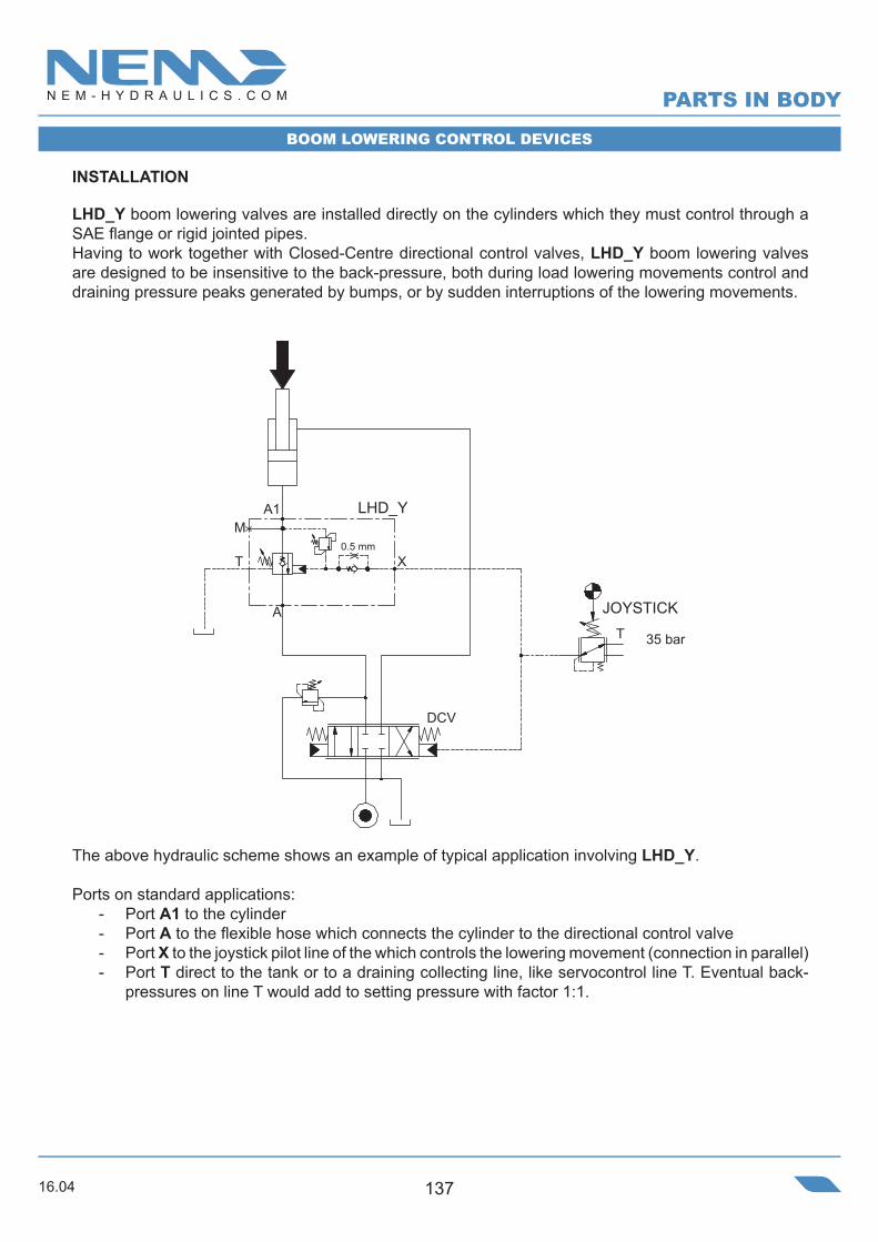
Y 5 0 0 1 Y 0 1
A,A1 G 1/2” SAE 10 5404
X,T G 1/4” SAE 06
5 - 14 7,52,52 3 200 - 400 350250
• Flow . . . . . . . . . . . . . . . . . . . . . . . . . . . . . . . . . . . . . . 60 l/min• Max working pressure . . . . . . . . . . . . . . . . . . . . . . . . .410 bar• Compensation. . . . . . . . . . . . . . .Fully Compensated with drain line• Weight . .. . . . . . . . . . . . . . . . . . . . . . . . . . . . . . . . . . . . 2,6 Kg• Tamper proof cap . . . . . . . . . . . . . . . . . . . . . .cod.9021030191 cod.9021015101
LOAD LOWERING CONTROL VALVE - LINE MOuNTED / RIGhT hAND
X
0.5mm
A1
A
T
M
A
Y5001Y14Steel Body G1/2” ; SAE-10
6
8
10
12
14
16
18
20
0
2
4
A1-A
A-A1
0 10 20 30 40 50 60
16.04 143
Ordering code
pos.1
pos.2
6
8
10
12
14
16
18
20
0
2
4
A1-A
A-A1
0 10 20 30 40 50 60
SPRING pos.1 SPRING pos.2 Setting Range
min.-max.[bar]
Pressure Increase[bar/turn]
Standard Setting @20 cc/min [bar]
Standard Setting @4 l/min [bar]
Setting Rangemin.-max.
[bar]
Pressure Increase[bar/turn]
Flow [l/min]
Pres
sure
Dro
p [b
ar]
80
68
35
45
98
64
9,5
20
4,5
40
23,
5
24135
15
T
X
A A1M
G 1/2”14
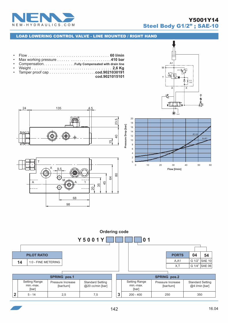
Y 5 0 0 2 Y 0 1
A,A1 SAE 10 5404
X,T G 1/4” SAE 06
5 - 14 7,52,5 3 200 - 400 3502502
Y5002Y14
LOAD LOWERING CONTROL VALVE - LINE MOuNTED / LEfT hAND
• Flow. . . . . . . . . . . . . . . . . . . . . . . . . . . . . . . . . . . . . . 60 l/min• Max working pressure . . . . . . . . . . . . . . . . . . . . . . . . .410 bar• Compensation. . . . . . . . . . . . . . .Fully Compensated with drain line• Weight. . . . . . . . . . . . . . . . . . . . . . . . . . . . . . . . . . . . . . 2,6 Kg• Tamper proof cap . . . . . . . . . . . . . . . . . . . . . .cod.9021030191 cod.9021015101
X
0.5mm
A1
A
T
M
Steel Body G1/2” ; SAE-10
PORTS
1:0 FINE METERING
PILOT RATIO

16.04144
Ordering code
11 1:0 - FINE METERING
PILOT RATIO
Y1001Y11
Y 1 0 0 1 Y 0 0
A,A1 G 1/2” SAE 10 5404
X,T G 1/4” SAE 06
5 - 14 7,52,52 3 200 - 400 350250
16
A
T
M
A1
X
8,5
13,5
43,5
78,5
34,5
53
32
70
8,5
==
121,5
2735
62,5 4,5
LOAD LOWERING CONTROL VALVE - LINE MOuNTED / RIGhT hAND
Steel Body G1/2” ; SAE-10
• Flow . . . . . . . . . . . . . . . . . . . . . . . . . . . . . . . . . . . . . . 75 l/min• Max working pressure . . . . . . . . . . . . . . . . . . . . . . . . .410 bar• Compensation. . . . . . . . . . . . . . .Fully Compensated with drain line• Weight. . . . . . . . . . . . . . . . . . . . . . . . . . . . . . . . . . . . . . 2,3 Kg• Tamper proof cap. . . . . . . . . . . . . . . . . . . . . . cod.9021030191
PORTS
SPRING pos.1 SPRING pos.2 Setting Range
min.-max.[bar]
Pressure Increase[bar/turn]
Standard Setting @20 cc/min [bar]
Standard Setting @4 l/min [bar]
Setting Rangemin.-max.
[bar]
Pressure Increase[bar/turn]
X
pos.1
pos.2
0.5mm
A1
A
T
M
0
10
20
30
40
50
0 10 20 30 40 50 60 70 80 90 100
Pres
sure
Dro
p [b
ar]
Flow [l/min]

16.04 145
Ordering code
11 1:0 FINE METERING
PILOT RATIO
16
A
T
M
A1
X
8,5
13,5
43,5
78,5
34,5 53
32
70
8,5
=
=
121,5
2735
62,54,5
Y1002Y11
Y 1 0 0 2 Y 0 0
A,A1 G 1/2” SAE 105404
X,T G 1/4” SAE 06
5 - 14 7,52,5 3 200 - 400 3502502
LOAD LOWERING CONTROL VALVE - LINE MOuNTED / LEfT hAND
Steel Body G1/2” ; SAE-10
• Flow . . . . . . . . . . . . . . . . . . . . . . . . . . . . . . . . . . . . . . 75 l/min• Max working pressure . . . . . . . . . . . . . . . . . . . . . . . . .410 bar• Compensation. . . . . . . . . . . . . . .Fully Compensated with drain line• Weight. . . . . . . . . . . . . . . . . . . . . . . . . . . . . . . . . . . . . . 2,3 Kg• Tamper proof cap. . . . . . . . . . . . . . . . . . . . . . cod.9021030191
PORTS
SPRING pos.1 SPRING pos.2 Setting Range
min.-max.[bar]
Pressure Increase[bar/turn]
Standard Setting @20 cc/min [bar]
Standard Setting @4 l/min [bar]
Setting Rangemin.-max.
[bar]
Pressure Increase[bar/turn]
X
pos.1
pos.2
0.5mm
A1
A
T
M
0
10
20
30
40
50
0 10 20 30 40 50 60 70 80 90 100
Pres
sure
Dro
p [b
ar]
Flow [l/min]
16.04146
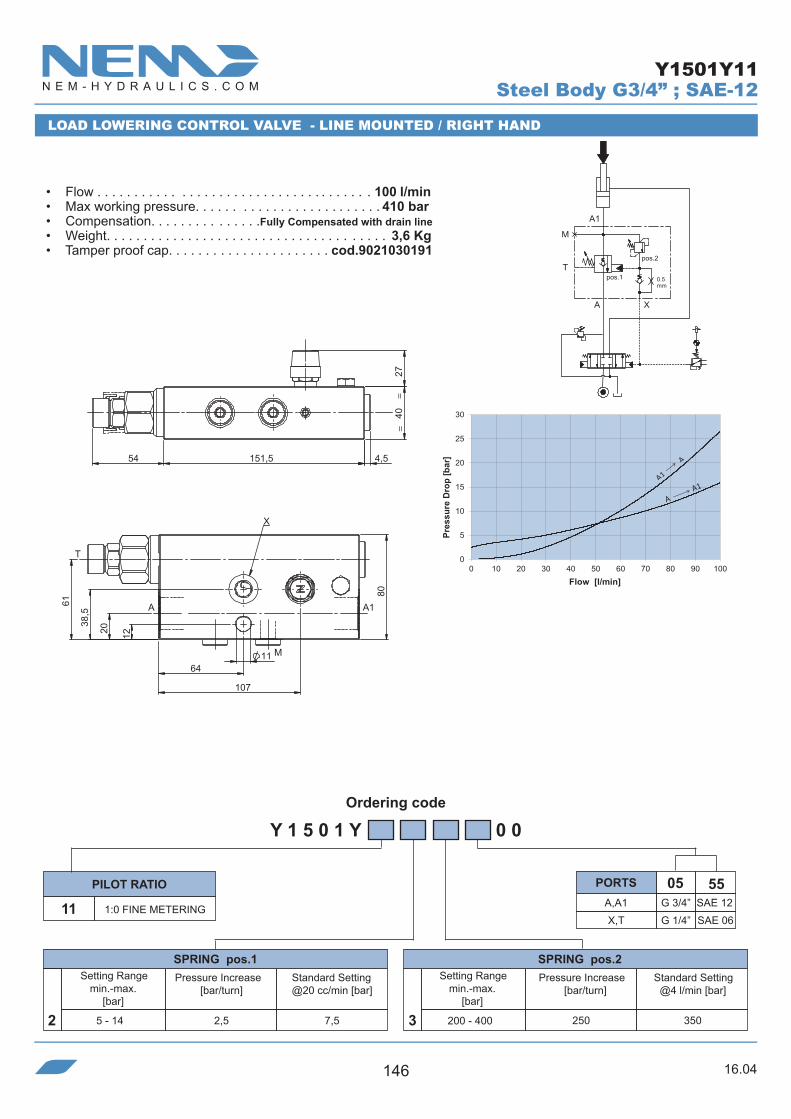
Ordering code
11 1:0 FINE METERING
PILOT RATIO
Y1501Y11
Y 1 5 0 1 Y 0 0
A,A1 G 3/4” SAE 12 5505
5 - 14 7,52,5 3 200 - 400 350250
X,T G 1/4” SAE 06
2
20
A1A
T
X
M
107
64
12
38,5
61
80
11
==
54
27
151,5 4,5
40
LOAD LOWERING CONTROL VALVE - LINE MOuNTED / RIGhT hAND
Steel Body G3/4” ; SAE-12
• Flow . . . . . . . . . . . . . . . . . . . . . . . . . . . . . . . . . . . . . 100 l/min• Max working pressure. . . . . . . . . . . . . . . . . . . . . . . . . 410 bar• Compensation. . . . . . . . . . . . . . .Fully Compensated with drain line• Weight. . . . . . . . . . . . . . . . . . . . . . . . . . . . . . . . . . . . . . 3,6 Kg• Tamper proof cap. . . . . . . . . . . . . . . . . . . . . . cod.9021030191
PORTS
SPRING pos.1 SPRING pos.2 Setting Range
min.-max.[bar]
Pressure Increase[bar/turn]
Standard Setting @20 cc/min [bar]
Standard Setting @4 l/min [bar]
Setting Rangemin.-max.
[bar]
Pressure Increase[bar/turn]
X
pos.1
pos.2
0.5mm
A1
A
T
M
0
5
10
15
20
25
30
0 10 20 30 40 50 60 70 80 90 100
Pres
sure
Dro
p [b
ar]
Flow [l/min]

16.04 147
Ordering code
11 1:0 - FINE METERING
PILOT RATIO
107
64
20
A
T
12
38,5
54
A1
X
M
61
80
11
=
=
27
151,54,5
40
Y1502Y11
Y 1 5 0 2 Y 0 0
A,A1 G 3/4” SAE 12 5505
X,T,M G 1/4” SAE 06
5 - 14 7,52,5 3 200 - 400 3502502
LOAD LOWERING CONTROL VALVE - LINE MOuNTED / LEfT hAND
Steel Body G3/4” ; SAE-12
• Flow . . . . . . . . . . . . . . . . . . . . . . . . . . . . . . . . . . . . . 100 l/min• Max working pressure. . . . . . . . . . . . . . . . . . . . . . . . . 410 bar• Compensation. . . . . . . . . . . . . . .Fully Compensated with drain line• Weight. . . . . . . . . . . . . . . . . . . . . . . . . . . . . . . . . . . . . . 3,6 Kg• Tamper proof cap. . . . . . . . . . . . . . . . . . . . . . cod.9021030191
PORTS
SPRING pos.1 SPRING pos.2 Setting Range
min.-max.[bar]
Pressure Increase[bar/turn]
Standard Setting @20 cc/min [bar]
Standard Setting @4 l/min [bar]
Setting Rangemin.-max.
[bar]
Pressure Increase[bar/turn]
X
pos.1
pos.2
0.5mm
A1
A
T
M
0
5
10
15
20
25
30
0 10 20 30 40 50 60 70 80 90 100
Pres
sure
Dro
p [b
ar]
Flow [l/min]

16.04148
Ordering code
SPRING CT2
SPRING CT1
Flange
Setting Rangemin.-max.
[bar]
Pressure Increase[bar/turn]
Standard Setting @20 cc/min [bar]
Standard Setting @4 l/min [bar]
Setting Rangemin.-max.
[bar]
Pressure Increase[bar/turn]
Pres
sure
Dro
p [b
ar]
8.5 N°4 THROUGH
274,
0
a
b
c
A1
4,5 169,5
253441,5
58
109
62,587
13
140,5
59,
16
A1
6
4,5
• Max flow. . . . . . . . . . . . . . . . . . . . . . . . . . . . .75 l/min• Max working pressure. . . . . . . . . . . . . . . . . . . 410 bar• Compensation . . . . . . . .Fully Compensated with drain line• Weight. . . . . . . . . . . . . . . . . . . . . . . . . . . . . . . . .3.9 Kg• Tamper proof cap CT1. . . . . . . . . . . . cod.9021030191• Tamper proof cap CT2 . . . . . . . . . .. . cod.9021015101
Y 1 0 1 3 Y 0 0
5 - 14 7,52,5
4 250 - 410 350250
2
A1
54
A G 1/2”
641/2 ”- SAE 6000
T-E-X G 1/4”
Y1013Y11
CT2
ATX
E
A1
AT
X
E
CT1
5
5
E
TXA
X
LOAD LOWERING CONTROL VALVE - SAE fLANGED 1/2”-SAE6000
18.2 40.5 8.5 a b c
18.64x3.53 NBR 70°SHO-Ring
1/2”- SAE 6000
Steel Body
Flow [l/min]
PORTS
11 1:0 FINE METERING
PILOT RATIO
15
20
25
30
35
40
45
50
0
5
10
0 15 30 45 60 75 90 105
A1 A
A A1
7 - 19 7,54,54

16.04 149
Ordering code
0 25 50 75 100 125 150
20
30
40
50
0
10
0
A1-A
A-A1
Flange
Pressure Increase[bar/turn]
Setting Rangemin.-max.
[bar]
Standard Setting @4 l/min [bar]
Pressure Increase[bar/turn]
Setting Rangemin.-max.
[bar]
Pres
sure
Dro
p [b
ar]
Y 1 5 1 3 Y 0 0
4 200 - 410 350250
SPRING CT2
A,A1
54
T-E-X G 1/4”
641/2 ”- SAE 6000
• Max flow . . . . . . . . . . . . . . . . . . . . . . . . . . . . .150 l/min• Max working pressure . . . . . . . . . . . . . . . . . . . 410 bar• Compensation. . . . . . . . .Fully Compensated with drain line• Weight . . . . . . . . . . . . . . . . . . . . . . . . . . . . . . . . 6.2 Kg• Tamper proof cap CT1. . . . . . . . . . . . cod.9021030191• Tamper proof cap CT2 . . . . . . . . . .. . cod.9021015101
18.2 40.5 8.5 M 8 18.64x3.53 NBR 70°SHa b c f O-Ring
Y1513Y11...64
a
b70
20
35
274,
5
c
A1
10.5 N°4 THROUGH
2004,5
69,5
5,5
b
f
6587
28,540
42
39,5
49,5
a
118
14,5
A1
CT2
ATX
E
A1
AT
X
E
CT1
SPRING CT1
5 - 16 4.5 7.54
LOAD LOWERING CONTROL VALVE - SAE fLANGED 1/2”-SAE6000
1/2”- SAE 6000
Steel Body
Flow [l/min]
Standard Setting @20 cc/min [bar]
PORTS11 1:0 - FINE METERING
PILOT RATIO
N°4+4 - M8

16.04150
Ordering code
0 50 100 150 200 250
20
30
40
50
0
10
A1-A
A-A1
Setting Rangemin.-max.
[bar]
Pressure Increase[bar/turn]
Standard Setting @20 cc/min [bar]
Standard Setting @4 l/min [bar]
Setting Rangemin.-max.
[bar]
Pressure Increase[bar/turn]
Pres
sure
Dro
p [b
ar]
Y 1 5 1 3 Y 0 0
SPRING CT1 SPRING CT2
5 - 16 7,54,5 4 200 - 410 3502504
A,A1
54
T-E-X G 1/4”
653/4 ”- SAE 6000
• Max flow. . . . . . . . . . . . . . . . . . . . . . . . . . . . 250 l/min• Max working pressure . . . . . . . . . . . . . . . . . . 410 bar• Compensation. . . . . . . . .Fully Compensated with drain line• Weight . . . . . . . . . . . . . . . . . . . . . . . . . . . . . . . . . 8 Kg• Tamper proof cap CT1. . . . . . . . . . . . cod.9021030191• Tamper proof cap CT2 . . . . . . . . . .. . cod.9021015101
23.8 50.8 10.5 M 10 23.39x3.53 NBR 70°SHa b c f O-Ring
Y1513Y11...65
a
b
40
25
804,
526
c
A1
10.5 N°4 THROUGH
77,599,5
33,548
,5
4,5 212,5 49,5b
f
79,5
39,5
5,5
42,5
a
127,5
17,5
A1
N°4+4 - M10
LOAD LOWERING CONTROL VALVE - SAE fLANGED 3/4”-SAE6000
3/4”- SAE 6000Flange
Steel Body
Flow [l/min]
11 1:0 FINE METERING
PILOT RATIO PORTS
E
X
T
A1
E
XT
A
CT CT1 2
16.04 151
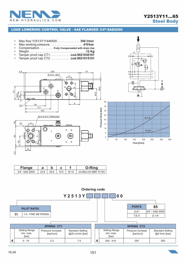
Ordering code
94117
150
34,5
20
61
ab
g
49,5
89,
4,5 249 61
f
A1
N°4+4 - M10
2690
4,5
25
a
b
c45
A1
E
T
X A
15
20
25
30
35
40
0
5
0 50 100 150 200 250 300 350
A1-A
A-A110
Flange
Setting Rangemin.-max.
[bar]
Pressure Increase[bar/turn]
Standard Setting @20 cc/min [bar]
Standard Setting @4 l/min [bar]
Setting Rangemin.-max.
[bar]
Pressure Increase[bar/turn]
Pres
sure
Dro
p [b
ar]
10.5 N°4 THROUGH
E
X
T
A1
E
XT
A
CT CT1 2
• Max flow Y2513Y11446500 . . . . . . . . . . . . . 350 l/min• Max working pressure. . . . . . . . . . . . . . . . . . . 410 bar• Compensation. . . . . . . . .Fully Compensated with drain line• Weight . . . . . . . . . . . . . . . . . . . . . . . . . . . . . . . . .12 Kg• Tamper proof cap CT1. . . . . . . . . . . . cod.9021030191• Tamper proof cap CT2 . . . . . . . . . .. . cod.9021015101
A,A1T,E,X G 1/4”
653/4 ”- SAE 6000
Y 2 5 1 3 Y 0 0
11
SPRING CT1
5 - 14 7.5
1:0 - FINE METERING
4 200 - 410 350250
SPRING CT2
4 2.3
Y2513Y11...65
LOAD LOWERING CONTROL VALVE - SAE fLANGED 3/4”-SAE6000
23.8 50.8 10.5 a b c f
M 10 24.99x3.53 NBR 70°SHO-Ring
3/4”- SAE 6000
Steel Body
Flow [l/min]
PILOT RATIO PORTS
5

16.04152
Ordering code
15
20
25
30
35
40
45
5
0
5
10
0 50 100 150 200 250 300 350 400
A1-A
A-A1
0
Flange
Setting Rangemin.-max.
[bar]
Pressure Increase[bar/turn]
Standard Setting @20 cc/min [bar]
Standard Setting @4 l/min [bar]
Setting Rangemin.-max.
[bar]
Pressure Increase[bar/turn]
Pres
sure
Dro
p [b
ar]
28,5
45
a
b
2690
4,5
120,
5
c
A1
12.5 N°4 THROUGH
612494,5
ab
94
117
150
34,561
20
46
49,5
89,5
4,5
f
A1
N°4+4 - M12
E
T
X A
E
X
T
A1
E
XT
A
CT CT1 2
Y2513Y11...66
661”- SAE 6000
G 1/4”
A,A1T,E,X
Y 2 5 1 3 Y 0 0
11
SPRING CT1
5 - 14 7.5
1:0 - FINE METERING
4 200 - 420 350250
SPRING CT2
4 2.3
• Max flow Y2513Y11446600 . . . . . . . . . . . . . 400 l/min• Max working pressure. . . . . . . . . . . . . . . . . . . 410 bar• Compensation. . . . . . . . .Fully Compensated with drain line• Weight . . . . . . . . . . . . . . . . . . . . . . . . . . . . . . . . .12 Kg• Tamper proof cap CT1. . . . . . . . . . . . cod.9021030191• Tamper proof cap CT2 . . . . . . . . . .. . cod.9021015101
LOAD LOWERING CONTROL VALVE - SAE fLANGED 1”-SAE6000
27.8 57.2 12.5 M 12 32.92x3.53 NBR 70°SHa b c f O-Ring
1”- SAE 6000
Steel Body
Flow [l/min]
PORTSPILOT RATIO

16.04 153
Ordering code
Flange
Setting Rangemin.-max.
[bar]
Pressure Increase[bar/turn]
Standard Setting @20 cc/min [bar]
Standard Setting @4 l/min [bar]
Setting Rangemin.-max.
[bar]
Pressure Increase[bar/turn]
E
X
T
A1
E
XT
A
CT CT1 2
Y2513Y11...67
671”-1/4 - SAE 6000
G 1/4”
A,A1T,E,X
Y 2 5 1 3 Y 0 0
11
SPRING CT1
5 - 14 7.5
1:0 - FINE METERING
4 200 - 420 350250
SPRING CT2
4 2.3
• Max flow Y2513Y11446700 . . . . . . . . . . . . . 400 l/min• Max working pressure. . . . . . . . . . . . . . . . . . . 410 bar• Compensation. . . . . . . . .Fully Compensated with drain line• Weight . . . . . . . . . . . . . . . . . . . . . . . . . . . . . . . . .15 Kg• Tamper proof cap CT1. . . . . . . . . . . . cod.9021030191• Tamper proof cap CT2 . . . . . . . . . .. . cod.9021015101
LOAD LOWERING CONTROL VALVE - SAE fLANGED 1”-1/4 - SAE6000
31.8 66.7 14.5 M 14 40.87x3.53 NBR 70°SHa b c f O-Ring
1”-1/4 SAE 6000
Steel Body
PORTSPILOT RATIO
A
95,5
121,5
151,5
47
49,
5
253,5 4,5 58
f
a
b
99,
5 4
,5
24 4
3,5 6
8
A1
N° 4+4 - M12
132
27,
4 1
00
b
a
c
4,5
32
50
Ø14 N°4 THROUGH
A1
A
15
20
25
30
35
40
45
5
0
5
10
0 50 100 150 200 250 300 350 400
A1-A
A-A1
0
Pres
sure
Dro
p [b
ar]
Flow [l/min]

16.04154
Ordering code
Pres
sure
Dro
p [b
ar]
h1001C51
H 1 0 0 1 C S 0 0
A,A1 G 1/2” SAE 10
540451 4:1
85
290
120 - 410
4
X,E G 1/4” SAE 06
A1
A BL E X
E X
2
==
2
40
E
1AA
X
BL
115
18,52545
59,5
69,5
1837 52
16,2
56,5
SINGLE ACTING COuNTERBALANCE VALVE - BACK-PRESSuRE COMPENSATED
Steel Body G1/2” ; SAE-10
• Flow . . . . . . . . . . . . . . . . . . . . . . . . . . . . . . . . . . . . . 110 l/min• Max working pressure. . . . . . . . . . . . . . . . . . . . . . . . . 410 bar• Compensation. . . . . . . . . . . . . . . . . . . . . Fully Compensated• Weight. . . . . . . . . . . . . . . . . . . . . . . . . . . . . . . . . . . . . . 3,5 Kg• Tamper proof cap. . . . . . . . . . . . . . . . . . . . . . cod.9021030190
Note:- Pressure setting must be 30% higher than pressure induced by load.- Valve pre-arranged for electric bypass assembly
PORTSPILOT RATIO SPRINGS
Setting Rangemin.-max.
[bar]
Pressure Increase[bar/turn]
Standard Setting 4 l/min [bar]
Flow [l/min]
N°2 HOLES Ø8,5
0 10 20 30 40 50 60 70 80 90 100
30
25
20
15
10
5
0
A1 A
A A
1

16.04 155
Ordering code
Pres
sure
Dro
p [b
ar]
0 10 20 30 40 50 60 70 80 90 100
30
25
20
15
10
5
0
A1
A (E
V excit
ed)
A A1
A1 A
(piloted)
Flow [l/min]
SINGLE ACTING COuNTERBALANCE VALVE WITh ELECTRIC BYPASS
h1001N50
H 1 0 0 1 N S 0 0
A,A1 G 1/2” SAE 10
PORTS 540450 4:1 + BPE
PILOT RATIO
85
260
120 - 410
4SPRINGS
X,E G 1/4” SAE 06
A1 XE
XBL EA
2
==
2
40
E
1AA
X
BL18,525
16,2
45
59,5
69,5
1837 52
56,5115 26,7
46
5,7
39,5
Steel Body G1/2” ; SAE-10
• Flow . . . . . . . . . . . . . . . . . . . . . . . . . . . . . . . . . . . . . 110 l/min• Max working pressure. . . . . . . . . . . . . . . . . . . . . . . . . 350 bar• Compensation. . . . . . . . . . . . . . . . . . . . . . Not Compensated • Weight. . . . . . . . . . . . . . . . . . . . . . . . . . . . . . . . . . . . . . 3,6 Kg• Tamper proof cap. . . . . . . . . . . . . . . . . . . . . . cod.9021030190• Coil to be ordered separately (page )
Setting Rangemin.-max.
[bar]
Pressure Increase[bar/turn]
Standard Setting 4 l/min [bar]
Note:- Pressure setting must be 30% higher than pressure induced by load.- Back pressure can influence the opening pressure (LHD10X-C is recommended for circuits with high back pressure)
N°2 HOLES Ø8,5
09400 189

16.04156
Ordering code
• Flow. . . . . . . . . . . . . . . . . . . . . . . . . . . . . . . 75 l/min• Max working pressure . . . . . . . . . . . . . . . . . . 350 bar• Compensation . . . . . . . . Fully Compensated with drain line• Weight. . . . . . . . . . . . . . . . . . . . . . . . . . . . . . . . .2.6 Kg• Tamper proof cap. . . . . . . . . . . . . . . . cod.9021030191
M
M
XT
A1 X
A
Standard Setting 4 l/min [bar]
Setting Rangemin.-max.
[bar]
1:0 FINE METERING
Y 1 0 2 3 Y 0 0 0
A,A1 G 1/2” SAE 10
PORTS 5404PILOT RATIO
11T,X,X1,M G 1/4” SAE 06
2.5
7,5/+0,5
5 - 14
2SPRING
Pressure Increase[bar/turn]
BOOM LOWERING CONTROL VALVE fOR fRONT LOADER
8
2
69,5
4,5
121,54 ,562,5
3013,575
109
33,5
52
6
54
404,
54,
5
X
A A1M
N°2 HOLES 8,5
Steel Body G1/2” ; SAE-10Y1023Y11
Flow [l/min]
Pres
sure
Dro
p [b
ar]
0 15 30 45 60 75 90 105
60
50
40
30
20
10
0
A1 AA
A1
Note:- Hydraulic joystick operated valve for front loaders.- Connect T port direct to tank by a drain line.- The valve does not operate for pressure relief.
T

16.04 157
Ordering code
40=
=4,
54,
5
N°2 HOLES 8,5
121,562,5
69,5
5,7
39,5
33,5
52
13,5
75109
30
20
6
54X
1M
8
2
Standard Setting 4 l/min [bar]
Setting Rangemin.-max.
[bar]
1:0 FINE METERING + BPE
Y 1 0 2 3 Y S 0 1
A,A1 G 1/2” SAE 10
PORTS 5404PILOT RATIO
12T,X,X1 G 1/4” SAE 06
2.5
7,5/+0,5
5 - 14
2SPRING
Pressure Increase[bar/turn]
• Flow. . . . . . . . . . . . . . . . . . . . . . . . . . . . . . . 75 l/min• Max working pressure . . . . . . . . . . . . . . . . . . 350 bar• Compensation . . . . . . . . Fully Compensated with drain line• Weight. . . . . . . . . . . . . . . . . . . . . . . . . . . . . . . . .3.6 Kg• Tamper proof cap. . . . . . . . . . . . . . . . cod.9021030191• Coil to be ordered separately (page )
MA1 X
T X1MA
BOOM LOWERING CONTROL VALVE fOR fRONT LOADER WITh BY PASS
Y1023Y12Steel Body G1/2” ; SAE-10
Flow [l/min]
Pres
sure
Dro
p [b
ar]
0 15 30 45 60 75 90 105
60
50
40
30
20
10
0
A1 AA
A1
Note:- Hydraiulic joystick operated valve for front loaders equipped with solenoid operated bay-pass for floating function.- Connect T port direct to tank by a drain line.- The valve does not operate for pressure relief.
AA
09400 189
T