Embed Size (px)
Citation preview
Boolean Algebra and Logic Gates
Prof. Wangrok Oh
Dept. of Information Communications Eng.Chungnam National University
Prof. Wangrok Oh(CNU) 1 / 50
Overview
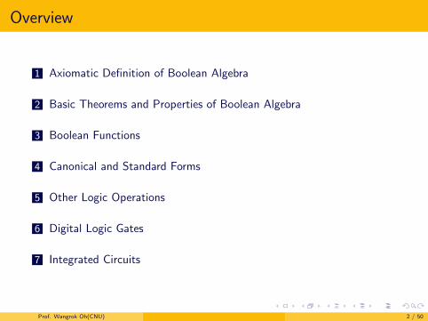
1 Axiomatic Definition of Boolean Algebra
2 Basic Theorems and Properties of Boolean Algebra
3 Boolean Functions
4 Canonical and Standard Forms
5 Other Logic Operations
6 Digital Logic Gates
7 Integrated Circuits
Prof. Wangrok Oh(CNU) 2 / 50
Axiomatic Definition of Boolean Algebra
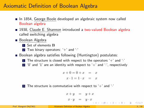
In 1854, George Boole developed an algebraic system now calledBoolean algebra
1938, Claude E. Shannon introduced a two-valued Boolean algebracalled switching algebra
Boolean Algebra
1 Set of elements B2 Two binary operators: ‘+’ and ‘·’
Boolean algebra satisfies following (Huntington) postulates:
1 The structure is closed with respect to the operators ‘+’ and ‘·’2 ‘0’ and ‘1’ are an identity with respect to ‘+’ and ‘·’, respectively
x+ 0 = 0 + x = x
x · 1 = 1 · x = x
3 The structure is commutative with respect to ‘+’ and ‘·’
x+ y = y + x
x · y = y · x
Prof. Wangrok Oh(CNU) Axiomatic Definition of Boolean Algebra 3 / 50
Axiomatic Definition of Boolean Algebra
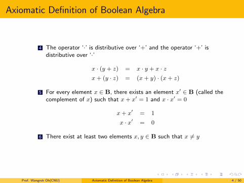
4 The operator ‘·’ is distributive over ‘+’ and the operator ‘+’ isdistributive over ‘·’
x · (y + z) = x · y + x · zx+ (y · z) = (x+ y) · (x+ z)
5 For every element x ∈ B, there exists an element x′ ∈ B (called thecomplement of x) such that x+ x′ = 1 and x · x′ = 0
x+ x′ = 1
x · x′ = 0
6 There exist at least two elements x, y ∈ B such that x 6= y
Prof. Wangrok Oh(CNU) Axiomatic Definition of Boolean Algebra 4 / 50
Axiomatic Definition of Boolean Algebra
Two-Valued Boolean Algebra
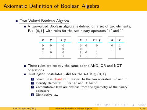
A two-valued Boolean algebra is defined on a set of two elements,B ∈ {0, 1} with rules for the two binary operators ‘+’ and ‘·’
Section 2.3 Axiomatic Definition of Boolean Algebra 41
3. Boolean algebra does not have additive or multiplicative inverses; therefore, there are no subtraction or division operations.
4. Postulate 5 defines an operator called the complement that is not available in ordinary algebra.
5. Ordinary algebra deals with the real numbers, which constitute an infinite set of elements. Boolean algebra deals with the as yet undefined set of elements, B, but in the two‐valued Boolean algebra defined next (and of interest in our subse-quent use of that algebra), B is defined as a set with only two elements, 0 and 1.
Boolean algebra resembles ordinary algebra in some respects. The choice of the symbols + and # is intentional, to facilitate Boolean algebraic manipulations by persons already familiar with ordinary algebra. Although one can use some knowledge from ordinary algebra to deal with Boolean algebra, the beginner must be careful not to substitute the rules of ordinary algebra where they are not applicable.
It is important to distinguish between the elements of the set of an algebraic structure and the variables of an algebraic system. For example, the elements of the field of real numbers are numbers, whereas variables such as a, b, c, etc., used in ordinary algebra, are symbols that stand for real numbers. Similarly, in Boolean algebra, one defines the elements of the set B, and variables such as x, y, and z are merely symbols that represent the elements. At this point, it is important to realize that, in order to have a Boolean algebra, one must show that
1. the elements of the set B, 2. the rules of operation for the two binary operators, and 3. the set of elements, B, together with the two operators, satisfy the six Huntington
postulates.
One can formulate many Boolean algebras, depending on the choice of elements of B and the rules of operation. In our subsequent work, we deal only with a two‐valued Boolean algebra (i.e., a Boolean algebra with only two elements). Two‐valued Boolean algebra has applications in set theory (the algebra of classes) and in propositional logic. Our interest here is in the application of Boolean algebra to gate‐type circuits commonly used in digital devices and computers.
Two‐Valued Boolean Algebra
A two‐valued Boolean algebra is defined on a set of two elements, B = {0, 1}, with rules for the two binary operators + and # as shown in the following operator tables (the rule for the complement operator is for verification of postulate 5):
x y x # y x y x ! y x x"
0 0 0 0 0 0 0 1 0 1 0 0 1 1 1 0 1 0 0 1 0 1 1 1 1 1 1 1
These rules are exactly the same as the AND, OR and NOToperationsHuntington postulates valid for the set B ∈ {0, 1}
1 Structure is closed with respect to the two operators ‘+’ and ‘·’2 Identity elements: ‘0’ for ‘+’ and ‘1’ for ‘·’3 Commutative laws are obvious from the symmetry of the binary
operators4 Distributive law
Prof. Wangrok Oh(CNU) Axiomatic Definition of Boolean Algebra 5 / 50
Axiomatic Definition of Boolean Algebra
42 Chapter 2 Boolean Algebra and Logic Gates
These rules are exactly the same as the AND, OR, and NOT operations, respectively, defined in Table 1.8. We must now show that the Huntington postulates are valid for the set B = {0, 1} and the two binary operators + and # .
1. That the structure is closed with respect to the two operators is obvious from the tables, since the result of each operation is either 1 or 0 and 1, 0 H B.
2. From the tables, we see that
(a) 0 + 0 = 0 0 + 1 = 1 + 0 = 1; (b) 1 # 1 = 1 1 # 0 = 0 # 1 = 0. This establishes the two identity elements, 0 for + and 1 for # , as defined by
postulate 2. 3. The commutative laws are obvious from the symmetry of the binary operator tables.
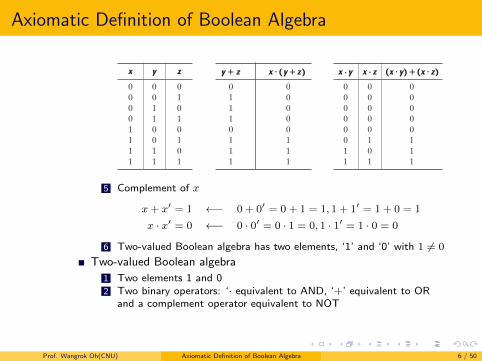
4. (a) The distributive law x # (y + z) = (x # y) + (x # z) can be shown to hold from the operator tables by forming a truth table of all possible values of x, y, and z. For each combination, we derive x # (y + z) and show that the value is the same as the value of (x # y) + (x # z):
x y z y ! z x # (y !z) x # y x # z (x # y) !(x # z)
0 0 0 0 0 0 0 0 0 0 1 1 0 0 0 0 0 1 0 1 0 0 0 0 0 1 1 1 0 0 0 0 1 0 0 0 0 0 0 0 1 0 1 1 1 0 1 1 1 1 0 1 1 1 0 1 1 1 1 1 1 1 1 1
(b) The distributive law of + over # can be shown to hold by means of a truth table similar to the one in part (a).
5. From the complement table, it is easily shown that
(a) x + x ! = 1, since 0 + 0! = 0 + 1 = 1 and 1 + 1! = 1 + 0 = 1. (b) x # x! = 0, since 0 # 0! = 0 # 1 = 0 and 1 # 1! = 1 # 0 = 0. Thus, postulate 1 is verified. 6. Postulate 6 is satisfied because the two‐valued Boolean algebra has two elements,
1 and 0, with 1 ! 0.
We have just established a two‐valued Boolean algebra having a set of two elements, 1 and 0, two binary operators with rules equivalent to the AND and OR operations, and a complement operator equivalent to the NOT operator. Thus, Boolean algebra has been defined in a formal mathematical manner and has been shown to be equivalent to the binary logic presented heuristically in Section 1.9. The heuristic presentation is helpful in understanding the application of Boolean algebra to gate‐type circuits. The formal
5 Complement of x
x+ x′ = 1 ←− 0 + 0′ = 0 + 1 = 1, 1 + 1′ = 1 + 0 = 1
x · x′ = 0 ←− 0 · 0′ = 0 · 1 = 0, 1 · 1′ = 1 · 0 = 0
6 Two-valued Boolean algebra has two elements, ‘1’ and ‘0’ with 1 6= 0
Two-valued Boolean algebra
1 Two elements 1 and 02 Two binary operators: ‘· equivalent to AND, ‘+’ equivalent to OR
and a complement operator equivalent to NOT
Prof. Wangrok Oh(CNU) Axiomatic Definition of Boolean Algebra 6 / 50
Basic Theorems and Properties of Boolean Algebra
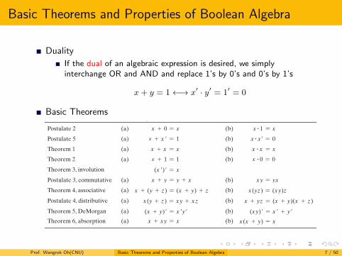
Duality
If the dual of an algebraic expression is desired, we simplyinterchange OR and AND and replace 1’s by 0’s and 0’s by 1’s
x+ y = 1←→ x′ · y′ = 1′ = 0
Basic Theorems
Section 2.4 Basic Theorems and Properties of Boolean Algebra 43
presentation is necessary for developing the theorems and properties of the algebraic system. The two‐valued Boolean algebra defined in this section is also called “switching algebra” by engineers. To emphasize the similarities between two‐valued Boolean alge-bra and other binary systems, that algebra was called “binary logic” in Section 1.9. From here on, we shall drop the adjective “two‐valued” from Boolean algebra in subsequent discussions.
2 . 4 B A S I C T H E O R E M S A N D P R O P E R T I E S O F B O O L E A N A L G E B R A
Duality
In Section 2.3, the Huntington postulates were listed in pairs and designated by part (a) and part (b). One part may be obtained from the other if the binary operators and the identity elements are interchanged. This important property of Boolean algebra is called the duality principle and states that every algebraic expression deducible from the postulates of Boolean algebra remains valid if the operators and identity elements are interchanged. In a two‐valued Boolean algebra, the identity elements and the ele-ments of the set B are the same: 1 and 0. The duality principle has many applications. If the dual of an algebraic expression is desired, we simply interchange OR and AND operators and replace 1’s by 0’s and 0’s by 1’s.
Basic Theorems
Table 2.1 lists six theorems of Boolean algebra and four of its postulates. The notation is simplified by omitting the binary operator whenever doing so does not lead to confusion. The theorems and postulates listed are the most basic relationships in Boolean
Table 2.1 Postulates and Theorems of Boolean Algebra
Postulate 2 (a) x + 0 = x (b) x # 1 = x
Postulate 5 (a) x + x ! = 1 (b) x # x! = 0
Theorem 1 (a) x + x = x (b) x # x = x
Theorem 2 (a) x + 1 = 1 (b) x # 0 = 0
Theorem 3, involution (x !)! = x
Postulate 3, commutative (a) x + y = y + x (b) xy = yx
Theorem 4, associative (a) x + (y + z) = (x + y) + z (b) x(yz) = (xy)z
Postulate 4, distributive (a) x(y + z) = xy + xz (b) x + yz = (x + y)(x + z)
Theorem 5, DeMorgan (a) (x + y)! = x !y! (b) (xy)! = x ! + y!
Theorem 6, absorption (a) x + xy = x (b) x(x + y) = x
Prof. Wangrok Oh(CNU) Basic Theorems and Properties of Boolean Algebra 7 / 50
Basic Theorems and Properties of Boolean Algebra
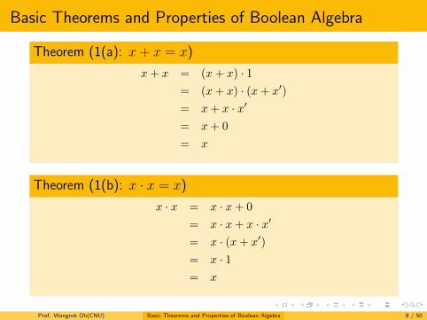
Theorem (1(a): x+ x = x)
x+ x = (x+ x) · 1= (x+ x) · (x+ x′)
= x+ x · x′
= x+ 0
= x
Theorem (1(b): x · x = x)
x · x = x · x+ 0
= x · x+ x · x′
= x · (x+ x′)
= x · 1= x
Prof. Wangrok Oh(CNU) Basic Theorems and Properties of Boolean Algebra 8 / 50
Basic Theorems and Properties of Boolean Algebra
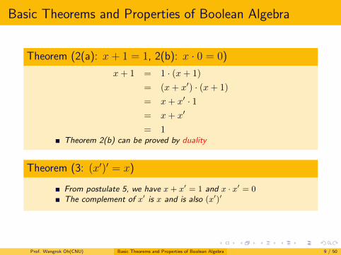
Theorem (2(a): x+ 1 = 1, 2(b): x · 0 = 0)
x+ 1 = 1 · (x+ 1)
= (x+ x′) · (x+ 1)
= x+ x′ · 1= x+ x′
= 1Theorem 2(b) can be proved by duality
Theorem (3: (x′)′ = x)
From postulate 5, we have x+ x′ = 1 and x · x′ = 0The complement of x′ is x and is also (x′)′
Prof. Wangrok Oh(CNU) Basic Theorems and Properties of Boolean Algebra 9 / 50
Basic Theorems and Properties of Boolean Algebra
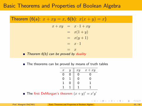
Theorem (6(a): x+ xy = x, 6(b): x(x+ y) = x)
x+ xy = x · 1 + xy
= x(1 + y)
= x(y + 1)
= x · 1= x
Theorem 6(b) can be proved by duality
The theorems can be proved by means of truth tables
x y xy x+ xy
0 0 0 00 1 0 01 0 0 11 1 1 1
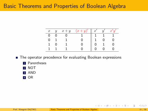
The first DeMorgan’s theorem (x+ y)′ = x′y′
Prof. Wangrok Oh(CNU) Basic Theorems and Properties of Boolean Algebra 10 / 50
Basic Theorems and Properties of Boolean Algebra
x y x+ y (x+ y)′ x′ y′ x′y′
0 0 0 1 1 1 10 1 1 0 1 0 01 0 1 0 0 1 01 1 1 0 0 0 0
The operator precedence for evaluating Boolean expressions
1 Parentheses
2 NOT
3 AND
4 OR
Prof. Wangrok Oh(CNU) Basic Theorems and Properties of Boolean Algebra 11 / 50
Boolean Functions
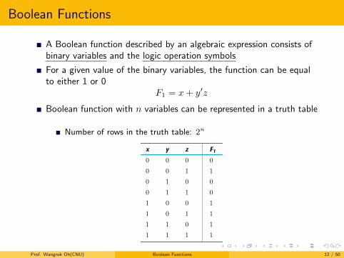
A Boolean function described by an algebraic expression consists ofbinary variables and the logic operation symbols
For a given value of the binary variables, the function can be equalto either 1 or 0
F1 = x+ y′z
Boolean function with n variables can be represented in a truth table
Number of rows in the truth table: 2n
46 Chapter 2 Boolean Algebra and Logic Gates
Table 2.2 Truth Tables for F1 and F2
x y z F1 F2
0 0 0 0 0
0 0 1 1 1
0 1 0 0 0
0 1 1 0 1
1 0 0 1 1
1 0 1 1 1
1 1 0 1 0
1 1 1 1 0
result then complemented. The right side of the expression is x!y!, so the complement of x and the complement of y are both evaluated first and the result is then ANDed. Note that in ordinary arithmetic, the same precedence holds (except for the comple-ment) when multiplication and addition are replaced by AND and OR, respectively.
2 . 5 B O O L E A N F U N C T I O N S
Boolean algebra is an algebra that deals with binary variables and logic operations. A Boolean function described by an algebraic expression consists of binary variables, the constants 0 and 1, and the logic operation symbols. For a given value of the binary variables, the function can be equal to either 1 or 0. As an example, consider the Boolean function
F1 = x + y!z
The function F1 is equal to 1 if x is equal to 1 or if both y! and z are equal to 1. F1 is equal to 0 otherwise. The complement operation dictates that when y! = 1, y = 0. Therefore, F1 = 1 if x = 1 or if y = 0 and z = 1. A Boolean function expresses the logical rela-tionship between binary variables and is evaluated by determining the binary value of the expression for all possible values of the variables.
A Boolean function can be represented in a truth table. The number of rows in the truth table is 2n, where n is the number of variables in the function. The binary combina-tions for the truth table are obtained from the binary numbers by counting from 0 through 2n - 1. Table 2.2 shows the truth table for the function F1. There are eight pos-sible binary combinations for assigning bits to the three variables x, y, and z. The column labeled F1 contains either 0 or 1 for each of these combinations. The table shows that the function is equal to 1 when x = 1 or when yz = 01 and is equal to 0 otherwise.
A Boolean function can be transformed from an algebraic expression into a circuit diagram composed of logic gates connected in a particular structure. The logic‐circuit diagram (also called a schematic) for F1 is shown in Fig. 2.1 . There is an inverter for input y to generate its complement. There is an AND gate for the term y!z and an OR gate
Prof. Wangrok Oh(CNU) Boolean Functions 12 / 50
Boolean Functions
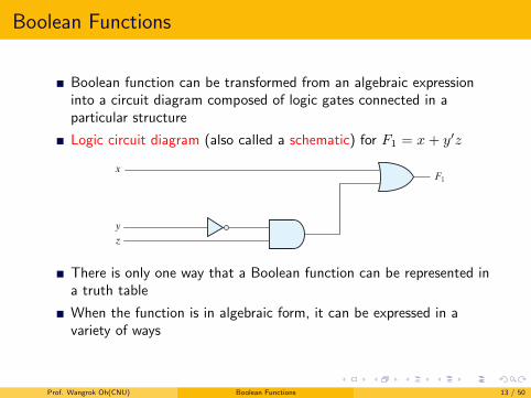
Boolean function can be transformed from an algebraic expressioninto a circuit diagram composed of logic gates connected in aparticular structure
Logic circuit diagram (also called a schematic) for F1 = x+ y′zSection 2.5 Boolean Functions 47
that combines x with y!z. In logic‐circuit diagrams, the variables of the function are taken as the inputs of the circuit and the binary variable F1 is taken as the output of the circuit. The schematic expresses the relationship between the output of the circuit and its inputs. Rather than listing each combination of inputs and outputs, it indicates how to compute the logic value of each output from the logic values of the inputs.
There is only one way that a Boolean function can be represented in a truth table. However, when the function is in algebraic form, it can be expressed in a variety of ways, all of which have equivalent logic. The particular expression used to represent the function will dictate the interconnection of gates in the logic‐circuit diagram. Conversely, the inter-connection of gates will dictate the logic expression. Here is a key fact that motivates our use of Boolean algebra: By manipulating a Boolean expression according to the rules of Boolean algebra, it is sometimes possible to obtain a simpler expression for the same function and thus reduce the number of gates in the circuit and the number of inputs to the gate. Designers are motivated to reduce the complexity and number of gates because their effort can significantly reduce the cost of a circuit. Consider, for example, the fol-lowing Boolean function:
F2 = x!y!z + x!yz + xy!
A schematic of an implementation of this function with logic gates is shown in Fig. 2.2 (a). Input variables x and y are complemented with inverters to obtain x! and y!. The three terms in the expression are implemented with three AND gates. The OR gate forms the logical OR of the three terms. The truth table for F2 is listed in Table 2.2 . The function is equal to 1 when xyz = 001 or 011 or when xy = 10 (irre-spective of the value of z) and is equal to 0 otherwise. This set of conditions produces four 1’s and four 0’s for F2.
Now consider the possible simplification of the function by applying some of the identities of Boolean algebra:
F2 = x!y!z + x!yz + xy! = x!z(y! + y) + xy! = x!z + xy!
The function is reduced to only two terms and can be implemented with gates as shown in Fig. 2.2 (b). It is obvious that the circuit in (b) is simpler than the one in (a), yet both implement the same function. By means of a truth table, it is possible to verify that the two expressions are equivalent. The simplified expression is equal to 1 when xz = 01 or when xy = 10. This produces the same four 1’s in the truth table. Since both expressions
F1x
yz
FIGURE 2.1 Gate implementation of F1 ! x " y!z There is only one way that a Boolean function can be represented in
a truth table
When the function is in algebraic form, it can be expressed in avariety of ways
Prof. Wangrok Oh(CNU) Boolean Functions 13 / 50
Boolean Functions
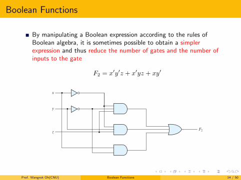
By manipulating a Boolean expression according to the rules ofBoolean algebra, it is sometimes possible to obtain a simplerexpression and thus reduce the number of gates and the number ofinputs to the gate
F2 = x′y′z + x′yz + xy′
48 Chapter 2 Boolean Algebra and Logic Gates
produce the same truth table, they are equivalent. Therefore, the two circuits have the same outputs for all possible binary combinations of inputs of the three variables. Each circuit implements the same identical function, but the one with fewer gates and fewer inputs to gates is preferable because it requires fewer wires and components. In general, there are many equivalent representations of a logic function. Finding the most eco-nomic representation of the logic is an important design task.
Algebraic Manipulation
When a Boolean expression is implemented with logic gates, each term requires a gate and each variable within the term designates an input to the gate. We define a literal to be a single variable within a term, in complemented or uncomplemented form. The function of Fig. 2.2 (a) has three terms and eight literals, and the one in Fig. 2.2 (b) has two terms and four literals. By reducing the number of terms, the number of literals, or both in a Boolean expression, it is often possible to obtain a simpler circuit. The manip-ulation of Boolean algebra consists mostly of reducing an expression for the purpose of obtaining a simpler circuit. Functions of up to five variables can be simplified by the map method described in the next chapter. For complex Boolean functions and many
(a) F2 ! x"y"z # x"yz # xy"
(b) F2 ! xy" # x"z
x
y
zF2
x
y
z
F2
FIGURE 2.2 Implementation of Boolean function F2 with gates
Prof. Wangrok Oh(CNU) Boolean Functions 14 / 50
Boolean Functions
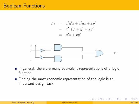
F2 = x′y′z + x′yz + xy′
= x′z(y′ + y) + xy′
= x′z + xy′
48 Chapter 2 Boolean Algebra and Logic Gates
produce the same truth table, they are equivalent. Therefore, the two circuits have the same outputs for all possible binary combinations of inputs of the three variables. Each circuit implements the same identical function, but the one with fewer gates and fewer inputs to gates is preferable because it requires fewer wires and components. In general, there are many equivalent representations of a logic function. Finding the most eco-nomic representation of the logic is an important design task.
Algebraic Manipulation
When a Boolean expression is implemented with logic gates, each term requires a gate and each variable within the term designates an input to the gate. We define a literal to be a single variable within a term, in complemented or uncomplemented form. The function of Fig. 2.2 (a) has three terms and eight literals, and the one in Fig. 2.2 (b) has two terms and four literals. By reducing the number of terms, the number of literals, or both in a Boolean expression, it is often possible to obtain a simpler circuit. The manip-ulation of Boolean algebra consists mostly of reducing an expression for the purpose of obtaining a simpler circuit. Functions of up to five variables can be simplified by the map method described in the next chapter. For complex Boolean functions and many
(a) F2 ! x"y"z # x"yz # xy"
(b) F2 ! xy" # x"z
x
y
zF2
x
y
z
F2
FIGURE 2.2 Implementation of Boolean function F2 with gates
In general, there are many equivalent representations of a logicfunction
Finding the most economic representation of the logic is animportant design task
Prof. Wangrok Oh(CNU) Boolean Functions 15 / 50
Boolean Functions
Algebraic Manipulation
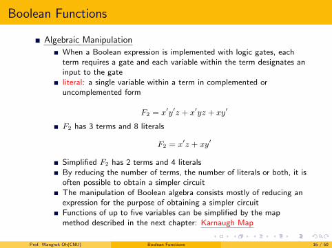
When a Boolean expression is implemented with logic gates, eachterm requires a gate and each variable within the term designates aninput to the gateliteral: a single variable within a term in complemented oruncomplemented form
F2 = x′y′z + x′yz + xy′
F2 has 3 terms and 8 literals
F2 = x′z + xy′
Simplified F2 has 2 terms and 4 literalsBy reducing the number of terms, the number of literals or both, it isoften possible to obtain a simpler circuitThe manipulation of Boolean algebra consists mostly of reducing anexpression for the purpose of obtaining a simpler circuitFunctions of up to five variables can be simplified by the mapmethod described in the next chapter: Karnaugh Map
Prof. Wangrok Oh(CNU) Boolean Functions 16 / 50
Boolean Functions
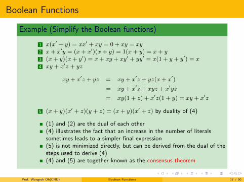
Example (Simplify the Boolean functions)
1 x(x′ + y) = xx′ + xy = 0 + xy = xy2 x+ x′y = (x+ x′)(x+ y) = 1(x+ y) = x+ y3 (x+ y)(x+ y′) = x+ xy + xy′ + yy′ = x(1 + y + y′) = x4 xy + x′z + yz
xy + x′z + yz = xy + x′z + yz(x+ x′)
= xy + x′z + xyz + x′yz
= xy(1 + z) + x′z(1 + y) = xy + x′z
5 (x+ y)(x′ + z)(y + z) = (x+ y)(x′ + z) by duality of (4)
(1) and (2) are the dual of each other(4) illustrates the fact that an increase in the number of literalssometimes leads to a simpler final expression(5) is not minimized directly, but can be derived from the dual of thesteps used to derive (4)(4) and (5) are together known as the consensus theorem
Prof. Wangrok Oh(CNU) Boolean Functions 17 / 50
Boolean Functions
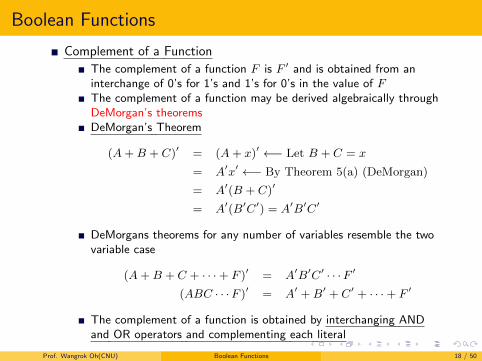
Complement of a Function
The complement of a function F is F ′ and is obtained from aninterchange of 0’s for 1’s and 1’s for 0’s in the value of FThe complement of a function may be derived algebraically throughDeMorgan’s theoremsDeMorgan’s Theorem
(A+B + C)′ = (A+ x)′ ←− Let B + C = x
= A′x′ ←− By Theorem 5(a) (DeMorgan)
= A′(B + C)′
= A′(B′C′) = A′B′C′
DeMorgans theorems for any number of variables resemble the twovariable case
(A+B + C + · · ·+ F )′ = A′B′C′ · · ·F ′
(ABC · · ·F )′ = A′ +B′ + C′ + · · ·+ F ′
The complement of a function is obtained by interchanging ANDand OR operators and complementing each literal
Prof. Wangrok Oh(CNU) Boolean Functions 18 / 50
Boolean Functions
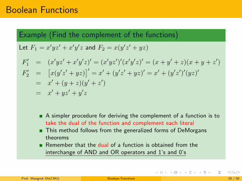
Example (Find the complement of the functions)
Let F1 = x′yz′ + x′y′z and F2 = x(y′z′ + yz)
F ′1 = (x′yz′ + x′y′z)′ = (x′yz′)′(x′y′z)′ = (x+ y′ + z)(x+ y + z′)
F ′2 =
[x(y′z′ + yz)
]′= x′ + (y′z′ + yz)′ = x′ + (y′z′)′(yz)′
= x′ + (y + z)(y′ + z′)
= x′ + yz′ + y′z
A simpler procedure for deriving the complement of a function is totake the dual of the function and complement each literalThis method follows from the generalized forms of DeMorganstheoremsRemember that the dual of a function is obtained from theinterchange of AND and OR operators and 1’s and 0’s
Prof. Wangrok Oh(CNU) Boolean Functions 19 / 50
Boolean Functions
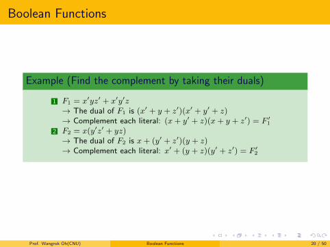
Example (Find the complement by taking their duals)
1 F1 = x′yz′ + x′y′z→ The dual of F1 is (x′ + y + z′)(x′ + y′ + z)→ Complement each literal: (x+ y′ + z)(x+ y + z′) = F ′
1
2 F2 = x(y′z′ + yz)→ The dual of F2 is x+ (y′ + z′)(y + z)→ Complement each literal: x′ + (y + z)(y′ + z′) = F ′
2
Prof. Wangrok Oh(CNU) Boolean Functions 20 / 50
Canonical and Standard Forms
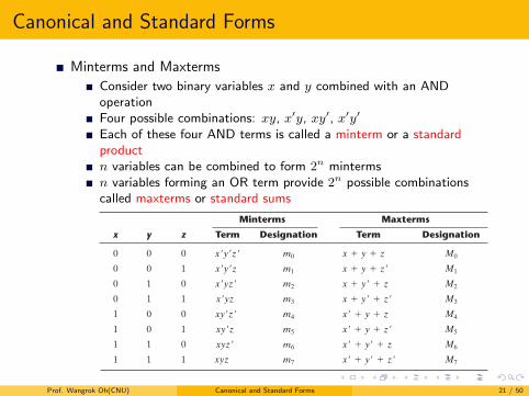
Minterms and Maxterms
Consider two binary variables x and y combined with an ANDoperationFour possible combinations: xy, x′y, xy′, x′y′
Each of these four AND terms is called a minterm or a standardproductn variables can be combined to form 2n mintermsn variables forming an OR term provide 2n possible combinationscalled maxterms or standard sums
Section 2.6 Canonical and Standard Forms 51
2 . 6 C A N O N I C A L A N D S TA N D A R D F O R M S
Minterms and Maxterms
A binary variable may appear either in its normal form (x) or in its complement form (x!). Now consider two binary variables x and y combined with an AND operation. Since each variable may appear in either form, there are four possible combinations: x!y!, x!y, xy!, and xy. Each of these four AND terms is called a minterm, or a standard product. In a similar manner, n variables can be combined to form 2n minterms. The 2n different min-terms may be determined by a method similar to the one shown in Table 2.3 for three variables. The binary numbers from 0 to 2n - 1 are listed under the n variables. Each minterm is obtained from an AND term of the n variables, with each variable being primed if the corresponding bit of the binary number is a 0 and unprimed if a 1. A symbol for each minterm is also shown in the table and is of the form mj, where the subscript j denotes the decimal equivalent of the binary number of the minterm designated.
In a similar fashion, n variables forming an OR term, with each variable being primed or unprimed, provide 2n possible combinations, called maxterms, or standard sums. The eight maxterms for three variables, together with their symbolic designations, are listed in Table 2.3 . Any 2n maxterms for n variables may be determined similarly. It is impor-tant to note that (1) each maxterm is obtained from an OR term of the n variables, with each variable being unprimed if the corresponding bit is a 0 and primed if a 1, and (2) each maxterm is the complement of its corresponding minterm and vice versa.
A Boolean function can be expressed algebraically from a given truth table by form-ing a minterm for each combination of the variables that produces a 1 in the function and then taking the OR of all those terms. For example, the function f1 in Table 2.4 is determined by expressing the combinations 001, 100, and 111 as x!y!z, xy!z!, and xyz, respectively. Since each one of these minterms results in f1 = 1, we have
f1 = x!y!z + xy!z! + xyz = m1 + m4 + m7
Table 2.3Minterms and Maxterms for Three Binary Variables
Minterms Maxterms
x y z Term Designation Term Designation
0 0 0 x!y!z! m0 x + y + z M0
0 0 1 x!y!z m1 x + y + z! M1
0 1 0 x!yz! m2 x + y! + z M2
0 1 1 x!yz m3 x + y! + z! M3
1 0 0 xy!z! m4 x! + y + z M4
1 0 1 xy!z m5 x! + y + z! M5
1 1 0 xyz! m6 x! + y! + z M6
1 1 1 xyz m7 x! + y! + z! M7
Prof. Wangrok Oh(CNU) Canonical and Standard Forms 21 / 50
Canonical and Standard Forms
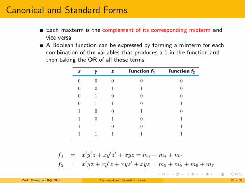
Each maxterm is the complement of its corresponding midterm andvice versaA Boolean function can be expressed by forming a minterm for eachcombination of the variables that produces a 1 in the function andthen taking the OR of all those terms
52 Chapter 2 Boolean Algebra and Logic Gates
Similarly, it may be easily verified that
f2 = x!yz + xy!z + xyz! + xyz = m3 + m5 + m6 + m7
These examples demonstrate an important property of Boolean algebra: Any Boolean function can be expressed as a sum of minterms (with “sum” meaning the ORing of terms).
Now consider the complement of a Boolean function. It may be read from the truth table by forming a minterm for each combination that produces a 0 in the function and then ORing those terms. The complement of f1 is read as
f =1 = x!y!z! + x!yz! + x!yz + xy!z + xyz!
If we take the complement of f =1, we obtain the function f1:
f1 = (x + y + z)(x + y! + z)(x! + y + z!)(x! + y! + z) = M0
# M2# M3
# M5# M6
Similarly, it is possible to read the expression for f2 from the table:
f2 = (x + y + z)(x + y + z!)(x + y! + z)(x! + y + z) = M0M1M2M4
These examples demonstrate a second property of Boolean algebra: Any Boolean func-tion can be expressed as a product of maxterms (with “product” meaning the ANDing of terms). The procedure for obtaining the product of maxterms directly from the truth table is as follows: Form a maxterm for each combination of the variables that produces a 0 in the function, and then form the AND of all those maxterms. Boolean functions expressed as a sum of minterms or product of maxterms are said to be in canonical form .
Sum of Minterms
Previously, we stated that, for n binary variables, one can obtain 2n distinct minterms and that any Boolean function can be expressed as a sum of minterms. The minterms whose sum defines the Boolean function are those which give the 1’s of the function in a
Table 2.4Functions of Three Variables
x y z Function f1 Function f2
0 0 0 0 0
0 0 1 1 0
0 1 0 0 0
0 1 1 0 1
1 0 0 1 0
1 0 1 0 1
1 1 0 0 1
1 1 1 1 1
f1 = x′y′z + xy′z′ + xyz = m1 +m4 +m7
f2 = x′yz + xy′z + xyz′ + xyz = m3 +m5 +m6 +m7
Prof. Wangrok Oh(CNU) Canonical and Standard Forms 22 / 50
Canonical and Standard Forms
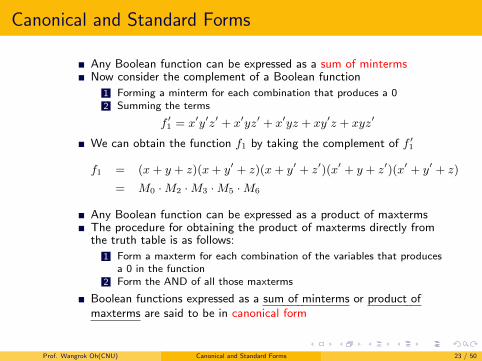
Any Boolean function can be expressed as a sum of mintermsNow consider the complement of a Boolean function
1 Forming a minterm for each combination that produces a 02 Summing the terms
f ′1 = x′y′z′ + x′yz′ + x′yz + xy′z + xyz′
We can obtain the function f1 by taking the complement of f ′1
f1 = (x+ y + z)(x+ y′ + z)(x+ y′ + z′)(x′ + y + z′)(x′ + y′ + z)
= M0 ·M2 ·M3 ·M5 ·M6
Any Boolean function can be expressed as a product of maxtermsThe procedure for obtaining the product of maxterms directly fromthe truth table is as follows:
1 Form a maxterm for each combination of the variables that producesa 0 in the function
2 Form the AND of all those maxterms
Boolean functions expressed as a sum of minterms or product ofmaxterms are said to be in canonical form
Prof. Wangrok Oh(CNU) Canonical and Standard Forms 23 / 50
Canonical and Standard Forms
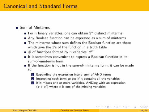
Sum of Minterms
For n binary variables, one can obtain 2n distinct minterms
Any Boolean function can be expressed as a sum of minterms
The minterms whose sum defines the Boolean function are thosewhich give the 1’s of the function in a truth table
# of functions formed by n variables: 22n
It is sometimes convenient to express a Boolean function in itssum-of-minterms formIf the function is not in the sum-of-minterms form, it can be madeso:
1 Expanding the expression into a sum of AND terms2 Inspecting each term to see if it contains all the variables3 If it misses one or more variables, ANDing with an expression
(x+ x′) where x is one of the missing variables
Prof. Wangrok Oh(CNU) Canonical and Standard Forms 24 / 50
Canonical and Standard Forms
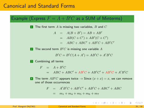
Example (Express F = A+B′C as a SUM of Minterms)
1 The first term A is missing two variables, B and C
A = A(B +B′) = AB +AB′
= AB(C + C′) +AB′(C + C′)
= ABC +ABC′ +AB′C +AB′C′
2 The second term B′C is missing one variable A
B′C = B′C(A+A′) = AB′C +A′B′C
3 Combining all terms
F = A+B′C
= ABC +ABC′ +AB′C +AB′C′ +AB′C +A′B′C
4 The term AB′C appears twice → Since (x+ x) = x, we can removeone of those occurrences
F = A′B′C +AB′C′ +AB′C +ABC′ +ABC
= m1 +m4 +m5 +m6 +m7
Prof. Wangrok Oh(CNU) Canonical and Standard Forms 25 / 50
Canonical and Standard Forms
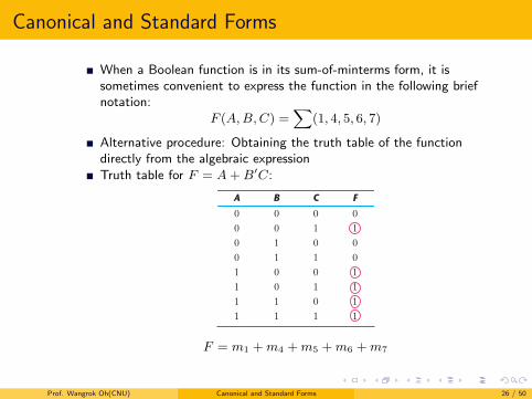
When a Boolean function is in its sum-of-minterms form, it issometimes convenient to express the function in the following briefnotation:
F (A,B,C) =∑
(1, 4, 5, 6, 7)
Alternative procedure: Obtaining the truth table of the functiondirectly from the algebraic expressionTruth table for F = A+B′C:
54 Chapter 2 Boolean Algebra and Logic Gates
1’s under F for those combinations for which A = 1 and BC = 01. From the truth table, we can then read the five minterms of the function to be 1, 4, 5, 6, and 7.
Product of Maxterms
Each of the 22n functions of n binary variables can be also expressed as a product of maxterms. To express a Boolean function as a product of maxterms, it must first be brought into a form of OR terms. This may be done by using the distributive law, x + yz = (x + y)(x + z). Then any missing variable x in each OR term is ORed with xx!. The procedure is clarified in the following example.
EXAMPLE 2.5
Express the Boolean function F = xy + x!z as a product of maxterms. First, convert the function into OR terms by using the distributive law:
F = xy + x!z = (xy + x!)(xy + z) = (x + x!)(y + x!)(x + z)(y + z) = (x! + y)(x + z)(y + z)
The function has three variables: x, y, and z. Each OR term is missing one variable; therefore,
x! + y = x! + y + zz! = (x! + y + z)(x! + y + z!) x + z = x + z + yy! = (x + y + z)(x + y! + z) y + z = y + z + xx! = (x + y + z)(x! + y + z)
Combining all the terms and removing those which appear more than once, we finally obtain
F = (x + y + z)(x + y! + z)(x! + y + z)(x! + y + z!) = M0M2M4M5
Table 2.5Truth Table for F ! A " B!C
A B C F
0 0 0 00 0 1 10 1 0 00 1 1 01 0 0 11 0 1 11 1 0 11 1 1 1
F = m1 +m4 +m5 +m6 +m7
Prof. Wangrok Oh(CNU) Canonical and Standard Forms 26 / 50
Canonical and Standard Forms
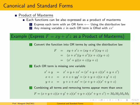
Product of MaxtermsEach functions can be also expressed as a product of maxterms
1 Express each term with an OR form ←− Using the distributive law2 Any missing variable x in each OR term is ORed with xx′
Example (Express F = xy + x′z as a Product of Maxterms)
1 Convert the function into OR terms by using the distributive law
F = xy + x′z = (xy + x′)(xy + z)
= (x+ x′)(y + x′)(x+ z)(y + z)
= (x′ + y)(x+ z)(y + z)
2 Each OR term is missing one variable
x′ + y = x′ + y + zz′ = (x′ + y + z)(x′ + y + z′)
x+ z = x+ z + yy′ = (x+ y + z)(x+ y′ + z)
y + z = y + z + xx′ = (x+ y + z)(x′ + y + z)
3 Combining all terms and removing terms appear more than once
F = (x+ y+ z)(x+ y′ + z)(x′ + y+ z)(x′ + y+ z′) = M0M2M4M5
Prof. Wangrok Oh(CNU) Canonical and Standard Forms 27 / 50
Canonical and Standard Forms
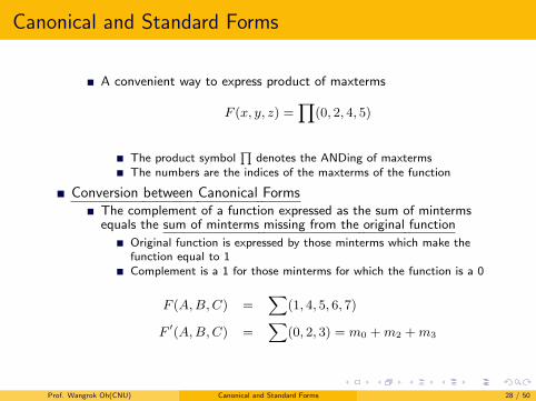
A convenient way to express product of maxterms
F (x, y, z) =∏
(0, 2, 4, 5)
The product symbol∏
denotes the ANDing of maxtermsThe numbers are the indices of the maxterms of the function
Conversion between Canonical FormsThe complement of a function expressed as the sum of mintermsequals the sum of minterms missing from the original function
Original function is expressed by those minterms which make thefunction equal to 1Complement is a 1 for those minterms for which the function is a 0
F (A,B,C) =∑
(1, 4, 5, 6, 7)
F ′(A,B,C) =∑
(0, 2, 3) = m0 +m2 +m3
Prof. Wangrok Oh(CNU) Canonical and Standard Forms 28 / 50
Canonical and Standard Forms
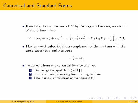
If we take the complement of F ′ by Demorgan’s theorem, we obtainF in a different form
F = (m0 +m2 +m3)′ = m′
0 ·m′2 ·m′
3 = M0M2M3 =∏
(0, 2, 3)
Maxterm with subscript j is a complement of the minterm with thesame subscript j and vice versa
m′j = Mj
To convert from one canonical form to another:
1 Interchange the symbols∑
and∏
2 List those numbers missing from the original form3 Total number of minterms or maxterms is 2n
Prof. Wangrok Oh(CNU) Canonical and Standard Forms 29 / 50
Canonical and Standard Forms
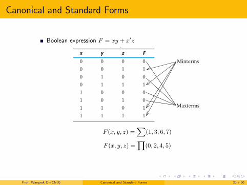
Boolean expression F = xy + x′z
56 Chapter 2 Boolean Algebra and Logic Gates
Since there is a total of eight minterms or maxterms in a function of three variables, we determine the missing terms to be 0, 2, 4, and 5. The function expressed as a product of maxterms is
F(x, y, z) = !(0, 2, 4, 5)
the same answer as obtained in Example 2.5.
Standard Forms
The two canonical forms of Boolean algebra are basic forms that one obtains from read-ing a given function from the truth table. These forms are very seldom the ones with the least number of literals, because each minterm or maxterm must contain, by definition, all the variables, either complemented or uncomplemented.
Another way to express Boolean functions is in standard form. In this configuration, the terms that form the function may contain one, two, or any number of literals. There are two types of standard forms: the sum of products and products of sums.
The sum of products is a Boolean expression containing AND terms, called product terms, with one or more literals each. The sum denotes the ORing of these terms. An example of a function expressed as a sum of products is
F1 = y" + xy + x"yz"
The expression has three product terms, with one, two, and three literals. Their sum is, in effect, an OR operation.
The logic diagram of a sum‐of‐products expression consists of a group of AND gates followed by a single OR gate. This configuration pattern is shown in Fig. 2.3 (a). Each product term requires an AND gate, except for a term with a single literal. The logic sum is formed with an OR gate whose inputs are the outputs of the AND gates and the single literal. It is assumed that the input variables are directly available in their comple-ments, so inverters are not included in the diagram. This circuit configuration is referred to as a two‐level implementation.
Table 2.6Truth Table for F ! xy " x"z
x y z F
0 0 0 00 0 1 10 1 0 00 1 1 11 0 0 01 0 1 01 1 0 11 1 1 1
Minterms
Maxterms
F (x, y, z) =∑
(1, 3, 6, 7)
F (x, y, z) =∏
(0, 2, 4, 5)
Prof. Wangrok Oh(CNU) Canonical and Standard Forms 30 / 50
Canonical and Standard Forms
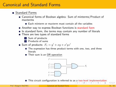
Standard Forms
Canonical forms of Boolean algebra: Sum of minterms/Product ofmaxterms
Each minterm or maxterm must contain all the variables
Another way to express Boolean functions is standard formIn standard form, the terms may contain any number of literalsThere are two types of standard forms
1 Sum of products2 Products of sums
Sum of products: F1 = y′ + xy + x′yz′
The expression has three product terms with one, two, and threeliteralsTheir sum is an OR operation
Section 2.6 Canonical and Standard Forms 57
A product of sums is a Boolean expression containing OR terms, called sum terms. Each term may have any number of literals. The product denotes the ANDing of these terms. An example of a function expressed as a product of sums is
F2 = x(y! + z)(x! + y + z!)
This expression has three sum terms, with one, two, and three literals. The product is an AND operation. The use of the words product and sum stems from the similarity of the AND operation to the arithmetic product (multiplication) and the similarity of the OR operation to the arithmetic sum (addition). The gate structure of the product‐of‐sums expression consists of a group of OR gates for the sum terms (except for a single literal), followed by an AND gate, as shown in Fig. 2.3 (b). This standard type of expression results in a two‐level structure of gates.
A Boolean function may be expressed in a nonstandard form. For example, the function
F3 = AB + C(D + E)
is neither in sum‐of‐products nor in product‐of‐sums form. The implementation of this expression is shown in Fig. 2.4 (a) and requires two AND gates and two OR gates. There are three levels of gating in this circuit. It can be changed to a standard form by using the distributive law to remove the parentheses:
F3 = AB + C(D + E) = AB + CD + CE
y!
F1
x!
z!y
xy
F2
x
y!
y
z
z
x!
(a) Sum of Products (b) Product of Sums
FIGURE 2.3Two‐level implementation
F3
ABCDE
(a) AB " C(D " E) (b) AB " CD " CE
A
F3
B
DC
CE
FIGURE 2.4Three‐ and two‐level implementation
This circuit configuration is referred to as a two-level implementation
Prof. Wangrok Oh(CNU) Canonical and Standard Forms 31 / 50
Canonical and Standard Forms
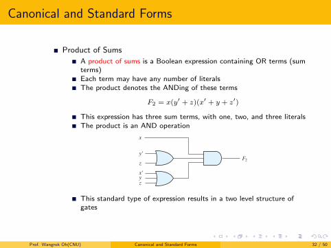
Product of Sums
A product of sums is a Boolean expression containing OR terms (sumterms)Each term may have any number of literalsThe product denotes the ANDing of these terms
F2 = x(y′ + z)(x′ + y + z′)
This expression has three sum terms, with one, two, and three literalsThe product is an AND operation
Section 2.6 Canonical and Standard Forms 57
A product of sums is a Boolean expression containing OR terms, called sum terms. Each term may have any number of literals. The product denotes the ANDing of these terms. An example of a function expressed as a product of sums is
F2 = x(y! + z)(x! + y + z!)
This expression has three sum terms, with one, two, and three literals. The product is an AND operation. The use of the words product and sum stems from the similarity of the AND operation to the arithmetic product (multiplication) and the similarity of the OR operation to the arithmetic sum (addition). The gate structure of the product‐of‐sums expression consists of a group of OR gates for the sum terms (except for a single literal), followed by an AND gate, as shown in Fig. 2.3 (b). This standard type of expression results in a two‐level structure of gates.
A Boolean function may be expressed in a nonstandard form. For example, the function
F3 = AB + C(D + E)
is neither in sum‐of‐products nor in product‐of‐sums form. The implementation of this expression is shown in Fig. 2.4 (a) and requires two AND gates and two OR gates. There are three levels of gating in this circuit. It can be changed to a standard form by using the distributive law to remove the parentheses:
F3 = AB + C(D + E) = AB + CD + CE
y!
F1
x!
z!y
xy
F2
x
y!
y
z
z
x!
(a) Sum of Products (b) Product of Sums
FIGURE 2.3Two‐level implementation
F3
ABCDE
(a) AB " C(D " E) (b) AB " CD " CE
A
F3
B
DC
CE
FIGURE 2.4Three‐ and two‐level implementation
This standard type of expression results in a two level structure ofgates
Prof. Wangrok Oh(CNU) Canonical and Standard Forms 32 / 50
Canonical and Standard Forms
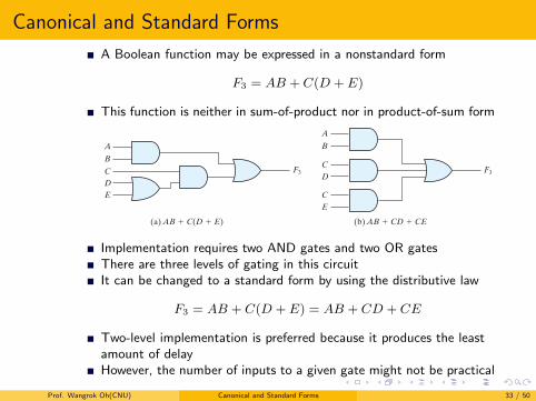
A Boolean function may be expressed in a nonstandard form
F3 = AB + C(D + E)
This function is neither in sum-of-product nor in product-of-sum form
Section 2.6 Canonical and Standard Forms 57
A product of sums is a Boolean expression containing OR terms, called sum terms. Each term may have any number of literals. The product denotes the ANDing of these terms. An example of a function expressed as a product of sums is
F2 = x(y! + z)(x! + y + z!)
This expression has three sum terms, with one, two, and three literals. The product is an AND operation. The use of the words product and sum stems from the similarity of the AND operation to the arithmetic product (multiplication) and the similarity of the OR operation to the arithmetic sum (addition). The gate structure of the product‐of‐sums expression consists of a group of OR gates for the sum terms (except for a single literal), followed by an AND gate, as shown in Fig. 2.3 (b). This standard type of expression results in a two‐level structure of gates.
A Boolean function may be expressed in a nonstandard form. For example, the function
F3 = AB + C(D + E)
is neither in sum‐of‐products nor in product‐of‐sums form. The implementation of this expression is shown in Fig. 2.4 (a) and requires two AND gates and two OR gates. There are three levels of gating in this circuit. It can be changed to a standard form by using the distributive law to remove the parentheses:
F3 = AB + C(D + E) = AB + CD + CE
y!
F1
x!
z!y
xy
F2
x
y!
y
z
z
x!
(a) Sum of Products (b) Product of Sums
FIGURE 2.3Two‐level implementation
F3
ABCDE
(a) AB " C(D " E) (b) AB " CD " CE
A
F3
B
DC
CE
FIGURE 2.4Three‐ and two‐level implementationImplementation requires two AND gates and two OR gatesThere are three levels of gating in this circuitIt can be changed to a standard form by using the distributive law
F3 = AB + C(D + E) = AB + CD + CE
Two-level implementation is preferred because it produces the leastamount of delayHowever, the number of inputs to a given gate might not be practical
Prof. Wangrok Oh(CNU) Canonical and Standard Forms 33 / 50
Other Logic Operations
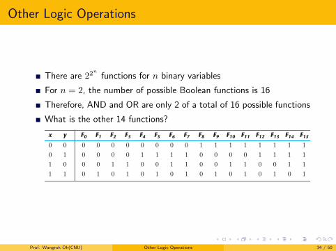
There are 22n
functions for n binary variables
For n = 2, the number of possible Boolean functions is 16
Therefore, AND and OR are only 2 of a total of 16 possible functions
What is the other 14 functions?
58 Chapter 2 Boolean Algebra and Logic Gates
The sum‐of‐products expression is implemented in Fig. 2.4 (b). In general, a two‐level implementation is preferred because it produces the least amount of delay through the gates when the signal propagates from the inputs to the output. However, the number of inputs to a given gate might not be practical.
2 . 7 O T H E R L O G I C O P E R AT I O N S
When the binary operators AND and OR are placed between two variables, x and y, they form two Boolean functions, x # y and x + y, respectively. Previously we stated that there are 22n functions for n binary variables. Thus, for two variables, n = 2, and the number of possible Boolean functions is 16. Therefore, the AND and OR functions are only 2 of a total of 16 possible functions formed with two binary variables. It would be instructive to find the other 14 functions and investigate their properties.
The truth tables for the 16 functions formed with two binary variables are listed in Table 2.7 . Each of the 16 columns, F0 to F15, represents a truth table of one possible func-tion for the two variables, x and y. Note that the functions are determined from the 16 binary combinations that can be assigned to F. The 16 functions can be expressed algebraically by means of Boolean functions, as is shown in the first column of Table 2.8 . The Boolean expressions listed are simplified to their minimum number of literals.
Although each function can be expressed in terms of the Boolean operators AND, OR, and NOT, there is no reason one cannot assign special operator symbols for express-ing the other functions. Such operator symbols are listed in the second column of Table 2.8 . However, of all the new symbols shown, only the exclusive‐OR symbol, !, is in common use by digital designers.
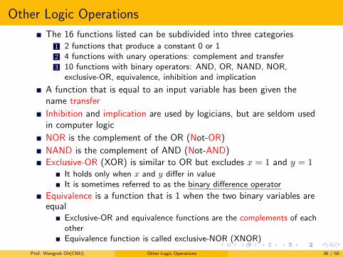
Each of the functions in Table 2.8 is listed with an accompanying name and a com-ment that explains the function in some way.1 The 16 functions listed can be subdivided into three categories:
1. Two functions that produce a constant 0 or 1. 2. Four functions with unary operations: complement and transfer. 3. Ten functions with binary operators that define eight different operations: AND,
OR, NAND, NOR, exclusive‐OR, equivalence, inhibition, and implication.
Table 2.7Truth Tables for the 16 Functions of Two Binary Variables
x y F0 F1 F2 F3 F4 F5 F6 F7 F8 F9 F10 F11 F12 F13 F14 F15
0 0 0 0 0 0 0 0 0 0 1 1 1 1 1 1 1 10 1 0 0 0 0 1 1 1 1 0 0 0 0 1 1 1 11 0 0 0 1 1 0 0 1 1 0 0 1 1 0 0 1 11 1 0 1 0 1 0 1 0 1 0 1 0 1 0 1 0 1
1 The symbol ˆ is also used to indicate the exclusive or operator, e.g., xˆy. The symbol for the AND function is sometimes omitted from the product of two variables, e.g., xy.
Prof. Wangrok Oh(CNU) Other Logic Operations 34 / 50
Other Logic OperationsSection 2.7 Other Logic Operations 59
Constants for binary functions can be equal to only 1 or 0. The complement function produces the complement of each of the binary variables. A function that is equal to an input variable has been given the name transfer, because the variable x or y is transferred through the gate that forms the function without changing its value. Of the eight binary operators, two (inhibition and implication) are used by logicians, but are seldom used in computer logic. The AND and OR operators have been mentioned in conjunction with Boolean algebra. The other four functions are used extensively in the design of digital systems.
The NOR function is the complement of the OR function, and its name is an abbreviation of not‐OR. Similarly, NAND is the complement of AND and is an abbreviation of not‐AND. The exclusive‐OR, abbreviated XOR, is similar to OR, but excludes the combination of both x and y being equal to 1; it holds only when x and y differ in value. (It is sometimes referred to as the binary difference operator.) Equiv-alence is a function that is 1 when the two binary variables are equal (i.e., when both are 0 or both are 1). The exclusive‐OR and equivalence functions are the comple-ments of each other. This can be easily verified by inspecting Table 2.7 : The truth table for exclusive‐OR is F6 and for equivalence is F9, and these two functions are the complements of each other. For this reason, the equivalence function is called exclusive‐NOR, abbreviated XNOR.
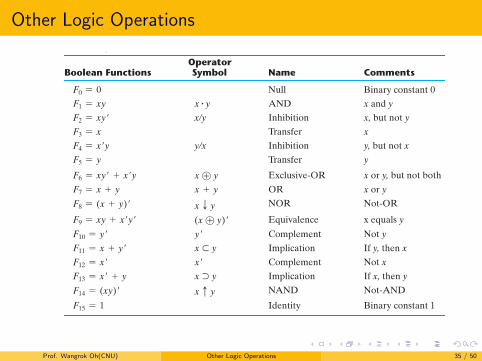
Table 2.8Boolean Expressions for the 16 Functions of Two Variables
Boolean FunctionsOperator Symbol Name Comments
F0 = 0 Null Binary constant 0F1 = xy x # y AND x and yF2 = xy! x/y Inhibition x, but not yF3 = x Transfer xF4 = x!y y/x Inhibition y, but not xF5 = y Transfer y
F6 = xy! + x!y x ! y Exclusive‐OR x or y, but not bothF7 = x + y x + y OR x or yF8 = (x + y)! x T y NOR Not‐OR
F9 = xy + x!y! (x ! y)! Equivalence x equals yF10 = y! y! Complement Not yF11 = x + y! x ! y Implication If y, then xF12 = x! x! Complement Not xF13 = x! + y x " y Implication If x, then yF14 = (xy)! x c y NAND Not‐AND
F15 = 1 Identity Binary constant 1
Prof. Wangrok Oh(CNU) Other Logic Operations 35 / 50
Other Logic Operations
The 16 functions listed can be subdivided into three categories1 2 functions that produce a constant 0 or 12 4 functions with unary operations: complement and transfer3 10 functions with binary operators: AND, OR, NAND, NOR,
exclusive-OR, equivalence, inhibition and implication
A function that is equal to an input variable has been given thename transfer
Inhibition and implication are used by logicians, but are seldom usedin computer logic
NOR is the complement of the OR (Not-OR)
NAND is the complement of AND (Not-AND)Exclusive-OR (XOR) is similar to OR but excludes x = 1 and y = 1
It holds only when x and y differ in valueIt is sometimes referred to as the binary difference operator
Equivalence is a function that is 1 when the two binary variables areequal
Exclusive-OR and equivalence functions are the complements of eachotherEquivalence function is called exclusive-NOR (XNOR)
Prof. Wangrok Oh(CNU) Other Logic Operations 36 / 50
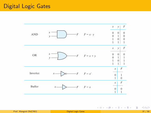
Digital Logic Gates Section 2.8 Digital Logic Gates 61
NameGraphicsymbol
Algebraicfunction
Truthtable
AND
OR
Inverter
Buffer
NAND
NOR
Exclusive-OR(XOR)
Exclusive-NORor
equivalence
F ! x · y
F ! x " y
F ! (xy)#
F ! x#
F ! x
x y F
x y F
x y F
x y F
x y F
x y F
x F
x F
F ! (x " y)#
F ! xy# " x#y
F ! xy " x#y#
F
F
Fx
Fx
F
F
F
Fx
y
xy
xy ! x ! y
! (x ! y)#
0011
0101
0011
0101
0111
01
10
01
01
0011
0101
1110
0011
0101
1000
0011
0101
0110
0011
0101
1001
0001
xy
xy
xy
FIGURE 2.5Digital logic gates
Prof. Wangrok Oh(CNU) Digital Logic Gates 37 / 50
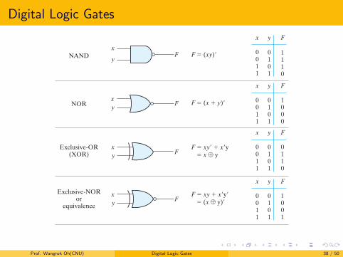
Digital Logic Gates
Section 2.8 Digital Logic Gates 61
NameGraphicsymbol
Algebraicfunction
Truthtable
AND
OR
Inverter
Buffer
NAND
NOR
Exclusive-OR(XOR)
Exclusive-NORor
equivalence
F ! x · y
F ! x " y
F ! (xy)#
F ! x#
F ! x
x y F
x y F
x y F
x y F
x y F
x y F
x F
x F
F ! (x " y)#
F ! xy# " x#y
F ! xy " x#y#
F
F
Fx
Fx
F
F
F
Fx
y
xy
xy ! x ! y
! (x ! y)#
0011
0101
0011
0101
0111
01
10
01
01
0011
0101
1110
0011
0101
1000
0011
0101
0110
0011
0101
1001
0001
xy
xy
xy
FIGURE 2.5Digital logic gates
Prof. Wangrok Oh(CNU) Digital Logic Gates 38 / 50

Digital Logic Gates
Extension to Multiple Inputs
The gates except for the inverter and buffer can be extended to havemore than two inputsA gate can be extended to have multiple inputs if the binaryoperation it represents is commutative and associativeThe AND and OR operations possess these two properties
x+ y = y + x←− Commutative
(x+ y) + z = x+ (y + z) = x+ y + z ←− Associative
inputs can be interchanged and that the OR function can beextended to three or more variablesNAND and NOR functions are commutative and their gates can beextended to have more than two inputs
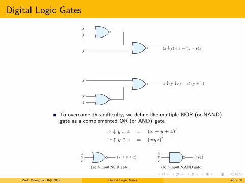
We have to modify the definition of the operation slightlyNAND and NOR operators are not associative
(x ↓ y) ↓ z =[(x+ y)′ + z
]′= (x+ y)z′ = xz′ + yz′
x ↓ (y ↓ z) =[x+ (y + z)′
]′= x′(y + z) = x′y + x′z
Prof. Wangrok Oh(CNU) Digital Logic Gates 39 / 50
Digital Logic GatesSection 2.8 Digital Logic Gates 63
of a three‐input exclusive‐OR function is shown in Fig. 2.8 . This function is normally implemented by cascading two‐input gates, as shown in (a). Graphically, it can be represented with a single three‐input gate, as shown in (b). The truth table in (c) clearly indicates that the output F is equal to 1 if only one input is equal to 1 or if all three inputs are equal to 1 (i.e., when the total number of 1’s in the input variables is odd). (Exclusive‐OR gates are discussed further in Section 3.9.)
Positive and Negative Logic
The binary signal at the inputs and outputs of any gate has one of two values, except during transition. One signal value represents logic 1 and the other logic 0. Since two signal values are assigned to two logic values, there exist two different assignments of
(x y) z ! (x " y)z#
x
y
y
x (y z) ! x# (y " z)x
y
z
FIGURE 2.6Demonstrating the nonassociativity of the NOR operator: (x T y) T z ! x T (y T z)
(a) 3-input NOR gate
y (x " y " z)#x
z
(b) 3-input NAND gate
(xyz)#yx
z
(c) Cascaded NAND gates
D
B
F ! [(ABC)# $ (DE)#]# ! ABC " DE
A
C
E
FIGURE 2.7Multiple‐input and cascaded NOR and NAND gates
To overcome this difficulty, we define the multiple NOR (or NAND)gate as a complemented OR (or AND) gate
x ↓ y ↓ z = (x+ y + z)′
x ↑ y ↑ z = (xyz)′
Section 2.8 Digital Logic Gates 63
of a three‐input exclusive‐OR function is shown in Fig. 2.8 . This function is normally implemented by cascading two‐input gates, as shown in (a). Graphically, it can be represented with a single three‐input gate, as shown in (b). The truth table in (c) clearly indicates that the output F is equal to 1 if only one input is equal to 1 or if all three inputs are equal to 1 (i.e., when the total number of 1’s in the input variables is odd). (Exclusive‐OR gates are discussed further in Section 3.9.)
Positive and Negative Logic
The binary signal at the inputs and outputs of any gate has one of two values, except during transition. One signal value represents logic 1 and the other logic 0. Since two signal values are assigned to two logic values, there exist two different assignments of
(x y) z ! (x " y)z#
x
y
y
x (y z) ! x# (y " z)x
y
z
FIGURE 2.6Demonstrating the nonassociativity of the NOR operator: (x T y) T z ! x T (y T z)
(a) 3-input NOR gate
y (x " y " z)#x
z
(b) 3-input NAND gate
(xyz)#yx
z
(c) Cascaded NAND gates
D
B
F ! [(ABC)# $ (DE)#]# ! ABC " DE
A
C
E
FIGURE 2.7Multiple‐input and cascaded NOR and NAND gates
Prof. Wangrok Oh(CNU) Digital Logic Gates 40 / 50
Digital Logic Gates
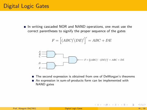
In writing cascaded NOR and NAND operations, one must use thecorrect parentheses to signify the proper sequence of the gates
F =[(ABC)′(DE)′
]′= ABC +DE
Section 2.8 Digital Logic Gates 63
of a three‐input exclusive‐OR function is shown in Fig. 2.8 . This function is normally implemented by cascading two‐input gates, as shown in (a). Graphically, it can be represented with a single three‐input gate, as shown in (b). The truth table in (c) clearly indicates that the output F is equal to 1 if only one input is equal to 1 or if all three inputs are equal to 1 (i.e., when the total number of 1’s in the input variables is odd). (Exclusive‐OR gates are discussed further in Section 3.9.)
Positive and Negative Logic
The binary signal at the inputs and outputs of any gate has one of two values, except during transition. One signal value represents logic 1 and the other logic 0. Since two signal values are assigned to two logic values, there exist two different assignments of
(x y) z ! (x " y)z#
x
y
y
x (y z) ! x# (y " z)x
y
z
FIGURE 2.6Demonstrating the nonassociativity of the NOR operator: (x T y) T z ! x T (y T z)
(a) 3-input NOR gate
y (x " y " z)#x
z
(b) 3-input NAND gate
(xyz)#yx
z
(c) Cascaded NAND gates
D
B
F ! [(ABC)# $ (DE)#]# ! ABC " DE
A
C
E
FIGURE 2.7Multiple‐input and cascaded NOR and NAND gates
The second expression is obtained from one of DeMorgan’s theoremsAn expression in sum-of-products form can be implemented withNAND gates
Prof. Wangrok Oh(CNU) Digital Logic Gates 41 / 50
Digital Logic Gates
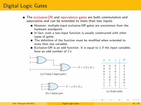
The exclusive-OR and equivalence gates are both commutative andassociative and can be extended to more than two inputs
However, multiple-input exclusive-OR gates are uncommon from thehardware standpointIn fact, even a two-input function is usually constructed with othertypes of gatesThe definition of the function must be modified when extended tomore than two variablesExclusive-OR is an odd function: It is equal to 1 if the input variableshave an odd number of 1’s
64 Chapter 2 Boolean Algebra and Logic Gates
signal level to logic value, as shown in Fig. 2.9 . The higher signal level is designated by H and the lower signal level by L. Choosing the high‐level H to represent logic 1 defines a positive logic system. Choosing the low‐level L to represent logic 1 defines a negative logic system. The terms positive and negative are somewhat misleading, since both sig-nals may be positive or both may be negative. It is not the actual values of the signals that determine the type of logic, but rather the assignment of logic values to the relative amplitudes of the two signal levels.
Hardware digital gates are defined in terms of signal values such as H and L. It is up to the user to decide on a positive or negative logic polarity. Consider, for example, the electronic gate shown in Fig. 2.10 (b). The truth table for this gate is listed in Fig. 2.10 (a). It specifies the physical behavior of the gate when H is 3 V and L is 0 V. The truth table of Fig. 2.10 (c) assumes a positive logic assignment, with H = 1 and L = 0. This truth table is the same as the one for the AND operation. The graphic symbol for a positive logic AND gate is shown in Fig. 2.10 (d).
Now consider the negative logic assignment for the same physical gate with L = 1 and H = 0. The result is the truth table of Fig. 2.10 (e). This table represents the OR operation, even though the entries are reversed. The graphic symbol for the negative‐logic OR gate is shown in Fig. 2.10 (f). The small triangles in the inputs and output
(a) Using 2-input gates
(b) 3-input gate(c) Truth table
xF ! x ! y ! zy
z
y
zF ! x ! y ! z
xx y z F
0
0
00
11
1
1
0
1
10
10
0
1
0
1
01
01
0
1
011
0
0
1
0
1
FIGURE 2.8Three‐input exclusive‐OR gate
(a) Positive logic
Logicvalue
1
0
Signalvalue
H
L(b) Negative logic
Logicvalue
0
1
Signalvalue
H
L
FIGURE 2.9Signal assignment and logic polarity
Prof. Wangrok Oh(CNU) Digital Logic Gates 42 / 50
Digital Logic Gates
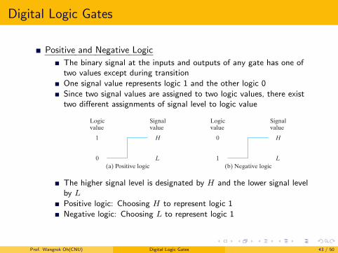
Positive and Negative Logic
The binary signal at the inputs and outputs of any gate has one oftwo values except during transitionOne signal value represents logic 1 and the other logic 0Since two signal values are assigned to two logic values, there existtwo different assignments of signal level to logic value
64 Chapter 2 Boolean Algebra and Logic Gates
signal level to logic value, as shown in Fig. 2.9 . The higher signal level is designated by H and the lower signal level by L. Choosing the high‐level H to represent logic 1 defines a positive logic system. Choosing the low‐level L to represent logic 1 defines a negative logic system. The terms positive and negative are somewhat misleading, since both sig-nals may be positive or both may be negative. It is not the actual values of the signals that determine the type of logic, but rather the assignment of logic values to the relative amplitudes of the two signal levels.
Hardware digital gates are defined in terms of signal values such as H and L. It is up to the user to decide on a positive or negative logic polarity. Consider, for example, the electronic gate shown in Fig. 2.10 (b). The truth table for this gate is listed in Fig. 2.10 (a). It specifies the physical behavior of the gate when H is 3 V and L is 0 V. The truth table of Fig. 2.10 (c) assumes a positive logic assignment, with H = 1 and L = 0. This truth table is the same as the one for the AND operation. The graphic symbol for a positive logic AND gate is shown in Fig. 2.10 (d).
Now consider the negative logic assignment for the same physical gate with L = 1 and H = 0. The result is the truth table of Fig. 2.10 (e). This table represents the OR operation, even though the entries are reversed. The graphic symbol for the negative‐logic OR gate is shown in Fig. 2.10 (f). The small triangles in the inputs and output
(a) Using 2-input gates
(b) 3-input gate(c) Truth table
xF ! x ! y ! zy
z
y
zF ! x ! y ! z
xx y z F
0
0
00
11
1
1
0
1
10
10
0
1
0
1
01
01
0
1
011
0
0
1
0
1
FIGURE 2.8Three‐input exclusive‐OR gate
(a) Positive logic
Logicvalue
1
0
Signalvalue
H
L(b) Negative logic
Logicvalue
0
1
Signalvalue
H
L
FIGURE 2.9Signal assignment and logic polarity
The higher signal level is designated by H and the lower signal levelby L
Positive logic: Choosing H to represent logic 1Negative logic: Choosing L to represent logic 1
Prof. Wangrok Oh(CNU) Digital Logic Gates 43 / 50
Digital Logic GatesSection 2.8 Digital Logic Gates 65
designate a polarity indicator, the presence of which along a terminal signifies that negative logic is assumed for the signal. Thus, the same physical gate can operate either as a positive‐logic AND gate or as a negative‐logic OR gate.
The conversion from positive logic to negative logic and vice versa is essentially an operation that changes 1’s to 0’s and 0’s to 1’s in both the inputs and the output of a gate. Since this operation produces the dual of a function, the change of all ter-minals from one polarity to the other results in taking the dual of the function. The upshot is that all AND operations are converted to OR operations (or graphic sym-bols) and vice versa. In addition, one must not forget to include the polarity‐indicator triangle in the graphic symbols when negative logic is assumed. In this book, we will not use negative logic gates and will assume that all gates operate with a positive logic assignment.
(c) Truth table for positive logic
(e) Truth table for negative logic
(d) Positive logic AND gate
(f) Negative logic OR gate
(b) Gate block diagram
xzDigital
gatey
zxy
zxy
(a) Truth table with H and L
x y z
LLLL L
LLHH
H
HH
x y z
000
0 0
0011
1
11
x y z
111
1 1
1100
0
00
FIGURE 2.10Demonstration of positive and negative logic
Section 2.8 Digital Logic Gates 65
designate a polarity indicator, the presence of which along a terminal signifies that negative logic is assumed for the signal. Thus, the same physical gate can operate either as a positive‐logic AND gate or as a negative‐logic OR gate.
The conversion from positive logic to negative logic and vice versa is essentially an operation that changes 1’s to 0’s and 0’s to 1’s in both the inputs and the output of a gate. Since this operation produces the dual of a function, the change of all ter-minals from one polarity to the other results in taking the dual of the function. The upshot is that all AND operations are converted to OR operations (or graphic sym-bols) and vice versa. In addition, one must not forget to include the polarity‐indicator triangle in the graphic symbols when negative logic is assumed. In this book, we will not use negative logic gates and will assume that all gates operate with a positive logic assignment.
(c) Truth table for positive logic
(e) Truth table for negative logic
(d) Positive logic AND gate
(f) Negative logic OR gate
(b) Gate block diagram
xzDigital
gatey
zxy
zxy
(a) Truth table with H and L
x y z
LLLL L
LLHH
H
HH
x y z
000
0 0
0011
1
11
x y z
111
1 1
1100
0
00
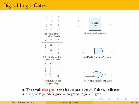
FIGURE 2.10Demonstration of positive and negative logicThe small triangles in the inputs and output: Polarity indicatorPositive-logic AND gate = Negative-logic OR gate
Prof. Wangrok Oh(CNU) Digital Logic Gates 44 / 50
Digital Logic Gates
The conversion from positive logic to negative logic and vice versa isessentially an operation that changes 1’s to 0’s and 0’s to 1’s in bothinputs and output
This operation produces the dual of a function
Prof. Wangrok Oh(CNU) Digital Logic Gates 45 / 50
Integrated Circuits
An integrated circuit (IC) is fabricated on a die of a siliconsemiconductor crystal called a chip containing the electroniccomponents for constructing digital gates
The various gates are interconnected inside the chip to form therequired circuit
The chip is mounted in a ceramic or plastic container andconnections are welded to external pins to form the integrated circuit
Each IC has a numeric designation printed on the surface of thepackage for identification
Vendors provide data books, catalogs, and Internet websites thatcontain descriptions and information about the ICs that theymanufacture
Prof. Wangrok Oh(CNU) Integrated Circuits 46 / 50
Integrated Circuits
Levels of Integration
Small-scale integration (SSI) devices
Contain several independent gates in a single packageThe number of gates is usually fewer than 10
Medium-scale integration (MSI) devices
Have a complexity of approximately 10 to 1,000 gatesThey usually perform specific elementary digital operationsExamples: Decoders, adders, and multiplexers, registers and counters
Large-scale integration (LSI) devices
Contain thousands of gates in a single packageThey include digital systems such as processors, memory chips, andprogrammable logic devices
Very large-scale integration (VLSI) devices
Contain millions of gates within a single packageExamples are large memory arrays and complex microcomputer chipsBecause of their small size and low cost, VLSI devices haverevolutionized the computer system design technology
Prof. Wangrok Oh(CNU) Integrated Circuits 47 / 50
Integrated Circuits
Digital Logic Families
Integrated circuits are classified by the specific circuit technology
The circuit technology is referred to as a digital logic family
Basic circuit in each technology is a NAND, NOR or inverter gateThe most popular logic families
1 TTL: Transistor-transistor logic2 ECL: Emitter-coupled logic3 MOS: Metal-oxide semiconductor4 CMOS: Complementary metal-oxide semiconductor
TTL is a logic family that has been in use for 50 years and isconsidered to be standard
ECL has an advantage in systems requiring high speed operation
MOS is suitable for circuits that need high component density
CMOS is preferable in systems requiring low power consumption
Prof. Wangrok Oh(CNU) Integrated Circuits 48 / 50
Integrated Circuits
The most important parameters distinguishing logic families
Fan-out: Number of standard loads that the output of a typical gatecan drive without impairing its normal operation
Fan-in: number of inputs available in a gate
Power dissipation: power consumed by the gate that must beavailable from the power supply
Propagation delay: average transition delay time for a signal topropagate from input to output
Noise margin: maximum external noise voltage added to an inputsignal that does not cause an undesirable change in the circuit output
Prof. Wangrok Oh(CNU) Integrated Circuits 49 / 50
Integrated Circuits
Computer Aided Design of VLSI Circuits
The design of digital systems with VLSI circuits containing millionsof transistors and gates is an enormous and formidable taskSystems of this complexity are usually impossible to develop andverify without the assistance of computeraided design (CAD) toolsElectronic design automation (EDA) covers all phases of the designof integrated circuitsPhysical realization of a digital circuits
1 Application-specific integrated circuit (ASIC)2 Field-programmable gate array (FPGA)3 Programmable logic device (PLD)4 Full-custom IC
An important development in the design of digital systems is the useof a hardware description language (HDL)
Computer programming language specifically oriented to describingdigital hardwareVerilog and VHDL
Prof. Wangrok Oh(CNU) Integrated Circuits 50 / 50