Embed Size (px)
Citation preview

dat
e: 0
1.18
.13
dra
wn
by: J
Ssc
ale:
not
ed
TITLE
:PR
OJE
CT:
A000
FIVE ATLAS STREETWESTERLY, RI 02891TEL: 401.348.0558FAX: 206.202.2878CELL: 401.218.5791
REV
ISIO
NS:
TITL
E SH
EET
NO
RTHE
RN K
ENTU
CKY
UN
IVER
SITY
BOO
KSTO
REHI
GHL
AN
D H
EIG
HTS,
KY
STO
RE #
803
4
HIGHLAND HEIGHTS, KY 41099NKU Project #NS-39-13
PROJECT LOCATION PROJECT DATA INDEX OF DRAWINGS
VICINITY MAP
COLLEGECAMPUS
1. PROJECT NAME: NORTHERN KENTUCKY UNIVERSITY BOOKSTORE
2. PROJECT DESCRIPTION: TEXTBOOK, STUDENT SUPPLIES, & CLOTHING SALES
3. PROJECT LOCATION: NORTHERN KENTUCKY UNIVERSITY1 NUNN DRIVE, HC BUILDINGHIGHLAND HEIGHTS, KY 41099MANAGER: EMILY CONLEYSTORE NUMBER: 859.572.5142
4. TENANT: BARNES & NOBLE COLLEGE BOOKSELLERS, INC.120 MOUNTAIN VIEW BLVD.BASKING RIDGE, NJ 07920TEL: 908.991.2180CONTACT: RENEE FIELDS
5. LANDLORD/OWNER: NORTHERN KENTUCKY UNIVERSITY1 NUNN DRIVE, HC BUILDINGHIGHLAND HEIGHTS, KY 41099ADMINISTRATIVE CONTACT: CAROLE GIBSONTEL: 859.572.5755
6. TENANT'S STORE PLANNER: IN DESIGNS5 ATLAS STREETWESTERLY, RI 02891TEL: 401.348.0558CONTACT: JOODIE SYMINGTON
7. OCCUPANCY: M (MERCANTILE)
8. GROSS LEASED PREMISES: 7353 S.F. (1ST FL) + 4753 (2ND FL) = 12,106 TOTAL
9. OCCUPANT LOAD: TOTAL NUMBER OF OCCUPANTS: 287SALES FLOOR: 8091 S.F /30 = 270OFFICES: 595 S.F./100 = 6STORAGE: 3285 S.F./300 = 11
10. EXIST REQUIREMENT: FOUR (4) REQ., FOUR (4) PROVIDED
12. MISC. NOTES: JOB IS TO BE NON-UNION
A000 TITLE SHEET
A001 GENERAL NOTES
A100 DEMOLITION/CONSTRUCTION PLAN - 1st FLOOR
A700 NEW STORE ENTRANCE SKETCH - 2nd FLOORA701 NEW PICK-UP WINDOW DETAILS - 1st FLOOR
A101 DEMOLITION/CONSTRUCTION PLAN - 2nd FLOOR
A002 SCHEDULES
A003 EXISTING FIXTURE PLAN - 1st FLOOR
A004 EXISTING FIXTURE PLAN - 2nd FLOOR
A102 NEW FIXTURE PLAN - 1ST FLOOR
A103 NEW FIXTURE PLAN - 2nd FLOOR
A702 FIXTURE DETAILSE001 ELECTRICAL LEGEND AND LUMINAIRE SCHEDULE
E300 ELECTRICAL SINGLE LINE DIAGRAM
ED101 ELECTRICAL DEMOLITION PLAN - 1st FLOORED102 ELECTRICAL DEMOLITION PLAN 2nd FLOOREL101 ELECTRICAL LIGHTING PLAN 1ST FLOOREL102 ELECTRICAL LIGHTING PLAN 2nd FLOOREP101 ELECTRICAL POWER PLAN 1st FLOOREP102 ELECTRICAL POWER PLAN 2nd FLOOR
BOOKSTORE
E500 ELECTRICAL SPECIFICATIONS

dat
e: 0
1.18
.13
dra
wn
by: J
Ssc
ale:
not
ed
TITLE
:PR
OJE
CT:
A001
FIVE ATLAS STREETWESTERLY, RI 02891TEL: 401.348.0558FAX: 206.202.2878CELL: 401.218.5791
REV
ISIO
NS:
GEN
ERA
L N
OTE
SN
ORT
HERN
KEN
TUC
KY U
NIV
ERSI
TYBO
OKS
TORE
HIG
HLA
ND
HEI
GHT
S, K
YST
ORE
# 8
034
DIVISION 1 - GENERAL REQUIREMENTS
DIVISION 2 - DEMOLITION / BUILDING ALTERATIONS
DIVISION 3 - NOT USED
DIVISION 4 - NOT USED
DIVISION 5 - NOT USED
DIVISION 6- WOOD & PLASTICS
DIVISION 7 - SEALANT AND CAULKING
DIVISION 8 - WOOD & HOLLOW METAL DOORS & FRAMES
HARDWARE
DIVISION 9 - FINISHES
CARPET
RESILIENT BASE
PAINT
DIVISION 10 - SPECIALTIES
LOCKERS
SIGNS
FIRE EXTINGUISHERS (PROVIDED BY G.C.)
DIVISION 11 - EQUIPMENT - AUDIO/VISUAL
DIVISION 16 - ELECTRICAL
ABBREVIATIONS
SYMBOLS
N
1
101
CEILINGS
1
101
X
A
B
C
D
E
F
G
H
I
M
N
O
P
Q
R
S
T
U
V
WL

FIXTURE SCHEDULE
FIXTURE
CODES
DESCRIPTION MFG/SUPPLIER FINISHES DETAILS
CLOTHING & GIFTS
DIV-T3 SET OF (3) STAINED WOOD
NESTING TABLES
WOODIN STAIN: MAPLE
CL-3 4-WAY WOODIN CHROME
CL-4 2-WAY WOODIN CHROME
CL-8 SLATWALL GARCY/WOODIN SLATS: L1
INSERTS: L1
TRIM: L1
ACCESSORIES: CHROME
TSHIRT T-SHIRT CUBBIES WOODIN/WOODIN L1
MANQ MANNEQUIN WOODIN STANDARD
ACCESS ACCESSORIES WOODIN CHROME SUPPLY ALL NEW CHROME
ACCESSORIES FOR EXISTING
FOLLET SLATWALL SYSTEM
CHECK OUT
CS DESK CUSTOMER SERVICE DESK WOODIN/WOODIN COUNTER: L2
ENDPANELS L1
INTERIOR: ALMOND
CO-10 COUNTER WOODIN/WOODIN L2 WITH STORAGE BELOW
CROWD TENSA BARRIERS WOODIN/WOODIN STANDARD STANDS
TAPE: BLACK
INFORMATION CENTER
INFO INFORMATION CENTER WOODIN/WOODIN COUNTER: L2
VERTICAL: L1
INTERIOR ALMOND
10' X 10'
STOCKROOM
ST-1 STOCKROOM COUNTER WOODIN/WOODIN STANDARD
STW-1 BACKROOM STORAGE WOODIN/WOODIN STANDARD 18"D X 84"H
STW-1SP BACKROOM STORAGE WOODIN/WOODIN STANDARD 12"D X 84"H
HANG HANG RODS
DOUBLE HUNG
WOODIN/WOODIN STANDARD
FURNITURE
C-1 LOUNGE CHAIR
WHITEHALL SOLSTICE
BCI FINISH: CLEAR MAPLE
FABRIC: BRISA, BLACK
ONYX
T-1 SQUARE TABLE
LOWENSTEIN ASTORIA
BCI FINISH: NATURAL MAPLE
T-2 RECTANGLE TABLE
LOWENSTEIN ASTORIA
BCI FINISH: NATURAL MAPLE
FIXTURE FINISHES
L1 WILSONART KENSINGTON MAPLE
L2 WILSONART OILED SOAPSTONE
FIXTURE NOTES
1 COLOR OF STEEL: HQ1
2
STEEL IS FOLLET FIXTURES
3 EXISTING WALL: N/A
4 EXISTING GONDOLAS: N/A
5 PERIMETER WALL ARE DRYWALL.
dat
e: 0
1.18
.13
dra
wn
by: J
Ssc
ale:
not
ed
TITLE
:PR
OJE
CT:
A002
FIVE ATLAS STREETWESTERLY, RI 02891TEL: 401.348.0558FAX: 206.202.2878CELL: 401.218.5791
REV
ISIO
NS:
SCHE
DULE
SN
ORT
HERN
KEN
TUC
KY U
NIV
ERSI
TYBO
OKS
TORE
HIG
HLA
ND
HEI
GHT
S, K
YST
ORE
# 8
034

UP
UP
UTILITY CORRIDOR
UP
ELECTRIC ROOM
LOBBY
UNIVERSITY CENTER
UNIVERSITY CENTER ELEVATION
849.94'
PROCESSING
9.4
BOOKSTORE
STORAGE
9.5CORRIDOR
UC155H
UC155
UC161
UC160H
UC163
162
UC199W
UC160B
UC160A
UC160E
UC170
UC169
UC100E
UC150
UC146
UC144
UC143
UC199C
UC142
STAIR
ELEV.
UC161A
10
EMERGENCY EXIT CORRIDOR
POST-OFFICE
SERVICE COUNTER
OFFICE
ELECT.
UNIVERSITY
STORAGE
STORAGE
UTILITY CORRIDOR
72
"h
72
"h
72
"h
72
"h
72
"h
72
"h
72
"h
72
"h
72
"h
72
"h
72
"h
UP
STORE
MANAGER
9.3
EMPLOYEE
BREAKROOM
9.2
TEXTBOOK
MANAGER
CASH
ROOM
72
"h
72
"h
72
"h
dat
e: 0
1.18
.13
dra
wn
by: J
Ssc
ale:
not
ed
TITLE
:PR
OJE
CT:
A003
FIVE ATLAS STREETWESTERLY, RI 02891TEL: 401.348.0558FAX: 206.202.2878CELL: 401.218.5791
REV
ISIO
NS:
EXIS
TIN
G F
IXTU
RE P
LAN
FIRS
T FLO
OR
NO
RTHE
RN K
ENTU
CKY
UN
IVER
SITY
BOO
KSTO
REHI
GHL
AN
D H
EIG
HTS,
KY
STO
RE #
803
4
N
1/8" = 1'-0"
FIRST FLOOR0 2 4 8
FIXTURE INVENTORY PREFORMED ON 10.23.12

MAIN LOBBY
ATRIUM
UNIVERSITY CENTER
WOMEN
MEN
MECHANICAL
JAN.
STAIR
PASSENGER
ELEV
ENTRANCE
CORRIDOR
CORRIDOR
DN UP
THEATER
ELE
STORAGE
DN
UP
DN
OPEN TO BELOW
OPEN TO BELOW
STAIR
SERVICE
CORRIDOR
UC260
UC299W
UC260E
UC260S
UC260B
UC260A
UC270
UC260H
UC256
UC265
UC266
UC255
UC255H
UC200E
UC299B
UC256H UC250
UC299A
26
0
255H
NO
ARCHITECTURAL
WORK
OFFICE
260A
CU
ST
OM
ER
S
ER
VIC
E
CLOTHING
CLOTHING
CLOTHING
CLOTHING
GIFTS
CLOTHING CLOTHING
CLOTHING
CH
EC
KP
OIN
T
CHECKPOINT
CO
MP
UT
ER
PE
RIP
HE
RA
LS
dat
e: 0
1.18
.13
dra
wn
by: J
Ssc
ale:
not
ed
TITLE
:PR
OJE
CT:
A004
FIVE ATLAS STREETWESTERLY, RI 02891TEL: 401.348.0558FAX: 206.202.2878CELL: 401.218.5791
REV
ISIO
NS:
EXIS
TIN
G F
IXTU
RE P
LAN
SEC
ON
D F
LOO
R
NO
RTHE
RN K
ENTU
CKY
UN
IVER
SITY
BOO
KSTO
REHI
GHL
AN
D H
EIG
HTS,
KY
STO
RE #
803
4
N
1/8" = 1'-0"
SECOND FLOOR0 2 4 8
FIXTURE INVENTORY PREFORMED ON 10.23.12

UP
UP
UTILITY CORRIDOR
UP
ELECTRIC ROOM
LOBBY
UNIVERSITY CENTER
UNIVERSITY CENTER ELEVATION
849.94'
STORE
MANAGER
9.3
EMPLOYEE
BREAKROOM
9.2
STORAGE
9.4
BOOKSTORE
STORAGE
9.5
CORRIDOR
UC155H
UC155
UC161
UC160H
UC163
162
UC199W
UC160B
UC160A
UC160E
UC170
UC169
UC100E
UC150UC146
UC144
UC143UC199C
UC142
TEXTBOOK
MANAGER
CASH
ROOM
STAIR
ELEV.
UC161A
10
EMERGENCY EXIT CORRIDOR
POST-OFFICE
SERVICE COUNTER
STORAGE
ELECT.
PROCESSING
STORAGE
UTILITY CORRIDOR
UP
6'
N.I.C.
N.I.C.
N.I.C.
N.I.C.
N.I.C.
N.I.C.
D1
2'
D3
N.I.C.
6'
D2
D6
D7
D8
D9
1'-8"
D4
D5
D10
D3
D1
DEMO/CONSTRUCTION NOTES
LEGEND
Existing Partition to Remain
Demolition
New Full Ht. Partition
D2
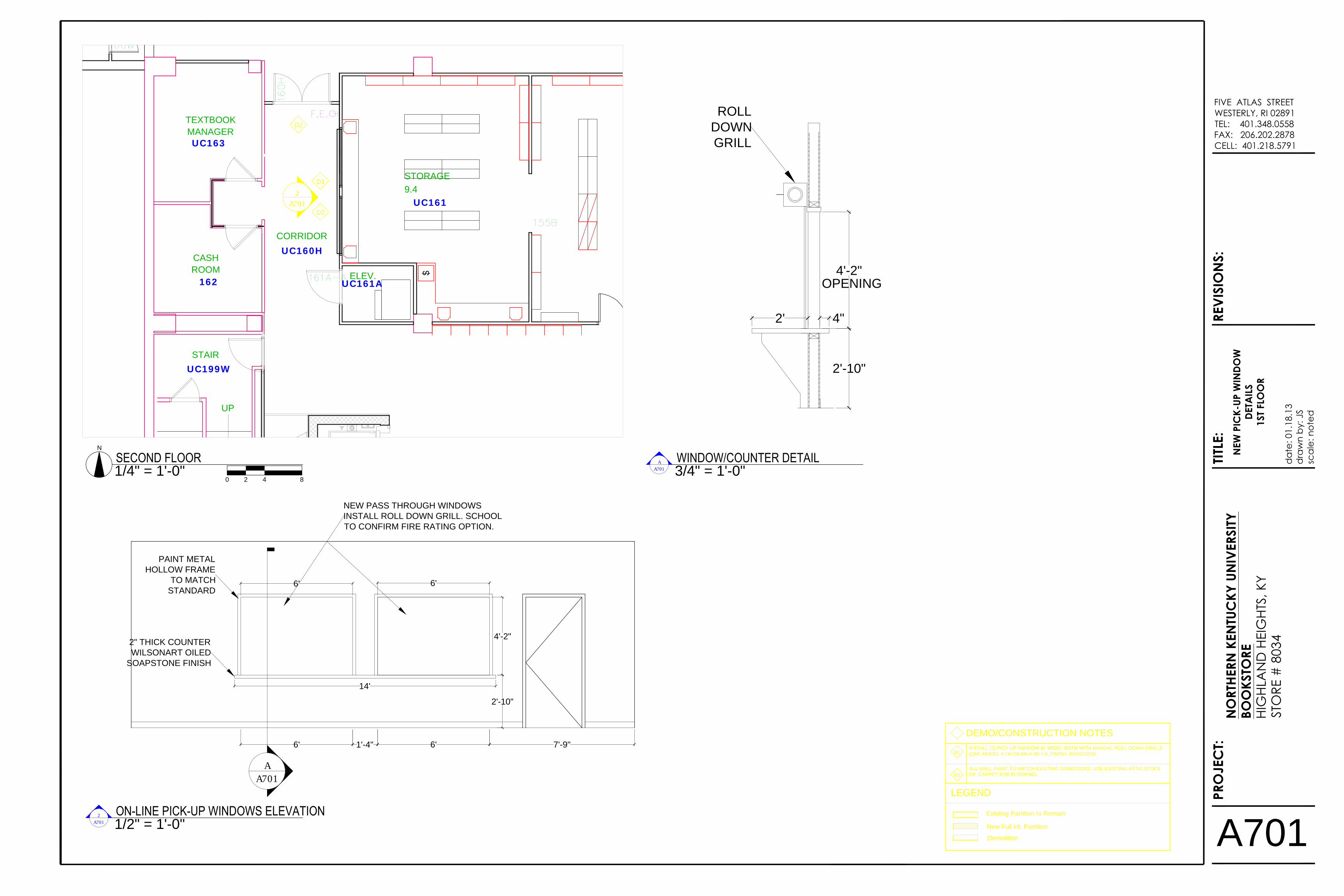
INSTALL OPENING IN WALL. LEAVE HEADER 7' A.F.F.
D3
INSTALL (2) PICK-UP WINDOW (6' WIDE). BOTH WITH MANUAL ROLL DOWN GRILLS
(QMI, MODEL # 1M-GEAR-A-08-7-9). INSTALL COUNTER AND POWER/DATA.
REFER TO A700 FOR DETAILS.
D4
REMOVE EXISTING SIGN. PATCH AND REPAINT WALLS AROUND ELEVATOR AND
SOFFIT. PAINT COLOR SHERWIN WILLIAMS PRO MAR 200, 6906 CITRUS, FINISH:
EGG SHELL.
D5
REMOVE EXISTING BOOK INFORMATION DESK AND WALL PANELING. USE ATTIC
STOCK OF EXISTING CARPET IF NEEDED.
INSTALL NEW DOUBLE 3'-0" X 7'-0 SOLID DOOR AND DOOR FRAME. MATCH
BUILDING STANDARDS FOR DOORS AND FRAMES.
HARDWARE:
HINGES: (3) PER DOOR HAGER BB1279 (4-1/2" X 4-1/2")
DIGITAL LOCKSET: SCHLAGE CO-100 OFF LINE ELECTRONIC LOCK
CLOSER: CORBIN-RUSSWIN 3210
FLUSH BOLTS: IVES FB61P
KICK PLATES: (2) PER DOOR ROCKWOOD K2062 8" X 34" HEAVY DUTY
WALL STOPS: ROCKWOOD 409 OR EQUAL
REMOVE DOORS. FRAME TO REMAIN.
D6
INSTALL NEW DOOR FOR ROOM 150. SCHOOL TO SPECIFY DOOR AND
HARDWARE NEEDED FOR SPACE.
D7
DOOR TO REMAIN LOCKED. NO ACCESS ALLOWED FROM ROOM 150 TO ROOM
143.
D8
DRYWALL AND DOOR WITH FRAME TO BE MOVED AS SHOWN.
D9
REPLACE ANY CARPET TILES THAT ARE STAINED WITH ATTIC STOCK, FIRST AND
SECOND FLOOR.
D10
dat
e: 0
1.18
.13
dra
wn
by: J
Ssc
ale:
not
ed
TITLE
:PR
OJE
CT:
A100
FIVE ATLAS STREETWESTERLY, RI 02891TEL: 401.348.0558FAX: 206.202.2878CELL: 401.218.5791
REV
ISIO
NS:
DEM
OLI
TION
/C
ON
STRU
CTIO
N P
LAN
FIRS
T FLO
OR
NO
RTHE
RN K
ENTU
CKY
UN
IVER
SITY
BOO
KSTO
REHI
GHL
AN
D H
EIG
HTS,
KY
STO
RE #
803
4
N
1/8" = 1'-0"
FIRST FLOOR0 2 4 8
A701

MAIN LOBBY
ATRIUM
UNIVERSITY CENTER
WOMEN
MEN
MECHANICAL
JAN.
STAIR
PASSENGER
ELEV
ENTRANCE
CORRIDOR
CORRIDOR
DN UP
THEATER
ELE
STORAGE
DN
UP
DN
OPEN TO BELOW
OPEN TO BELOW
STAIR
SERVICE
CORRIDOR
UC299W
UC260E
UC260S
UC260B
UC260A
UC270
UC260H
UC256
UC265
UC266
UC255
UC255H
UC200E
UC299B
UC256H UC250
UC299A2
60
255H
OFFICE
260A
D1
D2
D3
D4
N.I.C.
N.I.C.
N.I.C.
N.I.C.
N.I.C.
N.I.C.
N.I.C.
N.I.C.
N.I.C.
N.I.C.
N.I.C.
N.I.C.
N.I.C.
N.I.C.
N.I.C.
D6
D2
D7
D8
D9
REMOVE CHECKPOINT ANTENNAS.D1
DEMO/CONSTRUCTION NOTES
LEGEND
Existing Partition to Remain
Demolition
New Full Ht. Partition
DOORS WILL REMAIN AND LOCKED AT ALL TIMES.
D2
REMOVE AND DISCARD EXISTING CASHWRAP.
D3
D4
NEW GLASS STORE FRONT WITH SIDELIGHTS WITH NEW FLOORING AND
BOOKSTORE SIGN. REMOVE CHECKPOINT AND NEW FLOORING. DETAILS ON
A700.
D5
NOT USED
D6
REMOVE EXISTING COUNTER IN OFFICE.
D7
REMOVE SLATWALL. PATCH AND PAINT WALL TO MATCH EXISTING.
D8
REPLACE ANY CARPET TILES THAT ARE STAINED WITH ATTIC STOCK, FIRST AND
SECOND FLOOR.
D9
PAINT ELEVATOR WALLS SHERWIN WILLIAMS PRO MAR 200, 6906 CITRUS, EGG
SHELL FINISH.
dat
e: 0
1.18
.13
dra
wn
by: J
Ssc
ale:
not
ed
TITLE
:PR
OJE
CT:
A101
FIVE ATLAS STREETWESTERLY, RI 02891TEL: 401.348.0558FAX: 206.202.2878CELL: 401.218.5791
REV
ISIO
NS:
DEM
OLI
TION
PLA
NSE
CO
ND
FLO
OR
NO
RTHE
RN K
ENTU
CKY
UN
IVER
SITY
BOO
KSTO
REHI
GHL
AN
D H
EIG
HTS,
KY
STO
RE #
N
1/8" = 1'-0"
SECOND FLOOR0 4 8 16
A700

UP
UP
UTILITY CORRIDOR
UP
ELECTRIC ROOM
LOBBY
UNIVERSITY CENTER
UNIVERSITY CENTER ELEVATION
849.94'
STORE
MANAGER
9.3
EMPLOYEE
BREAKROOM
9.2
STORAGE
9.4
BOOKSTORE
STORAGE
9.5
CORRIDOR
UC155H
UC155
UC161
UC160H
UC163
162
UC199W
UC160B
UC160A
UC160E
UC170
UC169
UC100E
UC150UC146
UC144
UC143UC199C
UC142
TEXTBOOK
MANAGER
CASH
ROOM
STAIR
ELEV.
UC161A
10
EMERGENCY EXIT CORRIDOR
POST-OFFICE
SERVICE COUNTER
STORAGE
ELECT.
PROCESSING
STORAGE
UTILITY CORRIDOR
72"h
72"h
72"h
UP
NE
W P
RO
CE
SS
IN
G C
OU
NT
ER
NE
W H
AN
G B
AR
S
NEW STORAGE SHELVES
(ACCOMMODATES 3936 BAGS)
N.I.C.
N.I.C.
N.I.C.
N.I.C.
N.I.C.
N.I.C.
F2
NEW INFO DESK
72
"h
72
"h
72
"h
72
"h
72
"h
72
"h
72
"h
72
"h
REUSE EXISTING
SHELVING
N.I.C.
16'
F2
F2
F1
2'
10'
4'-4"
2'12'
ST-1
CO
-1
0
STW-1SP
STW-1SP
STW-1SP
STW-1SP STW-1SP
STW-1SP
STW-1SP
ST
W-1
SP
ST
W-1
SP
ST
W-1
SP
ST
W-1
SP
ST
W-1
SP
ST
W-1
SP
ST
W-1
SP
ST
W-1
SP
ST
W-1
SP
ST
W-1
SP
ST
W-1
HA
NG
TEXTBOOKS
TEXTBOOKS
TEXTBOOKS
TEXTBOOKS
TEXTBOOKS
TEXTBOOKS
TEXTBOOKS
TE
XT
BO
OK
S
TE
XT
BO
OK
S
TE
XT
BO
OK
S
TE
XT
BO
OK
S
TE
XT
BO
OK
S
TE
XT
BO
OK
S
TE
XT
BO
OK
S
CL-8
6'
ST
-1
INFO
(BN CONTRACTOR) INSTALL NEW INFORMATION DESK. (NKU GC) NEW POWER &
DATA TO BE INSTALLED THROUGH NEW POWER POLE.
F1
FIXTURE NOTES
LEGEND
Existing Partition to Remain
Demolition
New Full Ht. Partition
REMOVE ALL EXISTING SHELVING AND COUNTERS. INSTALL ALL NEW SHELVING
AND COUNTERS. INSTALL NEW POWER AND DATA AT COUNTERS.
F2
EXISTING FIXTURES (RELOCATED)
3' WIDE FIXTURE
NEW FIXTURES
FIXTURE KEY
PC OR AS400 TERMINAL
POS TERMINAL
OR
PRINTER
TELEPHONE
UP
UP
UTILITY CORRIDOR
UNIVERSITY CENTER
UNIVERSITY CENTER ELEVATION
849.94'
STORE
MANAGER
9.3
EMPLOYEE
BREAKROOM
9.2
STORAGE
9.4
BOOKSTORE
STORAGE
9.5
CORRIDOR
UC155H
UC155
UC161
UC160H
UC163
162
UC199W
UC160B
UC160A
UC160E
UC170
UC169
UC100E
UC150UC146
UC143
TEXTBOOK
MANAGER
CASH
ROOM
STAIR
ELEV.
UC161A
EMERGENCY EXIT CORRIDOR
POST-OFFICE
SERVICE COUNTER
STORAGE
ELECT.
PROCESSING
STORAGE
72"h
72"h
72"h
UP
NE
W P
RO
CE
SS
IN
G C
OU
NT
ER
NE
W H
AN
G B
AR
S
NEW STORAGE SHELVES
(ACCOMMODATES 3936 BAGS)
N.I.C.
N.I.C.
N.I.C.
F2
2
A701
NEW INFO DESK
72"h
72"h
72"h
72"h
72"h
72"h
72"h
72"h
REUSE EXISTING
SHELVING
PALLET PATHWAY
N.I.C.
16'
F2
F2
F1
2'
10'
4'-4"
2'
12'
ST-1
CO
-10
STW-1SP
STW-1SP
STW-1SP
STW-1SP STW-1SP
STW-1SP
STW-1SP
ST
W-1S
P
ST
W-1S
P
ST
W-1S
P
ST
W-1S
P
ST
W-1S
P
ST
W-1S
P
ST
W-1S
P
ST
W-1S
P
ST
W-1S
P
ST
W-1S
P
ST
W-1
HA
NG
TEXTBOOKS
TEXTBOOKS
TEXTBOOKS
TEXTBOOKS
TEXTBOOKS
TEXTBOOKS
TEXTBOOKS
TE
XT
BO
OK
S
TE
XT
BO
OK
S
TE
XT
BO
OK
S
TE
XT
BO
OK
S
TE
XT
BO
OK
S
TE
XT
BO
OK
S
TE
XT
BO
OK
S
CL-8
6'
ST
-1
INFO
D1
D2
D2
UP
UP
UTILITY CORRIDOR
UNIVERSITY CENTER
UNIVERSITY CENTER ELEVATION
849.94'
STORE
MANAGER
9.3
EMPLOYEE
BREAKROOM
9.2
STORAGE
9.4
BOOKSTORE
STORAGE
9.5
CORRIDOR
UC155H
UC155
UC161
UC160H
UC163
162
UC199W
UC160B
UC160A
UC160E
UC170
UC169
UC100E
UC150UC146
UC144
UC143
TEXTBOOK
MANAGER
CASH
ROOM
STAIR
ELEV.
UC161A
EMERGENCY EXIT CORRIDOR
POST-OFFICE
SERVICE COUNTER
STORAGE
ELECT.
PROCESSING
STORAGE
72"h
72"h
72"h
UP
EX
IS
TIN
G
PR
OC
ES
SIN
G C
OU
NT
ER
.
NE
W H
AN
G B
AR
S
NEW STORAGE SHELVES
(ACCOMMODATES 3500 BAGS)
NE
W S
TO
RA
GE
S
HE
LV
ES
N.I.C.
N.I.C.
N.I.C.
N.I.C.
NEW INFO DESK
72"h
72"h
72"h
72"h
72"h
72"h
72"h
72"h
wire
(4) pc
existing data
(2) ports
reuse existing shelving
wire
(3) PC,
PHONE,
(4)
QUAD
4'
dat
e: 0
1.18
.13
dra
wn
by: J
Ssc
ale:
not
ed
TITLE
:PR
OJE
CT:
A102
FIVE ATLAS STREETWESTERLY, RI 02891TEL: 401.348.0558FAX: 206.202.2878CELL: 401.218.5791
REV
ISIO
NS:
NEW
FIX
TURE
PLA
NFI
RST F
LOO
R
NO
RTHE
RN K
ENTU
CKY
UN
IVER
SITY
BOO
KSTO
REHI
GHL
AN
D H
EIG
HTS,
KY
STO
RE #
803
4
N
1/8" = 1'-0"
FIRST FLOOR0 2 4 8
1/16" = 1'-0"
TRAFFIC FLOW PLAN1/16" = 1'-0"
BUYBACK PLAN

MAIN LOBBY
ATRIUM
UNIVERSITY CENTER
WOMEN
MEN
MECHANICAL
JAN.
STAIR
PASSENGER
ELEV
ENTRANCE
CORRIDOR
CORRIDOR
DN UP
THEATER
ELE
STORAGE
DN
UP
DN
OPEN TO BELOW
OPEN TO BELOW
STAIR
SERVICE
CORRIDOR
UC299W
UC260E
UC260S
UC260B
UC260A
UC270
UC260H
UC256
UC265
UC266
UC255
UC255H
UC200E
UC299B
UC256H UC250
UC299A2
60
255H
OFFICE
260A
CLOTHING
CLOTHING
GIFTS
CLOTHING
CLOTHING
TSHIRT CUBBIE
CO
MP
UT
ER
PE
RIP
HE
RA
LS
GE
NE
RA
L R
EA
DIN
G
LA
W B
OO
KS
SCHOOL SUPPLIES
SCHOOL SUPPLIES
ELECTRONICS
ELECTRONICS
BIN
DE
RS
BA
CK
PA
CK
S
NOTEBOOKS
LAW
DEPARTMENT
NOOK/TECH
CABINET
5'
3'-0
1
2
"
N.I.C.
N.I.C.
N.I.C.
N.I.C.
N.I.C.
N.I.C.
N.I.C.
N.I.C.
N.I.C.
N.I.C.
N.I.C.
N.I.C.
N.I.C.
N.I.C.
N.I.C.
SEATING
SEATING
SEATING
4'
CL-3 CL-3 CL-3 CL-3
CL-3CL-3CL-3CL-3CL-3CL-3
CL-3 CL-3
CL-3 CL-3 CL-3
CL-3
DIV-T3
TSHIRT
CO-5
CO
-5
C-1 C-1
C-1 C-1
T-1
C-1C-1
T-2
MANQ
MANQ
F1
F2
F3
F4
ACCESS
ACCESS
ACCESS
AC
CE
SS
CL-3 CL-3
CL-3
CL-3
F1
FIXTURE NOTES
EXISTING FIXTURES (RELOCATED)
3' WIDE FIXTURE
NEW FIXTURES
FIXTURE KEY
PC OR AS400 TERMINAL
POS TERMINAL
OR
PRINTER
TELEPHONE
X
INDICATES FIXTURE NUMBER
COINCIDES WITH REUSED FIXTURE FROM EXISTING FIXTURE PLAN
XXX
NEW FIXTURE TAG
F2
(B&N CONTRACTOR) INSTALL NEW CASHWRAP AS SHOWN. NEW POWER AND
DATA WILL BE NEEDED FOR EQUIPMENT HOOK-UP BY NKU GC.
F3
(B&N CONTRACTOR) INSTALL CASHWRAP AS SHOWN . NEW POWER AND DATE
TO BE INSTALLED. INSTALL (2) ADDITIONAL POWER/DATA PORTS FOR FUTURE
USE.
F4
(BN CONTRACTOR) MOVE EXISTING NOOK/TECH. CABINET TO NEW LOCATION
AS SHOWN. (NKU GC) INSTALL POWER IN CEILING AND CONNECT TO EXISTING
PIPE IN FIXTURE. NEW SIGN HOLDER TO BE INSTALLED ON POLE.
REMOVE EXISTING COUNTER IN OFFICE. INSTALL DOUBLE HANG RODS.
dat
e: 0
1.18
.13
dra
wn
by: J
Ssc
ale:
not
ed
TITLE
:PR
OJE
CT:
A103
FIVE ATLAS STREETWESTERLY, RI 02891TEL: 401.348.0558FAX: 206.202.2878CELL: 401.218.5791
REV
ISIO
NS:
NEW
FIX
TURE
PLA
NSE
CO
ND
FLO
OR
NO
RTHE
RN K
ENTU
CKY
UN
IVER
SITY
BOO
KSTO
REHI
GHL
AN
D H
EIG
HTS,
KY
STO
RE #
803
4
01.2
5.13
1
N
1/8" = 1'-0"
SECOND FLOOR0 4 8 16

ATRIUM
STAIR
ENTRANCE
CORRIDOR
DN
UC299B
UC256H UC250N.I.C.
N.I.C.
N.I.C.
N.I.C.
3'-5"3'-5"
7'-7"
6'
(LOGO
SIGN)
(DRYWALL)
(EXISTING
DOORS)
NEW GLASS DOORS AND SIDELIGHTS
MATCH EXISTING @ CLASSROOM UC204
2'-11
1
2
" 2'-3"
6" LETTERING TO MATCH
EXIST @ BUDIG THEATRE
FONT IS TO MATCH EXIST
HELVETICA REGULAR
(WOOD VALANCE)
(EXISTING CONCRETE)
13'-7
1
2
"
2'
8'-5"
Ø2'-10"
GL-5 GL-5GL-5 GL-5
TOP OF
DRYWALL
TO BOTTOM
OF EXIST
CONCRETE
EQEQ
C
L
NEW WING
WALL
STAIR
ENTRANCE
CORRIDOR
UC299B
UC256H
(3) 4' FLUOR
LIGHTS
CEILING
TILE
RECESSED HI HATS
1'
13'-7
1
2
"
D4
3' 2'-6"
D2
WOOD
VALANCE
LOGO
SIGN
EXIST CONC
BEAM ABOVE
NEW WING WALL
ATRIUM
STAIR
ENTRANCE
CORRIDOR
DN
UC299B
UC256H UC250N.I.C.
N.I.C.
N.I.C.
N.I.C.
1
A700
3'
ALIGN CARPET
3'-6"
2'-6"
3'-6"
D1
D2
D3
2'-11
1
2
"
D1
DEMO/CONSTRUCTION NOTES
LEGEND
Existing Partition to Remain
Demolition
New Full Ht. Partition
D2
D4
PROVIDE AND INSTALL NEW GLASS STORE FRONT WITH SIDELIGHTS TO MATCH
EXISTING UC204 CLASSROOM. THE GLASS IS TO BE GL-5 INCLUDING THE
SURROUNDING TRANSOM/SIDELITES.
PROVIDE AND INSTALL NEW FLOORING AS SHOWN. NEW FLOORING TO BE
MATS, INC., WALK OFF MAT TILES, MI CARPET MATTING 9800, COLOR BLACK OR
EQUAL. PROVIDE APPROPRIATE FLOOR TRANSITIONS.
D3
(REMOVE EXISTING CHECKPOINT ANTENNAS.
PROVIDE AND INSTALL VALANCE AND BOOKSTORE SIGN. SIGN TO MATCH FINISH
AND FONT AS EXISTING SIGNAGE IN LOBBY.
GLAZING TYPE KEY:
MONOTLOTHIC FLOAT-GLASSGL-5
dat
e: 0
1.18
.13
dra
wn
by: J
Ssc
ale:
not
ed
TITLE
:PR
OJE
CT:
A700
FIVE ATLAS STREETWESTERLY, RI 02891TEL: 401.348.0558FAX: 206.202.2878CELL: 401.218.5791
REV
ISIO
NS:
NEW
STO
RE E
NTR
AN
CE
SKET
CH
NO
RTHE
RN K
ENTU
CKY
UN
IVER
SITY
BOO
KSTO
REHI
GHL
AN
D H
EIG
HTS,
KY
STO
RE #
803
4
N
1/4" = 1'-0"
DEMOLITION PLAN0 2 4 8
1/2" = 1'-0"
DOOR ELEVATION1/4" = 1'-0"
CEILING PLAN1
A700
1/4" = 1'-0"
CONSTRUCTION PLAN
UP
STORAGE
9.4
CORRIDOR
UC161
UC160H
UC163
162
UC199W
TEXTBOOK
MANAGER
CASH
ROOM
STAIR
ELEV.
UC161A
2
A701
D1
D2
D2
7'-9"6'1'-4"6'
6'
4'-2"
6'
14'
NEW PASS THROUGH WINDOWS
INSTALL ROLL DOWN GRILL. SCHOOL
TO CONFIRM FIRE RATING OPTION.
A
A701
2" THICK COUNTER
WILSONART OILED
SOAPSTONE FINISH
PAINT METAL
HOLLOW FRAME
TO MATCH
STANDARD
2'-10"
2' 4"
4'-2"
OPENING
2'-10"
ROLL
DOWN
GRILL
D1
DEMO/CONSTRUCTION NOTES
LEGEND
Existing Partition to Remain
Demolition
New Full Ht. Partition
INSTALL (2) PICK-UP WINDOW (6' WIDE). BOTH WITH MANUAL ROLL DOWN GRILLS
(QMI, MODEL # 1M-GEAR-A-08-7-9, FINISH: ANODIZED).
D2
ALL WALL PAINT TO MATCH EXISTING CONDITIONS. USE EXISTING ATTIC STOCK
OF CARPET FOR FLOORING.
dat
e: 0
1.18
.13
dra
wn
by: J
Ssc
ale:
not
ed
TITLE
:PR
OJE
CT:
A701
FIVE ATLAS STREETWESTERLY, RI 02891TEL: 401.348.0558FAX: 206.202.2878CELL: 401.218.5791
REV
ISIO
NS:
NEW
PIC
K-UP
WIN
DOW
DETA
ILS
1ST F
LOO
R
NO
RTHE
RN K
ENTU
CKY
UN
IVER
SITY
BOO
KSTO
REHI
GHL
AN
D H
EIG
HTS,
KY
STO
RE #
803
4
N
1/4" = 1'-0"
SECOND FLOOR0 2 4 8
1/2" = 1'-0"
ON-LINE PICK-UP WINDOWS ELEVATION
3/4" = 1'-0"
WINDOW/COUNTER DETAIL
2
A701
A
A701

10'-4"
2'-10"
5'-2"
1'-5"
3'-2"
3'
1'-9"
6"
2'-3"
7'
1'-3"
2'-10"
10'
10'
5'
3'
2'-5"
3'-6"
91
1
4
"
4'
1'-4"
4'
2'-6"
dat
e: 0
1.18
.13
dra
wn
by: J
Ssc
ale:
not
ed
TITLE
:PR
OJE
CT:
A702
FIVE ATLAS STREETWESTERLY, RI 02891TEL: 401.348.0558FAX: 206.202.2878CELL: 401.218.5791
REV
ISIO
NS:
FIXT
URE
DETA
ILS
NO
RTHE
RN K
ENTU
CKY
UN
IVER
SITY
BOO
KSTO
REHI
GHL
AN
D H
EIG
HTS,
KY
STO
RE #
803
4
1/4" = 1'-0"
CUSTOMER SERVICE DESK
FRONT VIEW
PLAN VIEW
1/4" = 1'-0"
CUSTOMER SERVICE DESK
FRONT VIEW
PLAN VIEW
1/4" = 1'-0"
INFORMATION DESK
FRONT VIEW
PLAN VIEW
1/4" = 1'-0"
TSHIRT CUBBIE1/4" = 1'-0"
DIV-T3

DA
TE:
04.1
9.13
DRA
WN
BY:
SN
FSC
ALE
: N
OTE
D
TITLE
:PR
OJE
CT:
FIVE ATLAS STREETWESTERLY, RI 02891TEL: 401.348.0558FAX: 206.202.2878CELL: 401.218.5791
REVI
SIO
NS:
NO
RTHE
RN K
ENTU
CKY
UN
IVER
SITY
BOO
KSTO
REHI
GHL
AN
D H
EIG
HTS,
KY
STO
RE #
803
4
E001
SCALE: N.T.S.ELECTRICAL LEGEND AND LUMINAIRE SCHEDULE
ELEC
TRIC
AL
LEG
END
AN
DLU
MIN
AIR
ESC
HEDU
LE

10
UP
UP
UTILITY CORRIDOR
UP
ELECTRIC ROOM
LOBBY
UNIVERSITY CENTER
STORE
MANAGER
9.3
EMPLOYEE
BREAKROOM
9.2
STORAGE
9.4
BOOKSTORE
STORAGE
9.5
CORRIDOR
UC155H
UC155
UC161
UC160H
UC163
162
UC199W
UC160B
UC160A
UC160E
UC170
UC169
UC100E
UC150
UC146
UC144
UC143
UC199C
UC142
TEXTBOOK
MANAGER
CASH
ROOM
STAIR
ELEV.
UC161A
EMERGENCY EXIT CORRIDOR
POST-OFFICE
SERVICE COUNTER
STORAGE
ELECT.
PROCESSING
STORAGE
UTILITY CORRIDOR
UP
N.I.C.
N.I.C.
N.I.C.
N.I.C.
N.I.C.
N.I.C.
N.I.C.
DA
TE:
04.1
9.13
DRA
WN
BY:
SN
FSC
ALE
: N
OTE
D
TITLE
:PR
OJE
CT:
FIVE ATLAS STREETWESTERLY, RI 02891TEL: 401.348.0558FAX: 206.202.2878CELL: 401.218.5791
REVI
SIO
NS:
NO
RTHE
RN K
ENTU
CKY
UN
IVER
SITY
BOO
KSTO
REHI
GHL
AN
D H
EIG
HTS,
KY
STO
RE #
803
4
ED101
SCALE: 1/8" = 1' - 0"ELECTRICAL DEMOLITION - FIRST FLOOR
ELEC
TRIC
AL
DEM
OLI
TION
PLA
NFI
RST
FLO
OR

ENTRANCE
UP
MAIN LOBBY
ATRIUM
UNIVERSITY CENTER
WOMEN
MEN
MECHANICAL
JAN.
STAIR
PASSENGER
ELEV
CORRIDOR
CORRIDOR
THEATER
ELE
STORAGE
OPEN TO BELOW
OPEN TO BELOW
STAIR
SERVICE
CORRIDOR
UC299W
UC260E
UC260S
UC260B
UC260A
UC270
UC260H
UC256
UC265
UC266
UC255
UC255H
UC200E
UC299B
UC256HUC250
UC299A
OFFICE
DA
TE:
04.1
9.13
DRA
WN
BY:
SN
FSC
ALE
: N
OTE
D
TITLE
:PR
OJE
CT:
FIVE ATLAS STREETWESTERLY, RI 02891TEL: 401.348.0558FAX: 206.202.2878CELL: 401.218.5791
REVI
SIO
NS:
NO
RTHE
RN K
ENTU
CKY
UN
IVER
SITY
BOO
KSTO
REHI
GHL
AN
D H
EIG
HTS,
KY
STO
RE #
803
4
ED102
SCALE: 1/8" = 1' - 0"ELECTRICAL DEMOLITION - SECOND FLOOR
ELEC
TRIC
AL
DEM
OLI
TIO
N P
LAN
SEC
ON
D FL
OO
R

10
UP
UP
UTILITY CORRIDOR
UP
ELECTRIC ROOM
LOBBY
UNIVERSITY CENTER
STORE
MANAGER
9.3
EMPLOYEE
BREAKROOM
9.2
STORAGE
9.4
BOOKSTORE
STORAGE
9.5
CORRIDOR
UC155H
UC155
UC161
UC160H
UC163
162
UC199W
UC160B
UC160A
UC160E
UC170
UC169
UC100E
UC150
UC146
UC144
UC143
UC199C
UC142
TEXTBOOK
MANAGER
CASH
ROOM
STAIR
ELEV.
UC161A
EMERGENCY EXIT CORRIDOR
POST-OFFICE
SERVICE COUNTER
STORAGE
ELECT.
PROCESSING
STORAGE
UTILITY CORRIDOR
UP
N.I.C.
N.I.C.
N.I.C.
N.I.C.
N.I.C.
N.I.C.
N.I.C.
DA
TE:
04.1
9.13
DRA
WN
BY:
SN
FSC
ALE
: N
OTE
D
TITLE
:PR
OJE
CT:
FIVE ATLAS STREETWESTERLY, RI 02891TEL: 401.348.0558FAX: 206.202.2878CELL: 401.218.5791
REVI
SIO
NS:
NO
RTHE
RN K
ENTU
CKY
UN
IVER
SITY
BOO
KSTO
REHI
GHL
AN
D H
EIG
HTS,
KY
STO
RE #
803
4
EL101
SCALE: 1/8" = 1' - 0"ELECTRICAL LIGHTING - FIRST FLOOR
ELEC
TRIC
AL
LIG
HTIN
G P
LAN
FIRS
T FLO
OR

ENTRANCE
UP
DA
TE:
04.1
9.13
DRA
WN
BY:
SN
FSC
ALE
: N
OTE
D
TITLE
:PR
OJE
CT:
FIVE ATLAS STREETWESTERLY, RI 02891TEL: 401.348.0558FAX: 206.202.2878CELL: 401.218.5791
REVI
SIO
NS:
NO
RTHE
RN K
ENTU
CKY
UN
IVER
SITY
BOO
KSTO
REHI
GHL
AN
D H
EIG
HTS,
KY
STO
RE #
803
4
EL102
SCALE: 1/8" = 1' - 0"ELECTRICAL LIGHTING -SECOND FLOOR
ELEC
TRIC
AL
LIG
HTIN
G P
LAN
SEC
ON
D F
LOO
R

10
72"h
72"h
72"h
72
"h
72
"h
72
"h
72
"h
72
"h
72
"h
72
"h
72
"h
UP
UP
UTILITY CORRIDOR
UP
ELECTRIC ROOM
LOBBY
UNIVERSITY CENTER
STORE
MANAGER
9.3
EMPLOYEE
BREAKROOM
9.2
STORAGE
9.4
BOOKSTORE
STORAGE
9.5
CORRIDOR
UC155H
UC155
UC161
UC160H
UC163
162
UC199W
UC160B
UC160A
UC160E
UC170
UC169
UC100E
UC150
UC146
UC144
UC143
UC199C
UC142
TEXTBOOK
MANAGER
CASH
ROOM
STAIR
ELEV.
UC161A
EMERGENCY EXIT CORRIDOR
POST-OFFICE
SERVICE COUNTER
STORAGE
ELECT.
PROCESSING
STORAGE
UTILITY CORRIDOR
UP
N.I.C.
N.I.C.
N.I.C.
N.I.C.
N.I.C.
N.I.C.
N.I.C.
DA
TE:
04.1
9.13
DRA
WN
BY:
SN
FSC
ALE
: N
OTE
D
TITLE
:PR
OJE
CT:
FIVE ATLAS STREETWESTERLY, RI 02891TEL: 401.348.0558FAX: 206.202.2878CELL: 401.218.5791
REVI
SIO
NS:
NO
RTHE
RN K
ENTU
CKY
UN
IVER
SITY
BOO
KSTO
REHI
GHL
AN
D H
EIG
HTS,
KY
STO
RE #
803
4
EP101
SCALE: 1/8" = 1' - 0"ELECTRICAL POWER - FIRST FLOOR
ELEC
TRIC
AL
POW
ER P
LAN
FIRS
T FLO
OR

ENTRANCE
UP
MAIN LOBBY
ATRIUM
UNIVERSITY CENTER
WOMEN
MEN
MECHANICAL
JAN.
STAIR
PASSENGER
ELEV
CORRIDOR
CORRIDOR
THEATER
ELE
STORAGE
OPEN TO BELOW
OPEN TO BELOW
STAIR
SERVICE
CORRIDOR
UC299W
UC260E
UC260S
UC260B
UC260A
UC270
UC260H
UC256
UC265
UC266
UC255
UC255H
UC200E
UC299B
UC256HUC250
UC299A
OFFICE
DA
TE:
04.1
9.13
DRA
WN
BY:
SN
FSC
ALE
: N
OTE
D
TITLE
:PR
OJE
CT:
FIVE ATLAS STREETWESTERLY, RI 02891TEL: 401.348.0558FAX: 206.202.2878CELL: 401.218.5791
REVI
SIO
NS:
NO
RTHE
RN K
ENTU
CKY
UN
IVER
SITY
BOO
KSTO
REHI
GHL
AN
D H
EIG
HTS,
KY
STO
RE #
803
4
EP102
SCALE: 1/8" = 1' - 0"ELECTRICAL POWER -SECOND FLOOR
ELEC
TRIC
AL
POW
ER P
LAN
SEC
ON
D F
LOO
R

●
●
●
DA
TE:
04.1
9.13
DRA
WN
BY:
SN
FSC
ALE
: N
OTE
D
TITLE
:PR
OJE
CT:
FIVE ATLAS STREETWESTERLY, RI 02891TEL: 401.348.0558FAX: 206.202.2878CELL: 401.218.5791
REVI
SIO
NS:
NO
RTHE
RN K
ENTU
CKY
UN
IVER
SITY
BOO
KSTO
REHI
GHL
AN
D H
EIG
HTS,
KY
STO
RE #
803
4
E300
SCALE: N.T.S.ELECTRICAL SINGLE LINE DIAGRAM
ELEC
TRIC
AL
SIN
GLE
LIN
EDI
AG
RAM

SPECIFICATIONS
GENERAL REQUIREMENTS
The General Provisions of the Contract including the General and Supplemental Conditions and General Requirements apply to the work in
this section. Before submitting a bid, examine documents of all other trades, visit the site and get acquainted with all conditions that may in
any way whatsoever affect the execution of this contract. Take measurements and be responsible for exact size and locations of all openings
required for the installation of work. Figured dimensions are reasonably accurate and should govern in setting out work. Where detailed
method of installation is not indicated or where variations exist between described work and approved practice, direction of the Owners
representative on job site shall be followed.
The contract includes all items of material and labor required for the complete installation and full operation of the electrical work as shown on
the drawings and hereinafter specified. All materials and methods shall be in accordance with applicable codes, regulations and/or
ordinances and meet the approval of local inspection authority having jurisdiction. The latest edition of the National Electric Code shall be the
minimum requirement for all work. Examine the drawings and specifications for compliance with the above codes, regulations and
ordinances and base bid and work accordingly. Obtain and pay for all permits and inspections related to this work. A certificate of approval
for work from inspection authority shall be given to the Owner before final acceptance will be given by Owners representative.
All work, materials, and equipment shall have a one year warranty after acceptance of the work by the Owner. Any defective items shall be
removed and replaced at the electrical sub-contractors expense and to the satisfaction of the Engineer.
Perform work under this contract in close harmony with other contractors so completed work shall present a neat and workmanlike
installation. Exposed finished materials and equipment shall be carefully cleaned and wiped to remove grease, smudges, dust and other
spots and left smooth and clean. During the progress of the work, the electrical sub-contractor shall carefully clean up after his men and shall
leave the premises and all portions of the building in which he is working free of debris and in a clean and safe condition.
Whenever the words "contractor", "this contractor", etc. appear on drawings or in these specifications for the Electrical Work, it shall refer to
the Electrical Sub-Contractor. Whenever the word "provide" appears in these documents, it shall be interpreted to mean "Furnish & Install".
The exact mounting height of outlets shall be determined in the field with relation to architectural details and equipment being served. It shall
be the responsibility of this contractor to coordinate outlet location with equipment. The Owners representative shall be permitted to relocate
any outlet prior to installation within a 15 foot limit at no additional charge in contract price. All fasteners, hangers and methods of hanging
exposed work in finished areas shall be submitted to the Owners representative for approval before installation.
This contractor shall be responsible for the proper instruction of each system to the satisfaction of the Owners representative.
The Electrical Contractor shall consult the Architectural plans before installing his work so that his piping will not interfere with this work. In
the event of a conflict, this contractor shall report to the Owners representative at once and do no further work to be installed until a
satisfactory arrangement is decided upon. Any work done, or equipment placed in position by this contractor, creating a conflict in violation
hereof, shall be readjusted to the satisfaction of the Owners representative at the expense of the contractor. The decision of the Owners
representative shall be final in regard to changes due to conflicting conditions. Contractor shall complete his work or any part thereof at such
time as may be designated by the Owner, so that it can be used for temporary or permanent use and such use of the system shall not be
construed as an acceptance of same by Owner.
RECORD DRAWINGS AND OPERATING INSTRUCTIONS & SERVICE MANUAL
Two sets of mechanical/electrical drawings shall be provided as record drawings which shall be separate, clean, sepia reproducibles reserved
for the purpose of showing a complete picture of the work as actually installed. These drawings shall also serve as work progress report
sheets and the electrical sub-contractor shall make any notations, neat and legible thereon daily as work proceeds. The drawings shall be
available for inspection at all times and shall be kept at the job at a location designated by the Owners representative. At the completion of
the work, these record drawings shall be signed by the electrical sub-contractor, dated and returned to the Owners representative. Final
payment of contract will not be made until receipt and review of said drawings.
Provide two neatly bound (with tabbed sections) copies of maintenance and instruction books, parts list pertaining to all equipment furnished.
Submit to the Owners representative for approval. Final payment will not be made until drawings for record, maintenance and instruction
manuals are delivered to the Owners representative.
General Electrical Requirements per KY State Electrical Inspector (these override electrical specs below)
1. It is the Electrical Contractor's responsibility to contact the Kentucky State Electrical
Inspector for electrical inspections. All electrical work subject to
concealment such as above ceiling, in-wall and below ground shall be inspected prior
to concealment. A Master electrician highly familiar with the project shall be present
for all electrical inspections and to sign and receive copies of inspections.
2. All electrical wiring, devices and equipment shall be de-energized and will be properly
Locked Out/Tagged Out by the electrical contractor except for testing purposes in
order to prevent usage by end user until passing a Final Electrical Inspection. Only
the Electrical Inspector can make exceptions as necessary in writing.
3. All Electrical Contractors must have a valid active Kentucky Contractor's license and
Master's license to perform work. A minimum of one Kentucky Electrical licensed
person shall be on the work site at all times during performance of electrical work.
Larger jobs may require more than one licensed person.
4. Electrical Contractors shall supply a copy of all electrical inspections to the Construction
Manager/General Contractor within 2 days of each inspection. Electrical Contractor
must also identify any non-electrical violations from that inspection to the
Construction Manager/General Contractor within this same 2 day period.
5. All data/voice installations shall be completed and ready for inspection at the time of any
Above Ceiling, In Wall, In Ground and Electrical Final Inspections.
7. All installed electrical equipment/devices shall be listed individually and large electrical
equipment containing such listed devices shall be listed as an assembly by a certified
testing laboratory.
8. No electrical equipment/devices/raceways/wiring shall be abandoned and left in place
unless approved by the owner for future use and then such shall be clearly tagged
“For Future Use”.
9. All electrical circuits shall have a “wire” green grounding conductor pulled with them. No
raceway shall be accepted as a grounding conductor. This includes any work using
existing circuits, in which case a wire-grounding conductor (if not available) will be
installed back to the applicable electrical panel and terminated on the grounding bar.
If no grounding bar exists, one must be installed.
10. GFCI protection shall be used by all trades to protect all 120-volt tools and equipment
during all phases of construction/renovation projects.
15. Any Electrical Panel ledgers affected by construction/renovation shall be replaced with
newly typed updated ledgers.
16. All wall/floor/ceiling penetrations shall be sealed with material equivalent to the
surrounding surfaces or fire caulked with approved material for fire-rated areas.
17. Lighting fixtures shall not be connected in tandem (daisy chained) looping raceways
from fixture to fixture without the use of an external junction box.
NKU Electrical Material Requirements (these override electrical specs below)
All wiring shall be in ¾” or larger conduit, wireway, or raceway. Exposed raceway in
finished areas shall be in 750 or larger wire mold.
All wiring shall be 98% conductivity copper.
All wiring shall have THHN insulation minimum for installation in conduit.
No plastic anchors are to be used to support electrical conduit and/or equipment. Use
metallic expansion type anchors. Do not use lead anchors. No explosive type install
anchors shall be used.
All electrical equipment shall be UL listed for the application in which it is used.
Do not provide any devices which contain mercury unless there is not a mercury free
device on the market which will perform the same function.
Rigid conduit shall be standard weight, mild steel pipe. The conduit shall receive a
protective zinc coating both inside and outside by means of hot-dip galvanizing. Threads
shall not have any coating which will reduce the conductivity of the joint. Couplings,
bends, elbows, fittings, etc., shall be subject to the same requirements as for straight
lengths. All conduit and fittings shall meet UL-8 and labeled accordingly. Rigid conduit
shall be delivered with plastic protectors on the threads.
Electrical metallic tubing (EMT) shall be cold rolled tubing with a zinc coating on the
outside and zinc coating or a protective enamel coating on the inside. All EMT fittings
shall be the steel compression type and meet the same requirements as EMT. All entries
into boxes, cabinets, etc., shall have insulated throat and compression ring type
connectors conforming to UL-514. All EMT shall meet UL-797 and be labeled accordingly.
Surface Metal Raceway shall be two piece type, base mounted with snap-on cover as
manufactured by wire mold or equal. Raceway installation shall be in accordance with
manufacturer's instructions using adapters and fittings specifically designed and
manufactured for the raceway used.
Flexible metallic conduit shall be constructed from flexibly or spirally wound electrogalvanized
steel. Connections shall be by means of galvanized, malleable iron squeeze
type fittings, or tomic twist-in type in sizes not exceeding 3/4" size.
Except in mechanical/electrical rooms and data/communication closets, all conduits shall
be concealed unless otherwise specified and approved in writing by the NKU Project
Manager. Conduits not concealed must be surface mounted metal raceway unless
otherwise noted in the written exception. All conduit, wire mold and junction boxes (if
not factory finished to match existing surface color), shall be painted to match existing
surface except in mechanical/electrical rooms and data/communication closets.
Fire stop all penetrations in accordance with the current edition of the National Electric
Code.
During construction, cover all equipment subject to mechanical damage or
contamination in any way.
All electrical panels shall be clearly labeled to identify the specific circuit, electrical
outlet, and/or room each breaker location feeds. Also, label each device as to the panel
from which they are fed. Install mechanical identification to properly identify every
system and its components.
All Fire Alarm, Security Alarm, Communications Equipment, Elevator Controllers
(minimum of 1 elevator per building), Life Safety (including emergency lights, exit lights
and combination emergency\exit lights), Handicap Access, Mechanical and Electrical
Room lights and receptacles, and other similar systems shall be supplied by emergency
generator distribution panels. Note: Due to battery maintenance cost, do not specify
battery backup emergency/exit lighting unless the University specifically requests this
strategy in writing.
A separate ground wire shall be run continuous to all equipment and receptacles. The
University does not recognize or accept the conduit ground as an equipment ground.
Any ground required must be a properly sized wire or wires (insulated or uninsulated)
from the buildings single point ground bus and running through all distribution panel
boards and connecting to the equipment to be grounded.
FIRE PROTECTION AND ELECTRIC - INTERRUPTION OF UTILITIES
This project includes elements of work that will require disconnection and modification of existing systems, with resultant outages. These
episodes must be strictly limited and controlled. No outage affecting any portion of the existing facilities will be allowed without specific
written authorization by the Owner.
The Contractor shall schedule and coordinate all interruptions of utilities with the applicable utility provider and the Owner within 20 working
days after award of contract. At least 3 working days prior to the interruption, the Contractor shall submit to the Owner a schedule request
indicating the proposed date, time and duration of interruption, the work to be accomplished, the area(s) that will be affected and a proposed
contingency plan to be followed in the event that normal services or facilities cannot be restored on schedule. Do not commence with the
work until the Owner has approved the time, date and contingency in writing.
Provide all labor, materials, equipment and personnel necessary to restore services on a contingency basis should normal service of facilities
not be restored on schedule.
FIRE PROTECTION SYSTEMS
Scope of Work
Extent of fire protection systems work is indicated on drawings and schedules, and by requirements of this section. Fire protection contractor
to create permit drawings and provide hydraulic calculations as necessary.
Applications of fire protection systems include the following:
Fire protection distribution piping from existing mains and sprinklers to new sprinkler head locations.
Sprinkler contractor shall be responsible for all cutting and patching of walls and replacing of ceilings in areas where new piping is to be
installed (unless ceiling removal is specified to be removed/replaced by others).
Where existing piping is currently installed below the elevation of new ceilings, all piping shall be raised above the new ceiling. Coordinate
with all new utilities and rework all piping as required. Verify existing field conditions and include all rework in bid. No additional monies shall
be paid for reworking existing piping to accommodate new ceilings.
Quality Assurance
Manufacturers: Firms regularly engaged in manufacture of fire protection piping systems products, of types, materials, and sizes required,
whose products have been in satisfactory use in similar service for not less than 5 years.
Installer: firm with at least 3 years of successful installation experience on projects with fire protection piping systems work similar to that
required for project.
NFPA Code: Comply with ANSI/NFPA 13, "Installation of Sprinkler Systems".
UL Labels: Provide fire sprinkler piping products which have been approved and labeled by Underwriters Laboratories.
Local Fire Department/Marshall Regulations: Comply with governing regulations pertaining to fire protection piping.
State Building Code: Comply with governing regulations pertaining to Fire Protection Systems.
Fire Protection Piping Materials and Products
General: Provide piping materials and factory-fabricated piping products of sizes, types, pressure ratings, temperature ratings, and capacities
as indicated. Where not indicated, provide proper selection as determined by Installer to comply with installation requirements. Provide sizes
and types matching piping and equipment connections; provide fittings of materials which match pipe materials used in fire protection piping
systems. Where more than 1 type of materials or products are indicated, selection is Installer's option.
Basic Identification
General: Provide identification in accordance with the following listing:
Fire Protection Piping: Plastic pipe markers.
Fire Protection Valves: Plastic valve tags.
Basic Pipe, Tube, and Fittings
Interior Piping:
Black Steel Pipe:
Pipe Weight: Schedule 40 for piping up to and including 2"
Fittings: Class 125, cast-iron threaded.
Pipe Weight: Schedule 10 for 2-1/2” and larger
Fittings: Mechanical grooved pipe couplings and fittings; cut groove type.
Basic Piping Specialties
Provide the following piping specialties:
Pipe escutcheons - Provide at all locations where piping/sprinklers pass through finished wall/ceiling surface.
Dielectric unions - Provide where dissimilar metals are joined.
Sleeves - Provide schedule 10 steel sleeves where piping passes through walls or ceilings and caulk (provide fire caulk at rated walls).
Sleeve seals - Provide mechanical sleeve seals to create water-tight penetration where piping passes through exterior walls/floors.
Basic Supports, Anchors, and Seals
General: Provide supports, anchors, and seals in accordance with the following listing:
Adjustable steel clevises, adjustable steel band hangers, adjustable band hangers, for horizontal piping hangers and supports.
Two-bolt riser clamps for vertical piping supports.
Steel turnbuckles, and malleable iron sockets for hanger-rod attachments.
Concrete inserts, top-beam C-clamps, side beam or channel clamps, and center beam clamps for building attachments.
Copper flashings for piping penetrations.
Fire barrier penetration seals.
Fire Protection Specialties
General: Provide fire protection specialties, UL listed, in accordance with the following listing. Provide sizes and types which mate and match
piping and equipment connections.
Sprinklers: Chrome recessed pendent quick response.
Available Manufacturers: Subject to compliance with requirements, manufacturers offering fire protection specialties which may be
incorporated in the work include:
Simplex Grinnell Autocall
Firematic Sprinkler Devices, Inc.
Guardian Automatic Sprinkler Co.
Grinnell Corp.
Reliable Automatic Sprinkler Co., Inc.
Viking Corp.
Victaulic
Globe Fire Sprinkler Corporation
Potter Electric Signal Company
Ames Company
Honeywell
Tyco Fire Products
Signage
Install fire protection signs on piping in accordance with ANSI/ NFPA 13 and NFPA 14 requirements.
Interruption of Utilities
This project includes elements of work that will require disconnection and modification of existing systems, with resultant outages. These
episodes must be strictly limited and controlled. No outage affecting any portion of the existing facilities will be allowed without specific
written authorization by the Owner.
The Contractor shall schedule and coordinate all interruptions of utilities with the applicable utility provider and the Owner within 20 working
days after award of contract. At least 3 working days prior to the interruption, the Contractor shall submit to the Owner a schedule request
indicating the proposed date, time and duration of interruption, the work to be accomplished, the area(s) that will be affected and a proposed
contingency plan to be followed in the event that normal services or facilities cannot be restored on schedule. Do not commence with the
work until the Owner has approved the time, date and contingency in writing.
Provide all labor, materials, equipment and personnel necessary to restore services on a contingency basis should normal service of facilities
not be restored on schedule.
Installation of Pipe, Tube, and Fittings
General: Comply with requirements of ANSI/NFPA 13 and NFPA 14 for installation of fire sprinkler piping materials. Install fire sprinkler
piping products where indicated, in accordance with manufacturer's written instructions, and in accordance with recognized industry practices
to ensure that fire sprinkler piping complies with requirements and serves intended purposes.
Coordinate with other work, including plumbing piping, as necessary to interface components of are sprinkler piping properly with other work.
Adjust and Clean
Sprinkler Piping Flushing: Prior to connecting sprinkler risers for flushing, flush water feed mains, lead-in connections and control portions of
sprinkler piping. After fire sprinkler piping installation has been completed and before piping is placed in service, flush entire sprinkler system,
as required to remove foreign substances, under pressure as specified in ANSI/NFPA 13. Continue flushing until water is clear, and check to
ensure that debris has not clogged sprinklers.
Field Quality Control
Hydrostatic Testing: After flushing system, test fire sprinkler piping hydrostatically, for period of 2 hours, at not less than 200 psi or at 50 psi
in excess of maximum static pressure when maximum static pressure is in excess of 150 psi. Check system for leakage of joints. Measure
hydrostatic pressure at low point of each system or zone being tested.
Repair or replace piping system as required to eliminate leakage in accordance with ANSI/NFPA standards for "little or no leakage", and
retest as specified to demonstrate compliance.
ELECTRCIAL SYSTEMS
MATERIALS AND EQUIPMENT
All materials and equipment shall be new. All materials, apparatus and equipment shall bear the Underwriters Laboratories Inc., label where
regularly supplied. Certain manufacturers of material and equipment are specified and plans are detailed according to this material. This
contractor shall base his bid on furnishing and installing this make of material and equipment.
Where more than one make of material or equipment is specified, the contractor shall state in his bid which make he proposes to furnish.
Shop drawings shall be submitted on material and equipment to be furnished by the contractor for Engineers approval. This approval to be
obtained prior to shipment of equipment.
ELECTRICAL IDENTIFICATION
Provide manufacturers standard self-adhesive vinyl tape not less than 3 mils thick by 1-1/2" wide. Where applicable, install on all concealed
raceways at connection to all junction boxes, pull boxes, equipment, wall/floor/roof penetrations, etc. Unless otherwise indicated or required
by governing regulations, provide orange tape with black letters. Provide circuit identification bands for all cables and conductors. Provide
manufacturers standard color coding for cable/conductor jacket and/or insulation for all cables and conductors of all systems. Match
identification with marking system used in existing systems (where applicable), shop drawings, contract documents, and similar previously
established identification for projects electrical work. Provide on all conductors of all systems.
The following insulation color code shall be used for system and voltage identification. This shall apply to both feeder and branch circuit
wiring. Interchange of colors shall not be permitted.
208Y/120V System: Black, Red, Blue & White (neutral)
480Y/277V System: Brown, Orange, Yellow & Gray (neutral)
Equipment Grounding: Green
Systems: To match existing where applicable - verify in field.
Label all receptacles with clear adhesive label stating circuit.
All equipment & system identification nomenclature shown on drawings or listed herein is shown for general design and installation reference
only. The actual nameplate, etc. nomenclature for this project shall be verified by electrical contractor in field prior to fabrication and where
applicable, shall be an extension of existing nomenclature used on the site as determined in field by electrical contractor.
GROUNDING
All metallic conduit, surface wireways, supports, cabinet and equipment shall be grounded in accordance with the latest issue of the National
Electric Code.
CONDUIT AND FITTINGS
Normal system power feeders and branch circuits shall be installed in separate raceways from emergency system power.
All wiring for different power voltages shall be installed in raceway systems separate from each other.
All wiring for the various electrical systems shall be installed in raceway systems separate from each other.
All conduit installed indoors shall be galvanized steel EMT (3/4" minimum); all fittings for same shall be set-screw or compression type steel,
with insulated throats. Unless indicated otherwise on drawings or in other parts of the electrical specifications, all wiring of all systems shall
be installed in conduit. Conduit fill shall not exceed NEC requirements.
Conduit shall be cleaned inside before any wires are pulled. Conduit ends shall be capped and plugged with standard accessories as soon as
conduit has been permanently installed. Conduit installed without conductors shall be provided with sweep bends and baling wire for pulling.
All joints shall be made tight with watertight couplings matching conduit and all corners shall be make with long radius. The ends of all
conduits shall be cut square and reamed and all joints brought to a shoulder. Conduit shall be continuous between outlets to make a
complete installation and to effect a continuous ground. Suitable supports and fastening shall be provided for conduit.
Conduit shall be supported by approved straps, fasteners and hangers. Hangers shall be suspended from rods. Perforated straps will not be
acceptable. Fasteners shall be lead expansion shields in block or concrete, toggle bolts in hollow walls, machine screws on metal surfaces
and wood screws on wood construction. All conduit shall be supported independently from all other building systems and shall be supported
directly from structural components. At building expansion joints and where deflection is expected, conduits shall be provided with expansion
fittings with bonding jumpers. Conduits passing through structural members shall be provided with stub and coupling or sleeve in the
member. Where moisture conditions are encountered, a hole shall be drilled at the lowest point in the conduit run. Also provide sleeves for
all fire wall and smoke partition penetrations (sealed accordingly).
All raceways shall be entirely free of plaster, mortar, water and other foreign matter.
WIRE AND CABLE
Furnish and install all necessary cable of the size and type indicated on the drawings or specified hereinafter. All wire shall be copper. All
wiring shall be new. No wire smaller than #12 AWG shall be installed unless specifically designated. All conductors shall be copper. Provide
stranded conductors for all sizes unless indicated otherwise.
Provide THHN/THWN insulation for all conductors size 500 MCM (kcmil) and larger, and no. 8 AWG and smaller. For all other sizes provide
THW or THHN/THWN insulation as appropriate for the locations where installed. Provide color coded insulation/jacket for phase
identification. All wires shall be rated at 600 volts.
METHOD OF WIRING - POWER
Neatly dress all work. Install all work parallel and perpendicular to surfaces or exposed structural members, and follow surface contours,
where possible. Keep conductor splices to minimum. Install splice and tap connectors which possess equivalent or better mechanical
strength and insulation rating than conductors being spliced. Use splice and tap connectors which are compatible with conductor material.
All wires shall be run continuous from outlet to outlet/luminaire to luminaire. Insulation value of joints to be 100% in excess of wire. Provide
adequate length of conductors within electrical enclosures and train the conductors to terminal points with no excess. Bundle multiple
conductors, with conductors larger than no 10 AWG cabled in individual circuits. Make terminations so there is no bare conductor at the
terminal.
Keep conductor splices to minimum. Pull conductors simultaneously where more than one is being installed in same raceway. Use UL listed
pulling compound or lubricant, where necessary. Install splice and tap connectors which possess equivalent or better mechanical strength
and insulation rating than conductors being spliced. Use splice and tap connectors which are compatible with conductor material. Increase
wire sizes per NEC to offset voltage drop as/if required.
Branch subfeeder circuits shall be installed as shown on the floor plans. Where outlets are indicated by letters on plans, they shall be
controlled by corresponding switches. No wire size smaller than No. 12 shall be used for any branch circuit unless otherwise noted on plans
for control circuits. Larger sizes shall be used where required and/or indicated on the plans.
Provide the following minimum wire sizes based on distances from panel to first device of a 15 or 20 ampere general lighting or receptacle
branch circuit. In addition to upsizing conductors as required for voltage drop, provide minimum #10 AWG conductors to the last device for
branch circuits more than 150 feet in length.
Distance AWG Wire Sizes
Up to 60 feet #12
61 to 90 feet #10
91 to 150 feet # 8
151 to 240 feet # 6
Provide the following minimum AWG conductor sizes for general branch circuiting that are not indicated on drawings, based on using copper
conductors. Where applicable increase as required to accommodate voltage drop and to accommodate special conditions. Do not derate any
grounded (neutral) conductors. Temperature ratings listed below pertain to both wire and terminations.
60 Deg. C Rating 75 Deg. C Rating Equipt. Grounding
Source Breaker/Fuse AWG Wire Size AWG Wire Size AWG Wire Size
20 Ampere #12 #12 #12
Outlets shall be located approximately as shown on the plans and shall be wired to provide control of outlets indicated. All wires of any one
circuit shall be run in the same conduit.
All wires shall be run continuous from outlet to outlet. Insulation value of joints to be 100% in excess of wire. Mechanical wire splicers shall
be Scotchlock insulated type, T&B Stakon or approved equal. The conductors terminating at each wired outlet shall be left not less than 8"
long at their outlet fittings to facilitate installment of devices or luminaires. Friction and rubber tape conform to Federal Specifications HH-T-11
and HH-T-111. Plastic electrical tape shall be Scotch #33+ or approved equal.
Do not share neutrals when amongst multiple branch circuits or with multi-wire branch circuits.
Provide grounding electrode conductors per NFPA 70 (National Electrical Code, NEC) for service entrances and derived systems.
Provide all feeders and branch circuits with insulated (green covering) equipment grounding conductors per NFPA 70.
OUTLET, JUNCTION AND SWITCHBOXES
In general, gang type outlet boxes shall not be used. The outlet box locations indicated on drawings shall be considered approximate, and
therefore, it shall be incumbent upon this contractor to study the general construction with relation to spaces and equipment surrounding each
outlet. All outlet, switch and junction boxes shall be made of code galvanized steel complete with rings and screw cover plates and located
where shown and noted on drawings. Where conduit is concealed, boxes shall not be less than 4" square x 1-1/2" deep. All boxes shall be
equipped with proper covers to bring flush with finished wall surface.
Where outlet boxes occur in block, cinder, or concrete block, facing tile or other material where such materials form the finished wall surface,
the opening for the box shall be cut neatly and of the size that the cover plate will cover all parts of the opening. Condulets shall be used on
exposed raceways. In general, junction boxes shall be furnished and required by the National Electric Code, of the proper sizes, and shall be
constructed of #12 gauge steel with removable front fastened on with counter sunk head screws or other approved means. For special
application, junction boxes shall be noted, detailed and/or sized on the drawings or in the field as required.
HEIGHT OF BOXES
Prior to rough-in, verify all box/device mounting heights and locations in field with Owners representative. In general, where not located at
counter areas, the height of boxes from finished floor to center of boxes shall be as follows, unless otherwise noted on plans:
Switches: 4'0"
Devices at special heights: As directed in field.
Receptacles: 1'6" (unless counter height)
Telephone Outlets (desk phone): 1'6"
Data Cable Outlets: 1'6"
WIRING DEVICES
Provide wall switches, that are flush self-grounding with green ground screw and color coded cover, snap toggle type, back and side wired,
specification grade. Provide wall switches rated 20A, 120/277 volts, 1 HP at 120V, A.C. quiet type. Single pole switches shall be equal to
Leviton #1221-2 series.
Provide grounded (“neutral”) conductors in all wall switch, dimmer and other lighting control outlet boxes, even if not immediately utilized.
Provide duplex and single specification grade receptacles, 2-pole, 3-wire grounding, self-grounding, green grounding screw, ground terminals
and poles internally connected to mounting yoke, color coded base, 20-amperes, 125-volts, with metal plaster ears, back & side wiring,
NEMA configuration 5-20R. Provide duplex receptacles equal to Leviton #5362 series
Special purpose receptacles shall be of the size, type and manufacturer as indicated on the plans or as determined in field. Refer to
GROUNDING Section for special receptacle grounding requirements.
Provide wall plates with engraved legends where indicated on drawings and/or where required per ELECTRICAL IDENTIFICATION Section.
All device wallplates shall be standard size; "midway", "oversized" ("jumbo") or "extra deep" wallplates shall not be acceptable. Construct
with metal screws for securing plates to devices; screw heads colored to match finish of plates. Wallplates in finished areas shall be
commercial specification grade, satin finish stainless steel, with beveled edges, equal to Leviton Type 430 series. Refer to drawings for
additional requirements.
SUPPORTS, INSERTS, CUTTING AND PATCHING
This contractor shall do all cutting and patching required for the admission of his work. Any damage done by this contractor to the building
during the progress of his work shall be made good at his own expense. All patching shall be done by a skilled craftsman in that respective
trade. It shall be the responsibility of this contractor to supervise the installation of, and pay for all additional members, wood or metal and
labor which may be required to support any type of permanent or temporary electrical apparatus employed in the execution of this contractors
work.
Seal all new floor, ceiling, wall, slab, etc. penetrations to match or exceed existing assembly fire ratings. Provide sleeve seals for all sleeves,
provide sleeves for all penetrations. All penetrations of fire-rated or smoke-rated wall, floors ceilings, etc. shall be sealed immediately after
raceways are installed. All new electrically related work shall be supported directly from building structural members. New electrically related
work shall not be supported from ductwork, ductwork hanger, ceiling supports, existing conduit support, etc. All conduits (and cable
assemblies, where applicable) shall be routed parallel to building structural members. Any and all noncomplying work installed by the
electrical contractor shall be removed and reinstalled to the satisfaction of the owner's representative and the engineer, at the expense of the
electrical contractor.
LUMINAIRES
All recessed luminaires shall be equipped with necessary plaster frames and surface trim. All recessed fluorescent luminaires shall be
equipped and suitably constructed to operate with "P" rated ballasts. All recess mounted incandescent and H.I.D. luminaires shall have UL
approved thermal protection per latest edition of NFPA/NEC. All junction boxes and serviceable components (ballasts, thermal protection
devices, fuses, etc.) for recessed luminaires shall be readily accessible for service or replacement from below the ceiling, without removing
any ceiling components (other than tiles).
Provide low energy solid state rapid start electronic fluorescent lamp ballasts specifically designed for operating lamp types indicated.
Fluorescent ballasts shall be Motorola or Advance equal (less than or equal to 20% THD). All luminaires shown on drawings with multi-level
switching shall be provided with multiple ballasts to accommodate same. All other luminaires may contain either single ballasts or multiple
ballasts as required to fulfill required function and as required to comply with construction schedule.
Fluorescent lamp color temperature shall be as indicated on drawings or as directed in field.
F32T8 fluorescent lamps shall be rapid start, energy saving type, minimum 75 CRI, minimum 2850 initial lumens and minimum 20,000 hours
rated. Lamps shall be G.E., Sylvania, Osram or Philips, equal to Sylvania #FO32/RS.
All surface and recessed ceiling luminaires installed on grid or tile ceilings shall be installed to agree with module of ceiling either displacing a
tile, or unit on center of tile, or centered on grid lines.
Provide luminaires and/or luminaire outlet boxes with hangers to properly support luminaire weight. All luminaires installed in or on
suspended ceiling systems shall be anchored directly to the building structural system above (anchored per NEC). Such anchoring shall be
independent of the ceiling support system. All luminaires shall be installed plumb and level. Support surface mounted luminaires greater
than 2 feet in length at a point in addition to the outlet box luminaire stud.
EXISTING CONDITIONS
GENERAL REQUIREMENTS
Perform a detailed pre-bid walk-through field inspection to review the existing structures and premises, to determine existing conditions, and
to determine scope of required electrically related work. Include applicable accessible ceiling cavity areas in this inspection.
It is not the intent of this section, or of drawings, that existing conditions be accurately shown. Existing electrical work is shown to a very
limited extent on drawings and is shown for general planning reference only. Locations and information were derived from cursory visual
observations or from portions of documents that were prepared for previously installed work (not from record drawings or "as-builts").
Do not reuse removed electrical materials unless specifically indicated in project manual or on drawings. Existing wiring systems may be
utilized only to the extent indicated in project manual, or on drawings, or as directed by Owner's representative in field.
Hold routing of new raceways in existing buildings as tightly as possible to the structure above. Obtain approval of owner's representative
prior to installation.
Determine which existing branch circuits must remain active. Reconnect (or maintain in operation as applicable) and schedule them.
Completely re-type panelboard directories for panelboards affected by this project using accurate “as-built” information. Where applicable
ensure that reconnected shared neutrals are properly balanced with the correct phase conductors. Where applicable, provide correct
color-coding for insulation of reconnected conductors in a manner compliant with NEC.
If required to accommodate construction related activities temporarily remove, store in protected location on site, and reinstall conflicting
electrical equipment, luminaires, or devices that are to remain or to be relocated.
The following applies to electrical materials that will remain or be reused under this project: Protect during construction activities; Clean and
re-lamp luminaires immediately prior to occupancy of the finished construction area; Clean and service (if service is required) equipment in
the construction area immediately prior to occupancy of the area.
Maintain existing electrical service and feeders to occupied areas and operational facilities, unless otherwise indicated, or when authorized
otherwise in writing by owner's representative. Provide temporary service during interruptions to existing facilities. Schedule momentary
outages when necessary for replacing existing wiring systems with new wiring systems. When that "cutting-over" has been successfully
accomplished, remove related wiring that has been abandoned.
Carefully coordinate work and system shutdowns in advance with owner's representative, and with affected trades so that normal building
activities and other construction trades are minimally affected. Perform electrically related construction work, which will affect an occupied
area (including those which are located outside the immediate area of project work) at special times as directed by owner's representative in
field.
Provide work in a manner that ensures existing systems and components remain fully operational in occupied spaces during occupied
periods.
Provide and maintain temporary partitions and dust barriers adequate to prevent the spread of dust and dirt to adjacent finished areas and
other system components. Protect adjacent installations during cutting and patching operations. Remove protection and barriers after
demolition operations are complete.
Inspect existing electrical work in areas accessed under this project and bring into compliance with current NEC. This applies only to the
extent that such work is uncovered in the immediate project areas affected by construction activities, and only to the limited extent that it
applies to pre-existing general installation methods such as missing J.B. plate, open J.B. knockout, minor conduit re-anchoring and minor
exposed wiring/connections. If more extensive code or safety violations are discovered, immediately bring them to the attention of the
Owner's representative (detailed in writing) along with proposed cost for corrections and impact (if any) on the construction schedule.
DEMOLITION
Where the term “demolition” is used herein, interpret it to mean “demolition” or “selective demolition” as applicable.
Provide electrical demolition work as required to accommodate project demolition and as required to accommodate new construction.
Disconnect and remove work to be abandoned, and as required to accommodate work of other trades, in areas affected by this project unless
specifically noted otherwise on plans or determined otherwise during pre-demolition survey.
Remove accessible abandoned, inactive and obsolete raceway systems. Remove abandoned, inactive and obsolete wiring and controls.
Remove abandoned, inactive and obsolete equipment, luminaires and devices. Abandoned raceways embedded in floors, walls, and ceilings
may remain if such materials do not interfere with new installations. Remove abandoned electrical materials above accessible ceilings.
Remove related abandoned unused raceway back to the nearest respective "upstream" junction box that remains active even if outside of the
confines of the project area.
Remove abandoned unused wiring back to its source even if sources are outside the confines of the project area.
Extend raceway and wiring as required to accommodate new or relocated electrical work.
Locate, identify, and protect electrical services passing through demolition areas and serving other areas outside the demolition limits.
Maintain services to areas outside demolition limits. When services must be interrupted, install temporary services for affected areas.
It is recognized that there may be some conduit systems rendered inactive by demolition, causing disconnection of "downstream" outlets, etc.
Investigate these types of conditions (for all systems) prior to demolition. Provide necessary corrective electrical work prior to demolition to
ensure that such "downstream" devices remain permanently active throughout demolition, during new construction, and after project
completion.
Perform cutting and patching required for demolition.
Remove and relocate wiring, devices, conduit, etc. that conflict with construction related work of other trades as necessary to accommodate
new work of respective trade.
Provide electrical disconnections, and reconnections where applicable, for equipment to be removed (or relocated) by other trades.
Existing branch circuit and systems conduit, not conflicting with new construction and not conflicting with overhead or ceiling cavity
requirements, may be re-used at the discretion of the electrical installer after all abandoned conductors and cables have been removed from
them. Do not exceed NEC required conduit fill and do not install wiring fed from different sources in common conduit.
For all existing luminaires which are scheduled for reuse, remove from existing ceilings during demolition; protect during construction; clean,
service (if required), relamp (with lamps to match building standard or per this section as noted) and reinstall at locations indicated. For all
existing luminaires which are scheduled to be removed and turned over to Owner, the luminaires shall be disconnected, carefully removed
and turned over to Owner. Transfer such luminaires to storage area as directed in field.
Refer to owner's representative for disposal instructions for abandoned electrical materials removed during demolition and thereafter. Neatly
store electrical materials that the Owner elects to retain at the site as designated by the owner's representative. Legally dispose of materials
that the Owner elects not to retain.
Disconnect and remove electrical materials designated for salvage (removal and reuse, or for turning over to Owner) undamaged. Disconnect
and remove wiring and "whips" from equipment terminal points.
Clean components to be reused inside and out, and reinstall where indicated on drawings. Modify and extend related existing wiring in
conduit accordingly.
Carefully transport salvaged electrical materials to a protected on-site storage location as directed in field and neatly store them grouped by
system type.
***
DA
TE:
04.1
9.13
DRA
WN
BY:
SN
FSC
ALE
: N
OTE
D
TITLE
:PR
OJE
CT:
FIVE ATLAS STREETWESTERLY, RI 02891TEL: 401.348.0558FAX: 206.202.2878CELL: 401.218.5791
REVI
SIO
NS:
NO
RTHE
RN K
ENTU
CKY
UN
IVER
SITY
BOO
KSTO
REHI
GHL
AN
D H
EIG
HTS,
KY
STO
RE #
803
4
E500
ELEC
TRIC
AL
SPEC
IFIC
ATIO
NS


![[words] Bookstore Presentation](https://img.pdfslide.us/doc/110x75/554ab5b5b4c905df668b593f/words-bookstore-presentation.jpg)