Embed Size (px)
Citation preview

USER MANUAL
MILK-
TESTER EMT
KTPL
16-06-2011
Contents Page
1. Introduction 1
2. Technical Specification 2
3. Measurement Principle 3
4. Identification of controls and Connections 4-5
5. Diluent Preparation 6
6. Installation 6-7
7. Milk Sample Preparation 8
8. Operation 8-11
9. Repeatability 12
10. Calibration 12-13
11. Use Hints of Operation 14
12. Useful Hints on Preventive Maintenance 15-16
13. Spare Parts Identification 17-20
1. INTRODUCTION
1.1 One of the major objectives in the Dairy Development Programme is to
increase the production of milk; Milk collection depended on prompt payment
of fair and correct price to encourage producers to increase milk production.
The system of payment based on quality (i. e, fat content) discourages
adulteration and encourages producers to increase production of high quality
milk. It is further very necessary that each sample of milk should be tasted for
its quality and resting should be competed within 2 to 3 hours time in order to
make correct payment, Milk sample would also get spoiled if not tested
immediately in the absence of facility to preserve them, specially at village
level.
Age-old traditional ‘GERBER’ method of tasting milk by chemicals has many
inherent drawbacks, such as; human error, multi step method, handling of corrosive
chemicals and different types of glassware, All these add to the cost and time of milk
testing. A quicker reliable and economical method of milk fat testing has therefore
become inevitable and an immediate problem to solve. In the light of some of problems
faced by ‘GERBER’ method of testing, it was felt prudent, to evolve a systems which
should solve these problems.
Milko tester (MT) is sample, economical but accurate milk fat testing instrument it
measures the fat content instantaneously on a digital readout. It does not involve the use
of corrosive chemicals. It works on light scattering principal with manual
homogenization. It operates on AC-Mains as well as on /battery with inbuilt battery
charge & automatic switch over to battery in case of power failure.
This technical Manual of Milko Tester highlights the Basic principal involved,
Diluent preparation, Key to controls & connections, installation & Operating instructions.
The calibration and fault location have been very clearly described. The useful hints on
Operation and Preventive maintenance have been specifically detailed along with suitable
diagrames to benefit the user.
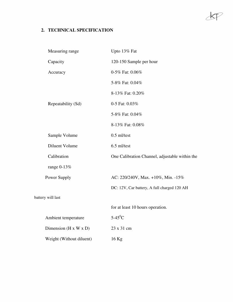
2. TECHNICAL SPECIFICATION
Measuring range Upto 13% Fat
Capacity 120-150 Sample per hour
Accuracy 0-5% Fat: 0.06%
5-8% Fat: 0.04%
8-13% Fat: 0.20%
Repeatability (Sd) 0-5 Fat: 0.03%
5-8% Fat: 0.04%
8-13% Fat: 0.08%
Sample Volume 0.5 ml/test
Diluent Volume 6.5 ml/test
Calibration One Calibration Channel, adjustable within the
range 0-13%
Power Supply AC: 220/240V, Max. +10%, Min. -15%
DC: 12V, Car battery, A full charged 120 AH
battery will last
for at least 10 hours operation.
Ambient temperature 5-450C
Dimension (H x W x D) 23 x 31 cm
Weight (Without diluent) 16 Kg
3. MEASUREMENT PRINCIPLE
3.1 Milko Tester is based on the photometric measurement of light scattered by the
milk sample. The light is scattered by the fat globules, acting as small prisms.
3.2 Not only fat globules in the milk contribute to the light scattering, but also the
proteins may effect the measurement. To eliminate their influence, it is
necessary to dissolve them; EDTA (Ethylene Diamine Tetra Acetic acid)
solution is used for the purpose.
3.3 All the fat globules do not have the same size. The measuring system requires a
constant globule size to provide a fixed relation between the amount if light
scattered to the fat content, the range of globule size is limited in the Milko
Tester to a very narrow region outside the natural range, This is achieved by
homogenizing and bringing the globule size into the range of 0.5 to 1.5
microns.
3.4 Light rays from a photolamp pass through the layer of fluid in the cuvette and
are scattered according to fat globules in the sample. More the fat present in the
cuvette, more is the light scattered and less light passes through the cuvette. The
rays that do pass through the cuvette hits the photocell, producing a current
proportional to the light intensity. The current is fed to a digital readout unit
which gives direct readout of Fat % in milk.
3.5 For better understanding of principal of measurement, photometer and its
associated parts are described below.
3.5.1 Photometer: the Photometer consists of a lamp housing and detector assembly.
The detector assembly includes the cuvette and photocell.
3.5.2 Cuvette: It is made of two hardened glass discs, One has a ground depression of
0.4 mm., the other has two small holder to provide inlet and outlet to the
cuvette.
3.5.3 Photocell: It is silicon detector photocell. Care should be taken not to expose
this photocell to light when not in operation.
3.5.4 Lamp: 12 Volts tungsten Lamp.
4. IDENTIFICATION OF CONTROLS AND CONNECTIONS
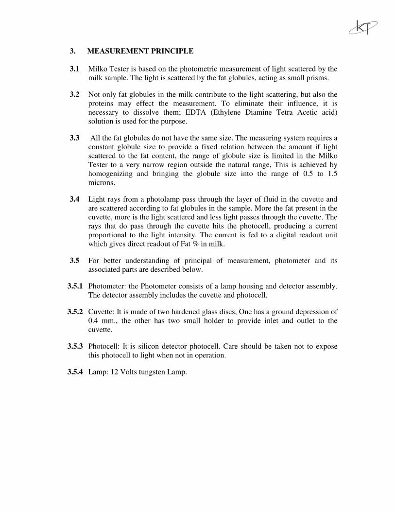
4.1 Front View
1. MILK IN Button
2. MIX OUT Button
3. ZERO setting knob
4. REPEAT button
5. Milk intake tube
6. Mix intake tube
7. Intake valve
8. Screw for bleeding pump
9. Diluent syringe windows
10. Milk syringe windows
11. Pump handle
12. Display
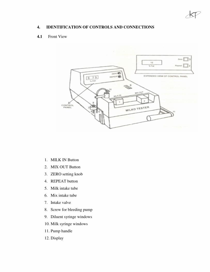
4.2 REAR VIEW
12. Mains ON/OFF switch (does not switch off battery)
13. MAINS socket
14. Inlet stub for diluent
15. Outlet stub for waste
16. Mains fuse (1A for 220/240 V)
17. Battery fuse (10A)
18. Heat Sink
19. 12 V battery socket
20. Switch for selecting type of power supply
LINE – The MT operates on AC MAINS only.
LINE/BATTERY – The MT Operates on AC MAINS/BATTERY and the
battery takes over in the event of AC MAINS failure.
CHARGE - Switches OFF the Power supply from battery to MT
and the battery gets charged if MAINS ON/OFF switch in ON. The MT
cannot be operated if the switch is in this mode.
5. DILUENT PREPARATION
6.1 Diluents are used to dilute the milk sample and dissolve and dissolve the proteins.
6.2 Chemicals required to prepare 10 liters of diluent are as follow:
(i) EDTA Sachet : 52.6 gms., containing;
: 45.0 gms. of EDTA powder and 7.6 gms. of Di – Sodium
hydroxide
(ii) Trifon – X – 100 : 0.5 ml.
(Emulsifier
(iii) Antifoam : 1.0 ml
6.3 Procedure: Take a clean 10 Liters plastic container and add one liter clean
water. Add contents of EDTA sachet, containing diluent powder for 10 liter
solution. Add 0.5 ml. of Triton – X – 100 and 1.0 ml. of Antifoam. Put the lid on
the container and shake it until all the chemicals are dissolved. Then add clean
water until the contents are full 10 liters and shake again to mix the solution.
6.4 The pH of this solution should be between 9.5 to 10.1 Diluent will remain good
for 2 weeks before the Antifoam become inactive. Diluent can be kept longr if
Antifoam is added to the solution from time to time (0.5 ml. for every 2 weeks).
6. INSTALLATION
6.1 Place of installation should be such that there should be sufficient space for diluent
container and Battery also Pump handle of Milko Tester must be easy to reach.
6.2 Check 1 Amp/ fuse in the Mains fuse-holder and 10 Amp. Fuse in the Battery fuse-
holder.
6.3 Connect power cables on mains.
6.4 Use only 12 V Car-battery. Connect RED lead of battery cable to ‘+’ of battery
and BLACK lead to ‘-‘pole. Connect other end of the cable to Milko Tester.

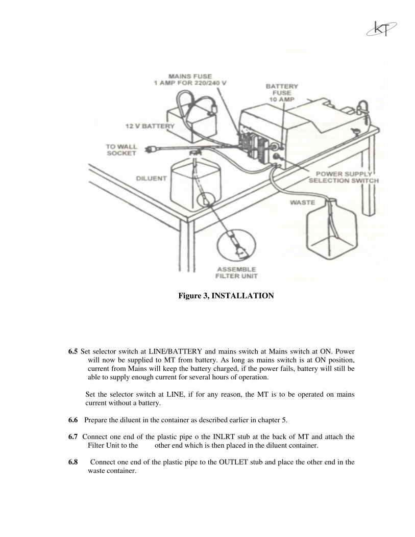
Figure 3, INSTALLATION
6.5 Set selector switch at LINE/BATTERY and mains switch at Mains switch at ON. Power
will now be supplied to MT from battery. As long as mains switch is at ON position,
current from Mains will keep the battery charged, if the power fails, battery will still be
able to supply enough current for several hours of operation.
Set the selector switch at LINE, if for any reason, the MT is to be operated on mains
current without a battery.
6.6 Prepare the diluent in the container as described earlier in chapter 5.
6.7 Connect one end of the plastic pipe o the INLRT stub at the back of MT and attach the
Filter Unit to the other end which is then placed in the diluent container.
6.8 Connect one end of the plastic pipe to the OUTLET stub and place the other end in the
waste container.
6.9 Place empty beaker under milk intake tube and push ‘MILK IN’ and ‘MIX OUT’
buttons alternately until no bubbles are seen in syringes, End by pushing ‘MIX OUT’
button.
7. MILK SAMPLE PREPARATION
7.1 Sampling : The samples measured should be taken from milk in good condition,
i.e. the milk should not have started to curdle or separate, and it should be free of
dirt. Since milk fat is of lower density than the other milk constituents, therefore it
tends to rise to the surface. Gently stir the bulk milk just before sampling to make
sure that sample is a true representative of the bulk. Fresh unpreserved sample
must be tested immediately just before testing, turn the sample upside downs a
few times to mix it properly.
7.2 Preservation : If measurement can not be made immediately after sampling,
then samples can be preserved for maximum 12 hours, without refrigeration, by
adding 1 ml saturated Potassium Dichromate solution in 100 ml. milk. If they are
to be kept longer for measurement and if transportation is necessary, then cool the
preserved sample to 5-10oC but never freeze them. Samples which have been
cooled will be easy to mix if they are warmed upto 30-40oC before being
measured.
8. OPERATION:
8.1 Warm up: If the Milko Tester has been switched-off, then it must be allowed to
warm-up before starting measurement. This is done by just switching on the MT,
half an hour to one hour before measurement.
8.2 De-airing Syringes: The flow system must be free of air bubbles to ensure
proper measurement. Presence of any air bubble in the syringes must be removed
as follows:
Place an empty mix beaker under milk intake tube and push 'MILKIN' & 'MIX
OUT' buttons alternately until no air bubbles are seen in the syringes. End by
pushing 'MIX OUT' button.
8.3 Zero Check: The ZERO setting button is used to set the readout to 0.00when the
cuvette contains pure diluent. Zero check described below should be carried out
daily before starting measurement and then once every half hour for the first 2
hours and then once an hour.
Press REPEAT button to get second decimal on the display. Place the clean empty
mix beaker under the milk intake tube and press 'MILKIN & MIX OUT' buttons
twice alternately to fill the mix beaker with diluent. Move the mix beaker to the
mix intake tube and operate the handle six times up and down. The display would
be around 0.20 in any case this reading should be less then 0.40 Repeat the above
operation two times more to ensure the reading remains same and less than 0.40.
Push the Zero button to set the readout to 0.00 after Zero setting press the
REPEAT button to get one decimal readout.
Note : Once every half hour for the first 2 hours and then once every hour,
momentarily put OFF the MT and put if ON again. (The display should read 0.20-
+ with diluent in the cuvette.)
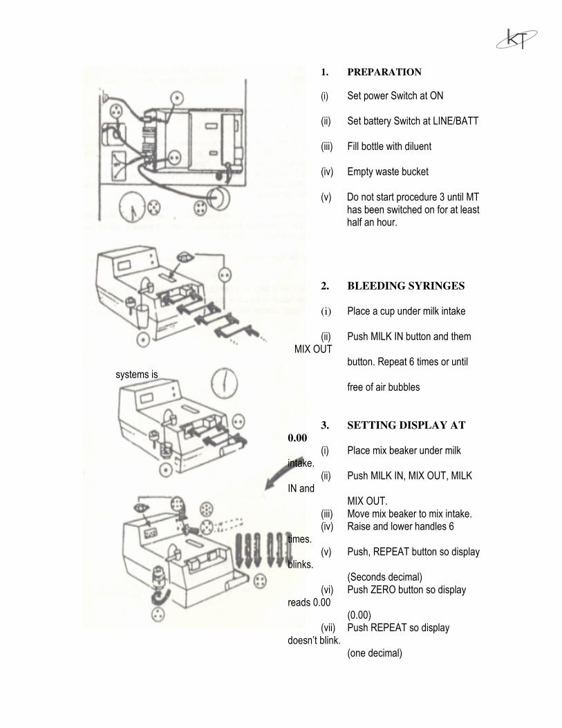
1. PREPARATION
(i) Set power Switch at ON
(ii) Set battery Switch at LINE/BATT
(iii) Fill bottle with diluent
(iv) Empty waste bucket
(v) Do not start procedure 3 until MT has been switched on for at least half an hour.
2. BLEEDING SYRINGES
(i) Place a cup under milk intake
(ii) Push MILK IN button and them MIX OUT
button. Repeat 6 times or until systems is
free of air bubbles
3. SETTING DISPLAY AT
0.00
(i) Place mix beaker under milk intake.
(ii) Push MILK IN, MIX OUT, MILK IN and
MIX OUT. (iii) Move mix beaker to mix intake. (iv) Raise and lower handles 6
times. (v) Push, REPEAT button so display
blinks. (Seconds decimal)
(vi) Push ZERO button so display reads 0.00
(0.00) (vii) Push REPEAT so display
doesn’t blink. (one decimal)
Figure – 4, OPERATION
8.4 Measurement : After de-airing and Zero Setting, measurement can begin. First
result after Zero check/Zero setting should not be recorded as it will be little low.
Therefore, measure the first sample after Xero check twice and record only
second result
Turn the milk sample gently upside down, a few times. Place the sample under
milk intake and fully press 'MILK IN'[ Button.
Slowly remove the sample without touching the milk intake tube. Place clean mix
beaker under milk intake so that if fits into the notch on the side of the MT. Press
'MIX OUT' button in all the way, to dispense milk and diluent into the mix
beaker. Move the mix beaker to the mix intake tube and position. It, so that if rests
in the Notch. Operate the homogenizer handle up & down three times in a steady
movement. When the handle is pressed down the third time, let it rest in bottom
position & result will soon appear on the display. Empty the mix beaker
completely and it is ready for the next sample.
8.5 End of Measurement : Place a clean, empty mix beaker under milk intake tube &
press 'MILK IN & MIX OUT' buttons twice alternately to fill mix beaker with
diluent place the mix beaker under mix intake & operate the handle up and down
six times to flush the cuvette. Switch-of the EMT.
8.6 Deairing the Homogenizer : Air will enter the homogenizer if the handle is
raised when there is no liquid present at the mix intake tube.
Place the mix beaker under milk intake tube & press ' MILK IN & MIX OUT'
buttons twice to fill the beaker with diluent. Raise the handle. Loosen the Bleeder
Screw on the top of mix intake valve. Let the handle drop by its own weight and
tighten the Bleeder Screw again. Operate the handle three more times, up and
down, to be sure that all air is out of the system.
8.7 Electronic check : Refer Section 12.2.8
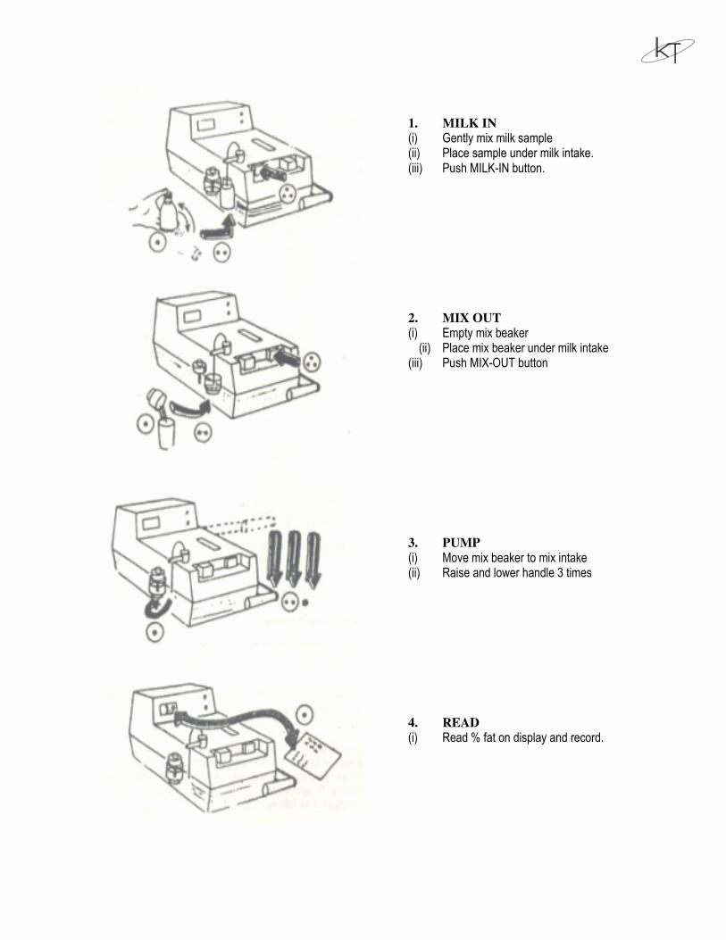
1. MILK IN
(i) Gently mix milk sample (ii) Place sample under milk intake. (iii) Push MILK-IN button. 2. MIX OUT
(i) Empty mix beaker (ii) Place mix beaker under milk intake (iii) Push MIX-OUT button 3. PUMP
(i) Move mix beaker to mix intake (ii) Raise and lower handle 3 times 4. READ
(i) Read % fat on display and record.
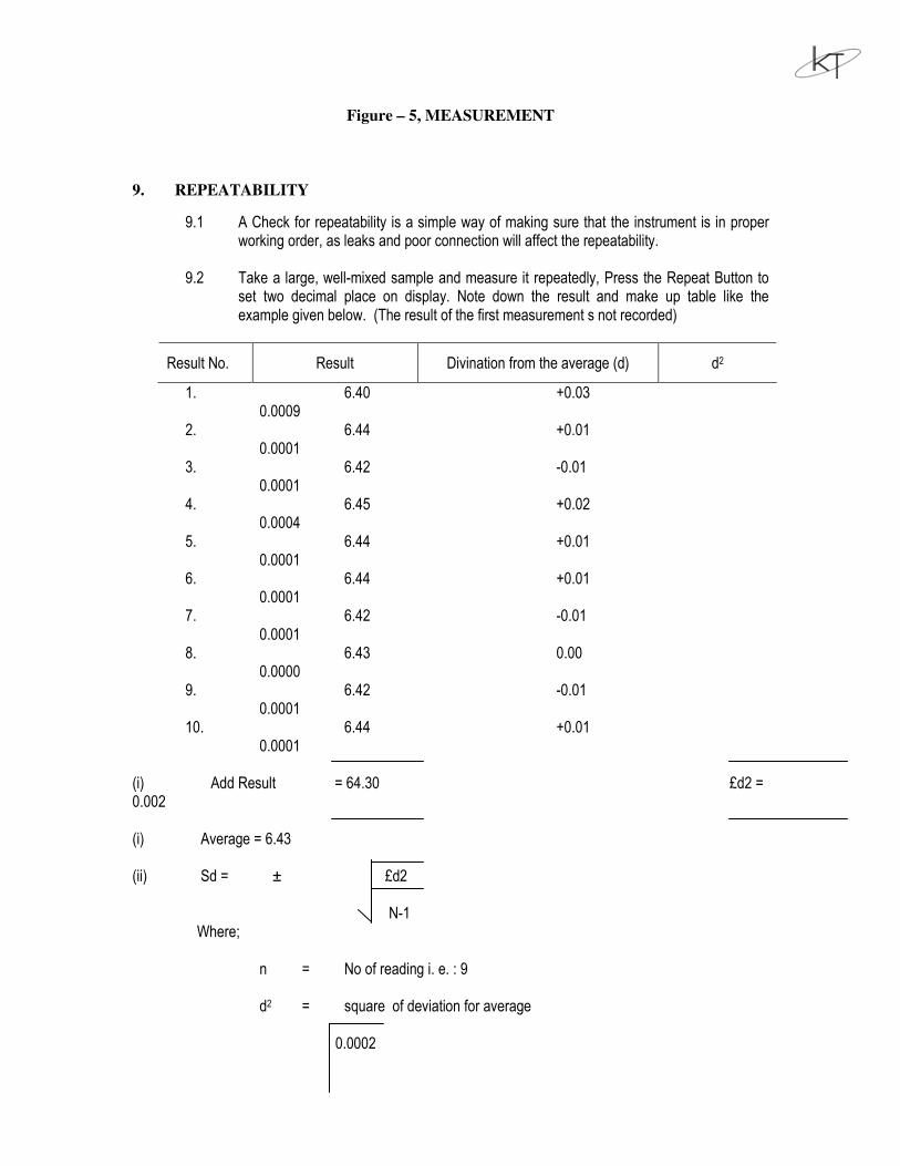
Figure – 5, MEASUREMENT
9. REPEATABILITY
9.1 A Check for repeatability is a simple way of making sure that the instrument is in proper working order, as leaks and poor connection will affect the repeatability.
9.2 Take a large, well-mixed sample and measure it repeatedly, Press the Repeat Button to
set two decimal place on display. Note down the result and make up table like the example given below. (The result of the first measurement s not recorded)
Result No. Result Divination from the average (d) d2
1. 6.40 +0.03 0.0009
2. 6.44 +0.01 0.0001
3. 6.42 -0.01 0.0001
4. 6.45 +0.02 0.0004
5. 6.44 +0.01 0.0001
6. 6.44 +0.01 0.0001
7. 6.42 -0.01 0.0001
8. 6.43 0.00 0.0000
9. 6.42 -0.01 0.0001
10. 6.44 +0.01 0.0001
(i) Add Result = 64.30 £d2 = 0.002 (i) Average = 6.43 (ii) Sd = ± £d2 N-1 Where; n = No of reading i. e. : 9 d2 = square of deviation for average 0.0002
9 == 0.014 (iii) Compare the Sd with the specified limits preserved earlier 10. CALIBRATION
10.1 The purpose of calibration is to adjust the instrument of give result over the whole measuring range. There are 2 step in calibration, one to give a correct linearity and the over to give correct results when compared with the results of a reference method.
10.2 if the milk sample of different fat content are measured, one expects the instrument to show these results within some small limit. If all result are too high or too low by the same proportion, the linearity is all right. Then test the known high fat reference sample on MT and turn ADJUST SCREW (P3 on are too high or vice versa, then the linearity must be adjusted as follows;
Take one sample of high fat content (Actual fat is of no importance,)
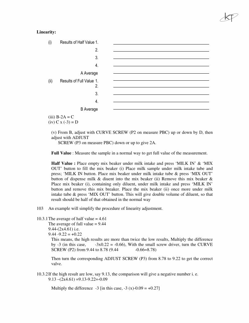
Linearity:
(i) Results of Half Value 1.
2.
3.
4.
A Average
(ii) Results of Full Value 1. 2.
3.
4.
B Average
(iii) B-2A = C
(iv) C x (-3) = D
(v) From B, adjust with CURVE SCREW (P2 on measure PBC) up or down by D, then
adjust with ADJUST
SCREW (P3 on measure PBC) down or up to give 2A.
Full Value : Measure the sample in a normal way to get full value of the measurement.
Half Value : Place empty mix beaker under milk intake and press ‘MILK IN’ & ‘MIX
OUT’ button to fill the mix beaker (i) Place milk sample under milk intake tube and
press; ‘MILK IN button. Place mix beaker under milk intake tube & press ‘MIX OUT’
button of dispense milk & diuent into the mix beaker (ii) Remove this mix beaker &
Place mix beaker (i), containing only diluent, under milk intake and press ‘MILK IN’
button and remove this mix breaker. Place the mix beaker (ii) once more under milk
intake tube & press ‘MIX OUT’ button. This will give double volume of diluent, so that
result should be half of that obtained in the normal way
103 An example will simplify the procedure of linearity adjustment.
10.3.1 The average of half value = 4.61
The average of full value = 9.44
9.44-(2x4.61) i.e.
9.44 -9.22 = +0.22
This means, the high results are more than twice the low results, Multiply the difference
by -3 (in this case, -3x0.22 = -0.66), With the small screw driver, turn the CURVE
SCREW (P2) from 9.44 to 8.78 (9.44 -0.66=8.78)
Then turn the corresponding ADJUST SCREW (P3) from 8.78 to 9.22 to get the correct
valve.
10.3.2 If the high result are low, say 9.13, the comparison will give a negative number i. e.
9.13 –(2x4.61) =9.13-9.22=-0.09
Multiply the difference -3 [in this case, -3 (x)-0.09 = +0.27]
Which means that CURVE SCREW (P2) Must be adjusted upwards instead of down
wards and ADJUST (P3) Must be adjusted downwards to the correct value.
10.3.3 Continue the above procedure untill the difference ‘C’ is less than 0.04
11. USEFUL HINTS ON OPERATION
11.1 The instrument should be kept clean.
11.2 Half an hour to one hour warm up, de-airing syringes & check must not be
forgotten before starting the measurement.
11.3 When pressing the 'MILK IN' & 'MIX OUT' buttons, use the ridge on the cabinet
to support the fingers, and press the buttons, evenly with the thumb. This will
improve your instrument's performance.
11.4 Chemicals must be stored in a clean & dry place.
11.5 It is not necessary to clean the milk intake tube and mix intake tube between each
sample measurement. If the milk intake tube reaches far into the sample, it may be
necessary to wipe it between sampling & dispensing to avoid carry over. This
happens if milk from one sample is left on the outside of the milk intake tube and
is then mixed with the next sample.
11.6 Place milk sample under the milk intake tube so that the tip of the tube is
approximately 5 mm below the surface. Though 5 mm is not so critical but the
tube should be dipped at the same distance below the surface in every sample.
11.7 During storms with lightening. unplug the MT from mains supply to avoid danger
of damages to the instrument.
11.8 MT should preferably be connected with battery & normal position of operation
is; Mains at ON and selector switch at LINE/BATTERY. If mains fails, battery
will still be able to supply enough current for several hours of operation. If battery
reserve is low, then set selector switch at CHARGE, with Mains at ON. This
switches off power supply to measuring circuit, A completely drained battery will
be fully charged in 8.12 hours.
11.9 Battery fuse will blow if leads are connected to wrong poles on the battery.
Always remember to connect red lead of battery cable to "+ve" pole of 12V car
battery and black lead to "1Ve" pole.
11.10 Check the acid level of the battery once a fortnight and refill it if necessary with
distilled water until plates are just covered.
12. USEFUL HINTS ON PREVENTIVE MAINTENANCE
12.1 Milko Tester accurate results if;
(i) It shows a stable 'Zero at 0.20(+0.03) upto an hour during the time milk is
being tested (See sec. 8.3, OPERATION)
(ii) It shows a stable read out (+0.03 after the third stroke when operated on
second decimal.
(iii) It shows essentially the same readout when the same sample is tested
again & again.
(iv) It has been calibrated by comparing its results with "GERBER" method.
However, it may give misleading results if one or more of the above
features fail. Therefore make a quick check every day at start up, and a
compete check once a week.
12.2 The hints below will help you locate and remedy troubles, should they appear.
12.2.1 Display fails :
If no display, the supply voltage from Battery or Mains probably has failed.
Either of the fuses has burnt out. Use 10A fuse for battery and 1A fuse for mains.
10A fuse is intended to burn out if the battery's negative pole is connected to the
MT positive terminal & vice versa.
12.2.2 Zero-setting fails :
(i) First apply double measure of diluent to the mix intake and operate the
handle six times.
(ii) If only any one digit of the 4 digit display is glowing (Showing any
number) which remains unaffected by 'ZERO' button but check 12.2.8 (i)
is OK, the lamp is probably burnt out or the photocell is faulty. However,
first check the supply voltage. Battery should be min. 10.5V, Mains
minimum 190V. Check loose or broken connection to lamp or photocell.
(iii) If above procedure fails to locate error or in case the reading show zero
and can not be raised. then either photocell or lamp or Power
PCB/Measure PCB is faulty.
12.2.3 Zero drifts :
(i) The 'zero' drift means that 0.20 readout is not stable. Zero drift is normal
during warm-up period because Thermo block temperature needs time to
stabilize.
(ii) If 'zero' continues to drift or fluctuate or 0.2_+0.03 can not be obtained
after warm-up/Power ON, then check supply voltage.
(iii) Zero drift may b caused by air intake. Therefore make sure that
homogenizer pump is perfectly deaired and that the mix-in take tube is
firmly fixed in the lowest possible position in the slot, otherwise the
volume supplied by the syringes will not be sufficient to give an air free
charge at the third pump stroke.
(iv) Even if air intake is excluded, air bubble may appear in the cuvette (causing
the readout to drifts slowly upscale after pump operation & goes back very
slowly) if the valve V3 after cuvette outlet is leaking. A quick check for
this is to raise the external waste tube to a position above the MT to
increase cuvette pressure. If this stabilizes the readout, then clean Valve V
3.
(v) If zero drifts quickly up-scale by about 03.-1% after pump operation & goes
back slowly, then this may be due to the moisture or condensation on the
outside of the cuvette glass, which must be carefully wiped dry.
(vi) In rare cases, malfunctions of the photocell or lamp may cause Zero drift.
12.2.4 Readout drifts after a milk test:
A slow down-scale by 0.01-0.04% considered normal & does not affect results on
one decimal readout. If drift is more, then that is because of possible presence of
moisture or leakage in the cuvette. There for cuvette may need new gaskets. It s a
important that the inside of the photometer must be carefully wiped dry before
assembly. This drift may also be caused by dirt in value V3, therefore lean the
value V3 also.
12.2.5 Repeatability fails :
When the same sample is tested again and again it must show repeatability within
the prescribed tolerance limit. If higher variation appear, check the following.
12.2.6 Is the MT being operated correctly?
(i) 'MILK IN' & MIX OUT' button should be pressed smoothly and
uniformly.
(ii) Dont' push 'MIX OUT' button so fast that mix splashed out of the mix
beaker during the discharge.
(iii) Never touch the milk intake tube when removing the sample bottle.
12.2.7 Is the test sample in good condition?
If it is acidified, churned out, separated or otherwise non-uniform, the good
repeatability can not be obtained.
12.2.8 Instrument checks :
(i) Remove the connections from the photocell coming to the spades at the
top of Measure PCB, only any one of the digits of the 4-digit display
should glow (showing any number 0-9). Now short the spades with a piece
of wire or tweezers/forceps, the display should read 00.00, then measure
PCB is OK, otherwise it is faulty.
(ii) Operate the MT with the diluent along (no milk), note that there is no zero
drift.
(iii) If zero is stable, the lamp cuvette & photocell are in good order and the
trouble must be in the syringe assembly. The possible cause is leaking of
valves V1, V2, V3 which will cause high & fluctuating results.
12.2.9 Miscellaneous problems :
(i) If it is difficult to suck mix from mix intake tube, then clean the ball of mix
intake valve.
(ii) If diluent leaks from milk intake tube, then clean valve V2.
(iii) If fluid leaks from bleeder screw of mix intake valve, then replace gasket
of bleeder screw. ]
(iv) If flued leaks from mix intake valve when handle is pressed down, then
replace the ball of intake valve.
13 PARE PARTS INDENTIFICATION
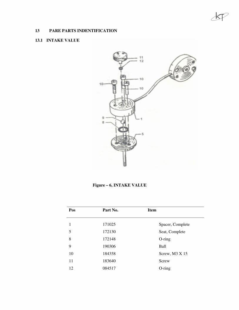
13.1 INTAKE VALUE
Figure – 6, INTAKE VALUE
Pos Part No. Item
1 171025 Spacer, Complete
5 172130 Seat, Complete
8 172148 O-ring
9 190306 Ball
10 184358 Screw, M3 X 15
11 183640 Screw
12 084517 O-ring
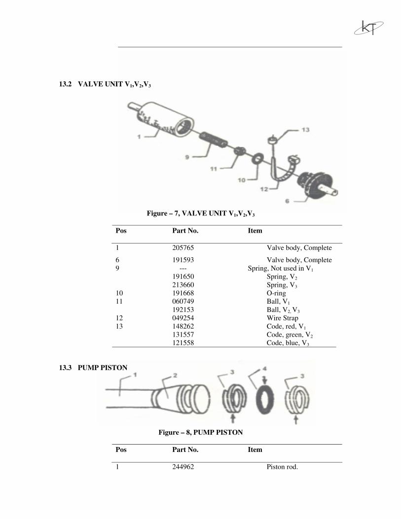
13.2 VALVE UNIT V1,V2,V3
Figure – 7, VALVE UNIT V1,V2,V3
Pos Part No. Item
1 205765 Valve body, Complete
6 191593 Valve body, Complete
9 --- Spring, Not used in V1
191650 Spring, V2
213660 Spring, V3
10 191668 O-ring
11 060749 Ball, V1
192153 Ball, V2, V3
12 049254 Wire Strap
13 148262 Code, red, V1
131557 Code, green, V2
121558 Code, blue, V3
13.3 PUMP PISTON
Figure – 8, PUMP PISTON
Pos Part No. Item
1 244962 Piston rod.

2. 272088 Piston steel
3. 171108 Support, ring
4. 243857 O-ring
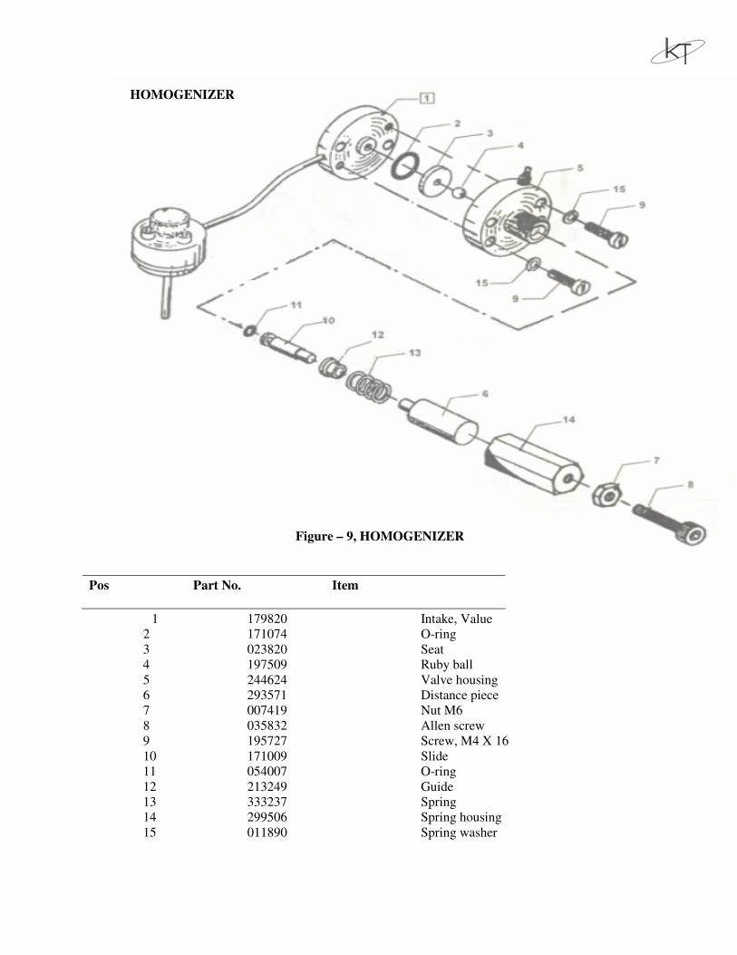
HOMOGENIZER
Figure – 9, HOMOGENIZER
1 179820 Intake, Value
2 171074 O-ring
3 023820 Seat
4 197509 Ruby ball
5 244624 Valve housing
6 293571 Distance piece
7 007419 Nut M6
8 035832 Allen screw
9 195727 Screw, M4 X 16
10 171009 Slide
11 054007 O-ring
12 213249 Guide
13 333237 Spring
14 299506 Spring housing
15 011890 Spring washer
Pos Part No. Item
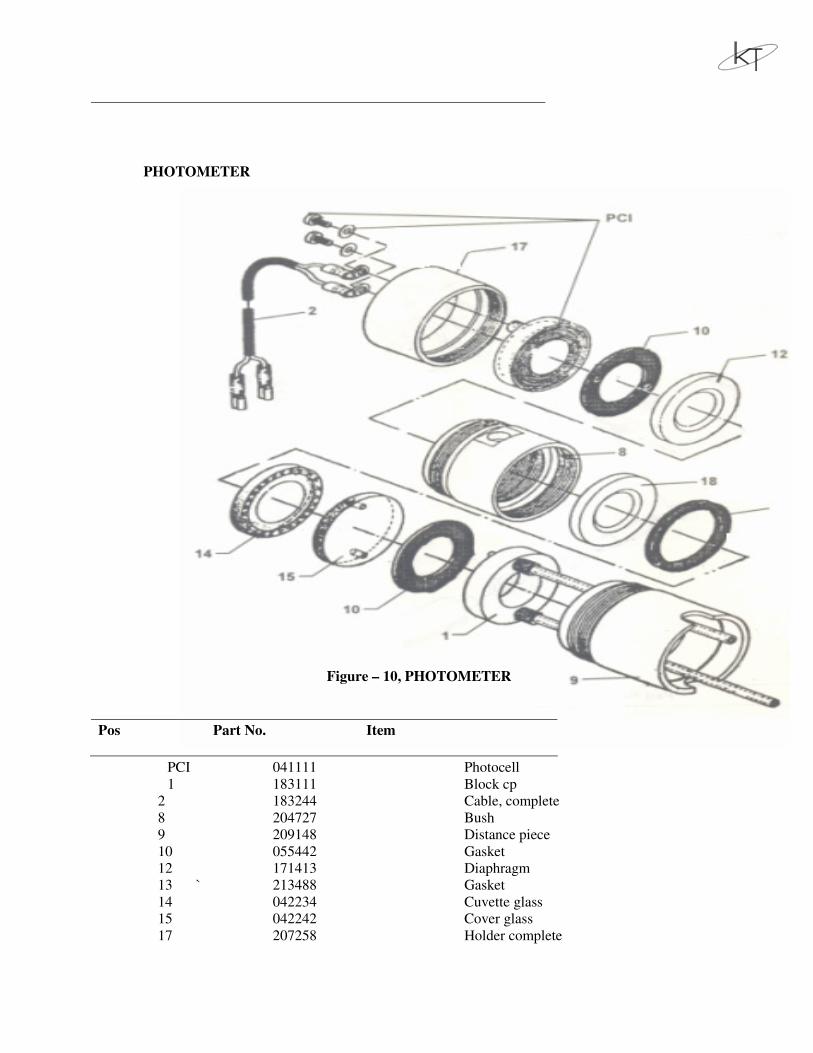
PHOTOMETER
Figure – 10, PHOTOMETER
PCI 041111 Photocell
1 183111 Block cp
2 183244 Cable, complete
8 204727 Bush
9 209148 Distance piece
10 055442 Gasket
12 171413 Diaphragm
13 ` 213488 Gasket
14 042234 Cuvette glass
15 042242 Cover glass
17 207258 Holder complete
Pos Part No. Item

18 207233 Diaphragm