Embed Size (px)
Citation preview
Proceedings of the International Symposium on Bond Behaviour of FRP in Structures (BBFS 2005) Chen and Teng (eds)
© 2005 International Institute for FRP in Construction
425
BONDING STRENGTH AND FRACTURE MECHANISMS IN COMPOSITE STEEL-CFRP ELEMENTS
Al-Emrani M 1, Linghoff D.2 and Kliger R 3 1 Assistant Prof., Department of Structural Engineering, Chalmers University of Technology, Sweden.
Sven Hultins gata 8, 412 96 Göteborg, Sweden. Email: [email protected]. 2 Graduate Student, Department of Structural Engineering, Chalmers University of Technology, Sweden.
3 Professor, Department of Structural Engineering, Chalmers University of Technology, Sweden. ABSTRACT The use of advanced composite materials in strengthening and repair of existing structures is increasing rapidly. One specific area in which the technique has been introduced lately is the strengthening of metallic structures with bonded carbon-fibre laminates. In this paper, the behaviour of composite steel-CFRP members is studied experimentally and using FE-analysis. A new type of test specimen has been developed for this purpose. By examining different combinations of CFRP-laminates and adhesives, different types of fracture mode could be examined. The tested composite elements also displayed different behaviour and a large difference in strength and ductility could be observed. KEYWORDS Bonding, strengthening, steel, CFRP, adhesive, interfacial, shear stresses.
INTRODUCTION The use of composite materials for the strengthening and repair of existing structures has increased significantly during the last decade. The high durability and fatigue resistance of these materials and their superior strength-to-weight ratio make them compete easily with other traditional building materials in this field. From being mainly devoted to concrete structures, the use of composite materials in strengthening and repair work has extended to include timber, masonry and lately even metallic structures. Several field applications have been reported where steel and wrought iron structures (mostly bridges) have been strengthened or repaired using adhesively-bonded carbon fibre laminates (CFRL)(Luke 2001; Miller et al. 2001). In some cases, prestressing of the laminates was employed to obtain more efficient strengthening scheme and higher utilization of the high tensile strength of the composite material (Bassetti 2001). Several experimental studies have also been conducted in this area. Results from laboratory tests on steel (Bassetti 2001; Mertz et al. 1996) and composite steel-concrete beams (Al-Saidy et al. 2004; Sen et al. 2001; Tavakkolizadeh and Saadatmanesh 2003) strengthened with adhesively bonded CFRL have been reported. The vas majority of the tests were devoted to beams in bending and they cover a wide range of application areas including upgrading of the bending capacity, increasing bending stiffness, repairing fatigue cracked elements and increasing the fatigue strength of steel beams. In general, the major focus in the reported experimental studies has been pointed towards the degree of strengthening that can be obtained by using this technique. In almost all cases, large-scale beams were used for this purpose. More detailed studies focusing on the behaviour and strength of composite steel-CFRL elements are rather scarce. Furthermore, analytical work conducted in this field animates mainly from the work performed on concrete beams and is limited to linear elastic analysis only. Consequently, there is still today some lack of knowledge regarding the behaviour and strength of composite steel-CFRL elements. In particular, the behaviour, strength and possible fracture modes of these composite members in the post-yielding stage need to be studied more closely. There is also some lack of knowledge regarding how proper selection of materials (carbon fibre, adhesives) for the different applications (increased strength in the ULS, increased stiffness, fatigue, ..) should be made. For example, the general opinion that high modulus laminates are more effective in steel applications does not always hold true. Research concerning the strengthening and repair of metallic structures using bonded CFRL has been ongoing at Chalmers University of Technology in Sweden since 2003. Various types of laboratory test and analytical and numerical work have been performed in this field. In this paper, the results from an experimental study on the behaviour and strength of composite steel-CFRL elements are presented. The main objectives of these tests were:
426
1. to study the behaviour of composite steel-CFRL elements, in particular in the post-yielding stage, 2. to examine possible fracture modes that can be obtained for steel elements strengthened by bonded
CFRL, 3. to evaluate the effect of various material properties on the strength and ductility of the composite
elements as well as on the type of fracture mode obtained for these elements.
Lacking standardised tests that can be used for these purposes, a new type of tests specimen was developed for the tests. The shape and dimensions of the new test specimen were established based on the results obtained from extensive finite-element analysis.
MATERIAL TESTS There is today a wide range of different carbon-fibre-reinforced composites in the market with a variety of strength and stiffness classes. Typically, laminates with ultimate tensile strength of 1300 to 3500 MPa are available with axial stiffness ranging from 450 to 150 GPa. Two adhesive-laminate systems, provided by two different manufacturers, were used in the experimental study reported in this paper. These systems are designated A and B. Relevant material properties for the laminates and adhesives had to be established first. Tension tests were performed on dog-bone adhesive specimens at four different curing times and four different temperatures. Similar tension tests were also carried out on the CFR-laminates. Material properties in the two main directions (i.e. parallel and perpendicular to the direction of the fibres) were obtained. Table 1 shows the relevant material properties for the two types of adhesive used in the tests, while the strength and stiffness of the laminates are shown in Table 2. For the laminates, the measured values differed somewhat from the values provided by the manufacturer. This difference was markedly large concerning the axial stiffness of the two high-modulus laminates B17 and B40.
Table 1 Material properties for the two types of adhesive used in the tests. Average values at room temperature after 7 curing days
Adhesive E [GPa] σult [MPa] εult [x103] υ A 14 32 3 0.27 B 6.5 24 7 0.35
Table 2 Measured strength and stiffness (parallel to the fibres)
of the four types of laminate used in the tests. CFRL type Thickness E// σ//,ult
A12 1.2 155 1932 B12 1.43 174 1855 B17 1.95 383 1252 B40 4.4 362 (1252)*
* No reliable value for the ultimate tensile strength for this type of laminate could be obtained. Being of the same material as B17, the same tensile strength is adopted to both laminates.
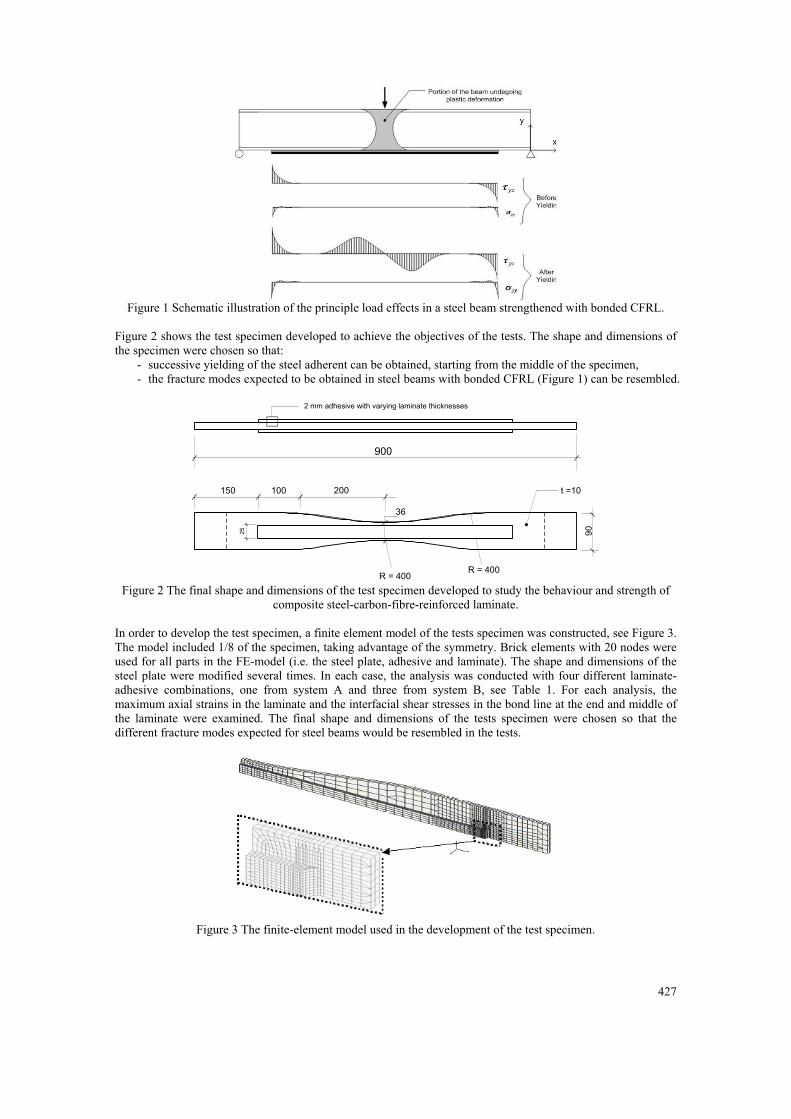
DEVELOPMENT OF TEST SPECIMEN AND FINITE-ELEMENT MODELLING Figure 1 shows schematically the load effects along the bond line in a steel beam strengthened with adhesively bonded CFRL and loaded in bending. Four possible failure modes can be recognised:
1. rapture of the laminate when the maximum axial stress in the laminate reaches its ultimate strength, 2. debonding failure due to maximum shear in bond line at the end of the laminate, 3. debonding failure due to maximum shear in bond line in the middle of the laminate. 4. interlaminar shear failure (delamination) at the end of the laminate.
The governing failure mode in a specific beam will primarily depend on: the properties of the materials used (such as laminate and adhesive stiffness and strength), geometrical properties (such as laminate and adhesive thickness and width and laminate end preparation), and on mechanical properties (like the characteristics of the bonding surfaces and possible defects in the bonding line).
427
Figure 1 Schematic illustration of the principle load effects in a steel beam strengthened with bonded CFRL.
Figure 2 shows the test specimen developed to achieve the objectives of the tests. The shape and dimensions of the specimen were chosen so that:
- successive yielding of the steel adherent can be obtained, starting from the middle of the specimen, - the fracture modes expected to be obtained in steel beams with bonded CFRL (Figure 1) can be resembled.
900
R = 400R = 400
90
200100150 t =10
25
2 mm adhesive with varying laminate thicknesses
36
Figure 2 The final shape and dimensions of the test specimen developed to study the behaviour and strength of
composite steel-carbon-fibre-reinforced laminate. In order to develop the test specimen, a finite element model of the tests specimen was constructed, see Figure 3. The model included 1/8 of the specimen, taking advantage of the symmetry. Brick elements with 20 nodes were used for all parts in the FE-model (i.e. the steel plate, adhesive and laminate). The shape and dimensions of the steel plate were modified several times. In each case, the analysis was conducted with four different laminate-adhesive combinations, one from system A and three from system B, see Table 1. For each analysis, the maximum axial strains in the laminate and the interfacial shear stresses in the bond line at the end and middle of the laminate were examined. The final shape and dimensions of the tests specimen were chosen so that the different fracture modes expected for steel beams would be resembled in the tests.
Figure 3 The finite-element model used in the development of the test specimen.
428
PRODUCTION AND PREPARATION OF TEST SPECIMENS AND TESTING PROCEDURE Four composite steel-CFRL elements and one reference element (with steel only) were manufactured and tested. One of the composite elements was made with of system A (i.e. adhesive A and laminate A12) while system B was used in the remaining three elements. In order to avoid any residual stress effects that might result from flame cutting and mechanical preparation of the steel plate, the latter was cut to the final shape using water jet. The laminates where also cut to the desired length and width using the same technique. Prior to bonding, the opposite surfaces of the steel plate where the laminates are to be bonded were sandblasted. Immediately, the steel surfaces were cleaned with alcohol and coated with a thin layer of primer to prevent oxidation and improve bonding. Upon curing of the primer, the laminates and the bonding areas of the steel plate were covered with adhesive and a roller was used to press the laminate on the steel surface. Small spacers made of timber were used to assure a uniform adhesive layer thickness of 2mm. The specimens were the left to cure for seven days. Each test specimen was equipped with a number of strain gauges (2mm long) to monitor the axial strains at different locations in the laminate and the steel plate. A universal uniaxial testing machine was used to load each test specimen in tension at a displacement rate of 0,25 mm/min.
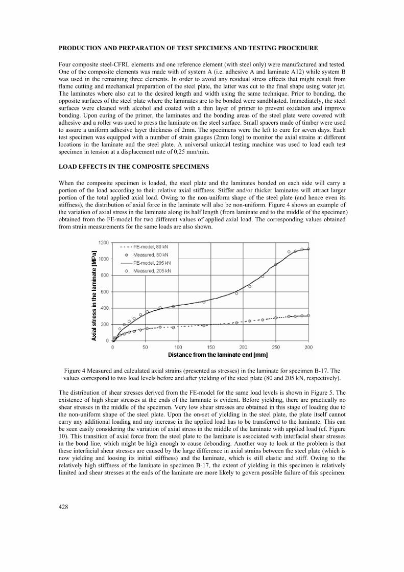
LOAD EFFECTS IN THE COMPOSITE SPECIMENS When the composite specimen is loaded, the steel plate and the laminates bonded on each side will carry a portion of the load according to their relative axial stiffness. Stiffer and/or thicker laminates will attract larger portion of the total applied axial load. Owing to the non-uniform shape of the steel plate (and hence even its stiffness), the distribution of axial force in the laminate will also be non-uniform. Figure 4 shows an example of the variation of axial stress in the laminate along its half length (from laminate end to the middle of the specimen) obtained from the FE-model for two different values of applied axial load. The corresponding values obtained from strain measurements for the same loads are also shown.
Figure 4 Measured and calculated axial strains (presented as stresses) in the laminate for specimen B-17. The values correspond to two load levels before and after yielding of the steel plate (80 and 205 kN, respectively).
The distribution of shear stresses derived from the FE-model for the same load levels is shown in Figure 5. The existence of high shear stresses at the ends of the laminate is evident. Before yielding, there are practically no shear stresses in the middle of the specimen. Very low shear stresses are obtained in this stage of loading due to the non-uniform shape of the steel plate. Upon the on-set of yielding in the steel plate, the plate itself cannot carry any additional loading and any increase in the applied load has to be transferred to the laminate. This can be seen easily considering the variation of axial stress in the middle of the laminate with applied load (cf. Figure 10). This transition of axial force from the steel plate to the laminate is associated with interfacial shear stresses in the bond line, which might be high enough to cause debonding. Another way to look at the problem is that these interfacial shear stresses are caused by the large difference in axial strains between the steel plate (which is now yielding and loosing its initial stiffness) and the laminate, which is still elastic and stiff. Owing to the relatively high stiffness of the laminate in specimen B-17, the extent of yielding in this specimen is relatively limited and shear stresses at the ends of the laminate are more likely to govern possible failure of this specimen.
429
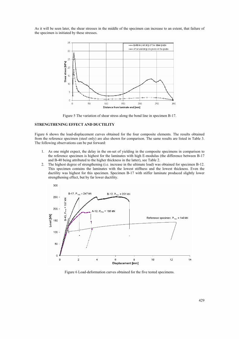
As it will be seen later, the shear stresses in the middle of the specimen can increase to an extent, that failure of the specimen is initiated by these stresses.
Figure 5 The variation of shear stress along the bond line in specimen B-17.
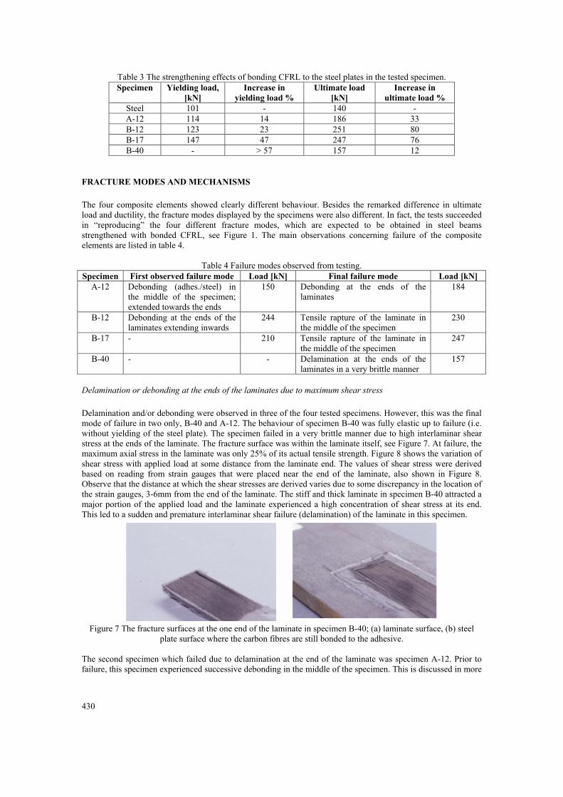
STRENGTHENING EFFECT AND DUCTILITY Figure 6 shows the load-displacement curves obtained for the four composite elements. The results obtained from the reference specimen (steel only) are also shown for comparison. The same results are listed in Table 3. The following observations can be put forward:
1. As one might expect, the delay in the on-set of yielding in the composite specimens in comparison to the reference specimen is highest for the laminates with high E-modulus (the difference between B-17 and B-40 being attributed to the higher thickness in the latter), see Table 2.
2. The highest degree of strengthening (i.e. increase in the ultimate load) was obtained for specimen B-12. This specimen contains the laminates with the lowest stiffness and the lowest thickness. Even the ductility was highest for this specimen. Specimen B-17 with stiffer laminate produced slightly lower strengthening effect, but by far lower ductility.
Figure 6 Load-deformation curves obtained for the five tested specimens.
430
Table 3 The strengthening effects of bonding CFRL to the steel plates in the tested specimen. Specimen Yielding load,
[kN] Increase in
yielding load % Ultimate load
[kN] Increase in
ultimate load % Steel 101 - 140 - A-12 114 14 186 33 B-12 123 23 251 80 B-17 147 47 247 76 B-40 - > 57 157 12
FRACTURE MODES AND MECHANISMS The four composite elements showed clearly different behaviour. Besides the remarked difference in ultimate load and ductility, the fracture modes displayed by the specimens were also different. In fact, the tests succeeded in “reproducing” the four different fracture modes, which are expected to be obtained in steel beams strengthened with bonded CFRL, see Figure 1. The main observations concerning failure of the composite elements are listed in table 4.
Table 4 Failure modes observed from testing. Specimen First observed failure mode Load [kN] Final failure mode Load [kN]
A-12 Debonding (adhes./steel) in the middle of the specimen; extended towards the ends
150 Debonding at the ends of the laminates
184
B-12 Debonding at the ends of the laminates extending inwards
244 Tensile rapture of the laminate in the middle of the specimen
230
B-17 - 210 Tensile rapture of the laminate in the middle of the specimen
247
B-40 - - Delamination at the ends of the laminates in a very brittle manner
157
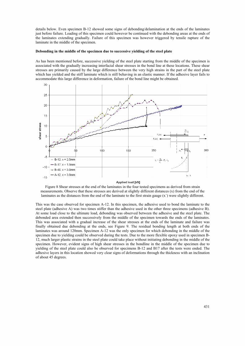
Delamination or debonding at the ends of the laminates due to maximum shear stress Delamination and/or debonding were observed in three of the four tested specimens. However, this was the final mode of failure in two only, B-40 and A-12. The behaviour of specimen B-40 was fully elastic up to failure (i.e. without yielding of the steel plate). The specimen failed in a very brittle manner due to high interlaminar shear stress at the ends of the laminate. The fracture surface was within the laminate itself, see Figure 7. At failure, the maximum axial stress in the laminate was only 25% of its actual tensile strength. Figure 8 shows the variation of shear stress with applied load at some distance from the laminate end. The values of shear stress were derived based on reading from strain gauges that were placed near the end of the laminate, also shown in Figure 8. Observe that the distance at which the shear stresses are derived varies due to some discrepancy in the location of the strain gauges, 3-6mm from the end of the laminate. The stiff and thick laminate in specimen B-40 attracted a major portion of the applied load and the laminate experienced a high concentration of shear stress at its end. This led to a sudden and premature interlaminar shear failure (delamination) of the laminate in this specimen.
Figure 7 The fracture surfaces at the one end of the laminate in specimen B-40; (a) laminate surface, (b) steel
plate surface where the carbon fibres are still bonded to the adhesive. The second specimen which failed due to delamination at the end of the laminate was specimen A-12. Prior to failure, this specimen experienced successive debonding in the middle of the specimen. This is discussed in more
431
details below. Even specimen B-12 showed some signs of debonding/delamination at the ends of the laminates just before failure. Loading of this specimen could however be continued with the debonding areas at the ends of the laminates extending gradually. Failure of this specimen was however triggered by tensile rapture of the laminate in the middle of the specimen.
Debonding in the middle of the specimen due to successive yielding of the steel plate As has been mentioned before, successive yielding of the steel plate starting from the middle of the specimen is associated with the gradually increasing interfacial shear stresses in the bond line at these locations. These shear stresses are primarily caused by the large difference between the very high strains in the part of the steel plate which has yielded and the stiff laminate which is still behaving in an elastic manner. If the adhesive layer fails to accommodate this large difference in deformation, failure of the bond line might be obtained.
Figure 8 Shear stresses at the end of the laminates in the four tested specimens as derived from strain
measurements. Observe that these stresses are derived at slightly different distances (x) from the end of the laminates as the distances from the end of the laminate to the first strain gauge (x´) were slightly different.
This was the case observed for specimen A-12. In this specimen, the adhesive used to bond the laminate to the steel plate (adhesive A) was two times stiffer than the adhesive used in the other three specimens (adhesive B). At some load close to the ultimate load, debonding was observed between the adhesive and the steel plate. The debonded area extended then successively from the middle of the specimen towards the ends of the laminates. This was associated with a gradual increase of the shear stresses at the ends of the laminate and failure was finally obtained due debonding at the ends, see Figure 9. The residual bonding length at both ends of the laminates was around 120mm. Specimen A-12 was the only specimen for which debonding in the middle of the specimen due to yielding could be observed during the tests. Due to the more flexible epoxy used in specimen B-12, much larger plastic strains in the steel plate could take place without initiating debonding in the middle of the specimen. However, evident signs of high shear stresses in the bondline in the middle of the specimen due to yielding of the steel plate could also be observed for specimens B-12 and B17 after the tests were ended. The adhesive layers in this location showed very clear signs of deformations through the thickness with an inclination of about 45 degrees.
432
Figure 9 The failure surface in specimen A-12.
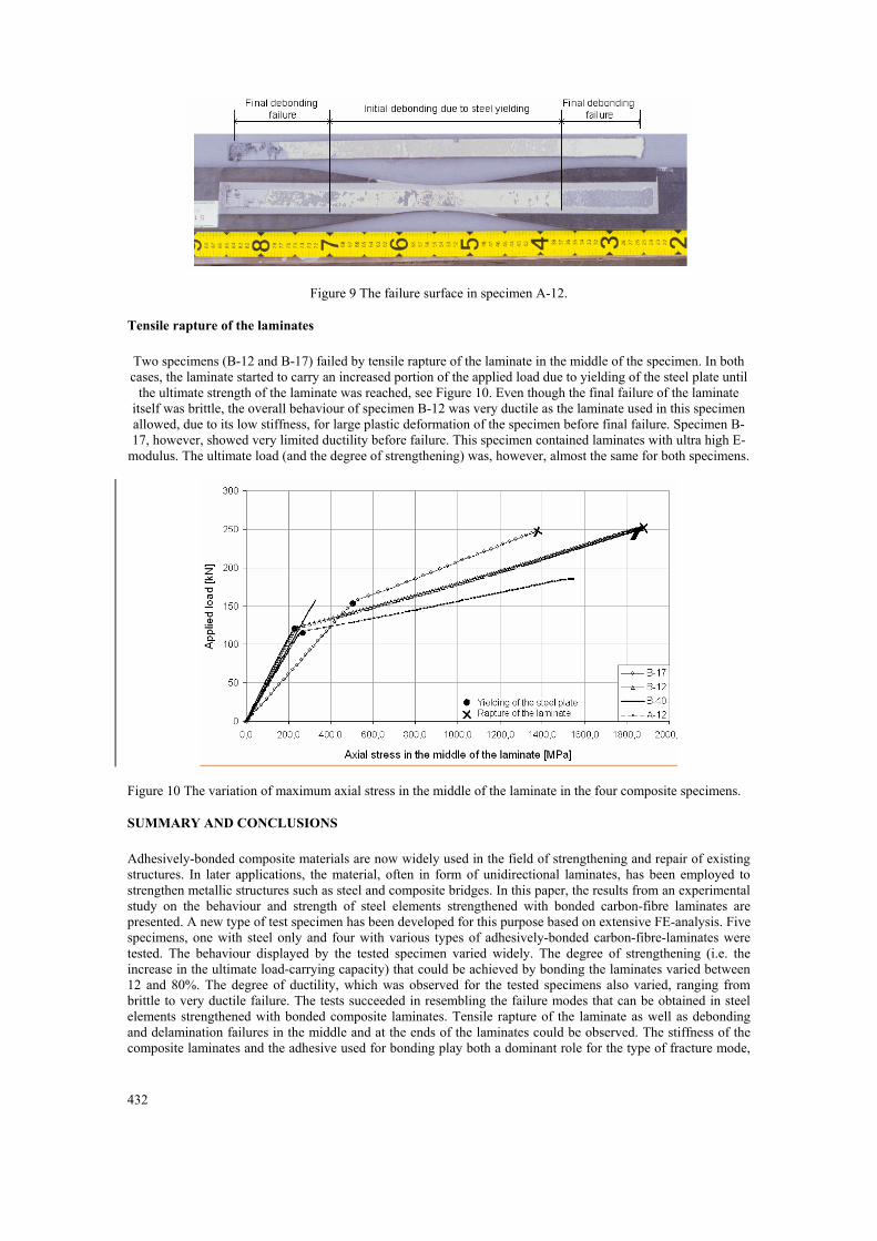
Tensile rapture of the laminates Two specimens (B-12 and B-17) failed by tensile rapture of the laminate in the middle of the specimen. In both cases, the laminate started to carry an increased portion of the applied load due to yielding of the steel plate until
the ultimate strength of the laminate was reached, see Figure 10. Even though the final failure of the laminate itself was brittle, the overall behaviour of specimen B-12 was very ductile as the laminate used in this specimen allowed, due to its low stiffness, for large plastic deformation of the specimen before final failure. Specimen B-17, however, showed very limited ductility before failure. This specimen contained laminates with ultra high E-
modulus. The ultimate load (and the degree of strengthening) was, however, almost the same for both specimens.
Figure 10 The variation of maximum axial stress in the middle of the laminate in the four composite specimens.
SUMMARY AND CONCLUSIONS Adhesively-bonded composite materials are now widely used in the field of strengthening and repair of existing structures. In later applications, the material, often in form of unidirectional laminates, has been employed to strengthen metallic structures such as steel and composite bridges. In this paper, the results from an experimental study on the behaviour and strength of steel elements strengthened with bonded carbon-fibre laminates are presented. A new type of test specimen has been developed for this purpose based on extensive FE-analysis. Five specimens, one with steel only and four with various types of adhesively-bonded carbon-fibre-laminates were tested. The behaviour displayed by the tested specimen varied widely. The degree of strengthening (i.e. the increase in the ultimate load-carrying capacity) that could be achieved by bonding the laminates varied between 12 and 80%. The degree of ductility, which was observed for the tested specimens also varied, ranging from brittle to very ductile failure. The tests succeeded in resembling the failure modes that can be obtained in steel elements strengthened with bonded composite laminates. Tensile rapture of the laminate as well as debonding and delamination failures in the middle and at the ends of the laminates could be observed. The stiffness of the composite laminates and the adhesive used for bonding play both a dominant role for the type of fracture mode,
433
and thus the ultimate load-carrying capacity that can be achieved for steel elements strengthened with adhesively-bonded laminates.
REFERENCES Luke, S. (2001), The use of carbon fibre plates for the strengthening of two metallic bridges of an historic nature
in the uk, Proceedings of the international conference on Frp Composites in Civil Engineering, Hong Kong. Miller, T. C., Chajes, M. J., Mertz, D. R., and Hastings, J. N. (2001), Strengthening of a steel bridge girder using
CFRP plates. Journal of Bridge Engineering,ASCE, Vol.6, No. 6; pp. 514-522. Bassetti, A. (2001), Lamelles précontraintes en fibres de carbone pour le renforcement de ponts rivetés
endommagés par fatigue, Thése N° 2440, EPF-Lausanne, Switzerland. Mertz, D. R. and Gillespie, J. W. (1996), Rehabilitaion of steel bridge girders through the application of
advanced composite materials, IDEA Program, Transportation Research Board National Research Council (NCHRP), University of Delaware.
Al-Saidy, A. H. Klaiber, F. W. and Wipf, T. J. (2004), Repair of steel composite beams with carbon fiber-reinforced polymer plates, Journal for Composites for construction, Vol. 8, No.2.
Sen, R., Liby, L. and Mullins, G. (2001), Strengthening steel bridge sections using cfrp laminates, Composite Part B 32 (2001), 309-322.
Tavakkolizadeh, M. and Saadatmanesh, H. (2003), Strengthening of steel-concrete composite girders using carbon fiber reinforced polymers sheets, Journal of structural engineering, Vol. 129, No. 1; pp 30-40.

434