Embed Size (px)
Citation preview
BONDING OF HIGH TEMPERATURE THERMOPLASTIC CARBON COMPOSITES
WITH RESISTANCE WELDING TECHNIQUE
Przemysław DobrzańskiInstitute of AviationAl. Krakowska 110/114, 02-256 Warsaw, [email protected]
AbstractThe article presents ‘state-of-the art’ on joining fibre reinforced thermoplastic composites with the
use of resistance welding technique. Their welding process and potential difficulties connected with the process and quality control of a manufactured element are presented. The structure of a typical thermoplastic composite welding stand was also presented. The main welding technology elements were characterized: structure of the resistance element, implementation of the thermal process and pressure application required for joining materials. The paper also presents the required calibration ranges for a technological process with the use of strength test types SLS, DCB, SBS and nondestruc-tive testing of joint with the ultrasonic method.
Keywords: thermoplastic composites, resistance welding, joining thermoplastic composites.
1. INTRODUCTIONThe composite polymer joining is most commonly associated with thermoset composites. Cur-
rently, it is assumed that over 95% of the market of preimpregnation agents used in aviation are thermosetting materials [1]. In the 1970s and 1980s, it was predicted that thermosetting materials will conquer the composite market. The most commonly cited reason for this was the possibility of multiple processing (melting) of the material, non-aging raw material, process speed, high impact re-sistance and recyclability of the material. During implementation of the technology, it turned out that the processing is complicated. The main causes include the difficulties in laying the layers and tearing out of fibres from the matrix during thermoforming, high processing temperature (~ 350 ÷ 400oC), the high cost of raw material. At the same time, the thermoset resins was improved in terms of impact resistance, which, combined with experienced problems of thermoplastics technology resulted in their lack of dominance in the composite market. The feature that may distinguish a thermoplastic matrix
TRANSACTIONS OF THE INSTITUTE OF AVIATION3 (252) 2018, pp. 1–13
DOI: 10.2478/tar-2018-0018© Copyright by Wydawnictwa Naukowe Instytutu Lotnictwa
2 PRZEMYSŁAW DOBRZAŃSKI
composite among other composites is the possibility of adhesion-free joining of structures. Unlike thermoset composites, this material can be welded during the process of melting the mass of thermo-plastics being used. Currently, due to the existence of defects in manufacture and the regultions FAR 23.573 (5), the process of FAR 23 certification of aviation structure adhesively connected without additional fasteners is difficult or even impossible to implement [2]. Thanks to melting of the mass, combined composite structures with the same thermoplastic matrix do not form an adhesive, but rather a cohesive bond and, therefore, there is a possibility that this will facilitate the solution of the issue of certification of joints.
The main technique for bonding thermoplastics is welding (also referred to as fusion bonding). This process involves joining of adjacent surfaces as a result of heating them to high temperatures and apply-ing pressure. Elevated temperature leads to mutual diffusion of polymer chains in the area of adjoining surfaces of welded elements [3]. The applied pressure causes removal of the remaining voids and does not allow for delamination as a result of elastic behaviour of fibres [4].
Composite welding techniques are often classified according to the composite heating method: internal or external [5]. Otherwise the classification is based on a method of heat generation at the joint [6]: thermal welding, friction welding, and electromagnetic welding. One of the most commonly used methods included in the electromagnetic methods is the resistance welding (Fig. 1).
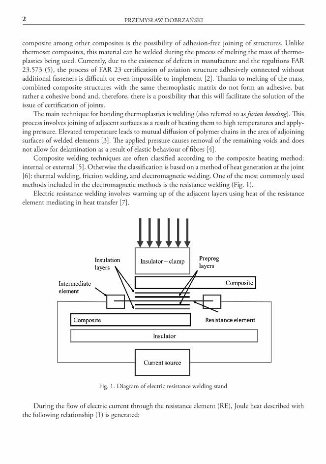
Electric resistance welding involves warming up of the adjacent layers using heat of the resistance element mediating in heat transfer [7].
Fig. 1. Diagram of electric resistance welding stand
During the flow of electric current through the resistance element (RE), Joule heat described with the following relationship (1) is generated:
BONDING OF HIGH TEMPERATURE THERMOPLASTIC CARBON COMPOSITES… 3
1)
where: Q - heat, R - conductor resistance, I - intensity of current flowing through the conductor, t - time.
This heat is then transferred to the adjacent layers of composite, and the melting process starts after temperature (glass transition temperature Tg for amorphous thermoplastics and melting point Tm for semi-crystalline thermoplastics) is exceeded. In addition, pressure is applied to the system to allow mutual diffusion. When the appropriate degree of melting is obtained, the heat source is cut off and the bond temperature starts to drop. Pressure is applied until the newly formed structure is cooled [8]. Unfortunately, the resistance element remains in the structure of the composite, which on the one hand may cause structural defects, while on the other hand allows heating up the bond, and thus improving or repairing the bond. The advantages of this type of technology is simple instrumentation, easy prepa-ration of welded composite surfaces and the ability to join large areas [7, 8].
From amongst the following technologies: resistance welding, induction and ultrasonic welding, the former is the most commonly used. In relation to the ultrasonic or induction welding, the electric resistance welding requires the least power and a small amount of energy [19]:
–– ultrasonic welding requires 1,980 W and 0.7 kJ,–– induction welding: 420 W and 23 kJ,–– electric resistance welding: 90 and 1.8 kJ.
This technology is used in the aviation industry, where the most known application is in the lead-ing edge of Airbus A340-500/600 and A380. By applying the technology of thermoplastic composite bonding using electric resistance welding technology, it was possible to reduce mass by more than 20% with a slight increase in cost compared to aluminium [9].
2. ELECTRIC RESISTANCE WELDING PROCESS2.1. Electric resistance welding stand
A diagram of a typical electric resistance welding stand is presented in Fig. 1. A package of layers consisting of a resistance element (RE) and the surrounding clean layers of thermoplastic or prepreg is introduced between the bonded composite elements. Those layers allow for filling in the mesh with composite matrix and complete the outflowing molten matrix. Sometimes, also an additional insu-lating layer in the form of glass-reinforced preimpregnation agent is used. The resistance element is connected with electric system using intermediate elements. The entire system is thermally insulated from the bottom using the table holding the instruments and from the top with a clamp (Fig. 1). The insulation allows for quick and local heating up of the matrix. Typical parameters of the electric resis-tance welding are presented in Table 1 [10].
4 PRZEMYSŁAW DOBRZAŃSKI
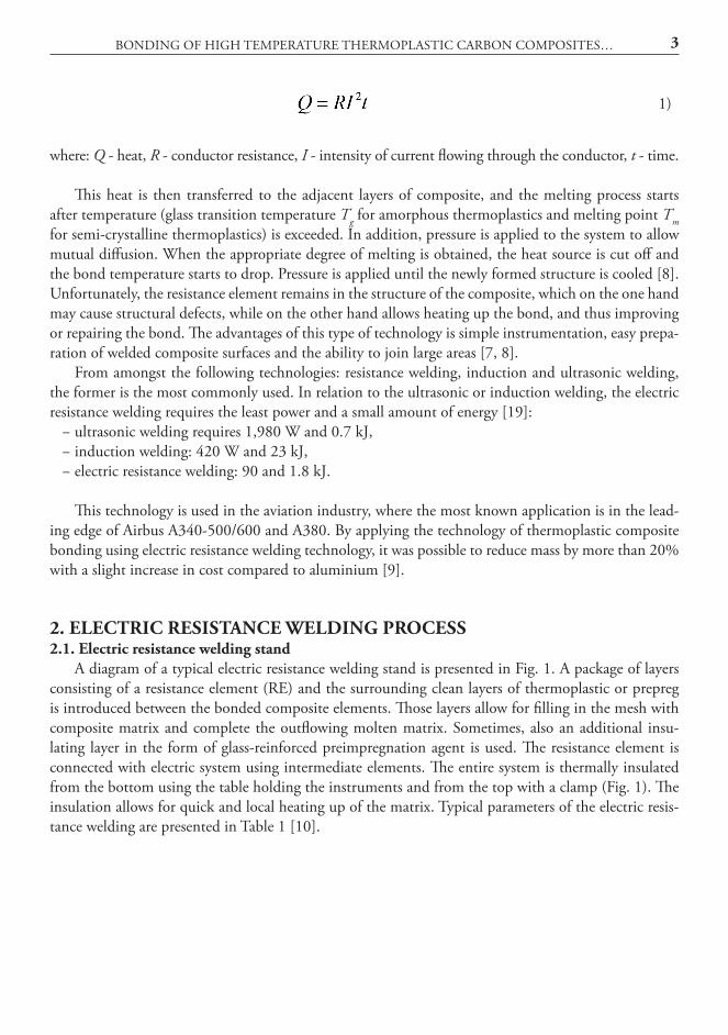
Table 1. Typical parameters of the electric resistance welding process
2.2. Types of resistance elementsThe primary issue to be determined before starting the welding process is the selection of the
heat-generating resistance element. Most often, the following two materials are used: carbon fibre and metal mesh. In the 1980s and 1990s, due to compatibility of the material with reinforcement, the carbon fibre was the most commonly used material [11]. Currently wire mesh is more frequently met in literature.
In the case of the use of carbon fibres as the material of the resistance element, the same fibre or prepreg from which the bonded elements are manufactured should be used. In the case of the use of a part of the prepreg layer, the ends of reinforcement must be insulated from the matrix to allow for their connection to power supply. Two types of fibres are used: unidirectional and bidirectional fabrics. Better mechanical properties of the joint and a more even temperature distribution was achieved by applying fibres in the form of fabric than a unidirectional material (which has been shown in lap shear strength — SLS tests, where strength was higher by 69%, while the critical energy release rate GIC for the fabric was even 179% of the value for a unidirectional material [12]). However, this method has some limitations and is difficult to apply [11]. Carbon fibres are brittle. Too much pressure resulted in damage to the fibres, reducing the conductivity of the bond. As a result, attempts were made to use metal resistance elements.
An example of use of carbon fibres as the resistance element may be found in article [13], where two parts made of a carbon preimpregnation agent with polyetherimide (PEI) were bonded. The resistance element was made of a prepreg single layer with 42% matrix content. In the first place, the material was compressed in the press under the pressure of 0.6 MPa in order to improve the layer consolidation and increase its smoothness [13]. Then the compressed layer was placed between two very thin layers of raw PEI (76 μm thick), and once again compressed under pressure of 1.9 MPa. Additional layers of raw thermoplastic complement the rough surface and provides a larger amount of material to the mutual diffusion process. As a result, it is possible to achieve up to 30% more durable bond [8]. In order to supply electricity to carbon fibres, the PEI matrix was etched using dichloromethane on the sides of the resistance element. A similar procedure was used in [8].
The attempts to bond the material using steel mesh have shown that they are simpler to use, and the matrix exhibits good adhesion to the mesh material [14]. Heat distribution is more even and the welding process is more stable. Thanks to this, the “window” of the technological process is wider. The processing window is defined as a set of process parameters allowing for obtaining 90% of the strength of the reference sample (bonded in the press during the process, such as thermoforming) [8]. The difficulty in using the steel mesh may result from thermal expansion, the mass of the material, corrosivity and, above all, the drop in current as a result of contact of the RE with carbon fibres in the composite. This may be resolved by using an insulating layer [14], for example glass. All of this leads to the possibility of obtaining greater strength of the bond compared to using a resistance element in the
BONDING OF HIGH TEMPERATURE THERMOPLASTIC CARBON COMPOSITES… 5
form of carbon fibres [14]. When choosing the mesh, apart its material, it is necessary to take into account wire diameter and the size of the mesh [11]. When comparing wire with diameter of 0.036÷0.114 mm and mesh size (0.043÷0.152 mm), it was found that the greatest strength, measured on a single lap joint - Fig. 2), was obtained for the diameter of 0.04 mm and mesh size of 0.09 mm [11].
The example of the stainless steel mesh used in the welding process can be found in article [15]. Such mesh was made of alloy 304L. Diameter of the wire was 0.2 mm, thickness of the mesh was 0.4 mm, while mesh size was 0.858 mm. Then, mesh was located between six layers of 0.06 mm thick PEI or alternately between four 0.09 mm PPS layers.
2.3. Connecting of resistance elements with electrical systemRegardless of the selection of material of the resistance element, the difficulty in accomplishing the
welding process lies with its connection to the electrical system. For this purpose, an intermediate ele-ment (IE) is used. The overview of the applied method has been presented in article [13]. Starting from the simplest – direct clamping on the prepreg or on composite fibres, to more complex, for example pouring of liquid metal on the prepreg or clamping on the conductive elements ultrasonically welded with the resistance elements. Increasing the resistance on the bond causes that more and more power is consumed for the generation of heat in connection of RE with the system, and not for the proper bonding of composite elements. Therefore, it is necessary to strive for minimizing the resistance of RE-IE bond [8]. Regardless of the method used, the aim is to provide fixing technology providing ease and repeatability of production. In addition, the elements intermediating in transmission of current from electrical wiring to the RE should be located possibly close to the connected structures so as to re-duce the effect of overheating of the material around the bonding edge caused be uneven speed of prop-agation of heat of the RE in the composite (the effect has been described further in this article) [16].
2.4. Composite elements welding processThe thermal process of welding is carried out as a result of dissipation of electrical energy in the
form of heat during conduction of current through the conductor - Joule heat described with the equation (1). Time and electrical current can be used to control the thermal process.. Resistance of the RE is uncontrolled and varies along with the change in temperature. The decrease in resistance along with change in temperature may reach a different level. For example, for a composite with carbon reinforcement and PEEK (Polyether Ether Ketone) matrix, this value may be 6.3% of the decrease in resistance at 340°C. The decrease in the resistance of carbon fibre may depend on the type of the layer (unidirectional or bidirectional) and the size of the element. In a PEI material, depending on the type of the layer and the size of the welded element, the decrease in resistance was in the range 7÷13% [13] (3.5% per 100°C). For simplicity, for carbon fibres, it can be assumed that the electrical resistance de-creases linearly along with the increasing temperature [15]. The inverse relationship was recorded for mesh made of stainless steel, where electrical resistance increases linearly along with the temperature rise [15]. In addition, if the mesh was not impregnated with matrix in the initial stage of the welding process, the relationship can be non-linear. This corresponds to the effect of impregnation of the steel mesh with matrix.
Apart from the decline in energy in the parts of the system other than the resistance element, elec-tric power is described by the equation (2) [13]:
6 PRZEMYSŁAW DOBRZAŃSKI
2)
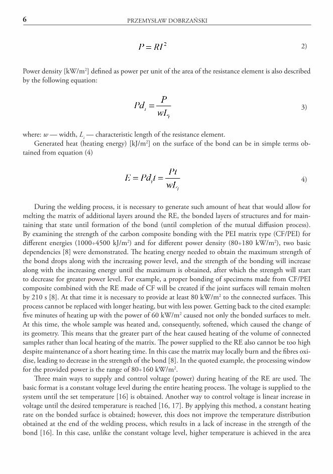
Power density [kW/m2] defined as power per unit of the area of the resistance element is also described by the following equation:
3)
where: w — width, Li — characteristic length of the resistance element.Generated heat (heating energy) [kJ/m2] on the surface of the bond can be in simple terms ob-
tained from equation (4)
4)
During the welding process, it is necessary to generate such amount of heat that would allow for melting the matrix of additional layers around the RE, the bonded layers of structures and for main-taining that state until formation of the bond (until completion of the mutual diffusion process). By examining the strength of the carbon composite bonding with the PEI matrix type (CF/PEI) for different energies (1000÷4500 kJ/m2) and for different power density (80÷180 kW/m2), two basic dependencies [8] were demonstrated. The heating energy needed to obtain the maximum strength of the bond drops along with the increasing power level, and the strength of the bonding will increase along with the increasing energy until the maximum is obtained, after which the strength will start to decrease for greater power level. For example, a proper bonding of specimens made from CF/PEI composite combined with the RE made of CF will be created if the joint surfaces will remain molten by 210 s [8]. At that time it is necessary to provide at least 80 kW/m2 to the connected surfaces. This process cannot be replaced with longer heating, but with less power. Getting back to the cited example: five minutes of heating up with the power of 60 kW/m2 caused not only the bonded surfaces to melt. At this time, the whole sample was heated and, consequently, softened, which caused the change of its geometry. This means that the greater part of the heat caused heating of the volume of connected samples rather than local heating of the matrix. The power supplied to the RE also cannot be too high despite maintenance of a short heating time. In this case the matrix may locally burn and the fibres oxi-dise, leading to decrease in the strength of the bond [8]. In the quoted example, the processing window for the provided power is the range of 80÷160 kW/m2.
Three main ways to supply and control voltage (power) during heating of the RE are used. The basic format is a constant voltage level during the entire heating process. The voltage is supplied to the system until the set temperature [16] is obtained. Another way to control voltage is linear increase in voltage until the desired temperature is reached [16, 17]. By applying this method, a constant heating rate on the bonded surface is obtained; however, this does not improve the temperature distribution obtained at the end of the welding process, which results in a lack of increase in the strength of the bond [16]. In this case, unlike the constant voltage level, higher temperature is achieved in the area
BONDING OF HIGH TEMPERATURE THERMOPLASTIC CARBON COMPOSITES… 7
of the edge, and not in the middle of the connection [16]. The third technology is pulse welding. It consists in providing high power pulses for heating, for example 600 kW/m2 [18]. In comparison with constant control, by using this technology, it is possible to obtain more uniform temperature distribu-tion; however, due to the high voltage peaks, the resistance element may be easily damaged.
The welding time can be shorter even five times compared to the classic welding process as de-scribed above [10]. This allows for a reduction in local overheating of the material.
One of the primary requirements of the technology is good insulation of the system, preventing loss of heat of the system [7]. Heating of the material to a high temperature is accompanied by high heat loss by tooling. The lack of sufficient insulation of the system may prevent the possibility of obtaining sufficiently high temperature locally to ensure that melting is a local phenomenon only. In an extreme case, the connection may fail or too large volume of material may be heated, which may lead to its degradation. An example of the material used for insulation can be bakelite [7] or wooden [8] plates.
2.5. Pressure application in the electric resistance welding processTo carry out mutual diffusion, it is required to apply pressure [7]. The welding process can occur
in two ways: at constant pressure or with a constant displacement. Welding with a constant displacement does not require complicated equipment. The bond thick-
ness can be easily controlled. The difficulty may be posed by the lack of pressure control in the bond, which is variable due to a change in the phase of the melted material or thermal expansion. The maxi-mum pressure applied to the created joint is greater than the one established and applied at the begin-ning of the process. Excessive pressure may lead to leakage of the matrix, thus creating a dry, incorrect bond [13]. Too high or too low pressure at the early stages of the process can cause low strength of the joint. For example, to obtain the correct bonding of a CF/PEI composite, it was demonstrated, that the minimum pressure required to obtain the reference strength is 0.1 MPa. Pressure lower than specified during the layer-joining process is not sufficient to eliminate the elastic deformation of the fibre and outgassing of the bonding zone [8].
Implementation of the process with constant controlled pressure improves control of the process of joining layers of the material. However, this requires more complex instrumentation. The system providing pressure must be controlled in the feedback loop between the head and the instrumentation providing direct pressure [13]. Currently, most of modern research studies are carried out while main-taining the constant pressure.
Examples of literature describing the welding process using different methods of pressure are listed in Table 2.
Typically, regardless of the value of the applied pressure, voids are formed at the edges of the sam-ples (in the area of connection to power supply) within the RE and in the first layer adjacent to the RE. When the heated thermoplastic becomes liquid under the influence of the applied pressure, it leaks from the bond, leaving voids. In addition, local, on the side of the weld, lack of matrix causes decrease in pressure [11]. Depending on the applied pressure, this leakage can occur at a different time and with varying intensity. The phenomenon is also intensified by the uneven temperature distribution on the edges of the sample. A broader overview of the literature in this regard can be found in [7].
8 PRZEMYSŁAW DOBRZAŃSKI
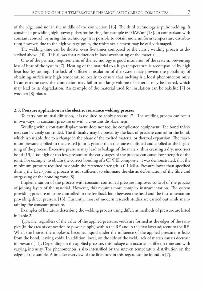
Table 2. Sample pressure parameters
Designations: PPS - Polyphenylene Sulfide, PEEK - Polyetheretherketone, CF - Carbon Fibre, GF - Glass Fibre
2.6. Distribution of temperature in the bond in the electric resistance welding processOne of the main difficulties of combining large structures is the uneven temperature distribution,
which causes local overheating of the material. This is due to the difference in heat flow between the side surface, and the inside of the resistance element [13] and higher preheating of the RE in zone be-fore the composite [8]. Uneven temperature distribution is the effect of changing the method of heat transfer of RE from conduction that occurs inside the composite to slower processes, such as radiation and free convection in the air around the edge of the structure [16]. The consequence of the phenom-enon may be local squeezing of the matrix out, loss of shape and size and contact of the resistance element with composite fibres. Contact of the RE with composite fibres increases the cross-sectional area of the conductor and decreases resistance, which in turn leads to a decrease in heating power of the resistance element and even greater differences in the bond (very high temperature at the edges and low- inside the bond). Too low temperature in the central part of the bonding area may not be suffi-cient to weld the material [13, 14]. Decrease in current can be recorded by a sudden drop in electrical resistance of the resistance element in time. This may be counteracted by increasing insulation of the resistance element from the composite fibres, e.g. by using a layer of the matrix without reinforcement (covering the bare resistance element) or layers of matrix with glass fibre [13, 14], (Fig.1). It should be added that connecting RE to the current source and the joined structure decreases temperature differ-ences in the bond [16].
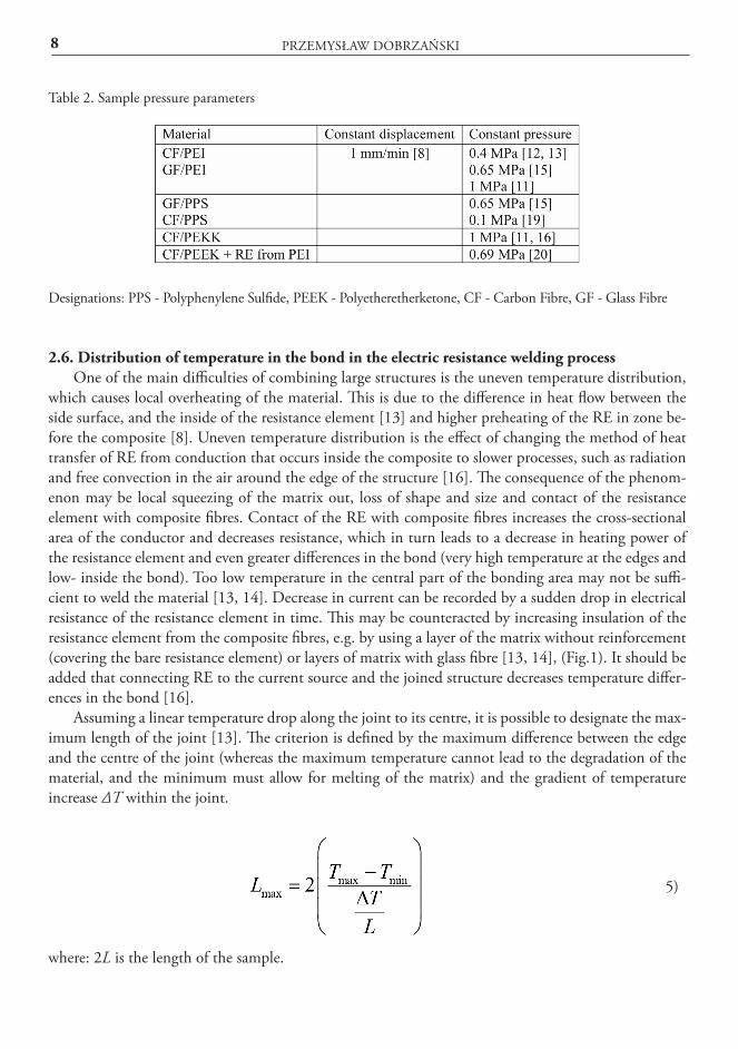
Assuming a linear temperature drop along the joint to its centre, it is possible to designate the max-imum length of the joint [13]. The criterion is defined by the maximum difference between the edge and the centre of the joint (whereas the maximum temperature cannot lead to the degradation of the material, and the minimum must allow for melting of the matrix) and the gradient of temperature increase ΔT within the joint.
5)
where: 2L is the length of the sample.
BONDING OF HIGH TEMPERATURE THERMOPLASTIC CARBON COMPOSITES… 9
Also, the change in the processing window along with a change of shape and dimensions of the connected elements, moulds and tooling may cause a difficulty. Due to the different rate of ther-mal processes, it may be necessary to redefine the processing window. One of the possible solutions to the presented difficulties is to control the temperature and time of the process using a feedback loop of current source connected with temperature measurement [15]. The temperature in the mid-dle of the weld without direct access can be measured indirectly by measuring the resistance of the temperature-dependent resistance element. Although the method allows for control of the temperature in the welding process, still knowledge on the temperature distribution in the created bond is required (due to the non-uniform temperature distribution). However, it allows for controlling the speed of heating and cooling, which can improve the weld properties [6].
2.7. Electric resistance welding methodsThe main parameters limiting distribution of the resistance-welded elements are: pressure level,
the required electric power supplied to the resistance elements, non-uniform temperature distribu-tion in the welding zone and loss of a part of electric current in the composite [13]. These difficulties can be overcome by welding the elements sequentially (sequential resistance welding — SRW). The technology relies on automated welding of successive, short sections of the bond instead of welding the whole bond in one operation [20]. Welding of small sections facilitates maintenance of even tem-perature distribution, less power is required and obtaining of the required pressure on smaller surface requires less feed force. It has been shown that the use of sequential welding for a long (30 cm) bond and comparing the strength SLS of the bond made in one process, higher strength is achieved. What is more, the bond is more uniform, and the cold spots and overheating are significantly reduced [20]. The latest technology is continuous electric resistance welding. More information on this topic can be found in works [21, 22].
2.8. Quality controlA correctly executed bond has the same strength as the connected material which was not sub-
jected to welding, but was entirely formed in a single process, for example pressing [8]. When using the pressing technology, a connection of two parts of composite is created with dimensions and shape of the selected bond strength test, i.e. the reference sample. When setting the strength of the reference sample, the maximum possible value of the strength of the bond is established. An example of a standard sample may be a single lap shear joint - SLS (ASTM D 1002), Fig. 2). Such an element allows for determining the shear strength determined during a tension test. If the samples welded and joined using a press obtain a similar strength, it is assumed that the welding process has been carried out correctly [13].
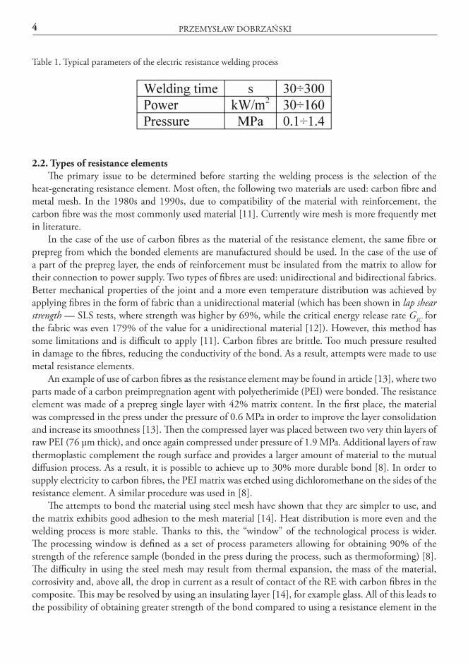
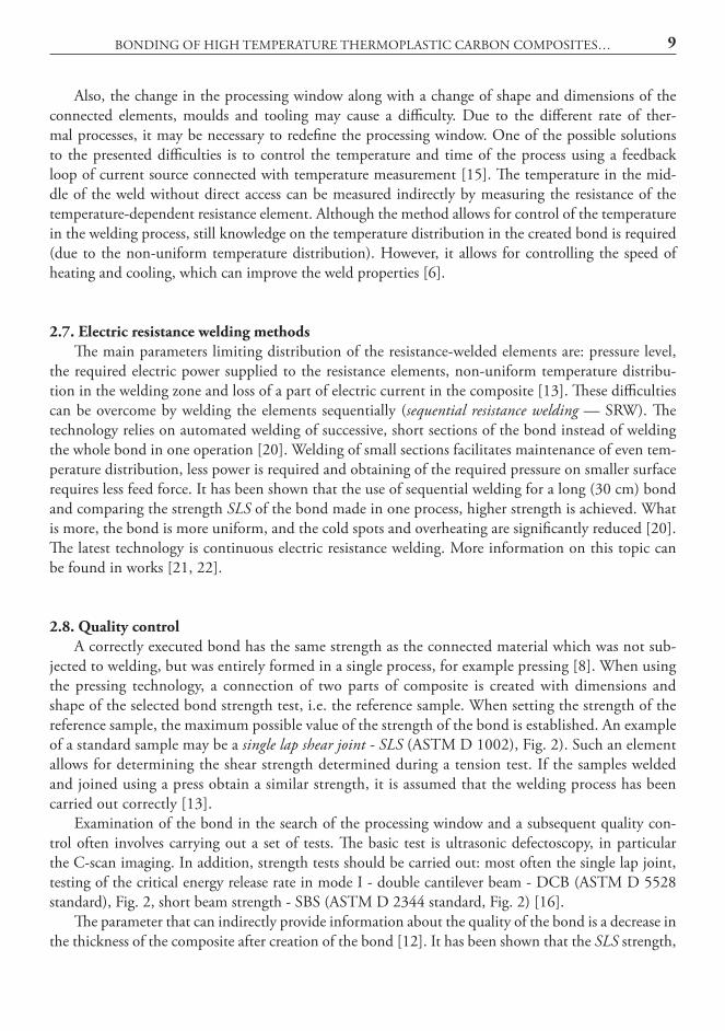
Examination of the bond in the search of the processing window and a subsequent quality con-trol often involves carrying out a set of tests. The basic test is ultrasonic defectoscopy, in particular the C-scan imaging. In addition, strength tests should be carried out: most often the single lap joint, testing of the critical energy release rate in mode I - double cantilever beam - DCB (ASTM D 5528 standard), Fig. 2, short beam strength - SBS (ASTM D 2344 standard, Fig. 2) [16].
The parameter that can indirectly provide information about the quality of the bond is a decrease in the thickness of the composite after creation of the bond [12]. It has been shown that the SLS strength,
10 PRZEMYSŁAW DOBRZAŃSKI
along with a reduction in the thickness of the bond, initially grows until the reference strength is obtained (the decrease in thickness was 0.5 mm). Then, with a greater reduction, the strength is main-tained at a similar level, but lower than the standard strength.
Fig. 2. Strength tests used to verify the quality of the bond
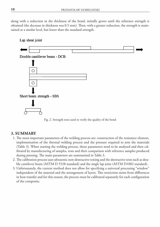
3. SUMMARY1. The most important parameters of the welding process are: construction of the resistance element,
implementation of the thermal welding process and the pressure required to join the materials (Table 3). When starting the welding process, those parameters need to be analysed and then cal-ibrated by manufacturing of samples, tests and their comparison with reference samples produced during pressing. The main parameters are summarised in Table 3.
2. The calibration process uses ultrasonic non-destructive testing and the destructive tests such as dou-ble cantilever beam (ASTM D 5528 standard) and the single lap joint (ASTM D1002 standard).
3. Unfortunately, the current method does not allow for specifying a universal processing “window” independent of the material and the arrangement of layers. This restriction stems from differences in heat transfer and for this reason, the process must be calibrated separately for each configuration of the composite.
BONDING OF HIGH TEMPERATURE THERMOPLASTIC CARBON COMPOSITES… 11
Table 3. Main characteristics and parameters of the electric resistance welding
REFERENCES[1] Brosius, D., 2015, “Thermosets vs. thermoplastics: Is the battle over?,” Compos. World.[2] Society of Automotive Engineers, and National Institute for Aviation Research (U.S.), eds., 2012,
Composite materials handbook Volume 3, SAE International on behalf of CMH-17, a division of Wichita State University, Warrendale, Pa.
[3] Deng, S., Djukic, L., Paton, R., and Ye, L., 2015, “Thermoplastic–epoxy interactions and their potential applications in joining composite structures – A review,” Compos. Part Appl. Sci. Manuf., 68, pp. 121–132.
[4] Campbell, F. C., 2004, Manufacturing processes for advanced composites, Elsevier, New York.[5] Liu, H., and Rowe, K., 2014, “Joining of high performance thermoplastic composite for next
generation aerospace structure components,” SAMPE, Seattle.[6] Yousefpour, A., Hojjati, M., and Immarigeon, J.-P., 2004, “Fusion Bonding/Welding of Thermo-
plastic Composites,” J. Thermoplast. Compos. Mater., 17(4), pp. 303–341.
12 PRZEMYSŁAW DOBRZAŃSKI
[7] Stavrov, D., and Bersee, H. E. N., 2005, “Resistance welding of thermoplastic composites-an overview,” Compos. Part Appl. Sci. Manuf., 36(1), pp. 39–54.
[8] Hou, M., Ye, L., and Mai, Y.-W., 1999, “An Experimental Study of Resistance Welding of Carbon Fibre Fabric Reinforced Polyetherimide (CF Fabric/PEI) Composite Material,” Appl. Compos. Mater., 6(1), pp. 35–49.
[9] 2006, “Thermoplastic composites gain leading edge on the A380,” High-Perform. Compos.[10] Ageorges, C., Ye, L., and Hou, M., 2001, “Advances in fusion bonding techniques for joining ther-
moplastic matrix composites: a review,” Compos. Part Appl. Sci. Manuf., 32(6), pp. 839–857.[11] Dubé, M., Hubert, P., Gallet, J. N., Stavrov, D., Bersee, H. E., and Yousefpour, A., 2012, “Metal
mesh heating element size effect in resistance welding of thermoplastic composites,” J. Compos. Mater., 46(8), pp. 911–919.
[12] Ageorges, C., Ye, L., and Hou, M., 2000, “Experimental investigation of the resistance welding of thermoplastic-matrix composites. Part II: optimum processing window and mechanical perfor-mance,” Compos. Sci. Technol., 60(8), pp. 1191–1202.
[13] Ageorges, C., Ye, L., and Hou, M., 2000, “Experimental investigation of the resistance welding for thermoplastic-matrix composites. Part I: heating element and heat transfer,” Compos. Sci. Technol., 60(7), pp. 1027–1039.
[14] Hou, M., Yang, M., Beehag, A., Mai, Y.-W., and Ye, L., 1999, “Resistance welding of carbon fibre reinforced thermoplastic composite using alternative heating element,” Tenth Int. Conf. Compos. Struct., 47(1–4), pp. 667–672.
[15] Villegas, I. F., and Bersee, H. E., 2015, “Characterisation of a metal mesh heating element for closed-loop resistance welding of thermoplastic composites,” J. Thermoplast. Compos. Mater., 28(1), pp. 46–65.
[16] Dubé, M., Hubert, P., Yousefpour, A., and Denault, J., 2007, “Resistance welding of thermoplastic composites skin/stringer joints,” Compos. Part Appl. Sci. Manuf., 38(12), pp. 2541–2552.
[17] Yousefpour, A., Simard, M., Octeau, M. A., and Hojjati, M., 2005, “Process optimization of re-sistance welded thermoplastic composites using metal mesh heating elements,” Long Beach CA.
[18] Arias, M., and Ziegmann, G., 1996, “The Impulse Resistance Welding: A new Technique for Join-ing Advanced Thermoplastic Composite Parts,” Anaheim, California, pp. 1361–1371.
[19] Villegas, I. F., Moser, L., Yousefpour, A., Mitschang, P., and Bersee, H. E., 2012, “Process and performance evaluation of ultrasonic, induction and resistance welding of advanced thermoplastic composites,” J. Thermoplast. Compos. Mater.
[20] McKnight, S. H., Holmes, S. T., Gillespie, J. W., Lambing, C. L. T., and Marinelli, J. M., 1997, “Scaling issues in resistance-welded thermoplastic composite joints,” Adv. Polym. Technol., 16(4), pp. 279–295.
[21] Yousefpour, A., and Octeau, “Resistance welding of thermoplastics. US20090032184 A1. Cana-da; 2009.”
[22] Shi, H., Villegas, I. F., Octeau, M.-A., Bersee, H. E. N., and Yousefpour, A., 2015, “Continuous resistance welding of thermoplastic composites: Modelling of heat generation and heat transfer,” Compos. Part Appl. Sci. Manuf., 70, pp. 16–26.
BONDING OF HIGH TEMPERATURE THERMOPLASTIC CARBON COMPOSITES… 13
ŁĄCZENIE KOMPOZYTÓW WĘGLOWYCH NA OSNOWIE Z WYSOKOTEMPERATUROWYCH
TERMOPLASTÓW Z ZASTOSOWANIEM TECHNIKI ZGRZEWANIA ELEKTROOPOROWEGO
Streszczenie W artykule zaprezentowano aktualny stan wiedzy dotyczącej łączenia kompozytów o spoiwie
termoplastycznym wzmacnianych włóknami syntetycznymi z użyciem technologii elektrooporowej. Przedstawiono proces ich zgrzewania oraz trudności związane z realizacją procesu i kontrolą jako-ści wytworzonego połączenia. Opisano budowę typowego stanowiska do zgrzewania kompozytów o spoiwie termoplastycznym. Scharakteryzowano podstawowe elementy technologii zgrzewania: bu-dowę elementu oporowego, realizację procesu cieplnego zgrzewania oraz realizację docisku wyma-ganego do połączenia materiałów. W artykule przedstawiono zakres wymaganej kalibracji procesu technologicznego dokonywanej na podstawie badań wytrzymałościowych (próbki jednozakładko-wej, podwójnej belki wspornikowej oraz zginanej krótkiej belki) oraz diagnostyki połączeń zgrzewa-nych metodą ultradźwiękową.
Słowa kluczowe: termoplasty, zgrzewanie elektrooporowe, łączenie kompozytów z termoplastów.