Embed Size (px)
Citation preview

Bomgar Corporation B200™ and B300™ Remote Support Appliances Firmware Version: 3.2.2FIPS; Software Version: 10.6.2FIPS; Hardware Versions: B200, B300, and B300 r1
FIPS 140-2 Non-Proprietary Security Policy FIPS Security Level: 2 Document Version: 0.9
Prepared for: Prepared by:
Bomgar Corporation Corsec Security, Inc.
578 Highland Colony Parkway Paragon Centre, Suite 300 Ridgeland, MS 39157 United States of America
13135 Lee Jackson Memorial Highway Suite 220
Fairfax, VA 22033 United States of America
Phone: +1 (601) 519-0123 Phone: +1 (703) 267-6050 http://www.bomgar.com http://www.corsec.com

Security Policy, Version 0.8 August 11, 2011
Bomgar B200™ and B300™ Remote Support Appliances Page 2 of 29
© 2011 Bomgar Corporation This document may be freely reproduced and distributed whole and intact including this copyright notice.
Table of Contents
1 INTRODUCTION ................................................................................................................... 4
1.1 PURPOSE ................................................................................................................................................................ 4
1.2 REFERENCES .......................................................................................................................................................... 4
1.3 DOCUMENT ORGANIZATION ............................................................................................................................ 4
2 B200™ AND B300™ REMOTE SUPPORT APPLIANCES .................................................. 5
2.1 OVERVIEW ............................................................................................................................................................. 5
2.2 MODULES SPECIFICATION ................................................................................................................................... 7
2.3 MODULE INTERFACES .......................................................................................................................................... 8
2.4 ROLES AND SERVICES ......................................................................................................................................... 11
2.4.1 Crypto-Officer Role.............................................................................................................................................. 11
2.4.2 Instance-Admin Role ........................................................................................................................................... 11
2.4.3 Instance-User Role .............................................................................................................................................. 11
2.4.4 Services ................................................................................................................................................................... 11
2.4.5 Unauthenticated Operator Services .............................................................................................................. 13
2.4.6 Authentication Mechanism ............................................................................................................................... 13
2.5 PHYSICAL SECURITY ........................................................................................................................................... 13
2.6 OPERATIONAL ENVIRONMENT ......................................................................................................................... 13
2.7 CRYPTOGRAPHIC KEY MANAGEMENT ............................................................................................................ 13
2.8 EMI/EMC ............................................................................................................................................................ 15
2.9 SELF-TESTS .......................................................................................................................................................... 16
2.9.1 Power-Up Self-Tests ............................................................................................................................................ 16
2.9.2 Conditional Self-Tests ......................................................................................................................................... 16
2.10 MITIGATION OF OTHER ATTACKS .................................................................................................................. 16
3 SECURE OPERATION ......................................................................................................... 17
3.1 INITIAL SETUP ...................................................................................................................................................... 17
3.1.1 B200 Hardware Setup ...................................................................................................................................... 17
3.1.2 B200 Label Inspection ....................................................................................................................................... 17
3.1.3 B300 Hardware Setup ...................................................................................................................................... 18
3.1.4 B300 Label Inspection and Application ....................................................................................................... 19
3.1.5 Firmware/Software Version Verification ....................................................................................................... 22
3.2 FIPS MODE COMPLIANCE ................................................................................................................................. 22
3.3 CRYPTO-OFFICER GUIDANCE .......................................................................................................................... 25
3.3.1 Management ........................................................................................................................................................ 25
3.3.2 Status Monitoring ................................................................................................................................................ 25
3.3.3 Zeroization ............................................................................................................................................................ 26
3.4 INSTANCE-ADMIN AND INSTANCE-USER GUIDANCE ................................................................................... 26
4 ACRONYMS .......................................................................................................................... 27
Table of Figures FIGURE 1 – BOMGAR B200 (TOP) AND B300 (BOTTOM) ................................................................................................... 5
FIGURE 2 – TYPICAL DEPLOYMENT ......................................................................................................................................... 6
FIGURE 3 – BLOCK DIAGRAM FOR B200 WITH CRYPTOGRAPHIC BOUNDARY ............................................................... 8
FIGURE 4 – BLOCK DIAGRAM FOR B300 WITH CRYPTOGRAPHIC BOUNDARY ................................................................ 8
FIGURE 5 – FRONT AND REAR VIEW OF B200 ...................................................................................................................... 9
FIGURE 6 – FRONT AND REAR VIEW OF B300 ...................................................................................................................... 9
FIGURE 7 – TAMPER SEAL APPLIED TO THE TOP, OVERLAPPING THE GALVANIZED METAL COVER AND THE FRONT
PANEL .............................................................................................................................................................................. 18
FIGURE 8 – TAMPER SEAL APPLIED TO THE REAR, OVERLAPPING THE GALVANIZED METAL COVER AND REAR STEEL
BEZEL............................................................................................................................................................................... 18

Security Policy, Version 0.8 August 11, 2011
Bomgar B200™ and B300™ Remote Support Appliances Page 3 of 29
© 2011 Bomgar Corporation This document may be freely reproduced and distributed whole and intact including this copyright notice.
FIGURE 9 – REAR METALLIC BEZEL SEAL (LEFT) AND SEALED TOP COVER (RIGHT) ....................................................... 20
FIGURE 10 – SEALED FRONT BEZEL TO CHASSIS TOP (LEFT) AND SEALED FRONT BEZEL TO CHASSIS BOTTOM
(RIGHT) .......................................................................................................................................................................... 20
FIGURE 11– SEALED TOP CHASSIS TO LEFT POWER SUPPLY (LEFT) AND SEALED TOP CHASSIS TO RIGHT POWER
SUPPLY (RIGHT) ............................................................................................................................................................. 20
FIGURE 12 – IP CONFIGURATION PAGE ............................................................................................................................. 21
FIGURE 13 – SSL CONFIGURATION PAGE .......................................................................................................................... 22
FIGURE 14 – STATUS BASICS PAGE ...................................................................................................................................... 23
FIGURE 15 – ADVANCED SUPPORT PAGE ........................................................................................................................... 24
FIGURE 16 – SECURITY PAGE ................................................................................................................................................ 24
FIGURE 17 – SUPPORT PAGE ................................................................................................................................................. 25
List of Tables TABLE 1 – SECURITY LEVEL PER FIPS 140-2 SECTION .......................................................................................................... 6
TABLE 2 – PHYSICAL PORTS AND LOGICAL INTERFACES ..................................................................................................... 9
TABLE 3 – LED DESCRIPTIONS............................................................................................................................................. 10
TABLE 4 – MAPPING OF AUTHENTICATED OPERATOR SERVICES TO INPUTS, OUTPUTS, CSPS, AND TYPE OF
ACCESS ........................................................................................................................................................................... 11
TABLE 5 – UNAUTHENTICATED OPERATOR SERVICE ....................................................................................................... 13
TABLE 6 – AUTHENTICATION MECHANISM USED BY THE MODULES ............................................................................. 13
TABLE 7 – FIPS-APPROVED ALGORITHM IMPLEMENTATIONS .......................................................................................... 14
TABLE 8 – LIST OF CRYPTOGRAPHIC KEYS, CRYPTOGRAPHIC KEY COMPONENTS, AND CSPS ................................. 15
TABLE 9 – ACRONYMS .......................................................................................................................................................... 27
Security Policy, Version 0.8 August 11, 2011
Bomgar B200™ and B300™ Remote Support Appliances Page 4 of 29
© 2011 Bomgar Corporation This document may be freely reproduced and distributed whole and intact including this copyright notice.
1 Introduction
1.1 Purpose This is a non-proprietary Cryptographic Module Security Policy for the B200™ and B300™ Remote
Support Appliances from Bomgar Corporation. This Security Policy describes how the B200™ and
B300™ Remote Support Appliances meet the security requirements of FIPS1 140-2 and how to run the
modules in a secure FIPS 140-2 mode. This policy was prepared as part of the Level 2 FIPS 140-2
validation of the modules.
FIPS 140-2 – Security Requirements for Cryptographic Modules details the U.S. and Canadian
Government requirements for cryptographic modules. More information about the FIPS 140-2 standard
and validation program is available on the Cryptographic Module Validation Program (CMVP) website,
which is maintained by the National Institute of Standards and Technology (NIST) and the Communication
Security Establishment Canada (CSEC): http://csrc.nist.gov/groups/STM/cmvp.
The B200™ and B300™ Remote Support Appliances are referred to in this document as Bomgar
appliances, the cryptographic modules, or the modules.
1.2 References This document deals only with operations and capabilities of the modules in the technical terms of a FIPS
140-2 cryptographic module security policy. More information is available on the modules from the
following sources:
• The Bomgar website (http://www.bomgar.com/fips) contains information on the full line of
products from Bomgar Corporation.
• The CMVP website (http://csrc.nist.gov/groups/STM/cmvp/documents/140-1/140val-all.htm)
contains contact information for individuals to answer technical or sales-related questions for the
modules.
1.3 Document Organization The Security Policy document is one document in a FIPS 140-2 Submission Package. In addition to this
document, the Submission Package contains:
• Vendor Evidence document
• Finite State Model
• Other supporting documentation as additional references
This Security Policy and the other validation submission documentation were produced by Corsec Security,
Inc. under contract to Bomgar Corporation. With the exception of this Non-Proprietary Security Policy, the
FIPS 140-2 Validation Documentation is proprietary to Bomgar Corporation and is releasable only under
appropriate non-disclosure agreements. For access to these documents, please contact Bomgar
Corporation.
1 FIPS – Federal Information Processing Standard

Security Policy, Version 0.8 August 11, 2011
Bomgar B200™ and B300™ Remote Support Appliances Page 5 of 29
© 2011 Bomgar Corporation This document may be freely reproduced and distributed whole and intact including this copyright notice.
2 B200™ and B300™ Remote Support Appliances
2.1 Overview Bomgar Corporation specializes in appliance-based solutions for remote support. Their remote support
appliances give support technicians secure remote control of computers over the Internet, LAN2, or WAN
3.
The software works through firewalls with no pre-installed client on the remote computer. With the
Bomgar Remote Support Appliances, a support technician can see the screen and control the system
virtually as if physically present.
Figure 1 – Bomgar B200 (top) and B300 (bottom)
The B200™ and B300™ Remote Support Appliances (shown in Figure 1 above) enable the use of remote
support in multiple areas of an organization in a way that is secure, integrated and manageable. The
Bomgar appliances can integrate with LDAP4 for secure user management, prevent sensitive data from
being routed outside the organization, and support extensive auditing and recording of support sessions.
The logging is performed by the Bomgar appliances, which allows for the review of all Customer and
Support Representative interactions, including playback of all desktop screen data. The appliances also
integrate with leading systems management and identity management solutions and include an Application
Programming Interface (API) for deeper integration. With Bomgar, support managers can create support
teams, customize queues, and report on all support activities. Network administrators can also monitor the
Bomgar appliances using Simple Network Management Protocol (SNMP).
The Bomgar appliances enable remote access to multiple common operating systems, including various
Linux distributions. They also enable remote control of various kinds of systems, including laptops,
desktops, servers, kiosks, point-of-sale systems, smartphones, and network devices.
The Bomgar appliances can work over internal and extended networks and can be internet-accessible. This
allows support organizations to reduce less effective means of support by driving requests through custom
support portals hosted on the appliances. The Bomgar appliances can route support requests to the
appropriate technician or team and mediate connections between Customers and Support Representatives,
allowing chat sessions, file downloads/uploads, screen-sharing, remote control of desktops, and access to
system and diagnostic information.
To enable the functionality described above, Bomgar has implemented architecture that places the Bomgar
appliances at the center of all communications (see Figure 2 below for a typical deployment scenario). The
Bomgar appliances provide a platform upon which one or more support sites are constructed. Sites
represent individual help centers, and multiple sites can be set up to support multiple departments or groups
2 LAN – Local Area Network 3 WAN – Wide Area Network 4 LDAP – Lightweight Directory Access Protocol
Security Policy, Version 0.8 August 11, 2011
Bomgar B200™ and B300™ Remote Support Appliances Page 6 of 29
© 2011 Bomgar Corporation This document may be freely reproduced and distributed whole and intact including this copyright notice.
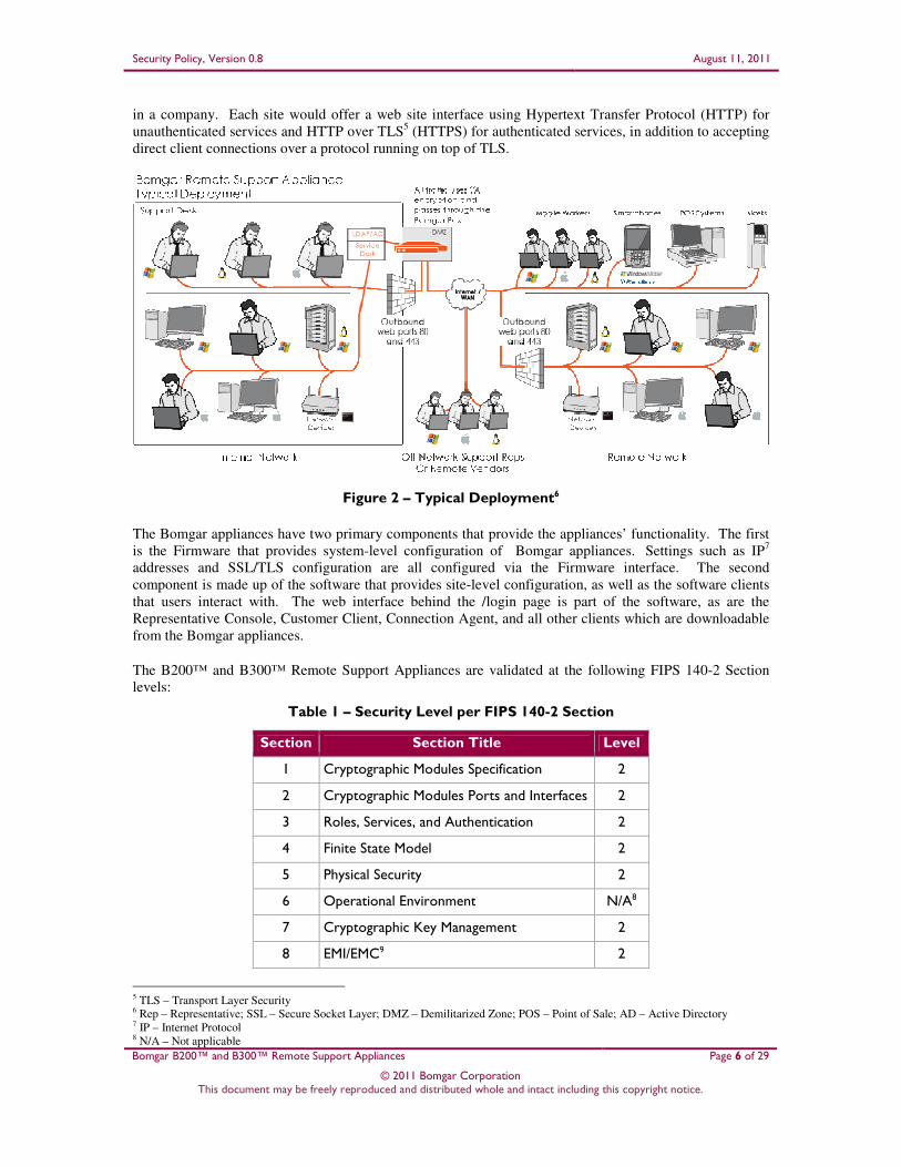
in a company. Each site would offer a web site interface using Hypertext Transfer Protocol (HTTP) for
unauthenticated services and HTTP over TLS5 (HTTPS) for authenticated services, in addition to accepting
direct client connections over a protocol running on top of TLS.
Figure 2 – Typical Deployment6
The Bomgar appliances have two primary components that provide the appliances’ functionality. The first
is the Firmware that provides system-level configuration of Bomgar appliances. Settings such as IP7
addresses and SSL/TLS configuration are all configured via the Firmware interface. The second
component is made up of the software that provides site-level configuration, as well as the software clients
that users interact with. The web interface behind the /login page is part of the software, as are the
Representative Console, Customer Client, Connection Agent, and all other clients which are downloadable
from the Bomgar appliances.
The B200™ and B300™ Remote Support Appliances are validated at the following FIPS 140-2 Section
levels:
Table 1 – Security Level per FIPS 140-2 Section
Section Section Title Level
1 Cryptographic Modules Specification 2
2 Cryptographic Modules Ports and Interfaces 2
3 Roles, Services, and Authentication 2
4 Finite State Model 2
5 Physical Security 2
6 Operational Environment N/A8
7 Cryptographic Key Management 2
8 EMI/EMC9 2
5 TLS – Transport Layer Security 6 Rep – Representative; SSL – Secure Socket Layer; DMZ – Demilitarized Zone; POS – Point of Sale; AD – Active Directory 7 IP – Internet Protocol 8 N/A – Not applicable

Security Policy, Version 0.8 August 11, 2011
Bomgar B200™ and B300™ Remote Support Appliances Page 7 of 29
© 2011 Bomgar Corporation This document may be freely reproduced and distributed whole and intact including this copyright notice.
Section Section Title Level
9 Self-tests 2
10 Design Assurance 2
11 Mitigation of Other Attacks N/A
2.2 Modules Specification The B200™ and B300™ Remote Support Appliances (running Firmware version 3.2.2FIPS and Software
version 10.6.2FIPS on Hardware versions B200, B300 or B300 r1) are multi-chip standalone modules that
meet overall Level 2 FIPS 140-2 requirements.
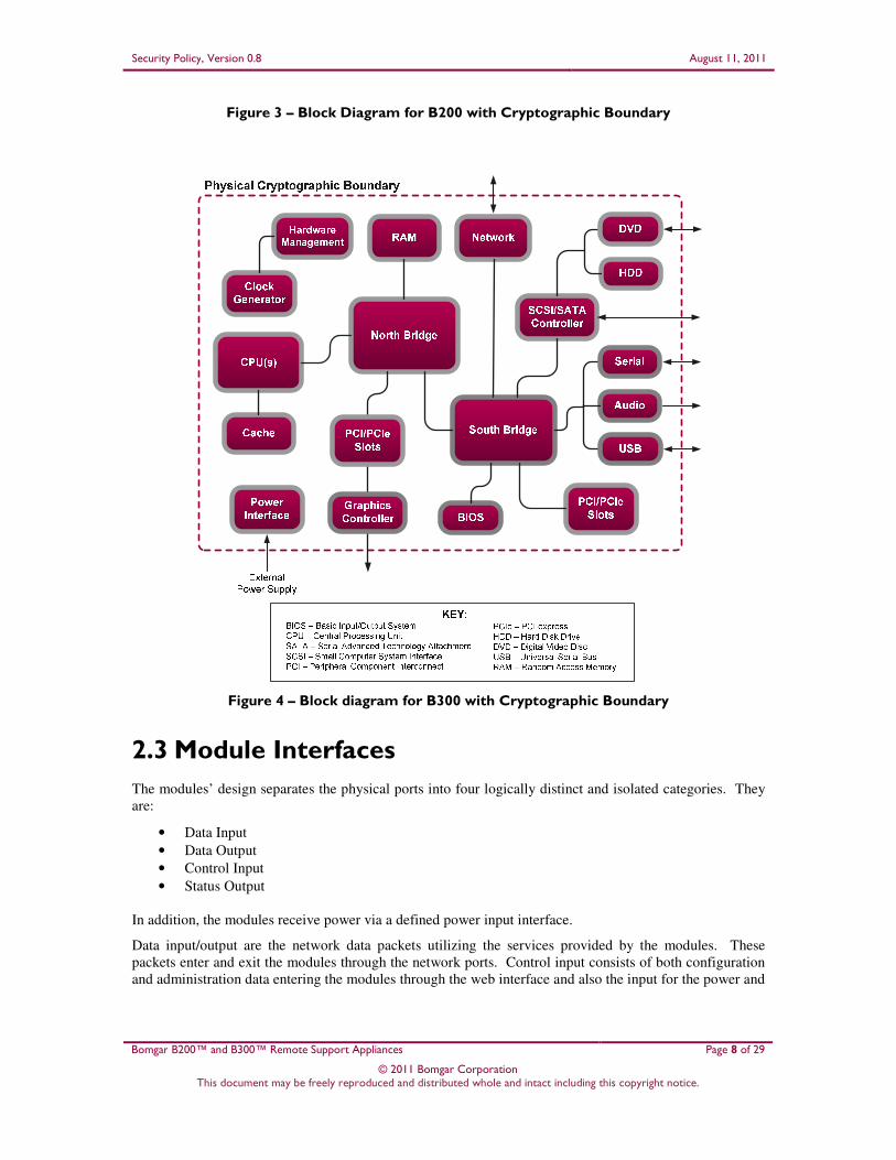
Physically, the modules are composed of the components of a standard server platform. Figure 3 and
Figure 4 show a block diagram for the B200 and B300 respectively and identify the various components,
connections, and information flows. The cryptographic boundary of the modules (denoted by the dotted
lines in Figure 3 and Figure 4) is defined by the outer case of each appliance, which surrounds the complete
set of hardware, firmware, and software components. Note that, though Figure 4 shows a single hard disk,
the B300 can support up to four hard disks to support RAID10
functionality. Additionally, please note that
the B300 power supply is not included the within the cryptographic boundary.
9 EMI/EMC – Electromagnetic Interference / Electromagnetic Compatibility 10 RAID – Redundant Array of Independent Disks
Security Policy, Version 0.8 August 11, 2011
Bomgar B200™ and B300™ Remote Support Appliances Page 8 of 29
© 2011 Bomgar Corporation This document may be freely reproduced and distributed whole and intact including this copyright notice.
Figure 3 – Block Diagram for B200 with Cryptographic Boundary
Figure 4 – Block diagram for B300 with Cryptographic Boundary
2.3 Module Interfaces
The modules’ design separates the physical ports into four logically distinct and isolated categories. They
are:
• Data Input
• Data Output
• Control Input
• Status Output
In addition, the modules receive power via a defined power input interface.
Data input/output are the network data packets utilizing the services provided by the modules. These
packets enter and exit the modules through the network ports. Control input consists of both configuration
and administration data entering the modules through the web interface and also the input for the power and
Security Policy, Version 0.8 August 11, 2011
Bomgar B200™ and B300™ Remote Support Appliances Page 9 of 29
© 2011 Bomgar Corporation This document may be freely reproduced and distributed whole and intact including this copyright notice.
reset buttons. Status output consists of status information relayed via the LED11
indicators and the web
interface.
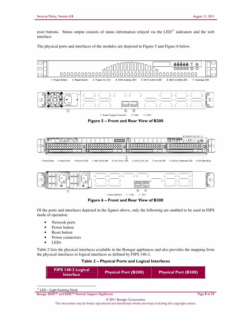
The physical ports and interfaces of the modules are depicted in Figure 5 and Figure 6 below.
Figure 5 – Front and Rear View of B200
Figure 6 – Front and Rear View of B300
Of the ports and interfaces depicted in the figures above, only the following are enabled to be used in FIPS
mode of operation:
• Network ports
• Power button
• Reset button
• Power connectors
• LEDs
Table 2 lists the physical interfaces available in the Bomgar appliances and also provides the mapping from
the physical interfaces to logical interfaces as defined by FIPS 140-2.
Table 2 – Physical Ports and Logical Interfaces
FIPS 140-2 Logical Interface
Physical Port (B200) Physical Port (B300)
11 LED – Light Emitting Diode
Security Policy, Version 0.8 August 11, 2011
Bomgar B200™ and B300™ Remote Support Appliances Page 10 of 29
© 2011 Bomgar Corporation This document may be freely reproduced and distributed whole and intact including this copyright notice.
FIPS 140-2 Logical Interface
Physical Port (B200) Physical Port (B300)
Data Input Network ports Network ports
Data Output Network ports Network ports
Control Input Network ports, power button, reset switch
Network ports, power button, reset switch
Status Output LEDs, network ports LEDs, network ports
Power Input Power connector Power connectors
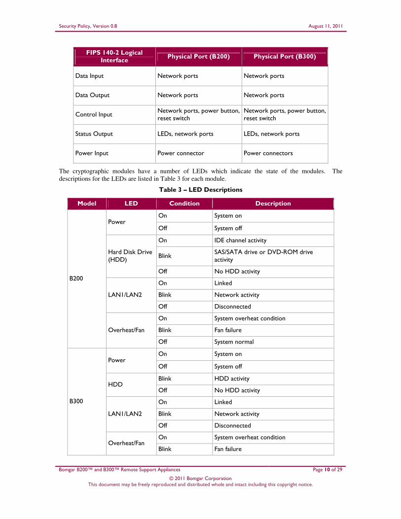
The cryptographic modules have a number of LEDs which indicate the state of the modules. The
descriptions for the LEDs are listed in Table 3 for each module.
Table 3 – LED Descriptions
Model LED Condition Description
B200
Power On System on
Off System off
Hard Disk Drive (HDD)
On IDE channel activity
Blink SAS/SATA drive or DVD-ROM drive activity
Off No HDD activity
LAN1/LAN2
On Linked
Blink Network activity
Off Disconnected
Overheat/Fan
On System overheat condition
Blink Fan failure
Off System normal
B300
Power On System on
Off System off
HDD Blink HDD activity
Off No HDD activity
LAN1/LAN2
On Linked
Blink Network activity
Off Disconnected
Overheat/Fan On System overheat condition
Blink Fan failure
Security Policy, Version 0.8 August 11, 2011
Bomgar B200™ and B300™ Remote Support Appliances Page 11 of 29
© 2011 Bomgar Corporation This document may be freely reproduced and distributed whole and intact including this copyright notice.
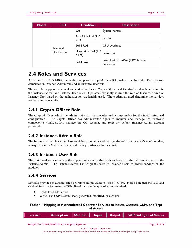
Model LED Condition Description
Off System normal
Universal Information
Fast Blink Red (1x/ sec)
Fan fail
Solid Red CPU overheat
Slow Blink Red (1x/ 4 sec)
Power fail
Solid Blue Local Unit Identifier (UID) button depressed
2.4 Roles and Services As required by FIPS 140-2, the module supports a Crypto-Officer (CO) role and a User role. The User role
comprises an Instance-Admin role and an Instance-User role.
The modules support role-based authentication for the Crypto-Officer and identity-based authentication for
the Instance-Admin and Instance-User roles. Operators explicitly assume the role of Instance-Admin or
Instance-User based on the authentication credentials used. The credentials used determine the services
available to the operator.
2.4.1 Crypto-Officer Role The Crypto-Officer role is the administrator for the modules and is responsible for the initial setup and
configuration. The Crypto-Officer has administrator rights to monitor and manage the firmware
component’s configuration, manage the CO account, and reset the default Instance-Admin account
passwords.
2.4.2 Instance-Admin Role The Instance-Admin has administrator rights to monitor and manage the software instance’s configuration,
manage Instance-Admin accounts, and manage Instance-User accounts.
2.4.3 Instance-User Role The Instance-User can access the support services in the modules based on the permissions set by the
Instance-Admin. The Instance-Admin has to grant access to Instance-Users to access services on the
modules.
2.4.4 Services
Services provided to authenticated operators are provided in Table 4 below. Please note that the keys and
Critical Security Parameters (CSPs) listed indicate the type of access required:
• Read: The CSP is read
• Write: The CSP is established, generated, modified, or zeroized
Table 4 – Mapping of Authenticated Operator Services to Inputs, Outputs, CSPs, and Type of Access
Service Description Operator Input Output CSP and Type of Access

Security Policy, Version 0.8 August 11, 2011
Bomgar B200™ and B300™ Remote Support Appliances Page 12 of 29
© 2011 Bomgar Corporation This document may be freely reproduced and distributed whole and intact including this copyright notice.
Service Description Operator Input Output CSP and Type of Access
Manage Bomgar appliance settings
Configure IP12 and TLS settings
CO Command Command response
RSA public key – Read, Write RSA private key – Read, Write Session Key – Read, Write PRNG13 seed – Read, Write CO Password – Read
Manage CO account
Manage CO officer account password
CO Command Command response
RSA public key – Read RSA private key – Read Session Key – Read, Write PRNG seed – Read, Write CO Password – Read, Write
Reset Instance-Admin password
Reset Instance-Admin account password
CO Command Command response
RSA public key – Read RSA private key – Read Session Key – Read, Write PRNG seed – Read, Write Instance-Admin Password – Write
Configure Instance-Admin accounts
Set up and monitor Instance- Admin accounts
CO, Instance-Admin
Command Command response
RSA public key – Read RSA private key – Read Session Key – Read, Write PRNG seed – Read, Write Instance-Admin Password – Read, Write
Configure Instance-User accounts
Set up and monitor Instance-User accounts
Instance-Admin, Instance-User
Command Command response
RSA public key – Read RSA private key – Read Session Key – Read, Write PRNG seed – Read, Write Instance-User Password – Read, Write
Execute self-tests
Perform power-up self-tests on demand
CO Command Command response
None
Monitor status Monitor the status of the modules
CO Command Status information
RSA public key – Read RSA private key – Read
Zeroize keys Zeroize plaintext keys
CO Command Command response
All CSPs – Write
Perform Representative Console service
Access and perform services for Representative Consoles
Instance-Admin, Instance-User
Command Command response
RSA public key – Read RSA private key – Read Session Key – Read, Write PRNG seed – Read, Write Instance-Admin Password – Read Instance-User Password – Read
Manage instance settings
Manage instance configuration settings
Instance-Admin, Instance-User
Command Command response
RSA public key – Read RSA private key – Read Session Key – Read, Write PRNG seed – Read, Write
12 IP – Internet Protocol 13 PRNG – Pseudo Random Number Generator

Security Policy, Version 0.8 August 11, 2011
Bomgar B200™ and B300™ Remote Support Appliances Page 13 of 29
© 2011 Bomgar Corporation This document may be freely reproduced and distributed whole and intact including this copyright notice.
2.4.5 Unauthenticated Operator Services The modules provide a service to unauthenticated operators as listed in Table 5 below.
Table 5 – Unauthenticated Operator Service
Service Description Input Output CSP and Type
of Access
Receive support service
Receive support services Command Command response
None
2.4.6 Authentication Mechanism The Crypto-Officer can access the modules remotely over a TLS session. The Crypto-Officer authenticates
to the modules using a user ID and password. Instance-Admins and Instance-Users authenticate themselves
with a user ID and password combination. Instance-Admins and Instance-Users can also authenticate to
the modules via one of the following configurable methods: LDAP, Kerberos, or RADIUS.
Table 6 lists the authentication mechanisms used by the modules.
Table 6 – Authentication Mechanism Used by the Modules
Authentication Type Strength
Password Passwords are required to be at least 6 characters in length and can be a maximum of 64 characters in length. Numeric, alphabetic (upper and lower cases), and keyboard/extended characters can be used, for a total of 95 characters to choose from. A six-character password will yield a total of 956 = 735,091,890,625 possible combinations.
2.5 Physical Security The B200™ and B300™ Remote Support Appliances are multi-chip standalone cryptographic modules.
Each is enclosed in a hard and opaque metal case that completely encloses all of the internal components of
the module. Tamper-evident labels are applied to the cases to provide physical evidence of attempts to gain
access to the modules’ internal components. All of the modules’ components are production grade. The
placement of tamper-evident labels can be found in Section 3.1 of this document.
2.6 Operational Environment The operational environment requirements do not apply to the Bomgar appliances. The modules provide
only a limited operational environment; they do not provide a general-purpose operating system
environment.
2.7 Cryptographic Key Management The modules implement the FIPS-Approved algorithms listed in Table 7.

Security Policy, Version 0.8 August 11, 2011
Bomgar B200™ and B300™ Remote Support Appliances Page 14 of 29
© 2011 Bomgar Corporation This document may be freely reproduced and distributed whole and intact including this copyright notice.
Table 7 – FIPS-Approved Algorithm Implementations
Algorithm B200 Certificate
Number B300 Certificate
Number
Advanced Encryption Standard (AES) in CBC14, ECB15, OFB16, and CFB17128 modes (with 128-bit, 192-bit, and 256-bit keys)
1563 1563
Triple Data Encryption Standard (TDES) – CBC, ECB, OFB, CFB8, and CFB64 modes (with 2- and 3-key)
1027 1027
RSA18 ANSI19 X9.31 (key generation) – 1024-, 1536-, 2048-bit
762 762
RSA Public Key Cryptography Standard #1 (PKCS#1) v1.5 (sign/verify) – 1024-, 2048-, 3072-, and 4096-bit
762 762
RSA Probabilistic Signature Scheme (PSS) (sign/verify) – 1024-, 2048-, 3072-, and 4096-bit
762 762
Secure Hash Algorithm (SHA)-1, SHA-224, SHA-256, SHA-384, and SHA-512
1388 1388
Keyed-Hash Message Authentication Code (HMAC) using SHA-1, SHA-224, SHA-256, SHA-384, and SHA-512
915 915
ANSI X9.31 A.2.4 PRNG 844 844
The modules also support the following non-FIPS-Approved algorithms:
• RSA key transport: 1024-, 1536-, 2048-, 3072-, 4096-bits (key wrapping; key establishment
methodology provides between 80 and 150 bits of encryption strength)
• RC420
• RC4-40
• DES
• DES-40
• MD521
The modules support the critical security parameters (CSPs) in Table 8.
14 CBC – Cipher Block Chaining 15 ECB – Electronic Codebook 16 OFB – Output Feedback 17 CFB – Cipher Feedback 18 RSA – Rivest, Shamir, and Adleman 19 ANSI – American National Standards Institute 20 RC – Rivest Cipher 4 21 MD – Message Digest 5
Security Policy, Version 0.8 August 11, 2011
Bomgar B200™ and B300™ Remote Support Appliances Page 15 of 29
© 2011 Bomgar Corporation This document may be freely reproduced and distributed whole and intact including this copyright notice.
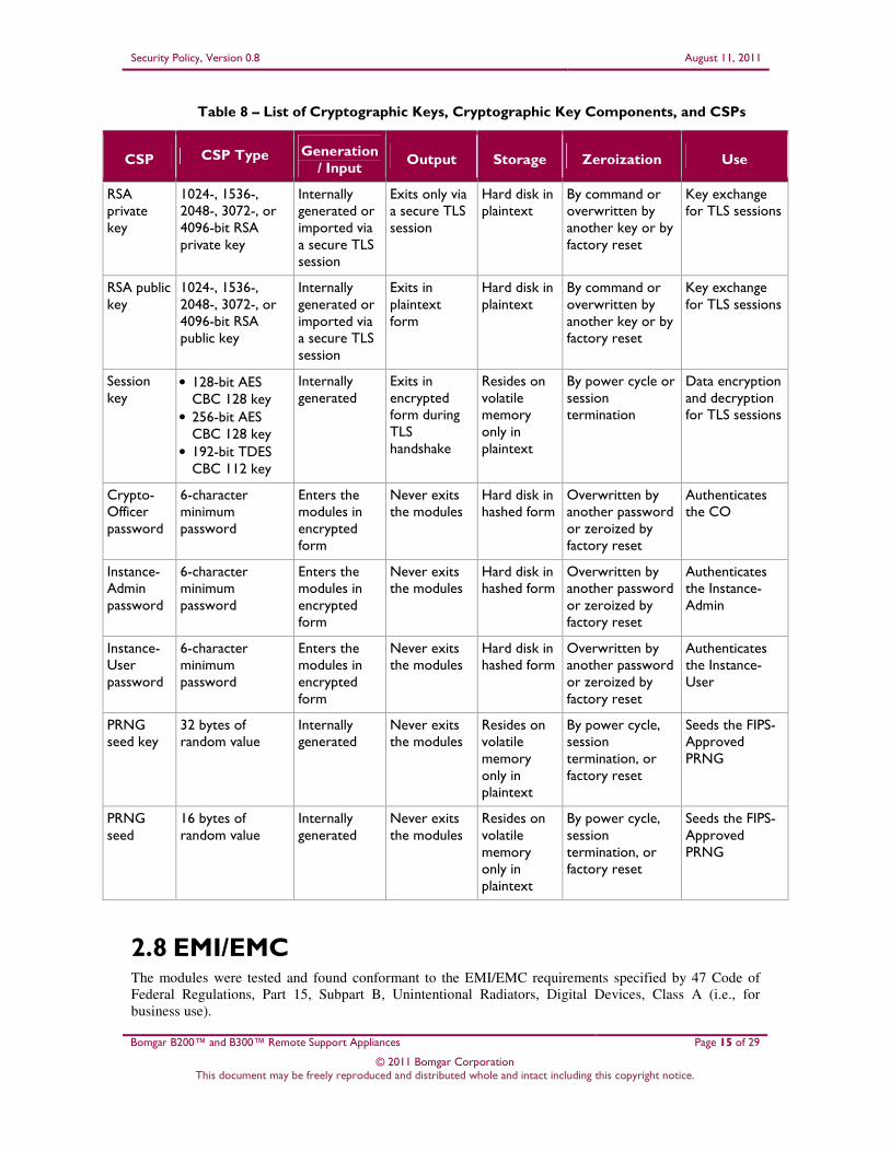
Table 8 – List of Cryptographic Keys, Cryptographic Key Components, and CSPs
CSP CSP Type Generation / Input
Output Storage Zeroization Use
RSA private key
1024-, 1536-, 2048-, 3072-, or 4096-bit RSA private key
Internally generated or imported via a secure TLS session
Exits only via a secure TLS session
Hard disk in plaintext
By command or overwritten by another key or by factory reset
Key exchange for TLS sessions
RSA public key
1024-, 1536-, 2048-, 3072-, or 4096-bit RSA public key
Internally generated or imported via a secure TLS session
Exits in plaintext form
Hard disk in plaintext
By command or overwritten by another key or by factory reset
Key exchange for TLS sessions
Session key
• 128-bit AES CBC 128 key
• 256-bit AES CBC 128 key
• 192-bit TDES CBC 112 key
Internally generated
Exits in encrypted form during TLS handshake
Resides on volatile memory only in plaintext
By power cycle or session termination
Data encryption and decryption for TLS sessions
Crypto-Officer password
6-character minimum password
Enters the modules in encrypted form
Never exits the modules
Hard disk in hashed form
Overwritten by another password or zeroized by factory reset
Authenticates the CO
Instance-Admin password
6-character minimum password
Enters the modules in encrypted form
Never exits the modules
Hard disk in hashed form
Overwritten by another password or zeroized by factory reset
Authenticates the Instance-Admin
Instance-User password
6-character minimum password
Enters the modules in encrypted form
Never exits the modules
Hard disk in hashed form
Overwritten by another password or zeroized by factory reset
Authenticates the Instance-User
PRNG seed key
32 bytes of random value
Internally generated
Never exits the modules
Resides on volatile memory only in plaintext
By power cycle, session termination, or factory reset
Seeds the FIPS-Approved PRNG
PRNG seed
16 bytes of random value
Internally generated
Never exits the modules
Resides on volatile memory only in plaintext
By power cycle, session termination, or factory reset
Seeds the FIPS-Approved PRNG
2.8 EMI/EMC The modules were tested and found conformant to the EMI/EMC requirements specified by 47 Code of
Federal Regulations, Part 15, Subpart B, Unintentional Radiators, Digital Devices, Class A (i.e., for
business use).

Security Policy, Version 0.8 August 11, 2011
Bomgar B200™ and B300™ Remote Support Appliances Page 16 of 29
© 2011 Bomgar Corporation This document may be freely reproduced and distributed whole and intact including this copyright notice.
2.9 Self-Tests
2.9.1 Power-Up Self-Tests
The Bomgar appliances perform the following self-tests at power-up to verify the integrity of the
software/firmware and the correct operation of the FIPS-Approved algorithm implementations employed
by the modules:
• Software/Firmware integrity check using a SHA-1 EDC22
• AES Known Answer Test (KAT)
• TDES KAT
• RSA KATs (sign/verify and encrypt/decrypt)
• HMAC KATs (SHA-1, SHA-224, SHA-256, SHA-384, and SHA-512)
• SHA-1 KAT (note that all SHA-2 implementations are tested as part of the underlying mechanism
of the HMAC SHA self-tests)
• ANSI X9.31 PRNG KAT
If any of the power-up self-tests fail, then the module enters an error state, logs the error to a file, and
disables all cryptographic operations.
2.9.2 Conditional Self-Tests
The Bomgar appliances perform the following conditional self-tests:
• ANSI X9.31 A.2.4 PRNG Continuous RNG test: Verifying the correct operation of the PRNG
algorithm implementation.
• RSA pair-wise consistency check (sign/verify and encrypt/decrypt): Verifying that a newly
generated RSA key pair works properly.
• Software/Firmware load test: Verifying the upgrade packages. Upgrade packages are digitally-
signed using RSA-4096, and are only loaded once the digital signature is verified.
If any of the conditional self-tests fail, then the modules enter a soft error state until the error can be
cleared.
2.10 Mitigation of Other Attacks
This section is not applicable. The modules do not claim to mitigate any attacks beyond the FIPS 140-2
Level 2 requirements for this validation.
22 EDC – Error Detection Code

Security Policy, Version 0.8 August 11, 2011
Bomgar B200™ and B300™ Remote Support Appliances Page 17 of 29
© 2011 Bomgar Corporation This document may be freely reproduced and distributed whole and intact including this copyright notice.
3 Secure Operation
The B200™ and B300™ Remote Support Appliances meet Level 2 requirements for FIPS 140-2. The
sections below describe how to ensure that the modules are running securely.
3.1 Initial Setup The following sections provide the necessary step-by-step instructions for the secure hardware installation
of the B200™ and B300™ Remote Support Appliances, as well as the steps necessary to configure the
modules for FIPS-Approved mode of operation. If you have any questions or if issues arise at any point
during the installation and configuration of your Bomgar appliances, contact the Bomgar support team toll-
free at 1-877-826-6427 x2 or internationally at +01-601-519-0123 x2.
3.1.1 B200 Hardware Setup In order to set up the Bomgar B200, the following steps will need to be performed by the Crypto-Officer:
1. Inspect the tamper-evident labels as described in Section 3.1.2 below. The tamper evident labels
shall be installed for the module to operate in a FIPS Approved mode of operation.
2. Follow the procedures included in the Hardware Setup Guide to install your B200 in your server
rack.
3. After you have installed the Bomgar B200 per the Hardware Setup Guide, refer to the included
Getting Started Guide and configure your network settings.
4. Once the Bomgar B200’s network settings are correctly configured, return to Section 3.1.4.1 in
this document to configure your B200 for FIPS mode.
3.1.2 B200 Label Inspection The B200 will be shipped from the factory with all required labels pre-applied. Upon delivery, an
authorized individual should ensure that the module was not tampered with during shipment and that the
labels have been applied properly. . Also, tamper-evident labels shall be routinely inspected for damage by
the Crypto-Officer, and replaced accordingly.
Inspect all tamper-evident labels that shipped pre-applied to the B200 chassis (see Figure 7 and Figure 8),
ensuring that each label shows no sign of tampering and is properly placed. Any attempt to reposition or
remove the label will result in the voiding of that label and leave a residue on the surface. If you find a
label that is questionable in appearance, contact Bomgar support toll-free at 1-877-826-6427 x2 or
internationally at +01-601-519-0123 x2.

Security Policy, Version 0.8 August 11, 2011
Bomgar B200™ and B300™ Remote Support Appliances Page 18 of 29
© 2011 Bomgar Corporation This document may be freely reproduced and distributed whole and intact including this copyright notice.
Figure 7 – Tamper seal applied to the top, overlapping the galvanized metal cover and the front panel
Figure 8 – Tamper seal applied to the rear, overlapping the galvanized metal cover and rear steel bezel
3.1.3 B300 Hardware Setup In order to set up the Bomgar B300, the following steps will need to be performed by an authorized
individual:
1. Unpack the Bomgar B300 and remove the front bezel from the front of the B300:
a. Loosen the set screw on the right side of the front bezel. This screw keeps the tab in
place during shipping.
b. Press the tab on the right side of the front bezel and pull the front bezel towards you, right
side first.
Pre-Applied
Tamper Evident
Label 1
Pre-Applied
Tamper Evident
Label 2

Security Policy, Version 0.8 August 11, 2011
Bomgar B200™ and B300™ Remote Support Appliances Page 19 of 29
© 2011 Bomgar Corporation This document may be freely reproduced and distributed whole and intact including this copyright notice.
2. Reseat the hard drives:
a. Remove each of the hard drives by pressing the dark red buttons to unlatch the drive
carrier handles. Use the handles to pull the drives about halfway out of the Bomgar
chassis.
b. As you reinsert each of the drives, the carrier handles will begin to close. Close the
handles (you will feel them lock) and fully insert the drives into the B300 by firmly
pressing on the left and right edges of the front of the drive carriers. Even if no
movement is felt, this helps to ensure that the disk is completely engaged.
3. Reattach the B300’s front bezel:
a. Engage the left side of the faceplate first, taking care to align the stubs of the faceplate
with the drilled holes in the left ear.
b. Repeat on the right side and then tighten the set screw. Take care not to over tighten this
screw.
4. Inspect the tamper-evident labels as described in Section 3.1.4 below. The tamper evident labels
shall be installed for the module to operate in a FIPS Approved mode of operation. If you find a
label that is questionable in appearance, contact Bomgar support at 1-877-8-BOMGAR x2 or
internationally at +01-601-519-0123 x2.
5. Follow the procedures included in the Hardware Setup Guide to install your B300 in your server
rack.
6. After you have installed the Bomgar B300 per the Hardware Setup Guide, refer to the included
Getting Started Guide and configure your network settings.
7. Once the Bomgar B300’s network settings are correctly configured, return to Section 3.1.4.1 in
this document to configure your B300 for FIPS mode.
3.1.4 B300 Label Inspection and Application The B300 will be shipped from the factory with all required labels pre-applied except for the front bezel
labels. This is to allow the end-user to reseat the drives upon receipt before affixing the front bezel to the
appliance. Upon delivery, the Crypto-Officer should ensure that the module was not tampered with during
shipment and that the labels have been applied properly. . Also, tamper-evident labels shall be routinely
inspected for damage by the Crypto-Officer, and replaced accordingly.
1. Inspect all tamper-evident labels that shipped pre-applied to the Bomgar B300 chassis (see Figure
9), ensuring that each label shows no sign of tampering and is properly placed. Any attempt to
reposition or remove the label will result in the voiding of that label and leave a residue on the
surface. If you find a label that is questionable in appearance, contact Bomgar support toll-free at
1-877-826-6427 x2 or internationally at +01-601-519-0123 x2.
2. To apply the front bezel labels, first you must clean the top surface and front bezel of the B300
with isopropyl alcohol in the area where the tamper-evident labels will be placed.
3. Holding label by edges, place label on surface as indicated in the figures below.
4. Apply the included tamper-evident labels by rubbing gently across entire label to ensure adhesion
to the surface.
NOTE: Any attempt to reposition or remove the label will result in the voiding of that label and
leave a residue on the surface.
5. Allow the labels to fully adhere to the B300 within 24 hours in a physically secure environment
before placing it in the intended environment.

Security Policy, Version 0.8 August 11, 2011
Bomgar B200™ and B300™ Remote Support Appliances Page 20 of 29
© 2011 Bomgar Corporation This document may be freely reproduced and distributed whole and intact including this copyright notice.
Figure 9 – Rear metallic bezel seal (Left) and Sealed top cover (Right)
Figure 10 – Sealed front bezel to chassis top (Left) and Sealed front bezel to chassis bottom (Right)
Figure 11– Sealed top chassis to left power supply (Left) and Sealed top chassis to right power supply (Right)
Pre-Applied
Tamper
Evident
Label 1
Pre-Applied
Tamper
Evident
Label 2
Tamper
Evident
Label 3
Tamper
Evident
Label 4
Tamper
Evident
Label 5
Tamper
Evident
Label 6

Security Policy, Version 0.8 August 11, 2011
Bomgar B200™ and B300™ Remote Support Appliances Page 21 of 29
© 2011 Bomgar Corporation This document may be freely reproduced and distributed whole and intact including this copyright notice.
3.1.4.1 B200 and B300 FIPS Mode Configuration
Once all necessary initialization procedures have been performed as described in the preceding sections, the
modules need to be configured to comply with FIPS 140-2 requirements. Once configured as described in
this section, the modules will be considered to be in FIPS-Approved mode, which can be verified at any
time by viewing the SSL Configuration page and ensuring it matches Figure 13 (NOTE: Figure 13 is
identical for both the B200 and B300 with the exception of the heading).
FIPS-Approved Mode Configuration
Log into the Bomgar Appliance Administrative Interface (e.g. support.example.com/appliance) and
configure your settings as described below23
:
1. Navigate to the IP Configuration page under the Networking tab (see Figure 12 below).
2. Click the default 169.254.1.1 IP address to edit it.
3. Set the Telnet Server setting to Simplified.
4. Click the Save Changes button to commit these configuration changes.
Figure 12 – IP Configuration Page
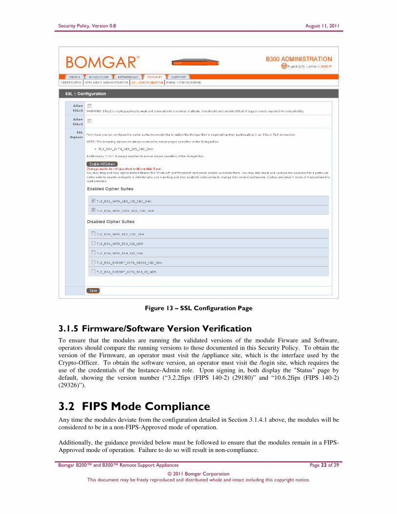
5. Navigate to the SSL Configuration page under the Security tab (see Figure 13 below).
6. Disable SSLv2 by ensuring that the Allow SSLv2 checkbox is cleared.
7. Disable SSLv3 by ensuring that the Allow SSLv3 checkbox is cleared
8. Ensure that only FIPS-Approved cipher suites are enabled:
a. TLS_RSA_WITH_AES_128_CBC_SHA
b. TLS_RSA_WITH_3DES_EDE_CBC_SHA
9. Click the Save button to commit these configuration changes.
23 NOTE: The module comes preloaded with a default password. The Crypto-Officer is responsible for changing this password before
proceeding with the configuration steps.
Security Policy, Version 0.8 August 11, 2011
Bomgar B200™ and B300™ Remote Support Appliances Page 22 of 29
© 2011 Bomgar Corporation This document may be freely reproduced and distributed whole and intact including this copyright notice.
Figure 13 – SSL Configuration Page
3.1.5 Firmware/Software Version Verification To ensure that the modules are running the validated versions of the module Firware and Software,
operators should compare the running versions to those documented in this Security Policy. To obtain the
version of the Firmware, an operator must visit the /appliance site, which is the interface used by the
Crypto-Officer. To obtain the software version, an operator must visit the /login site, which requires the
use of the credentials of the Instance-Admin role. Upon signing in, both display the "Status" page by
default, showing the version number (“3.2.2fips (FIPS 140-2) (29180)” and “10.6.2fips (FIPS 140-2)
(29326)”).
3.2 FIPS Mode Compliance Any time the modules deviate from the configuration detailed in Section 3.1.4.1 above, the modules will be
considered to be in a non-FIPS-Approved mode of operation.
Additionally, the guidance provided below must be followed to ensure that the modules remain in a FIPS-
Approved mode of operation. Failure to do so will result in non-compliance.

Security Policy, Version 0.8 August 11, 2011
Bomgar B200™ and B300™ Remote Support Appliances Page 23 of 29
© 2011 Bomgar Corporation This document may be freely reproduced and distributed whole and intact including this copyright notice.
• When entering OR leaving FIPS-Approved mode, navigate to the Basics page under the Status
tab of the /appliance interface and clear all existing CSPs by clicking the Reset Appliance to
Factory Defaults button.
NOTE: All Firmware and Software will be completely uninstalled after reset.
Figure 14 – Status Basics Page
• Never install software or firmware versions other than those listed on the cover page of this
security policy. Only the software and firmware versions listed, are considered part of the
validated configuration.
• When using the module’s administrative interface, do not use the Advanced Support page under
the Support tab of the /appliance interface. Doing so will result in non-compliance.

Security Policy, Version 0.8 August 11, 2011
Bomgar B200™ and B300™ Remote Support Appliances Page 24 of 29
© 2011 Bomgar Corporation This document may be freely reproduced and distributed whole and intact including this copyright notice.
Figure 15 – Advanced Support Page
• Enforce minimum password requirements for the Instance-Admin and Instance-User roles using
the Security page under the Management tab.
Figure 16 – Security Page
• When using the management interface, do not use the Support page under the Management tab
of the /login interface.

Security Policy, Version 0.8 August 11, 2011
Bomgar B200™ and B300™ Remote Support Appliances Page 25 of 29
© 2011 Bomgar Corporation This document may be freely reproduced and distributed whole and intact including this copyright notice.
Figure 17 – Support Page
• Never install a Bomgar software package via the Software Management page under the
Management tab of the /login interface. Instead, ensure that any received Bomgar software
packages are FIPS-Approved, and upload them from the Updates page under the Support tab of
the administrative interface (e.g. support.example.com/appliance). You should always upload
updates manually rather than using the auto-update feature. To maintain compliance, only the
software update versions listed in this security policy are to be used.
3.3 Crypto-Officer Guidance The Crypto-Officer can initiate the execution of self-tests and can access the modules’ status reporting
capability. Self-tests can be initiated at any time by power cycling the modules.
3.3.1 Management It is the responsibility of the Crypto-Officer to ensure that the modules are set up to run securely. Please
refer to Section 3.2 for guidance that the Crypto-Officer must follow for the modules to be considered in a
FIPS-Approved mode of operation. Additionally, the Crypto-Officers should be careful to protect any
secret/private keys in their possession.
For details regarding the management of the modules, please refer to the appropriate Bomgar appliance
Administrative User’s Guide.
3.3.2 Status Monitoring
Error message and status review is the responsibility of the Crypto-Officer. When any of the modules’
self-tests fail, the module reports an error message which can be viewed over a network connection. This
connection is set using the IP Configuration page under the Networking tab as shown in Figure 12 in
Section 3.1.4.1. Issuing the command "telnet [ip-address-assigned-to-network-port]" brings up the
following options:
1. Show Error Message
2. Shutdown the Device
3. Reboot the Device

Security Policy, Version 0.8 August 11, 2011
Bomgar B200™ and B300™ Remote Support Appliances Page 26 of 29
© 2011 Bomgar Corporation This document may be freely reproduced and distributed whole and intact including this copyright notice.
4. Reset the Device to Factory Default
5. Done
Issuing the Show Error Message command will display the reported error message.
3.3.3 Zeroization Session keys are zeroized at the termination of the session but are also cleared when the module is power-
cycled. All other CSPs may be zeroized by either:
• issuing the Reset Appliance to Factory Defaults command (found on the Basics page under the
Status tab) and rebooting the module, or
• selecting the Reset the Device to Factory Default option from a telnet session and rebooting the
module.
The zeroization of keys and CSPs is immediate, providing insufficient time for an attacker to compromise
them. The Crypto-Officer must wait until the module has successfully rebooted in order to verify that
zeroization has completed.
3.4 Instance-Admin and Instance-User Guidance The Instance-Admins do not have the ability to configure sensitive information on the modules, with the
exception of the Instance-User and their own passwords. The Instance-Admin has the ability to configure
the password strength policy for Instance-Admins and Instance-Users. Please refer to Section 3.2 above for
guidance that should be followed for the modules to be considered in a FIPS-Approved mode of operation.
Instance-Users do not have the ability to configure sensitive information on the modules, with the
exception of their passwords. The Instance-Admins and Instance-Users shall employ strong passwords that
meet or exceed the password strength requirements documented in Section 2.4.6 of this document, and
must not reveal their passwords to anyone.

Security Policy, Version 0.8 August 11, 2011
Bomgar B200™ and B300™ Remote Support Appliances Page 27 of 29
© 2011 Bomgar Corporation This document may be freely reproduced and distributed whole and intact including this copyright notice.
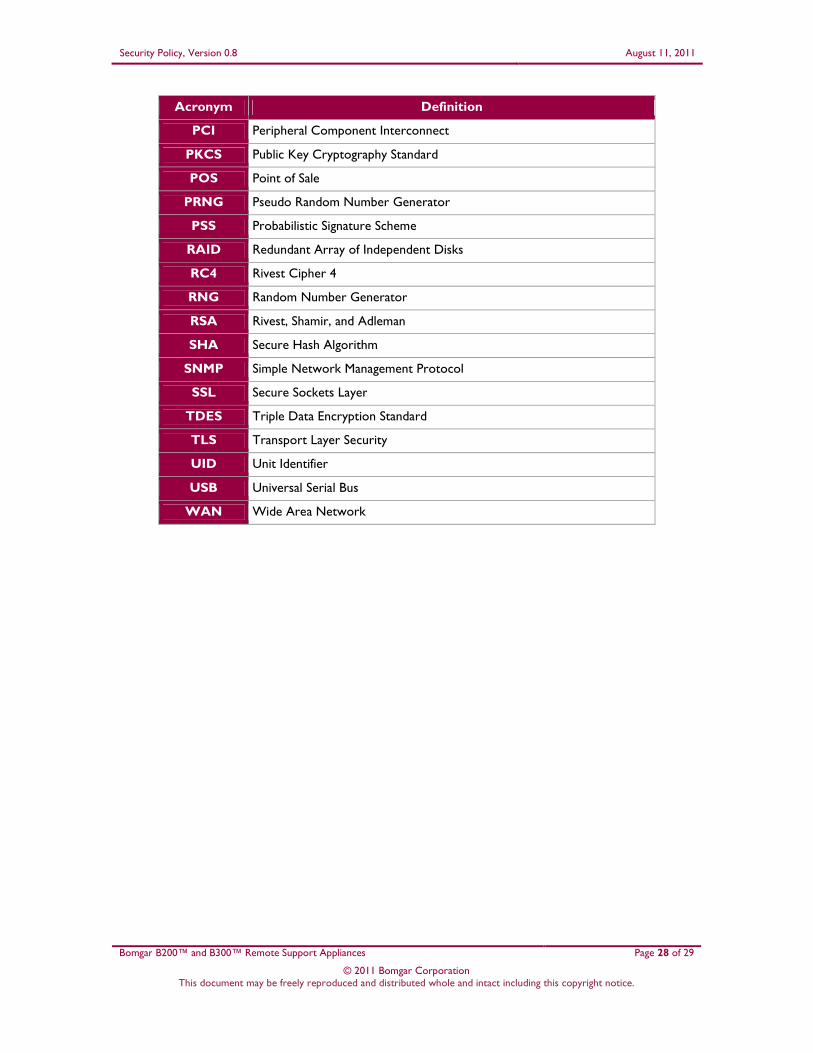
4 Acronyms This section describes the acronyms used in this document.
Table 9 – Acronyms
Acronym Definition
AD Active Directory
AES Advanced Encryption Standard
ANSI American National Standards Institute
API Application Programming Interface
CBC Cipher Block Chaining
CFB Cipher Feedback
CMVP Cryptographic Module Validation Program
CO Crypto-Officer
CSEC Communication Security Establishment Canada
CSP Critical Security Parameter
DMZ Demilitarized Zone
ECB Electronic Codebook
EDC Error Detection Code
EMC Electromagnetic Compatibility
EMI Electromagnetic Interference
FIPS Federal Information Processing Standard
HDD Hard Disk Drive
HMAC (Keyed-) Hash Message Authentication Code
HTTP Hypertext Transfer Protocol
HTTPS Hypertext Transfer Protocol over TLS
IP Internet Protocol
IPMI Intelligent Platform Management Interface
KAT Known Answer Test
LAN Local Area Network
LDAP Lightweight Directory Access Protocol
LED Light Emitting Diode
MD5 Message Digest 5
N/A Not Applicable
NIST National Institute of Standards and Technology
OFB Output Feedback
Security Policy, Version 0.8 August 11, 2011
Bomgar B200™ and B300™ Remote Support Appliances Page 28 of 29
© 2011 Bomgar Corporation This document may be freely reproduced and distributed whole and intact including this copyright notice.
Acronym Definition
PCI Peripheral Component Interconnect
PKCS Public Key Cryptography Standard
POS Point of Sale
PRNG Pseudo Random Number Generator
PSS Probabilistic Signature Scheme
RAID Redundant Array of Independent Disks
RC4 Rivest Cipher 4
RNG Random Number Generator
RSA Rivest, Shamir, and Adleman
SHA Secure Hash Algorithm
SNMP Simple Network Management Protocol
SSL Secure Sockets Layer
TDES Triple Data Encryption Standard
TLS Transport Layer Security
UID Unit Identifier
USB Universal Serial Bus
WAN Wide Area Network

Prepared by: Corsec Security, Inc.
13135 Lee Jackson Memorial Highway, Suite 220 Fairfax, VA 22033
United States of America
Phone: +1 (703) 267-6050 Email: [email protected] http://www.corsec.com