Embed Size (px)
Citation preview
Bomberman: Defining and DefeatingHardware Ticking Timebombs at Design-time
Timothy Trippel∗, Kang G. ShinComputer Science & Engineering
University of MichiganAnn Arbor, MI
{trippel,kgshin}@umich.edu
Kevin B. BushCyber-Physical SystemsMIT Lincoln Laboratory
Lexington, [email protected]
Matthew Hicks∗†Computer Science
Virginia TechBlacksburg, VA
Abstract—To cope with ever-increasing design complexities,integrated circuit designers increase both the size of their designteams and their reliance on third-party intellectual property (IP).Both come at the expense of trust: it is computationally infeasibleto exhaustively verify that a design is free of all possible maliciousmodifications (i.e., hardware Trojans). Making matters worse,unlike software, hardware modifications are permanent: there isno “patching” mechanism for hardware; and powerful: they serveas a foothold for subverting software that sits above.
To counter this threat, prior work uses both static and dynamicanalysis techniques to verify hardware designs are Trojan-free.Unfortunately, researchers continue to reveal weaknesses inthese “one-size-fits-all”, heuristic-based approaches. Instead ofattempting to detect all possible hardware Trojans, we takethe first step in addressing the hardware Trojan threat in adivide-and-conquer fashion: defining and eliminating TickingTimebomb Trojans (TTTs), forcing attackers to implement largerTrojan designs detectable via existing verification and side-channel defenses. Like many system-level software defenses (e.g.,Address Space Layout Randomization (ASLR) and Data Execu-tion Prevention (DEP)), our goal is to systematically constrict thehardware attacker’s design space.
First, we construct a definition of TTTs derived from theirfunctional behavior. Next, we translate this definition into fun-damental components required to realize TTT behavior inhardware. Using these components, we expand the set of allknown TTTs to a total of six variants—including unseen variants.Leveraging our definition, we design and implement a TTT-specific dynamic verification toolchain extension, called Bomber-man. Using four real-world hardware designs, we demonstrateBomberman’s ability to detect all TTT variants, where previousdefenses fail, with <1.2% false positives.
Index Terms—Hardware Trojans, Ticking Timebombs, 3rdParty IP, Verification
I. INTRODUCTION
As microelectronic hardware continues to scale, so toohave design complexities. To design an Integrated Circuit(IC) of modern complexity targeting a 7nm process requires500 engineering years [1], [2]. Because it is impractical totake 500 years to create a chip, semiconductor companiesreduce time-to-market by adding engineers: increasing boththe size of their design teams and their reliance on 3rd-partyIntellectual Property (IP). Namely, they purchase pre-designed
* Work completed at MIT Lincoln Laboratory.† Corresponding faculty author
Ticking Timebomb Trojan
Ticking Timebomb Trigger
Event
Increment
+0 1 0 1
Payload
0101
==
Activation
Signal
Comparator
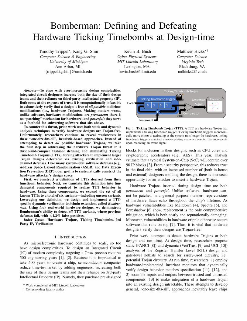
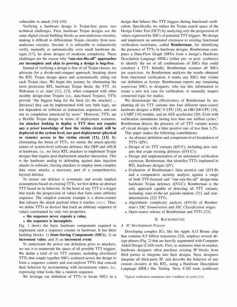
Fig. 1. Ticking Timebomb Trojan (TTT). A TTT is a hardware Trojan thatimplements a ticking timebomb trigger. Ticking timebomb triggers monotoni-cally move closer to activating as the system runs longer. In hardware, tickingtimebomb triggers maintain a non-repeating sequence counter that incrementsupon receiving an event signal.
blocks for inclusion in their designs, such as CPU cores andcryptographic accelerators (e.g., AES). This year, analystsestimate that a typical System-on-Chip (SoC) will contain over90 IP blocks [3]. From a security perspective, this reduces trustin the final chip: with an increased number of (both in-houseand external) designers molding the design, there is increasedopportunity for an attacker to insert a hardware Trojan.
Hardware Trojans inserted during design time are bothpermanent and powerful. Unlike software, hardware can-not be patched in a general-purpose manner; repercussionsof hardware flaws echo throughout the chip’s lifetime. Ashardware vulnerabilities like Meltdown [4], Spectre [5], andForeshadow [6] show, replacement is the only comprehensivemitigation, which is both costly and reputationally damaging.Moreover, vulnerabilities in hardware cripple otherwise securesoftware that runs on top [7]. Thus, it is vital that hardwaredesigners verify their designs are Trojan-free.
Prior work attempts to detect hardware Trojans at bothdesign and run time. At design time, researchers proposestatic (FANCI [8]) and dynamic (VeriTrust [9] and UCI [10])analyses of the Register Transfer Level (RTL) design andgate-level netlists to search for rarely-used circuitry, i.e.,potential Trojan circuitry. At run time, researchers: 1) employhardware-implemented invariant monitors that dynamicallyverify design behavior matches specification [11], [12], and2) scramble inputs and outputs between trusted and untrustedcomponents [13] to make integration of a hardware Trojaninto an existing design intractable. These attempts to developgeneral, “one-size-fits-all”, approaches inevitably leave chips
vulnerable to attack [14]–[16].Verifying a hardware design is Trojan-free poses two
technical challenges. First, hardware Trojan designs use thesame digital circuit building blocks as non-malicious circuitry,making it difficult to differentiate Trojan circuitry from non-malicious circuitry. Second, it is infeasible to exhaustivelyverify, manually or automatically, even small hardware de-signs [17], let alone designs of moderate complexity. Thesechallenges are the reason why “one-size-fits-all” approachesare incomplete and akin to proving a design is bug-free.
Instead of verifying a design is free of all Trojan classes, weadvocate for a divide-and-conquer approach, breaking downthe RTL Trojan design space and systematically ruling outeach Trojan class. We begin this journey by eliminating themost pernicious RTL hardware Trojan threat: the TTT. AsWaksman et al. state [11], [13], when compared with otherstealthy design-time Trojans (i.e., data-based Trojans), TTTsprovide “the biggest bang for the buck [to the attacker] ...[because] they can be implemented with very little logic, arenot dependent on software or instruction sequences, and canrun to completion unnoticed by users.” Moreover, TTTs area flexible Trojan design in terms of deployment scenarios.An attacker looking to deploy a TTT does not requireany a priori knowledge of how the victim circuit will bedeployed at the system level, nor post-deployment (physicalor remote) access to the victim circuit [11], [13]. Byeliminating the threat of TTTs, we mimic the attack-specificnature of system-level software defenses like DEP and ASLRin hardware, i.e., we force RTL attackers to implement Trojandesigns that require post-deployment attacker interaction. Thisis the hardware analog to defending against data injectionattacks in software, forcing attackers to employ more complexdata reuse attacks; a necessary part of a comprehensive,layered defense.
To ensure our defense is systematic and avoids implicitassumptions based on existing TTTs, we first define an abstractTTT based on its behavior. At the heart of any TTT is a triggerthat tracks the progression of values that form some arbitrarysequence. The simplest concrete example is a down-counterthat releases the attack payload when it reaches zero. Thus,we define TTTs as devices that track an arbitrary sequence ofvalues constrained by only two properties:
• the sequence never repeats a value,• the sequence is incomplete.
Fig. 1 shows the basic hardware components required toimplement such a sequence counter in hardware. It has threebuilding blocks: 1) State-Saving Components (SSCs), 2) anincrement value, and 3) an increment event.
To understand the power our definition gives to attackers,we use it to enumerate the space of all possible TTT triggers.We define a total of six TTT variants, including distributedTTTs that couple together SSCs scattered across the design toform a sequence counter and non-uniform TTTs that concealtheir behavior by incrementing with inconsistent values, i.e.,expressing what looks like a random sequence.
We leverage our definition of TTTs to locate SSCs in a
design that behave like TTT triggers during functional verifi-cation. Specifically, we reduce the Trojan search space of theDesign Under Test (DUT) by analyzing only the progression ofvalues expressed by SSCs of potential TTT triggers. We designand implement an automated extension to existing functionalverification toolchains, called Bomberman, for identifyingthe presence of TTTs in hardware designs. Bomberman com-putes a Data-Flow Graph (DFG) from a design’s HardwareDescription Language (HDL) (either pre- or post- synthesis)to identify the set of all combinations of SSCs that couldconstruct a TTT. Initially, Bomberman assumes all SSCsare suspicious. As Bomberman analyzes the results obtainedfrom functional verification, it marks any SSCs that violateour definition as benign. Bomberman reports any remainingsuspicious SSCs to designers, who use this information tocreate a new test case for verification, or manually inspectconnected logic for malice.
We demonstrate the effectiveness of Bomberman by im-planting all six TTT variants into four different open-sourcehardware designs: a RISC-V CPU [18], an OR1200 CPU [19],a UART [19] module, and an AES accelerator [20]. Even withverification simulations lasting less than one million cycles,1
Bomberman detects the presence of all TTT variants acrossall circuit designs with a false positive rate of less than 1.2%.
This paper makes the following contributions:• An abstract definition and component-level breakdown of
TTTs (§IV).• Design of six TTT variants (§IV-C), including new vari-
ants that evade existing defenses (§VI-C1).• Design and implementation of an automated verification
extension, Bomberman, that identifies TTTs implanted inRTL hardware designs (§V).
• Evaluation of Bomberman’s false positive rate (§VI-B)and a comparative security analysis against a rangeof both TTT-focused and “one-size-fits-all” design-timehardware Trojan defenses (§VI-C); Bomberman is theonly approach capable of detecting all TTT variants,including state-of-the-art pseudo-random [21] and non-deterministic [22] TTTs.
• Algorithmic complexity analysis (§VI-D) of Bomber-man’s SSC Enumeration and SSC Classification stages.
• Open-source release of Bomberman and TTTs [23].
II. BACKGROUND
A. IC Development Process
Developing complex ICs, like the Apple A13 Bionic chipthat contains 8.5 billion transistors [24], employs several de-sign phases (Fig. 2) that are heavily augmented with ComputerAided Design (CAD) tools. First, to minimize time-to-market,hardware designers often purchase existing IP blocks fromthird parties to integrate into their designs. Next, designersintegrate all third-party IP, and describe the behavior of anycustom circuitry at the RTL, using a Hardware DescriptionLanguage (HDL) like Verilog. Next, CAD tools synthesize
1Typical verification simulations last ≈millions of cycles [11].
3rd Party IP RTL Design Synthesis Physical Layout Fabrication Packaging/
Deployment
Front-End Design = Design-Time Attack Points
Verif
icat
ion
Verif
icat
ion
Verif
icat
ion
Fig. 2. IC Development Process. As ICs have become increasingly complex, both the reuse of 3rd party IP and the size of design teams has increased [3].
the HDL into a gate-level netlist (also described using HDL)targeting a specific process technology, a process analogousto software compilation. After synthesis, designers lay out thecircuit components (i.e., logic gates) on a 3-dimensional gridand route wires between them to connect the entire circuit.CAD tools encode the physical layout in a Graphics DatabaseSystem II (GDSII) format, which is then sent to the fabricationfacility. Finally, the foundry fabricates the IC, and returns itto the designers who test and package it for mounting ontoa printed circuit board. HDL-level Trojans inserted at designtime compromise the final chip—even if the tools, back-enddesign, and fabrication are secure.
B. Hardware Trojans
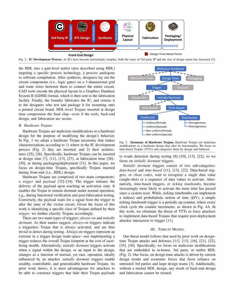
Hardware Trojans are malicious modifications to a hardwaredesign for the purpose of modifying the design’s behavior.In Fig. 3 we adopt a hardware Trojan taxonomy that makescharacterizations according to 1) where in the IC developmentprocess (Fig. 2) they are inserted, and 2) their architec-tures [25], [26]. Specifically, hardware Trojans can be insertedat design time [7], [11], [13], [27], at fabrication time [28]–[30], or during packaging/deployment [31]. In this paper, wefocus on design-time Trojans, specifically Trojans insertedduring front-end (i.e., HDL) design.
Hardware Trojans are comprised of two main components:a trigger and payload [32]–[34]. The trigger initiates thedelivery of the payload upon reaching an activation state. Itenables the Trojan to remain dormant under normal operation,e.g., during functional verification and post-fabrication testing.Conversely, the payload waits for a signal from the trigger toalter the state of the victim circuit. Given the focus of thiswork is identifying a specific class of Trojans defined by theirtrigger, we further classify Trojans accordingly.
There are two main types of triggers: always-on and initiallydormant. As their names suggest, always-on triggers indicatea triggerless Trojan that is always activated, and are thustrivial to detect during testing. Always-on triggers represent anextreme in a trigger design trade-space—not implementing atrigger reduces the overall Trojan footprint at the cost of sacri-ficing stealth. Alternatively, initially dormant triggers activatewhen a signal within the design, or an input to the design,changes as a function of normal, yet rare, operation, ideallyinfluenced by an attacker. initially dormant triggers enablestealthy, controllable, and generalizable hardware Trojans. Asprior work shows, it is most advantageous for attackers tobe able to construct triggers that hide their Trojan payloads
Malicious Hardware
Design TimeFabrication Time Packaging
Trigger Payload
Always On Initially Dormant
Data-Based Time-Based
DistributedCoalescedHomogeneousHeterogeneous
Uniform/PeriodicUniform/Sporadic
Non-uniform/SporadicNon-uniform/Periodic
Fig. 3. Taxonomy of Hardware Trojans. Hardware Trojans are maliciousmodifications to a hardware design that alter its functionality. We focus ontime-based Trojans (TTTs) and categorize them by design and behavior.
to evade detection during testing [8]–[10], [13], [22], so wefocus on initially dormant triggers.
Initially dormant triggers consist of two sub-categories:data-based and time-based [11], [13], [22]. Data-based trig-gers, or cheat codes, wait to recognize a single data value(single-shot) or a sequence of data values to activate. Alter-natively, time-based triggers, or ticking timebombs, becomeincreasingly more likely to activate the more time has passedsince a system reset. While, ticking timebombs can implementa indirect and probabalistic notion of time (§IV), a simpleticking timebomb trigger is a periodic up-counter, where everyclock cycle the counter increments, as shown in Fig. 4A. Inthis work, we eliminate the threat of TTTs to force attackersto implement data-based Trojans that require post-deploymentattacker interaction to trigger [11].
III. THREAT MODEL
Our threat model follows that used by prior work on design-time Trojan attacks and defenses [11], [13], [16], [21], [22],[35], [36]. Specifically, we focus on malicious modificationsthat are embedded in in-house, 3rd party, or netlist HDL(Fig. 2). Our focus, on design-time attacks is driven by currentdesign trends and economic forces that favor reliance onuntrusted 3rd parties and large design teams [3]. Additionally,without a trusted HDL design, any result of back-end designand fabrication cannot be trusted.
We assume that a design-time adversary has the ability toadd, remove, and modify the RTL or netlist HDL of the coredesign in order to implement hardware Trojans. This can bedone either by a single rogue employee at a hardware designcompany, or by entirely rogue design teams. We also assumean attacker only makes modifications that evade detectionduring design verification. Thus, no part of the design canbe trusted until vetted by Bomberman and other heuristics-based tools [8]–[10]. Like prior work [8]–[10], [13], [21], [22],we assume that malicious circuit behavior triggered by Trojanactivation is caught via verification testing.
We focus on identifying TTTs as we define them in §IV.In doing so, we force attackers to implement data-based(cheat code) Trojans, which require large state machines toachieve stealth during design verification [14], [15], sub-sequently making them detectable post-fabrication via sidechannels [37]–[43]. Moreover, data-based Trojans have limiteddeployability—e.g., they cannot target air-gapped machines—since they require post-deployment attacker interaction [11].Our defense can be deployed at any point throughout thefront-end design process—i.e., directly verifying 3rd party IP,after RTL design, or after synthesis—after which the designis trusted to be free of TTTs.
IV. TICKING TIMEBOMB TRIGGERS
First, we define TTTs by their behavior. Based on thisdefinition, we synthesize the fundamental components requiredto implement a TTT in hardware. Finally, using these fun-damental components we enumerate six total TTT variants,including previously contrived TTTs that resemble contiguoustime counters [11], [13], to more complex, distributed, non-uniform, and sporadic [21], [22] designs.
A. Definition
We define TTTs as the set of hardware Trojans that im-plement a time-based trigger that monotonically approachesactivation as the victim circuit continuously operates withoutreset. More succinctly, we define a ticking timebomb triggerbased on two properties of the values it exhibits while stilldormant yet monotonically approaching activation:Property 1: The TTT does NOT repeat a value without a
system reset.Property 2: The TTT does NOT enumerate all possible val-
ues without activating.Property 1 holds by definition, since, if a TTT trigger repeatsa value in its sequence, it is no longer a ticking timebomb, butrather a data-based “cheat code” trigger [11], [13]. Property 2holds by contradiction in that, if a TTT trigger enumerates allpossible values without triggering, i.e., no malicious circuitbehavior is observed, then the device is not malicious, andtherefore not part of a TTT. Upon these two properties, wederive the fundamental hardware building blocks of a TTT.
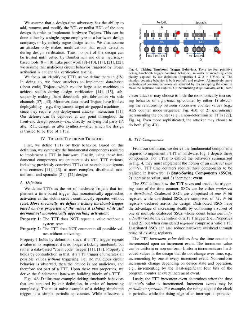
Figs. 4A–D illustrate example ticking timebomb behaviorsthat are captured by our definition, in order of increasingcomplexity. The most naive example of a ticking timebombtrigger is a simple periodic up-counter. While effective, a
Periodic Sporadic
Uniform
Non
-uniform
0 1 2 3…
X
9 3 5 8…
5ns
AES
A
B
X’
0 1 2 3 … X
…7ns 2ns 3ns
9 3 5 8
AES
C
D
X’
5ns 5ns
Fig. 4. Ticking Timebomb Trigger Behaviors. There are four primitiveticking timebomb trigger counting behaviors, in order of increasing com-plexity, captured by our definition (Properties 1 & 2 in §IV-A). A) Thesimplest counting behavior is both periodic and uniform. Alternatively, moresophisticated counting behaviors are achieved by: B) encrypting the count tomake the sequence non-uniform, C) incrementing it sporadically, or D) both.
clever attacker may choose to hide the monotonically increas-ing behavior of a periodic up-counter by either 1) obscur-ing the relationship between successive counter values (e.g.,AES counter mode sequence, Fig. 4B), or 2) sporadicallyincrementing the counter (e.g., a non-deterministic TTTs [22],Fig. 4). Even more sophisticated, the attacker may choose todo both (Fig. 4D).
B. TTT Components
From our definition, we derive the fundamental componentsrequired to implement a TTT in hardware. Fig. 1 depicts thesecomponents. For TTTs to exhibit the behaviors summarizedin Fig. 4, they must implement the notion of an abstract timecounter. TTT time counters require three components to berealized in hardware: 1) State-Saving Components (SSCs),2) increment value, and 3) increment event.
The SSC defines how the TTT saves and tracks the trigger-ing state of the time counter. SSCs can be either coalescedor distributed. Coalesced SSCs are comprised of one N -bitregister, while distributed SSCs are comprised of M , N -bitregisters declared across the design. Distributed SSCs havethe advantage of increasing stealth by combining a subset ofone or multiple coalesced SSCs whose count behaviors indi-vidually violate the definition of a TTT trigger (i.e., Properties1 and 2), but when considered together comprise a valid TTT.Distributed SSCs can also reduce hardware overhead throughreuse of existing registers.
The TTT increment value defines how the time counter isincremented upon an increment event. The increment valuecan be uniform or non-uniform. Uniform increments are hard-coded values in the design that do not change over time, e.g.,incrementing by one at every increment event. Non-uniformincrements change depending on device state and operation,e.g., incrementing by the least-significant four bits of theprogram counter at every increment event.
Lastly, the TTT increment event determines when the timecounter’s value is incremented. Increment events may beperiodic or sporadic. For example, the rising edge of the clockis periodic, while the rising edge of an interrupt is sporadic.
C. TTT Variants
From the behavior of the fundamental TTT components,we extrapolate six TTT variants that represent the TTT designspace as we define. We start by grouping TTTs accordingto their SSC construction. Depending on their sophisticationlevel, the attacker may choose to implement a simplisticcoalesced TTT, or construct a larger, more complex, dis-tributed TTT. If the attacker chooses to implement a coalescedTTT, they have four variants to choose from, with respect toincrement uniformity and periodicity. The most naive attackermay choose to implement a coalesced TTT with uniformincrement values and periodic increment events. To make thecoalesced TTT more difficult to identify, the attacker maychoose to implement non-uniform increment values and/orsporadic increment events.
To increase stealth, an attacker may choose to combine twoor more coalesced TTTs, that alone violate the definition ofbeing a TTT trigger, but combined construct a valid distributedTTT. An attacker has two design choices for distributed TTTs.Seeking to maximize stealth, the attacker may choose tocombine several copies of the same coalesced TTT with non-uniform increment values and sporadic increment events, thusimplementing a homogeneous distributed TTT. Alternatively,the attacker may seek integration flexibility, and choose tocombine various coalesced TTTs to implement a heteroge-neous distributed TTT. For homogeneous distributed TTTs,an attacker has the same four design choices as in coalescedTTTs. However, for heterogeneous distributed TTTs, the de-sign space is much larger. Specifically, the number of sub-categories of heterogeneous distributed TTTs can be computedusing the binomial expansion,
(nk
), with n, the number of
coalesced sub-triggers, and k, the number of unique sub-trigger types. We summarize all six TTT variants and theirbehaviors in Figs. 3 and 4, respectively, and provide exampleimplementations in Verilog in Appendix A.
V. BOMBERMAN
Now that we have defined what a TTT is, and howit behaves, how do we automatically locate them withincomplex RTL designs? To address this question, we designand implement Bomberman, a dynamic Trojan verificationframework.2 To summarize, Bomberman locates potentialTTTs by tracking the sequences expressed by all SSCs ina design, as SSCs are one of the fundamental buildingblocks of TTTs. Initially, Bomberman classifies all SSCs assuspicious. Then, any SSCs whose sequence progressions,recorded during simulation, violate either Properties in §IV-A,are marked benign.
Bomberman takes as input 1) a design’s HDL, and 2) veri-fication simulation results, and automatically flags suspicious
2Unfortunately, no commercial verification tool exists to track complex statethat defines TTT invariants, i.e., asserting no repeated values or distributedstate exhaustion. Moreover, the closest such tools—JasperGold [44] and VCFormal [45]—deploy bounded static analysis approaches that suffer fromstate-explosion when applied to such invariants.
Bomberman
A) SSC Identification
IVLFront-End
Data-FlowGraph
Generator(C++)
C++
API
Suspicious SSCs
SSC Enumeration
(Python)
.dot
B) SSC Classification
(Python)
.json
Verification (HDL Simulator)Random Input
Generator Output Checking
.vcd
.vcd
Verilog
Hardware Design (DUT)
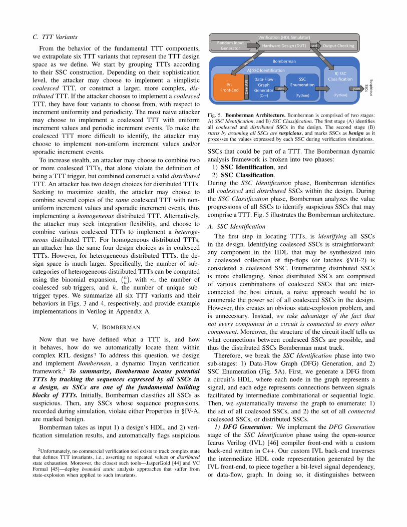
Fig. 5. Bomberman Architecture. Bomberman is comprised of two stages:A) SSC Identification, and B) SSC Classification. The first stage (A) identifiesall coalesced and distributed SSCs in the design. The second stage (B)starts by assuming all SSCs are suspicious, and marks SSCs as benign as itprocesses the values expressed by each SSC during verification simulations.
SSCs that could be part of a TTT. The Bomberman dynamicanalysis framework is broken into two phases:
1) SSC Identification, and2) SSC Classification.
During the SSC Identification phase, Bomberman identifiesall coalesced and distributed SSCs within the design. Duringthe SSC Classification phase, Bomberman analyzes the valueprogressions of all SSCs to identify suspicious SSCs that maycomprise a TTT. Fig. 5 illustrates the Bomberman architecture.
A. SSC Identification
The first step in locating TTTs, is identifying all SSCsin the design. Identifying coalesced SSCs is straightforward:any component in the HDL that may be synthesized intoa coalesced collection of flip-flops (or latches §VII-2) isconsidered a coalesced SSC. Enumerating distributed SSCsis more challenging. Since distributed SSCs are comprisedof various combinations of coalesced SSCs that are inter-connected the host circuit, a naive approach would be toenumerate the power set of all coalesced SSCs in the design.However, this creates an obvious state-explosion problem, andis unnecessary. Instead, we take advantage of the fact thatnot every component in a circuit is connected to every othercomponent. Moreover, the structure of the circuit itself tells uswhat connections between coalesced SSCs are possible, andthus the distributed SSCs Bomberman must track.
Therefore, we break the SSC Identification phase into twosub-stages: 1) Data-Flow Graph (DFG) Generation, and 2)SSC Enumeration (Fig. 5A). First, we generate a DFG froma circuit’s HDL, where each node in the graph represents asignal, and each edge represents connections between signalsfacilitated by intermediate combinational or sequential logic.Then, we systematically traverse the graph to enumerate: 1)the set of all coalesced SSCs, and 2) the set of all connectedcoalesced SSCs, or distributed SSCs.
1) DFG Generation: We implement the DFG Generationstage of the SSC Identification phase using the open-sourceIcarus Verilog (IVL) [46] compiler front-end with a customback-end written in C++. Our custom IVL back-end traversesthe intermediate HDL code representation generated by theIVL front-end, to piece together a bit-level signal dependency,or data-flow, graph. In doing so, it distinguishes between
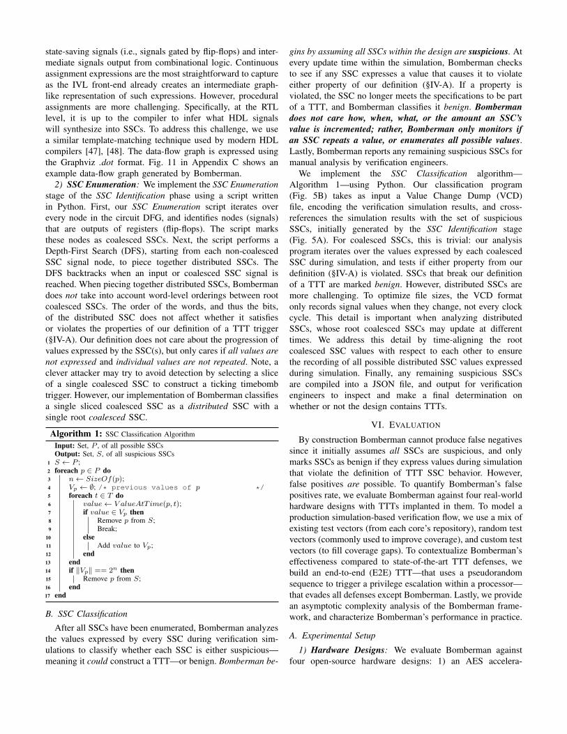
state-saving signals (i.e., signals gated by flip-flops) and inter-mediate signals output from combinational logic. Continuousassignment expressions are the most straightforward to captureas the IVL front-end already creates an intermediate graph-like representation of such expressions. However, proceduralassignments are more challenging. Specifically, at the RTLlevel, it is up to the compiler to infer what HDL signalswill synthesize into SSCs. To address this challenge, we usea similar template-matching technique used by modern HDLcompilers [47], [48]. The data-flow graph is expressed usingthe Graphviz .dot format. Fig. 11 in Appendix C shows anexample data-flow graph generated by Bomberman.
2) SSC Enumeration: We implement the SSC Enumerationstage of the SSC Identification phase using a script writtenin Python. First, our SSC Enumeration script iterates overevery node in the circuit DFG, and identifies nodes (signals)that are outputs of registers (flip-flops). The script marksthese nodes as coalesced SSCs. Next, the script performs aDepth-First Search (DFS), starting from each non-coalescedSSC signal node, to piece together distributed SSCs. TheDFS backtracks when an input or coalesced SSC signal isreached. When piecing together distributed SSCs, Bombermandoes not take into account word-level orderings between rootcoalesced SSCs. The order of the words, and thus the bits,of the distributed SSC does not affect whether it satisfiesor violates the properties of our definition of a TTT trigger(§IV-A). Our definition does not care about the progression ofvalues expressed by the SSC(s), but only cares if all values arenot expressed and individual values are not repeated. Note, aclever attacker may try to avoid detection by selecting a sliceof a single coalesced SSC to construct a ticking timebombtrigger. However, our implementation of Bomberman classifiesa single sliced coalesced SSC as a distributed SSC with asingle root coalesced SSC.
Algorithm 1: SSC Classification Algorithm
Input: Set, P , of all possible SSCsOutput: Set, S, of all suspicious SSCs
1 S ← P ;2 foreach p ∈ P do3 n← SizeOf(p);4 Vp ← ∅; /* previous values of p */5 foreach t ∈ T do6 value← V alueAtT ime(p, t);7 if value ∈ Vp then8 Remove p from S;9 Break;
10 else11 Add value to Vp;12 end13 end14 if ‖Vp‖ == 2n then15 Remove p from S;16 end17 end
B. SSC Classification
After all SSCs have been enumerated, Bomberman analyzesthe values expressed by every SSC during verification sim-ulations to classify whether each SSC is either suspicious—meaning it could construct a TTT—or benign. Bomberman be-
gins by assuming all SSCs within the design are suspicious. Atevery update time within the simulation, Bomberman checksto see if any SSC expresses a value that causes it to violateeither property of our definition (§IV-A). If a property isviolated, the SSC no longer meets the specifications to be partof a TTT, and Bomberman classifies it benign. Bombermandoes not care how, when, what, or the amount an SSC’svalue is incremented; rather, Bomberman only monitors ifan SSC repeats a value, or enumerates all possible values.Lastly, Bomberman reports any remaining suspicious SSCs formanual analysis by verification engineers.
We implement the SSC Classification algorithm—Algorithm 1—using Python. Our classification program(Fig. 5B) takes as input a Value Change Dump (VCD)file, encoding the verification simulation results, and cross-references the simulation results with the set of suspiciousSSCs, initially generated by the SSC Identification stage(Fig. 5A). For coalesced SSCs, this is trivial: our analysisprogram iterates over the values expressed by each coalescedSSC during simulation, and tests if either property from ourdefinition (§IV-A) is violated. SSCs that break our definitionof a TTT are marked benign. However, distributed SSCs aremore challenging. To optimize file sizes, the VCD formatonly records signal values when they change, not every clockcycle. This detail is important when analyzing distributedSSCs, whose root coalesced SSCs may update at differenttimes. We address this detail by time-aligning the rootcoalesced SSC values with respect to each other to ensurethe recording of all possible distributed SSC values expressedduring simulation. Finally, any remaining suspicious SSCsare compiled into a JSON file, and output for verificationengineers to inspect and make a final determination onwhether or not the design contains TTTs.
VI. EVALUATION
By construction Bomberman cannot produce false negativessince it initially assumes all SSCs are suspicious, and onlymarks SSCs as benign if they express values during simulationthat violate the definition of TTT SSC behavior. However,false positives are possible. To quantify Bomberman’s falsepositives rate, we evaluate Bomberman against four real-worldhardware designs with TTTs implanted in them. To model aproduction simulation-based verification flow, we use a mix ofexisting test vectors (from each core’s repository), random testvectors (commonly used to improve coverage), and custom testvectors (to fill coverage gaps). To contextualize Bomberman’seffectiveness compared to state-of-the-art TTT defenses, webuild an end-to-end (E2E) TTT—that uses a pseudorandomsequence to trigger a privilege escalation within a processor—that evades all defenses except Bomberman. Lastly, we providean asymptotic complexity analysis of the Bomberman frame-work, and characterize Bomberman’s performance in practice.
A. Experimental Setup
1) Hardware Designs: We evaluate Bomberman againstfour open-source hardware designs: 1) an AES accelera-
A) AES B) UART C) RISC-V D) OR1200
Test Bench Controller
AES (DUT)
Plaintext LFSR
ciphertext
Key LFSR Verify
Test Bench Controller
Wishbone Bus
UART Encoder
UART Decoder
UART (DUT)
Data LFSR
RX TX
Verify
RISC-V CPU(DUT) Memory
Test Bench Controller
.exe
AXI-4 Lite Bus
Execution MonitorVerify
Test Bench Controller
OR1200 CPU(DUT)UART Memory
UART Decoder
.exe
Wishbone Bus
Verify
Execution Monitor
TX
Verify
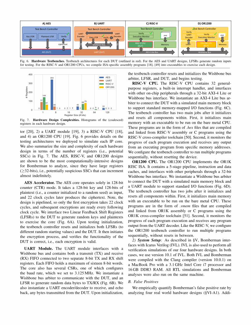
Fig. 6. Hardware Testbenches. Testbench architectures for each DUT (outlined in red). For the AES and UART designs, LFSRs generate random inputsfor testing. For the RISC-V and OR1200 CPUs, we compile ISA-specific assembly programs [18], [49] into executables to exercise each design.
1 8 16 32 64 128Register Size (# bits)
0
100
200
300
400
# R
egis
ters
0
91
144
61
344
40
1 0 0 2 1 440
2
68 79
0 0 8 222
0 0 0
AESUARTRISC-VOR1200
Fig. 7. Hardware Design Complexities. Histograms of the (coalesced)registers in each hardware design.
tor [20], 2) a UART module [19], 3) a RISC-V CPU [18],and 4) an OR1200 CPU [19]. Fig. 6 provides details on thetesting architectures we deployed to simulate each IP core.We also summarize the size and complexity of each hardwaredesign in terms of the number of registers (i.e., potentialSSCs) in Fig. 7. The AES, RISC-V, and OR1200 designsare shown to be the most computationally-intensive designsfor Bomberman to analyze, since they have large registers(≥32-bits), i.e., potentially suspicious SSCs that can incrementalmost indefinitely.
AES Accelerator. The AES core operates solely in 128-bitcounter (CTR) mode. It takes a 128-bit key and 128-bits ofplaintext (i.e., a counter initialized to a random seed) as input,and 22 clock cycles later produces the ciphertext. Note, thedesign is pipelined, so only the first encryption takes 22 clockcycles, and subsequent encryptions are ready every followingclock cycle. We interface two Linear Feedback Shift Registers(LFSRs) to the DUT to generate random keys and plaintextsto exercise the core (Fig. 6A). Upon testing initialization,the testbench controller resets and initializes both LFSRs (todifferent random starting values) and the DUT. It then initiatesthe encryption process, and verifies the functionality of theDUT is correct, i.e., each encryption is valid.
UART Module. The UART module interfaces with aWishbone bus and contains both a transmit (TX) and receive(RX) FIFO connected to two separate 8-bit TX and RX shiftregisters. Each FIFO holds a maximum of sixteen 8-bit words.The core also has several CSRs, one of which configuresthe baud rate, which we set to 3.125 MHz. We instantiate aWishbone bus arbiter to communicate with the DUT, and anLFSR to generate random data bytes to TX/RX (Fig. 6B). Wealso instantiate a UART encoder/decoder to receive, and echoback, any bytes transmitted from the DUT. Upon initialization,
the testbench controller resets and initializes the Wishbone busarbiter, LFSR, and DUT, and begins testing.
RISC-V CPU. The RISC-V CPU contains 32 general-purpose registers, a built-in interrupt handler, and interfaceswith other on-chip peripherals through a 32-bit AXI-4 Lite orWishbone bus interface. We instantiate an AXI-4 Lite bus ar-biter to connect the DUT with a simulated main memory blockto support standard memory-mapped I/O functions (Fig. 6C).The testbench controller has two main jobs after it initializesand resets all components within. First, it initializes mainmemory with an executable to be run on the bare metal CPU.These programs are in the form of .hex files that are compiledand linked from RISC-V assembly or C programs using theRISC-V cross-compiler toolchain [50]. Second, it monitors theprogress of each program execution and receives any outputfrom an executing program from specific memory addresses.We configure the testbench controller to run multiple programssequentially, without resetting the device.
OR1200 CPU. The OR1200 CPU implements the OR1KRISC ISA. It contains a 5-stage pipeline, instruction and datacaches, and interfaces with other peripherals through a 32-bitWishbone bus interface. We instantiate a Wishbone bus arbiterto connect the DUT with a simulated main memory block anda UART module to support standard I/O functions (Fig. 6D).The testbench controller has two jobs after it initializes andresets all components within. First, it initializes main memorywith an executable to be run on the bare metal CPU. Theseprograms are in the form of .vmem files that are compiledand linked from OR1K assembly or C programs using theOR1K cross-compiler toolchain [51]. Second, it monitors theprogress of each program execution and receives any programoutput from the UART decoder. Like the RISC-V, we configurethe OR1200 testbench controller to run multiple programssequentially, without resets in between.
2) System Setup: As described in §V, Bomberman inter-faces with Icarus Verilog (IVL). IVL is also used to perform allverification simulations of our four hardware designs. In bothcases, we use version 10.1 of IVL. Both IVL and Bombermanwere compiled with the Clang compiler (version 10.0.1) ona MacBook Pro with a 3.1 GHz Intel Core i7 processor and16 GB DDR3 RAM. All RTL simulations and Bombermananalyses were also run on the same machine.
B. False Positives
We empirically quantify Bomberman’s false positive rate byanalyzing four real world hardware designs (§VI-A1). Addi-
A) AES
C) RISC-V
B) UART
D) OR1200
Repeat 75 Encryptions75 Random Encryptions
Found6 SSCs
Erro
r Tes
ting
TX 1
6 By
tes
RX 1
6 By
tes
Repe
at T
X 16
Byt
es
Repe
at R
X 16
Byt
es
Found 6 SSCs
dsx
insn
fetc
herr
or ov
shortjump
ticks
ysca
ll
dsx
insn
fetc
herr
or ov
shortjump ticks
ysca
ll
custom*
Foun
d 9
SSCs
custom*
lsu lsu
lwjr
lwjr
Jum
p In
s.
Bran
ch In
s.
Load
Ins.
Stor
e In
s.
Int.
Reg.
-Imm
ed. I
ns.
Int.
Reg.
-Reg
. Ins
.
Mul
tiply
Ins.
Divi
de In
s.
Found 19 SSCs
Debu
g In
s.
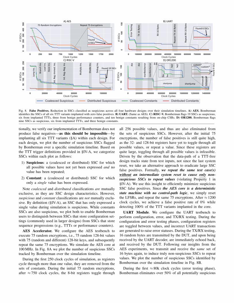
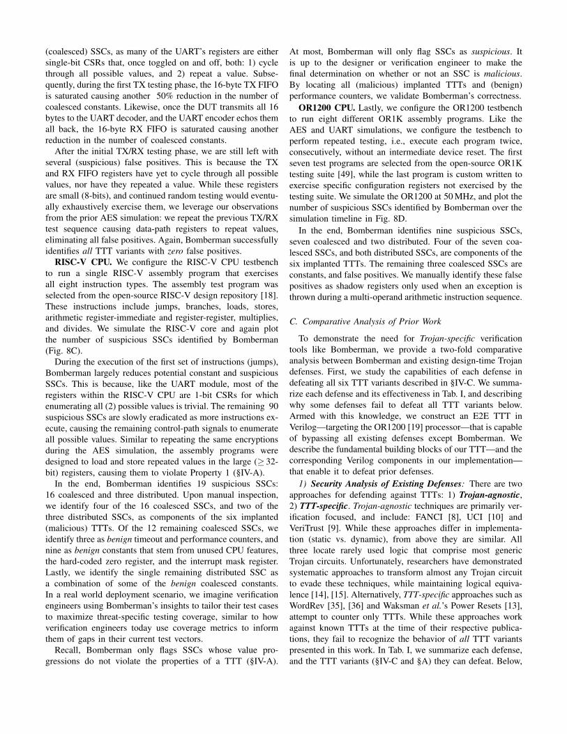
Fig. 8. False Positives. Reduction in SSCs classified as suspicious across all four hardware designs over their simulation timelines. A) AES. Bombermanidentifies the SSCs of all six TTT variants implanted with zero false positives. B) UART. (Same as AES). C) RISC-V. Bomberman flags 19 SSCs as suspicious,six from implanted TTTs, three from benign performance counters, and ten benign constants resulting from on-chip CSRs. D) OR1200. Bomberman flagsnine SSCs as suspicious, six from implanted TTTs, and three benign constants.
tionally, we verify our implementation of Bomberman does notproduce false negatives—as this should be impossible—byimplanting all six TTT variants (§A) within each design. Foreach design, we plot the number of suspicious SSCs flaggedby Bomberman over a specific simulation timeline. Based onthe TTT trigger definitions provided in §IV-A, we categorizeSSCs within each plot as follows:
1) Suspicious: a (coalesced or distributed) SSC for whichall possible values have not yet been expressed and novalue has been repeated;
2) Constant: a (coalesced or distributed) SSC for whichonly a single value has been expressed.
Note coalesced and distributed classifications are mutuallyexclusive, as they are SSC design characteristics. However,suspicious and constant classifications are not mutually exclu-sive. By definition (§IV-A), an SSC that has only expressed asingle value during simulation is suspicious. While constantsSSCs are also suspicious, we plot both to enable Bombermanusers to distinguish between SSCs that store configuration set-tings (commonly used in larger designs) from SSCs that storesequence progressions (e.g., TTTs or performance counters).
AES Accelerator. We configure the AES testbench toexecute 75 random encryptions, i.e., 75 random 128-bit valueswith 75 (random and different) 128-bit keys, and subsequentlyrepeat the same 75 encryptions. We simulate the AES core at100 MHz. In Fig. 8A we plot the number of suspicious SSCstracked by Bomberman over the simulation timeline.
During the first 250 clock cycles of simulation, as registerscycle through more than one value, they are removed from thesets of constants. During the initial 75 random encryptions,after ≈ 750 clock cycles, the 8-bit registers toggle through
all 256 possible values, and thus are also eliminated fromthe sets of suspicious SSCs. However, after the initial 75encryptions, the number of false positives is still quite high,as the 32- and 128-bit registers have yet to toggle through allpossible values, or repeat a value. Since these registers arequite large, toggling through all possible values is infeasible.Driven by the observation that the data-path of a TTT-freedesign tracks state from test inputs, not since the last systemreset, we take an alternative approach to eradicate large SSCfalse positives. Formally, we repeat the same test case(s)without an intermediate system reset to cause only non-suspicious SSCs to repeat values (violating Property 1 in§IV-A). We use this insight to efficiently minimize suspiciousSSC false positives. Since the AES core is a deterministicstate machine with no control-path logic, we simply resetthe LFSRs, and repeat the same 75 encryptions. After ≈ 1200clock cycles, we achieve a false positive rate of 0% whiledetecting 100% of the TTT variants implanted in the core.
UART Module. We configure the UART testbench toperform configuration, error, and TX/RX testing. During theconfiguration and error testing phases, configuration registersare toggled between values, and incorrect UART transactionsare generated to raise error statuses. During the TX/RX testing,16 random bytes are transmitted by the DUT, and upon beingreceived by the UART decoder, are immediately echoed back,and received by the DUT. Following our insights from theAES experiments, we transmit and receive the same set of16 bytes again, to induce truly non-suspicious SSCs to repeatvalues. We plot the number of suspicious SSCs identified byBomberman over the simulation timeline in Fig. 8B.
During the first ≈ 80k clock cycles (error testing phase),Bomberman eliminates over 50% of all potentially suspicious
(coalesced) SSCs, as many of the UART’s registers are eithersingle-bit CSRs that, once toggled on and off, both: 1) cyclethrough all possible values, and 2) repeat a value. Subse-quently, during the first TX testing phase, the 16-byte TX FIFOis saturated causing another 50% reduction in the number ofcoalesced constants. Likewise, once the DUT transmits all 16bytes to the UART decoder, and the UART encoder echos themall back, the 16-byte RX FIFO is saturated causing anotherreduction in the number of coalesced constants.
After the initial TX/RX testing phase, we are still left withseveral (suspicious) false positives. This is because the TXand RX FIFO registers have yet to cycle through all possiblevalues, nor have they repeated a value. While these registersare small (8-bits), and continued random testing would eventu-ally exhaustively exercise them, we leverage our observationsfrom the prior AES simulation: we repeat the previous TX/RXtest sequence causing data-path registers to repeat values,eliminating all false positives. Again, Bomberman successfullyidentifies all TTT variants with zero false positives.
RISC-V CPU. We configure the RISC-V CPU testbenchto run a single RISC-V assembly program that exercisesall eight instruction types. The assembly test program wasselected from the open-source RISC-V design repository [18].These instructions include jumps, branches, loads, stores,arithmetic register-immediate and register-register, multiplies,and divides. We simulate the RISC-V core and again plotthe number of suspicious SSCs identified by Bomberman(Fig. 8C).
During the execution of the first set of instructions (jumps),Bomberman largely reduces potential constant and suspiciousSSCs. This is because, like the UART module, most of theregisters within the RISC-V CPU are 1-bit CSRs for whichenumerating all (2) possible values is trivial. The remaining 90suspicious SSCs are slowly eradicated as more instructions ex-ecute, causing the remaining control-path signals to enumerateall possible values. Similar to repeating the same encryptionsduring the AES simulation, the assembly programs weredesigned to load and store repeated values in the large (≥ 32-bit) registers, causing them to violate Property 1 (§IV-A).
In the end, Bomberman identifies 19 suspicious SSCs:16 coalesced and three distributed. Upon manual inspection,we identify four of the 16 coalesced SSCs, and two of thethree distributed SSCs, as components of the six implanted(malicious) TTTs. Of the 12 remaining coalesced SSCs, weidentify three as benign timeout and performance counters, andnine as benign constants that stem from unused CPU features,the hard-coded zero register, and the interrupt mask register.Lastly, we identify the single remaining distributed SSC asa combination of some of the benign coalesced constants.In a real world deployment scenario, we imagine verificationengineers using Bomberman’s insights to tailor their test casesto maximize threat-specific testing coverage, similar to howverification engineers today use coverage metrics to informthem of gaps in their current test vectors.
Recall, Bomberman only flags SSCs whose value pro-gressions do not violate the properties of a TTT (§IV-A).
At most, Bomberman will only flag SSCs as suspicious. Itis up to the designer or verification engineer to make thefinal determination on whether or not an SSC is malicious.By locating all (malicious) implanted TTTs and (benign)performance counters, we validate Bomberman’s correctness.
OR1200 CPU. Lastly, we configure the OR1200 testbenchto run eight different OR1K assembly programs. Like theAES and UART simulations, we configure the testbench toperform repeated testing, i.e., execute each program twice,consecutively, without an intermediate device reset. The firstseven test programs are selected from the open-source OR1Ktesting suite [49], while the last program is custom written toexercise specific configuration registers not exercised by thetesting suite. We simulate the OR1200 at 50 MHz, and plot thenumber of suspicious SSCs identified by Bomberman over thesimulation timeline in Fig. 8D.
In the end, Bomberman identifies nine suspicious SSCs,seven coalesced and two distributed. Four of the seven coa-lesced SSCs, and both distributed SSCs, are components of thesix implanted TTTs. The remaining three coalesced SSCs areconstants, and false positives. We manually identify these falsepositives as shadow registers only used when an exception isthrown during a multi-operand arithmetic instruction sequence.
C. Comparative Analysis of Prior Work
To demonstrate the need for Trojan-specific verificationtools like Bomberman, we provide a two-fold comparativeanalysis between Bomberman and existing design-time Trojandefenses. First, we study the capabilities of each defense indefeating all six TTT variants described in §IV-C. We summa-rize each defense and its effectiveness in Tab. I, and describingwhy some defenses fail to defeat all TTT variants below.Armed with this knowledge, we construct an E2E TTT inVerilog—targeting the OR1200 [19] processor—that is capableof bypassing all existing defenses except Bomberman. Wedescribe the fundamental building blocks of our TTT—and thecorresponding Verilog components in our implementation—that enable it to defeat prior defenses.
1) Security Analysis of Existing Defenses: There are twoapproaches for defending against TTTs: 1) Trojan-agnostic,2) TTT-specific. Trojan-agnostic techniques are primarily ver-ification focused, and include: FANCI [8], UCI [10] andVeriTrust [9]. While these approaches differ in implementa-tion (static vs. dynamic), from above they are similar. Allthree locate rarely used logic that comprise most genericTrojan circuits. Unfortunately, researchers have demonstratedsystematic approaches to transform almost any Trojan circuitto evade these techniques, while maintaining logical equiva-lence [14], [15]. Alternatively, TTT-specific approaches such asWordRev [35], [36] and Waksman et al.’s Power Resets [13],attempt to counter only TTTs. While these approaches workagainst known TTTs at the time of their respective publica-tions, they fail to recognize the behavior of all TTT variantspresented in this work. In Tab. I, we summarize each defense,and the TTT variants (§IV-C and §A) they can defeat. Below,
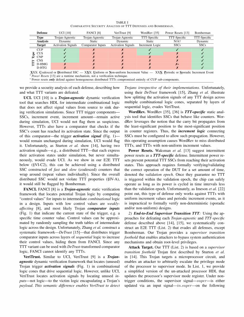
TABLE ICOMPARATIVE SECURITY ANALYSIS OF TTT DEFENSES AND BOMBERMAN.
Defense UCI [10] FANCI [8] VeriTrust [9] WordRev [35] Power Resets [13] BombermanType Trojan-Agnostic Trojan-Agnostic Trojan-Agnostic TTT-Specific TTT-Specific TTT-SpecificAnalysis Dynamic Static Dynamic Static N/A† DynamicTarget Activation Signals Comparator Inputs Activation Signals Increment Logic SSCs SSCs
TT
TTy
pe
CUP 3 7 7 3 3 3CUS 3 7 7 3 7 3CNP 3 7 7 7 7 3CNS 3 7 7 7 7 3D-HMG 7 7 7 7 7* 3D-HTG 7 7 7 7 7 3
XXX: Coalesced or Distributed SSC — XXX: Uniform or Non-uniform Increment Value — XXX: Periodic or Sporadic Increment Event† Power Resets [13] are a runtime mechanism, not a verification technique.* Power resets only defend against homogeneous distributed TTTs compromised entirely of CUP sub-components.
we provide a security analysis of each defense, describing howand what TTT variants are defeated.
UCI. UCI [10] is a Trojan-agnostic dynamic verificationtool that searches HDL for intermediate combinational logicthat does not affect signal values from source to sink dur-ing verification simulations. Since TTT trigger components—SSCs, increment event, increment amount—remain activeduring simulation, UCI would not flag them as suspicious.However, TTTs also have a comparator that checks if theSSC’s count has reached its activation state. Since the outputof this comparator—the trigger activation signal (Fig. 1)—would remain unchanged during simulation, UCI would flagit. Unfortunately, as Sturton et al. show [14], having twoactivation signals—e.g., a distributed TTT—that each expresstheir activation states under simulation, but never simulta-neously, would evade UCI. As we show in our E2E TTTbelow (§VI-C2), this can be achieved using a distributedSSC constructed of fast and slow (coalesced) counters thatwrap around (repeat values individually). Since the overalldistributed SSC would not violate TTT properties (§IV-A),it would still be flagged by Bomberman.
FANCI. FANCI [8] is a Trojan-agnostic static verificationframework that locates potential Trojan logic by computing“control values” for inputs to intermediate combinational logicin a design. Inputs with low control values are weakly-affecting [8], and most likely Trojan comparator inputs(Fig. 1) that indicate the current state of the trigger, e.g. aspecific time counter value. Control values can be approxi-mated by randomly sampling the truth tables of intermediatelogic across the design. Unfortunately, Zhang et al. construct asystematic framework—DeTrust [15]—that distributes triggercomparator inputs across layers of sequential logic to increasetheir control values, hiding them from FANCI. Since anyTTT variant can be used with DeTrust-transformed comparatorlogic, FANCI cannot identify any TTTs.
VeriTrust. Similar to UCI, VeriTrust [9] is a Trojan-agnostic dynamic verification framework that locates (unused)Trojan trigger activation signals (Fig. 1) in combinationallogic cones that drive sequential logic. However, unlike UCI,VeriTrust locates activation signals by locating unused in-puts—not logic—to the victim logic encapsulating a Trojan’spayload. This semantic difference enables VeriTrust to detect
Trojans irrespective of their implementations. Unfortunately,using their DeTrust framework [15], Zhang et al. illustratehow splitting the activation signals of any TTT design acrossmultiple combinational logic cones, separated by layers ofsequential logic, evades VeriTrust.
WordRev. WordRev [35], [36] is TTT-specific static anal-ysis tool that identifies SSCs that behave like counters. Wor-dRev leverages the notion that the carry bit propagates fromthe least-significant position to the most-significant positionin counter registers. Thus, the increment logic connectingSSCs must be configured to allow such propagation. However,this operating assumption causes WordRev to miss distributedTTTs, and TTTs with non-uniform increment values.
Power Resets. Waksman et al. [13] suggest intermittentpower resets as a TTT-specific defense. Intermittent power re-sets prevent potential TTT SSCs from reaching their activationstates. This approach requires formally verifying/validatingthe correct operation of the DUT for a set amount of time,denoted the validation epoch. Once they guarantee no TTTis triggered within the validation epoch, the chip can safelyoperate as long as its power is cycled in time intervals lessthan the validation epoch. Unfortunately, as Imeson et al. [22]point out, this type of defense only works against TTTs withuniform increment values and periodic increment events, as itis impractical to formally verify non-deterministic (sporadicand/or non-uniform) designs.
2) End-to-End Supervisor Transition TTT: Using the ap-proaches for defeating each Trojan-agnostic and TTT-specificdefense described above [14], [15], we systematically con-struct an E2E TTT (List. 2) that evades all defenses, exceptBomberman. Our Trojan provides a supervisor transitionfoothold that enables attackers to bypass system authenticationmechanisms and obtain root-level privileges.
Attack Target. Our TTT (List. 2) is based on a supervisortransition foothold Trojan first described by Sturton et al.in [14]. This Trojan targets a microprocessor circuit, andenables an attacker to arbitrarily escalate the privilege modeof the processor to supervisor mode. In List. 1, we providea simplified version of the un-attacked processor HDL thatupdates the processor’s supervisor mode register. Under non-trigger conditions, the supervisor signal—super—is eitherupdated via an input signal—in.super—on the following
clock edge, if the holdn bit is 1 (holdn is active low),otherwise the super signal holds the same value from theprevious clock period. Additionally, the super signal is resetto 1 (supervisor mode) when the processor is reset via theactive-low resetn signal.
Listing 1. Unmodified HDL of the processor’s supervisor-mode update logic.
1 always @(posedge clk) begin2 super <= ∼resetn | (∼holdn & super) | (holdn & in.super) ;3 end
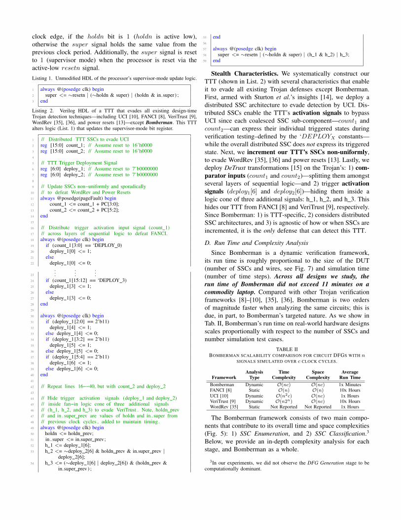
Listing 2. Verilog HDL of a TTT that evades all existing design-timeTrojan detection techniques—including UCI [10], FANCI [8], VeriTrust [9],WordRev [35], [36], and power resets [13]—except Bomberman. This TTTalters logic (List. 1) that updates the supervisor-mode bit register.
1 // Distributed TTT SSCs to evade UCI2 reg [15:0] count 1; // Assume reset to 16’h00003 reg [15:0] count 2; // Assume reset to 16’h00004
5 // TTT Trigger Deployment Signal6 reg [6:0] deploy 1; // Assume reset to 7’b00000007 reg [6:0] deploy 2; // Assume reset to 7’b00000008
9 // Update SSCs non−uniformly and sporadically10 // to defeat WordRev and Power Resets11 always @posedge(pageFault) begin12 count 1 <= count 1 + PC[3:0];13 count 2 <= count 2 + PC[5:2];14 end15
16 // Distribute trigger activation input signal (count 1)17 // across layers of sequential logic to defeat FANCI.18 always @(posedge clk) begin19 if (count 1 [3:0] == ‘DEPLOY 0)20 deploy 1[0] <= 1;21 else22 deploy 1[0] <= 0;
23
......
...24 if (count 1[15:12] == ‘DEPLOY 3)25 deploy 1[3] <= 1;26 else27 deploy 1[3] <= 0;28 end29
30 always @(posedge clk) begin31 if (deploy 1[2:0] == 2’b11)32 deploy 1[4] <= 1;33 else deploy 1[4] <= 0;34 if (deploy 1[3:2] == 2’b11)35 deploy 1[5] <= 1;36 else deploy 1[5] <= 0;37 if (deploy 1[5:4] == 2’b11)38 deploy 1[6] <= 1;39 else deploy 1[6] <= 0;40 end41
42 // Repeat lines 16−−40, but with count 2 and deploy 243
44 // Hide trigger activation signals (deploy 1 and deploy 2)45 // inside fan−in logic cone of three additional signals46 // (h 1, h 2, and h 3) to evade VeriTrust . Note, holdn prev47 // and in . super prev are values of holdn and in . super from48 // previous clock cycles , added to maintain timing .49 always @(posedge clk) begin50 holdn <= holdn prev;51 in . super <= in.super prev;52 h 1 <= deploy 1[6];53 h 2 <= ∼deploy 2[6] & holdn prev & in.super prev |
deploy 2[6];54 h 3 <= (∼deploy 1[6] | deploy 2[6]) & (holdn prev &
in.super prev) ;
55 end56
57 always @(posedge clk) begin58 super <= ∼resetn | (∼holdn & super) | (h 1 & h 2) | h 3;59 end
Stealth Characteristics. We systematically construct ourTTT (shown in List. 2) with several characteristics that enableit to evade all existing Trojan defenses except Bomberman.First, armed with Sturton et al.’s insights [14], we deploy adistributed SSC architecture to evade detection by UCI. Dis-tributed SSCs enable the TTT’s activation signals to bypassUCI since each coalesced SSC sub-component—count1 andcount2—can express their individual triggered states duringverification testing–defined by the ‘DEPLOYX constants—while the overall distributed SSC does not express its triggeredstate. Next, we increment our TTT’s SSCs non-uniformly,to evade WordRev [35], [36] and power resets [13]. Lastly, wedeploy DeTrust transformations [15] on the Trojan’s: 1) com-parator inputs (count1 and count2)—splitting them amongstseveral layers of sequential logic—and 2) trigger activationsignals (deploy1[6] and deploy2[6])—hiding them inside alogic cone of three additional signals: h 1, h 2, and h 3. Thishides our TTT from FANCI [8] and VeriTrust [9], respectively.Since Bomberman: 1) is TTT-specific, 2) considers distributedSSC architectures, and 3) is agnostic of how or when SSCs areincremented, it is the only defense that can detect this TTT.
D. Run Time and Complexity Analysis
Since Bomberman is a dynamic verification framework,its run time is roughly proportional to the size of the DUT(number of SSCs and wires, see Fig. 7) and simulation time(number of time steps). Across all designs we study, therun time of Bomberman did not exceed 11 minutes on acommodity laptop. Compared with other Trojan verificationframeworks [8]–[10], [35], [36], Bomberman is two ordersof magnitude faster when analyzing the same circuits; this isdue, in part, to Bomberman’s targeted nature. As we show inTab. II, Bomberman’s run time on real-world hardware designsscales proportionally with respect to the number of SSCs andnumber simulation test cases.
TABLE IIBOMBERMAN SCALABILITY COMPARISON FOR CIRCUIT DFGS WITH n
SIGNALS SIMULATED OVER c CLOCK CYCLES.
Analysis Time Space AverageFramework Type Complexity Complexity Run Time
Bomberman Dynamic O(nc) O(nc) 1x MinutesFANCI [8] Static O(n) O(n) 10x HoursUCI [10] Dynamic O(n2c) O(nc) 1x HoursVeriTrust [9] Dynamic O(n2n) O(nc) 10x HoursWordRev [35] Static Not Reported Not Reported 1x Hours
The Bomberman framework consists of two main compo-nents that contribute to its overall time and space complexities(Fig. 5): 1) SSC Enumeration, and 2) SSC Classification.3
Below, we provide an in-depth complexity analysis for eachstage, and Bomberman as a whole.
3In our experiments, we did not observe the DFG Generation stage to becomputationally dominant.
0 10 20 30 40 50Pipeline Logic Depth
AES
UART
OR1200
RISC-V
ARM CORTEX-M0
Des
ign
Bomberman RT: 5.457s
Bomberman RT: 4.912s
Bomberman RT: 22.570s
Bomberman RT: 10.840s
Bomberman RT: 643.568s
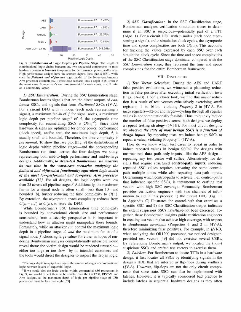
Fig. 9. Distributions of Logic Depths per Pipeline Stage. The length ofcombinational logic chains between any two sequential components in mosthardware designs is bounded to optimize for performance, power, and/or area.High performance designs have the shortest depths (less than 8 [53]), whileeven the flattened and obfuscated logic model of the lowest-performanceArm processor available [52] (worst case scenario) has a depth <25. Even inthe worst case, Bomberman’s run time (overlaid for each core), is <11 min.on a commodity laptop.
1) SSC Enumeration: During the SSC Enumeration stage,Bomberman locates signals that are the direct outputs of coa-lesced SSCs, and signals that form distributed SSCs (§V-A).For a circuit DFG with n nodes (each node representing asignal), a maximum fan-in of f for signal nodes, a maximumlogic depth per pipeline stage4 of d, the asymptotic timecomplexity for enumerating SSCs is O(nfd). Since mosthardware designs are optimized for either power, performance(clock speed), and/or area, the maximum logic depth, d, isusually small and bounded. Therefore, the time complexity ispolynomial. To show this, we plot (Fig. 9) the distributions oflogic depths within pipeline stages—and the correspondingBomberman run time—across the four designs we study,representing both mid-to-high performance and mid-to-largedesigns. Additionally, to stress-test Bomberman, we measureits run time in the worst-case scenario: analyzing theflattened and obfuscated functionally-equivalent logic modelof the most low-performant and low-power Arm processoravailable [52]. For all designs, the logic depths were lessthan 25 across all pipeline stages.5 Additionally, the maximumfan-in for a signal node is often small—less than 10—andbounded [8], further reducing the time complexity to O(n).By extension, the asymptotic space complexity reduces fromO(n+ nf) to O(n), to store the DFG.
While Bomberman’s SSC Enumeration time complexityis bounded by conventional circuit size and performanceconstraints, from a security perspective it is important tounderstand how an attacker might manipulate these bounds.Fortunately, while an attacker can control the maximum logicdepth in a pipeline stage, d, and the maximum fan-in of asignal node, f , choosing large values for either in hopes of ren-dering Bomberman analyses computationally infeasible wouldreveal them: the victim design would be rendered unusable—either too large or too slow—by its intended customers andthe tools would direct the designer to inspect the Trojan logic.
4The logic depth in a pipeline stage is the number of stages of combinationallogic between layers of sequential logic.
5If we could plot the logic depths within commercial x86 processors inFig. 9, we would expect them to be smaller than the OR1200, RISC-V, andArm designs, as the maximum depth of logic per pipeline stage of GHzprocessors must be less than eight [53].
2) SSC Classification: In the SSC Classification stage,Bomberman analyzes verification simulation traces to deter-mine if an SSC is suspicious—potentially part of a TTT(Algo. 1). For a circuit DFG with n nodes (each node repre-senting a signal), and c simulation clock cycles, the asymptotictime and space complexities are both O(nc). This accountsfor tracking the values expressed by each SSC over eachsimulation clock cycle. Since the time and space complexitiesof the SSC Classification stage dominate, compared with theSSC Enumeration stage, they represent the time and spacecomplexities for the entire Bomberman framework.
VII. DISCUSSION
1) Test Vector Selection: During the AES and UARTfalse positive evaluations, we witnessed a plateauing reduc-tion in false positives after executing initial verification tests(Figs. 8A–B). Upon a closer look, we find this initial reduc-tion is a result of test vectors exhaustively exercising smallregisters—1- to 16-bit—violating Property 2 in §IV-A. Forlarge registers—32-bit and larger—cycling through all registervalues is not computationally feasible. Thus, to quickly reducethe number of false positives across both designs, we deploya repeat testing strategy (§VI-B). For most circuit designs,we observe: the state of most benign SSCs is a function ofdesign inputs. By repeating tests, we induce benign SSCs torepeat a value, violating Property 1 (§IV-A).
How do we know which test cases to repeat in order toinduce repeated values in benign SSCs? For designs withunstructured, data-path-only inputs—like the AES design—repeating any test vector will suffice. Alternatively, for de-signs that require structured control-path inputs, inducingrepeated SSC values requires activating the same control-path multiple times while also repeating data-path inputs.Determining which control-paths to activate, i.e., control-pathsthat influence specific SSCs, is tantamount to crafting testvectors with high SSC coverage. Fortunately, Bombermanprovides verification engineers with two channels of infor-mation to aid in this process: 1) the circuit DFG (Fig. 11in Appendix C) illustrates the control-path that exercises aspecific SSC, and 2) the SSC Classification output indicatesthe extent suspicious SSCs have/have-not been exercised. To-gether, these Bomberman insights guide verification engineersin creating test vectors that achieve high coverage, with respectto Bomberman invariants (Properties 1 and 2 in §IV-A),therefore minimizing false positives. For example, in §VI-B,when analyzing the OR1200 processor, we noticed designer-provided test vectors [49] did not exercise several CSRs.By referencing Bomberman’s output, we located the (non-)suspicious SSCs and crafted test vectors to exercise them.
2) Latches: For Bomberman to locate TTTs in a hardwaredesign, it first locates all SSCs by identifying signals in thedesign’s HDL that are inferred as flip-flops during synthesis(§V-A). However, flip-flops are not the only circuit compo-nents that store state. SSCs can also be implemented withlatches. However, it is typically considered bad practice toinclude latches in sequential hardware designs as they often
induce unwanted timing errors. As a result, HDL compilers insynthesis CAD tools issue warnings when they infer latchesin a design—highlighting the TTT. Nonetheless, to supportsuch (bad) design practices, we design Bomberman’s data-flowgraph generation compiler back-end to also recognize latches.
3) TTT Identification in Physical Layouts: Bombermanis designed as an extension into existing front-end verificationtool-chains that process hardware designs (Fig. 2). Under adifferent threat model—one encapsulating untrusted back-enddesigners—it may be necessary to analyze physical layouts forthe presence of TTTs. Bomberman can analyze physical lay-outs for TTTs, provided the layout (GDSII) file is first reverse-engineered into a gate-level netlist. As noted by Yang etal. [28], there are several reverse-engineering tools for carryingout this task. Bomberman also requires HDL device modelsfor all devices in the netlist (e.g., NAND gate). This informsBomberman of a device’s input and output signals, which isrequired to create a DFG. Fortunately, HDL device modelsare typically provided as a part of the process technology IPportfolio purchased by front-end designers.
4) Memories: Bomberman is designed to handle memories,or large arrays of SSCs, in the same fashion that it handlesflip-flop-based SSCs. Namely, Bomberman creates a DFGof the addressable words within a memory block to curbstate-explosion when locating distributed SSCs. For memoriesthat mandate word-aligned accesses, Bomberman generatesa coalesced SSC for every word. For memories that allowunaligned accesses—which represent a minority, i.e., partof two adjacent words could be addressed simultaneously,Bomberman generates a coalesced SSC for every word, andmultiple word-sized distributed SSCs created by sliding aword-sized window across every adjacent memory word pair.In either case, Bomberman’s DFG filtering mechanism greatlyreduces the overall set of potentially suspicious SSCs.
5) Limitations: Bomberman is capable of detecting allTTTs with zero false negatives, within the constraints ofour definition (§IV-A). However, these constraints imposelimitations. First, if an attacker knows Bomberman is in use,they may alter their Trojan to repeat a value to avoid detection.There are two ways they may do this: 1) add an extra state bitto the SSC(s) that does not repeat a value, or 2) add additionallogic that resets the SSC(s) upon recognizing specific circuitbehavior. The first design would be detected by Bombermansince, by definition, describes a distributed SSC. However, thesecond scenario describes a Trojan that, by definition, is a data-based (cheat code) Trojan [13] not a TTT. Therefore, it wouldnot be detected by Bomberman. Data-based Trojans [13]are better addressed by techniques that target rarely usedactivation signals [9], [10] or comparator inputs [8] (Tab. I).Second, Bomberman is incapable of detecting TTTs that useanalog SSCs, like the A2 Trojan [28], as there is no notion ofanalog SSCs in front-end designs.6 Detecting Trojans like A2
6While the non-deterministic (sporadic) TTTs proposed by Imeson etal. [22] do use non-simulatable analog behavior (i.e., phase noise) as anentropy source for the increment event, they do not use analog SSCs. Thus,they are detectable by Bomberman.
require knowledge of the physical layout of the circuit, andare best addressed during circuit layout [54].
VIII. RELATED WORK
The implantation, detection, and prevention of hardwareTrojans across hardware design phases have been widelystudied. Attacks range from design-time attacks [7], [22], [27],[55], to layout-level modifications at fabrication time [28]–[30]. On the defensive side, most work focuses on post-fabrication Trojan detection [37]–[43], [54], [56], [57], giventhat most hardware design houses are fab-less, and thereforemust outsource their designs for fabrication. However, ashardware complexity increases, reliance on 3rd-party IP [3]brings the trustworthiness of the design process into question.Thus, there is active work in both detection [8]–[10], [35],[36] and preventation [11], [13] of design-time Trojans.
On the attack side, King et al. [7] demonstrate embeddinghardware Trojans in a processor for the purpose of plantingfootholds for high-level exploitation in software. They demon-strate how small perturbations in a microprocessor’s hardwarecan be exploited to mount wide varieties of software-levelattacks. Lin et al. [27] propose a different class of hardwareTrojans, designed to expose a side-channel for leaking infor-mation. Specifically, they add flip-flops to an AES core to cre-ate a power side channel large enough to exfiltrate key bytes,but small enough that it resides below the device’s power noisemargin. While both attacks demonstrate different payloads,they both require triggering mechanisms to remain dormantduring verification and post-fabrication testing. Thankfully, ourdefense is payload-agnostic and trigger-specific. We focus ondetecting hardware Trojans by their trigger. As a byproduct,we can identify any payloads by inspecting portions of thedesign that the trigger output influences.
Wang et al. [21] propose the first variant of sporadic TTTs,called Asynchronous Counter Trojans. Asynchronous CounterTrojans increment pseudo-randomly from a non-periodic in-ternal event signal (e.g., Fig. 4C and D). Similarly, Imesonet al. [22] propose non-deterministic TTTs. Non-deterministicTTTs are also sporadic, but they differ from pseudo-randomTTTs in that their event signals are not a function of thestate of the victim device, rather, they are a function of atrue source of entropy. Unlike, Waksman et al.’s power resetdefense [13], this nuance is irrelevant to Bomberman, whoidentifies TTTs by the values expressed by their SSCs, notthe source or predictability of their event signals.
On the defensive side, both design- and run-time approacheshave been proposed. At design-time, Hicks et al. [10] proposea dynamic analysis technique for Unused Circuit Identifica-tion (UCI) to locate potential trigger logic. After verificationtesting, they replace all unused logic with logic to raiseexceptions at run-time to be handled in software. Similarly,Zhang et al. [9] propose VeriTrust, a dynamic analysis tech-nique focused on the behavioral functionality, rather thanimplementation, of the hardware. Conversely, Waksman etal. [8] propose FANCI, a static analysis technique for locatingrarely used logic based on computing control values between
inputs and outputs. Lastly, Li and Subramanyan et al. [35],[36] propose WordRev, a different static analysis approach,whereby they search for counters in a gate-level netlist by iden-tifying groups of latches that toggle when low order bits are 1(up-counter), or low order bits are 0 (down-counter). As staticanalysis approaches, FANCI and WordRev have the advantageof not requiring verification simulation results. In §VI-C2we leverage prior work on defeating such defenses [14]–[16] to construct a TTT that bypasses these defenses—butBomberman detects. At run-time, Waksman et al. [13] thwartTTTs, using intermittent power resets. As shown in §VI-C1,power-resets are also incapable of thwarting all TTT variants.
IX. CONCLUSION
Bomberman is an effective example of a threat-specificdefense against TTTs. Unlike prior work, we do not attempt toprovide a panacea against all design-time Trojans. Instead, wedefine the behavioral characteristics of a specific but importantthreat, TTTs, and develop a complete defense capable ofidentifying all TTT variants as we define them. Across fouropen-source hardware designs, Bomberman detects all six TTTvariants, with less than 1.2% false positives.
Bomberman demonstrates the power of threat-specific ver-ification, and seeks to inspire future threat-specific defensesagainst hardware Trojans and common hardware bugs. We be-lieve that no one defense will ever provide the level of securityachievable by defense-in-depth strategies. Thus, by combiningBomberman with existing design-time Trojan defenses [8]–[10], [13], along with future threat-specific defenses, we aimto create an insurmountable barrier for design-time attackers.
ACKNOWLEDGMENTS
We thank the anonymous reviewers and our shepherd, Ste-fan Katzenbeisser, for their thoughtful feedback that enhancedthe quality of this paper.
DISTRIBUTION STATEMENT A. Approved for publicrelease. Distribution is unlimited. This material is based uponwork supported by the Under Secretary of Defense for Re-search and Engineering under Air Force Contract No. FA8702-15-D-0001. Additionally, the work reported in this paper wassupported in part by the US National Science Foundationunder Grant CNS-1646130 and Graduate Research FellowshipProgram under Grant DGE 1256260, as well as the USArmy Research Office under Grant W911NF-21-1-0057. Anyopinions, findings, conclusions or recommendations expressedin this paper are those of the authors and do not necessarilyreflect the views of the funding agencies.
REFERENCES
[1] M. Lapedus, “10nm versus 7nm,” April 2016,https://semiengineering.com/10nm-versus-7nm/.
[2] P. Gupta, “7nm power issues and solutions,” November 2016,https://semiengineering.com/7nm-power-issues-and-solutions/.
[3] J. Blyler, “Trends driving ip reuse through 2020,” November 2017,http://jbsystech.com/trends-driving-ip-reuse-2020/.
[4] M. Lipp, M. Schwarz, D. Gruss, T. Prescher, W. Haas, A. Fogh, J. Horn,S. Mangard, P. Kocher, D. Genkin et al., “Meltdown: Reading kernelmemory from user space,” in USENIX Security Symposium, 2018.
[5] P. Kocher, J. Horn, A. Fogh, , D. Genkin, D. Gruss, W. Haas, M. Ham-burg, M. Lipp, S. Mangard, T. Prescher, M. Schwarz, and Y. Yarom,“Spectre attacks: Exploiting speculative execution,” in IEEE Symposiumon Security and Privacy (S&P), 2019.
[6] J. Van Bulck, M. Minkin, O. Weisse, D. Genkin, B. Kasikci, F. Piessens,M. Silberstein, T. F. Wenisch, Y. Yarom, and R. Strackx, “Foreshadow:Extracting the keys to the intel SGX kingdom with transient out-of-orderexecution,” in USENIX Security Symposium, 2018.
[7] S. T. King, J. Tucek, A. Cozzie, C. Grier, W. Jiang, and Y. Zhou, “De-signing and implementing malicious hardware,” in USENIX Workshopon Large-Scale Exploits and Emergent Threats (LEET), 2008.
[8] A. Waksman, M. Suozzo, and S. Sethumadhavan, “FANCI: identificationof stealthy malicious logic using boolean functional analysis,” in ACMSIGSAC Conference on Computer & Communications Security (CCS),2013.
[9] J. Zhang, F. Yuan, L. Wei, Y. Liu, and Q. Xu, “VeriTrust: Verificationfor hardware trust,” IEEE Transactions on Computer-Aided Design ofIntegrated Circuits and Systems, 2015.
[10] M. Hicks, M. Finnicum, S. T. King, M. M. K. Martin, and J. M. Smith,“Overcoming an untrusted computing base: Detecting and removingmalicious hardware automatically,” in IEEE Symposium on Security andPrivacy (S&P), 2010.
[11] A. Waksman and S. Sethumadhavan, “Tamper evident microprocessors,”in IEEE Symposium on Security and Privacy (S&P), 2010.
[12] M. Hicks, C. Sturton, S. T. King, and J. M. Smith, “Specs: A lightweightruntime mechanism for protecting software from security-critical pro-cessor bugs,” in International Conference on Architectural Support forProgramming Languages and Operating Systems (ASPLOS), 2015.
[13] A. Waksman and S. Sethumadhavan, “Silencing hardware backdoors,”in IEEE Symposium on Security and Privacy (S&P), 2011.
[14] C. Sturton, M. Hicks, D. Wagner, and S. T. King, “Defeating UCI:Building stealthy and malicious hardware,” in IEEE Symposium onSecurity and Privacy (S&P), 2011.
[15] J. Zhang, F. Yuan, and Q. Xu, “DeTrust: Defeating hardware trustverification with stealthy implicitly-triggered hardware trojans,” in ACMSIGSAC Conference on Computer & Communications Security (CCS),2014.
[16] A. Waksman, J. Rajendran, M. Suozzo, and S. Sethumadhavan, “A redteam/blue team assessment of functional analysis methods for maliciouscircuit identification,” in ACM/EDAC/IEEE Design Automation Confer-ence (DAC), 2014.
[17] V. Patankar, A. Jain, and R. Bryant, “Formal verification of an ARMprocessor,” in International Conference on VLSI Design (VLSID), 1999.
[18] C. Wolf, “Picorv32,” https://github.com/cliffordwolf/picorv3#cycles-per-instruction-performance.
[19] OpenCores.org, “Openrisc or1200 processor,”https://github.com/openrisc/or1200.
[20] H. Salmani, M. Tehranipoor, and R. Karri, “On design vulnerabilityanalysis and trust benchmarks development,” in IEEE InternationalConference on Computer Design (ICCD), 2013.
[21] X. Wang, S. Narasimhan, A. Krishna, T. Mal-Sarkar, and S. Bhunia,“Sequential hardware trojan: Side-channel aware design and placement,”in IEEE International Conference on Computer Design (ICCD), 2011.
[22] F. Imeson, S. Nejati, S. Garg, and M. Tripunitara, “Non-deterministictimers for hardware trojan activation (or how a little randomness cango the wrong way),” in USENIX Workshop on Offensive Technologies(WOOT), 2016.
[23] T. Trippel, “Bomberman,” December 2020,https://github.com/timothytrippel/bomberman.
[24] J. Cross, “Inside apple’s A13 bionic system-on-chip,” October 2019,https://www.macworld.com/article/3442716/inside-apples-a13-bionic-system-on-chip.html.
[25] R. Karri, J. Rajendran, K. Rosenfeld, and M. Tehranipoor, “Trustworthyhardware: Identifying and classifying hardware trojans,” Computer,2010.
[26] M. Tehranipoor and F. Koushanfar, “A survey of hardware trojantaxonomy and detection,” IEEE Design & Test of Computers, 2010.
[27] L. Lin, M. Kasper, T. Guneysu, C. Paar, and W. Burleson, “Trojanside-channels: Lightweight hardware trojans through side-channel en-gineering.” in International Workshop on Cryptographic Hardware andEmbedded Systems (CHES), 2009.
[28] K. Yang, M. Hicks, Q. Dong, T. Austin, and D. Sylvester, “A2: Analogmalicious hardware,” in IEEE Symposium on Security and Privacy(S&P), 2016.
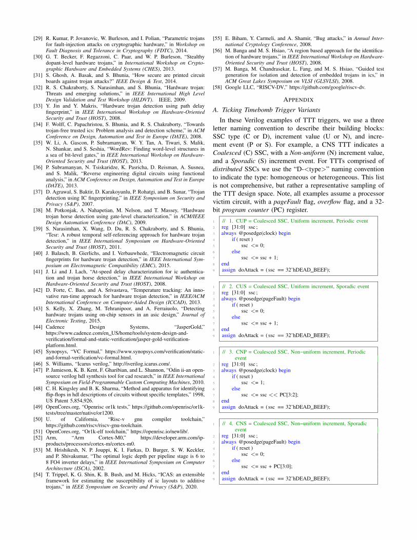
[29] R. Kumar, P. Jovanovic, W. Burleson, and I. Polian, “Parametric trojansfor fault-injection attacks on cryptographic hardware,” in Workshop onFault Diagnosis and Tolerance in Cryptography (FDTC), 2014.
[30] G. T. Becker, F. Regazzoni, C. Paar, and W. P. Burleson, “Stealthydopant-level hardware trojans,” in International Workshop on Crypto-graphic Hardware and Embedded Systems (CHES), 2013.
[31] S. Ghosh, A. Basak, and S. Bhunia, “How secure are printed circuitboards against trojan attacks?” IEEE Design & Test, 2014.
[32] R. S. Chakraborty, S. Narasimhan, and S. Bhunia, “Hardware trojan:Threats and emerging solutions,” in IEEE International High LevelDesign Validation and Test Workshop (HLDVT). IEEE, 2009.
[33] Y. Jin and Y. Makris, “Hardware trojan detection using path delayfingerprint,” in IEEE International Workshop on Hardware-OrientedSecurity and Trust (HOST), 2008.
[34] F. Wolff, C. Papachristou, S. Bhunia, and R. S. Chakraborty, “Towardstrojan-free trusted ics: Problem analysis and detection scheme,” in ACMConference on Design, Automation and Test in Europe (DATE), 2008.
[35] W. Li, A. Gascon, P. Subramanyan, W. Y. Tan, A. Tiwari, S. Malik,N. Shankar, and S. Seshia, “WordRev: Finding word-level structures ina sea of bit-level gates,” in IEEE International Workshop on Hardware-Oriented Security and Trust (HOST), 2013.
[36] P. Subramanyan, N. Tsiskaridze, K. Pasricha, D. Reisman, A. Susnea,and S. Malik, “Reverse engineering digital circuits using functionalanalysis,” in ACM Conference on Design, Automation and Test in Europe(DATE), 2013.
[37] D. Agrawal, S. Baktir, D. Karakoyunlu, P. Rohatgi, and B. Sunar, “Trojandetection using IC fingerprinting,” in IEEE Symposium on Security andPrivacy (S&P), 2007.
[38] M. Potkonjak, A. Nahapetian, M. Nelson, and T. Massey, “Hardwaretrojan horse detection using gate-level characterization,” in ACM/IEEEDesign Automation Conference (DAC), 2009.
[39] S. Narasimhan, X. Wang, D. Du, R. S. Chakraborty, and S. Bhunia,“Tesr: A robust temporal self-referencing approach for hardware trojandetection,” in IEEE International Symposium on Hardware-OrientedSecurity and Trust (HOST), 2011.
[40] J. Balasch, B. Gierlichs, and I. Verbauwhede, “Electromagnetic circuitfingerprints for hardware trojan detection,” in IEEE International Sym-posium on Electromagnetic Compatibility (EMC), 2015.
[41] J. Li and J. Lach, “At-speed delay characterization for ic authentica-tion and trojan horse detection,” in IEEE International Workshop onHardware-Oriented Security and Trust (HOST), 2008.
[42] D. Forte, C. Bao, and A. Srivastava, “Temperature tracking: An inno-vative run-time approach for hardware trojan detection,” in IEEE/ACMInternational Conference on Computer-Aided Design (ICCAD), 2013.
[43] S. Kelly, X. Zhang, M. Tehranipoor, and A. Ferraiuolo, “Detectinghardware trojans using on-chip sensors in an asic design,” Journal ofElectronic Testing, 2015.
[44] Cadence Design Systems, “JasperGold,”https://www.cadence.com/en US/home/tools/system-design-and-verification/formal-and-static-verification/jasper-gold-verification-platform.html.
[45] Synopsys, “VC Formal,” https://www.synopsys.com/verification/static-and-formal-verification/vc-formal.html.
[46] S. Williams, “Icarus verilog,” http://iverilog.icarus.com/.[47] P. Jamieson, K. B. Kent, F. Gharibian, and L. Shannon, “Odin ii-an open-
source verilog hdl synthesis tool for cad research,” in IEEE InternationalSymposium on Field-Programmable Custom Computing Machines, 2010.
[48] C. H. Kingsley and B. K. Sharma, “Method and apparatus for identifyingflip-flops in hdl descriptions of circuits without specific templates,” 1998,US Patent 5,854,926.
[49] OpenCores.org, “Openrisc or1k tests,” https://github.com/openrisc/or1k-tests/tree/master/native/or1200.
[50] U. of California, “Risc-v gnu compiler toolchain,”https://github.com/riscv/riscv-gnu-toolchain.
[51] OpenCores.org, “Or1k-elf toolchain,” https://openrisc.io/newlib/.[52] Arm, “Arm Cortex-M0,” https://developer.arm.com/ip-
products/processors/cortex-m/cortex-m0.[53] M. Hrishikesh, N. P. Jouppi, K. I. Farkas, D. Burger, S. W. Keckler,
and P. Shivakumar, “The optimal logic depth per pipeline stage is 6 to8 FO4 inverter delays,” in IEEE International Symposium on ComputerArchitecture (ISCA), 2002.
[54] T. Trippel, K. G. Shin, K. B. Bush, and M. Hicks, “ICAS: an extensibleframework for estimating the susceptibility of ic layouts to additivetrojans,” in IEEE Symposium on Security and Privacy (S&P), 2020.
[55] E. Biham, Y. Carmeli, and A. Shamir, “Bug attacks,” in Annual Inter-national Cryptology Conference, 2008.
[56] M. Banga and M. S. Hsiao, “A region based approach for the identifica-tion of hardware trojans,” in IEEE International Workshop on Hardware-Oriented Security and Trust (HOST), 2008.
[57] M. Banga, M. Chandrasekar, L. Fang, and M. S. Hsiao, “Guided testgeneration for isolation and detection of embedded trojans in ics,” inACM Great Lakes Symposium on VLSI (GLSVLSI), 2008.
[58] Google LLC, “RISCV-DV,” https://github.com/google/riscv-dv.
APPENDIX
A. Ticking Timebomb Trigger Variants
In these Verilog examples of TTT triggers, we use a threeletter naming convention to describe their building blocks:SSC type (C or D), increment value (U or N), and incre-ment event (P or S). For example, a CNS TTT indicates aCoalesced (C) SSC, with a Non-uniform (N) increment value,and a Sporadic (S) increment event. For TTTs comprised ofdistributed SSCs we use the “D-<type>” naming conventionto indicate the type: homogeneous or heterogeneous. This listis not comprehensive, but rather a representative sampling ofthe TTT design space. Note, all examples assume a processorvictim circuit, with a pageFault flag, overflow flag, and a 32-bit program counter (PC) register.
1 // 1. CUP = Coalesced SSC, Uniform increment, Periodic event2 reg [31:0] ssc ;3 always @posedge(clock) begin4 if ( reset )5 ssc <= 0;6 else7 ssc <= ssc + 1;8 end9 assign doAttack = (ssc == 32’hDEAD BEEF);
1 // 2. CUS = Coalesced SSC, Uniform increment, Sporadic event2 reg [31:0] ssc ;3 always @posedge(pageFault) begin4 if ( reset )5 ssc <= 0;6 else7 ssc <= ssc + 1;8 end9 assign doAttack = (ssc == 32’hDEAD BEEF);
1 // 3. CNP = Coalesced SSC, Non−uniform increment, Periodicevent
2 reg [31:0] ssc ;3 always @posedge(clock) begin4 if ( reset )5 ssc <= 1;6 else7 ssc <= ssc << PC[3:2];8 end9 assign doAttack = (ssc == 32’hDEAD BEEF);
1 // 4. CNS = Coalesced SSC, Non−uniform increment, Sporadicevent
2 reg [31:0] ssc ;3 always @posedge(pageFault) begin4 if ( reset )5 ssc <= 0;6 else7 ssc <= ssc + PC[3:0];8 end9 assign doAttack = (ssc == 32’hDEAD BEEF);

1 // 5. D−Homogeneous = Distributed SSC, same sub−components2 wire [31:0] ssc wire ;3 reg [15:0] lower half ssc ;4 reg [15:0] upper half ssc ;5 assign ssc wire = {upper half ssc , lower half ssc };6
7 // Two CUP sub−counters8 always @posedge(clock) begin9 if ( reset ) begin
10 lower half ssc <= 0;11 upper half ssc <= 0;12 end13 else begin14 lower half ssc <= lower half ssc + 1;15 upper half ssc <= upper half ssc + 1;16 end17 end18 assign doAttack = (ssc wire == 32’hDEAD BEEF);
1 // 6. D−Heterogeneous = Distributed SSC, differentsub−components
2 wire [31:0] ssc wire ;3 reg [15:0] lower half ssc ;4 reg [15:0] upper half ssc ;5 assign ssc wire = {upper half ssc , lower half ssc };6
7 // CUS sub−counter8 always @posedge(pageFault) begin9 if ( reset )
10 lower half ssc <= 0;11 else12 lower half ssc <= lower half ssc + 1;13 end14
15 // CNP sub−counter16 always @posedge(clock) begin17 if ( reset )18 upper half ssc <= 0;19 else20 upper half ssc <= upper half ssc + PC[3:0];21 end22 assign doAttack = (ssc wire == 32’hDEAD BEEF);
B. Constrained Randomized Verification
Given the size and complexity of modern hardware designs,verification engineers typically use randomly-generated testvectors to maximize verification coverage. Similarly, for twoof the four designs we study (AES and UART), we use LFSRsto generate random data-path inputs for test vectors. Thus, weask the question: does contrained random verification degradeBomberman’s performance? To demonstrate Bomberman istest-case agnostic, we generate 25 random test sequences forboth the AES and UART designs by randomly seeding theLFSR(s) in each design’s respective test bench (Fig. 6). Note,we do not experiment with constrained random verificationof the RISC-V and OR1200 designs as these require randominstruction stream generators, for which (to the best of ourknowledge) none exist in the open-source community thatare compatible with open-source RTL simulators like IVL orVerilator.7
For the AES design, we generate 25 random sequences ofseventy-five 128-bit keys and plaintexts. For the UART design,
7Google’s RISCV-DV open-source random instruction stream generator isnot compatible with either IVL or Verilator [58].
Distributed SSCs
Coalesced SSCs
Distributed SSCs
Coalesced SSCs
A) AES
B) UART
Fig. 10. Randomized Testing. Randomly generated verification test vectorsdo not affect Bomberman’s performance. Rather, Bomberman’s performanceis dependent on verification coverage with respect to SSC Properties 1 & 2(§IV-A) that define the behavior of a TTT. Namely, tests that cause more SSCsto cycle through all possible values, or repeat a value, reduce false positives.
we generate 25 random sequences of 16 bytes (to TX/RX).Similar to the false positive experiments (§VI-B), each testsequence for each design was repeated twice, without a systemreset in between. Given Bomberman’s inability to producefalse negatives, we only study the effects of randomnesson Bomberman’s false positive rate. Thus, unlike the falsepositive experiments, no TTT variants were implanted in eitherdesign. In Fig. 10, we plot the suspicious SSC traces producedby Bomberman across all randomly generated test vectors.Across both designs, zero suspicious SSCs (false positives) areobserved at the end of all 25 simulations, and each simulationtrace is nearly identical. Thus, Bomberman’s performance isnot test-case specific, rather, it is dependent on verificationcoverage, with respect to TTT invariants,8 i.e. Properties 1 &2 in §IV-A.
C. Example Hardware Data Flow Graph
An example hardware DFG generated by Bomberman’s SSCIdentification phase is shown below in Fig. 11.
8Verification coverage with respect to TTT invariants, is not to be confusedwith generic verification coverage such as functional, statement, condition,toggle, branch, and Finite State Machine (FSM) coverage. The former entailsexercising SSCs such that they violate TTT invariants (Properties 1–2 in§IV-A).
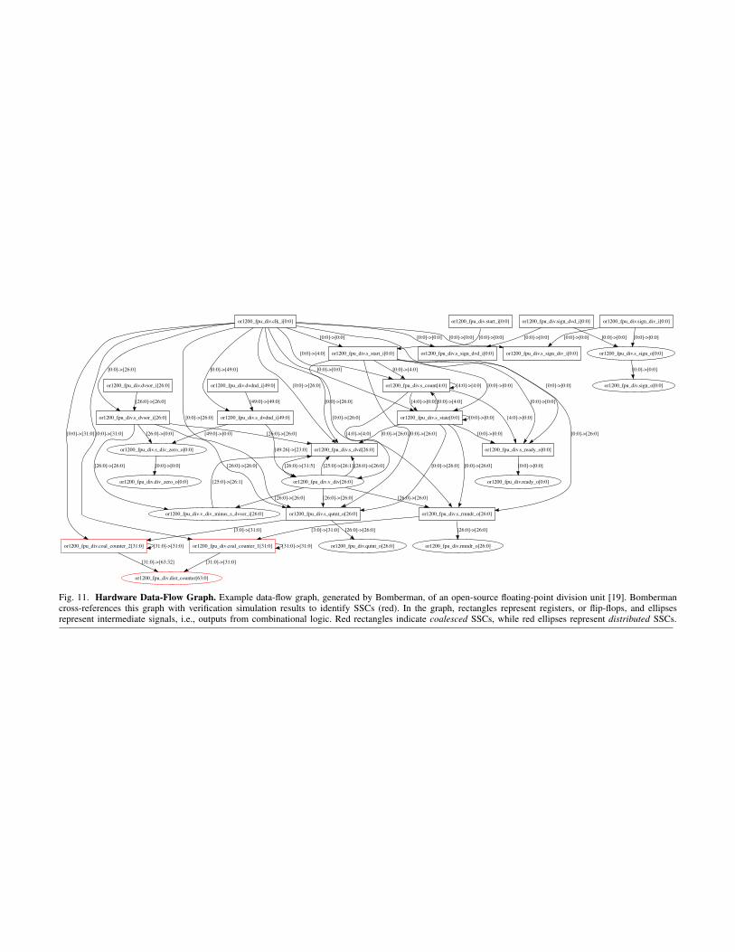
or1200_fpu_div.coal_counter_1[31:0] [31:0]->[31:0]
or1200_fpu_div.dist_counter[63:0]
[31:0]->[31:0]
or1200_fpu_div.coal_counter_2[31:0]
[31:0]->[63:32]
[31:0]->[31:0]
or1200_fpu_div.s_div_zero_o[0:0]
or1200_fpu_div.div_zero_o[0:0]
[0:0]->[0:0]
or1200_fpu_div.s_qutnt_o[26:0]
[3:0]->[31:0]
or1200_fpu_div.qutnt_o[26:0]
[26:0]->[26:0]
or1200_fpu_div.s_ready_o[0:0]
or1200_fpu_div.ready_o[0:0]
[0:0]->[0:0]
or1200_fpu_div.s_rmndr_o[26:0]
[3:0]->[31:0]
or1200_fpu_div.rmndr_o[26:0]
[26:0]->[26:0]
or1200_fpu_div.s_dvsor_i[26:0]
[26:0]->[0:0]
[26:0]->[26:0]
or1200_fpu_div.s_dvd[26:0]
[26:0]->[26:0]
or1200_fpu_div.v_div_minus_s_dvsor_i[26:0]
[26:0]->[26:0]
or1200_fpu_div.s_dvdnd_i[49:0]
[49:0]->[0:0]
or1200_fpu_div.v_div[26:0]
[49:26]->[23:0]
or1200_fpu_div.sign_dvd_i[0:0]
or1200_fpu_div.s_sign_o[0:0]
[0:0]->[0:0]
or1200_fpu_div.s_sign_dvd_i[0:0]
[0:0]->[0:0]
or1200_fpu_div.sign_o[0:0]
[0:0]->[0:0]
or1200_fpu_div.sign_div_i[0:0]
[0:0]->[0:0]
or1200_fpu_div.s_sign_div_i[0:0]
[0:0]->[0:0]
or1200_fpu_div.s_count[4:0]
[4:0]->[0:0]
[4:0]->[4:0]
[4:0]->[4:0]
or1200_fpu_div.s_state[0:0]
[4:0]->[0:0]
[26:0]->[26:0] [26:0]->[26:0]
[25:0]->[26:1] [26:0]->[26:0]
[26:0]->[26:0]
[26:0]->[31:5]
[25:0]->[26:1]
or1200_fpu_div.clk_i[0:0]
[0:0]->[31:0][0:0]->[31:0]
[0:0]->[26:0]
[0:0]->[0:0]
[0:0]->[26:0]
[0:0]->[26:0] [0:0]->[49:0]
[0:0]->[4:0]
[0:0]->[26:0]
[0:0]->[0:0] [0:0]->[0:0]
or1200_fpu_div.s_start_i[0:0]
[0:0]->[0:0]
[0:0]->[0:0]
or1200_fpu_div.dvdnd_i[49:0]
[49:0]->[49:0]
or1200_fpu_div.dvsor_i[26:0]
[26:0]->[26:0]
or1200_fpu_div.start_i[0:0]
[0:0]->[0:0]
[0:0]->[26:0]
[0:0]->[0:0]
[0:0]->[26:0]
[0:0]->[4:0]
[0:0]->[26:0]
[0:0]->[0:0]
[0:0]->[26:0]
[0:0]->[0:0]
[0:0]->[26:0]
[0:0]->[4:0]
[0:0]->[26:0]
[0:0]->[0:0]
Fig. 11. Hardware Data-Flow Graph. Example data-flow graph, generated by Bomberman, of an open-source floating-point division unit [19]. Bombermancross-references this graph with verification simulation results to identify SSCs (red). In the graph, rectangles represent registers, or flip-flops, and ellipsesrepresent intermediate signals, i.e., outputs from combinational logic. Red rectangles indicate coalesced SSCs, while red ellipses represent distributed SSCs.