Embed Size (px)
Citation preview

MEDIFUSIONR
MP-1000 SERVICE MANUAL
Daiwha Corp., Ltd.
Copyright 2002, DAIWHA Corporation, Ltd. All rights reserved.
This Manual describes the usage of an infusion pump(model : MP-1000) manufactured by Daiwha Corp., Ltd.
Only the person who is authorized by the company can repair this equipment and change a circuit. The equipment that is dismantled or repaired without prior permission cannot receive a post-management service. Parts and circuits used in this equipment can be changed for better performance
and safety reasons. After reading this manual, put it in a place with easy access so that everybody can
use it. If you have any questions or concerns regarding this equipment and user manual,
feel free to contact the company at the number below.
Address:
Daiwha Corp., Ltd., 733-18 Daiwha Bldg Yeoksam-dong Kangnam-Ku Seoul, Korea TEL: (822) 558 - 1711~6 FAX: (822) 554 - 0317
Safety precautions are divided into the following categories depending on the level of the expected hazard and damage caused by the inappropriate use of the product and the level of urgency that requires actions.
-DANGER: If you do not follow the instruction, it will cause severe injuries or even
death. - WARNING: If you do not follow the instruction, it can cause serious injuries or death.
- CAUTION: If you do not follow the instruction, it can cause minor injuries or damage
on the product.
TABLE OF CONTENTS
1. PRECAUTIONS
2. GENERAL DESCRIPTION
3. PARTS DESCRIPTION
4. CHECKOUT
5. THEORY OF OPERATION
6. TROUBLE SHOOTING
7. DISASSEMBLY AND REASSEMBLY
8. PARTS BREAKDOWN
9. PCB
10. SCHEMATIC
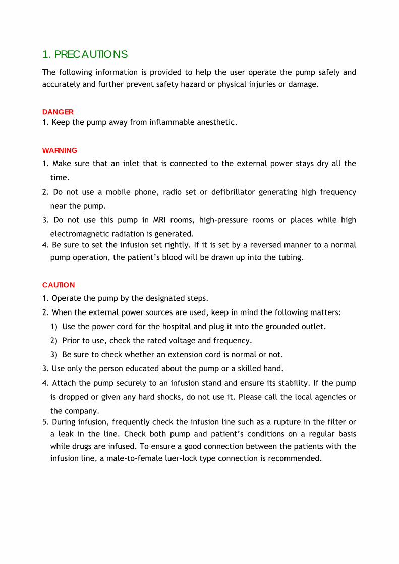
1. PRECAUTIONS The following information is provided to help the user operate the pump safely and accurately and further prevent safety hazard or physical injuries or damage.
DANGER 1. Keep the pump away from inflammable anesthetic.
WARNING
1. Make sure that an inlet that is connected to the external power stays dry all the
time.
2. Do not use a mobile phone, radio set or defibrillator generating high frequency
near the pump.
3. Do not use this pump in MRI rooms, high-pressure rooms or places while high
electromagnetic radiation is generated. 4. Be sure to set the infusion set rightly. If it is set by a reversed manner to a normal
pump operation, the patient’s blood will be drawn up into the tubing.
CAUTION
1. Operate the pump by the designated steps.
2. When the external power sources are used, keep in mind the following matters:
1) Use the power cord for the hospital and plug it into the grounded outlet.
2) Prior to use, check the rated voltage and frequency.
3) Be sure to check whether an extension cord is normal or not.
3. Use only the person educated about the pump or a skilled hand.
4. Attach the pump securely to an infusion stand and ensure its stability. If the pump
is dropped or given any hard shocks, do not use it. Please call the local agencies or
the company. 5. During infusion, frequently check the infusion line such as a rupture in the filter or
a leak in the line. Check both pump and patient’s conditions on a regular basis while drugs are infused. To ensure a good connection between the patients with the infusion line, a male-to-female luer-lock type connection is recommended.
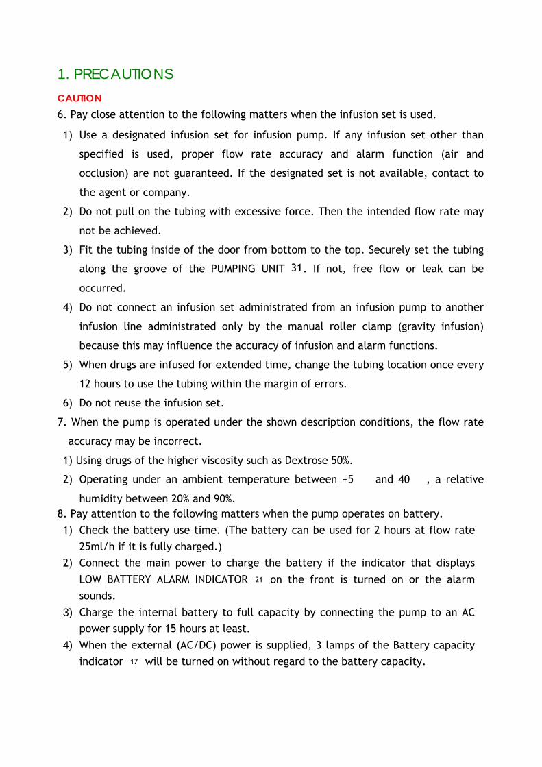
1. PRECAUTIONS CAUTION 6. Pay close attention to the following matters when the infusion set is used.
1) Use a designated infusion set for infusion pump. If any infusion set other than
specified is used, proper flow rate accuracy and alarm function (air and
occlusion) are not guaranteed. If the designated set is not available, contact to
the agent or company.
2) Do not pull on the tubing with excessive force. Then the intended flow rate may
not be achieved.
3) Fit the tubing inside of the door from bottom to the top. Securely set the tubing
along the groove of the PUMPING UNIT 31. If not, free flow or leak can be
occurred.
4) Do not connect an infusion set administrated from an infusion pump to another
infusion line administrated only by the manual roller clamp (gravity infusion)
because this may influence the accuracy of infusion and alarm functions.
5) When drugs are infused for extended time, change the tubing location once every
12 hours to use the tubing within the margin of errors.
6) Do not reuse the infusion set.
7. When the pump is operated under the shown description conditions, the flow rate
accuracy may be incorrect.
1) Using drugs of the higher viscosity such as Dextrose 50%.
2) Operating under an ambient temperature between +5 and 40 , a relative
humidity between 20% and 90%. 8. Pay attention to the following matters when the pump operates on battery. 1) Check the battery use time. (The battery can be used for 2 hours at flow rate
25ml/h if it is fully charged.) 2) Connect the main power to charge the battery if the indicator that displays
LOW BATTERY ALARM INDICATOR 21 on the front is turned on or the alarm sounds.
3) Charge the internal battery to full capacity by connecting the pump to an AC power supply for 15 hours at least.
4) When the external (AC/DC) power is supplied, 3 lamps of the Battery capacity indicator 17 will be turned on without regard to the battery capacity.

1. PRECAUTIONS CAUTION
9. Never connect both AC and DC power sources to the infusion pump at the same time. To use the DC power, be sure to check the polarity of the DC jack.
10. Do not sterilize the pump with autoclave or E.O. gas. Do not wipe the pump with thinner, solvent, benzene, ammonia, acetone, etc. Use a wet cloth to clean.
11. Do not dismantle the pump.
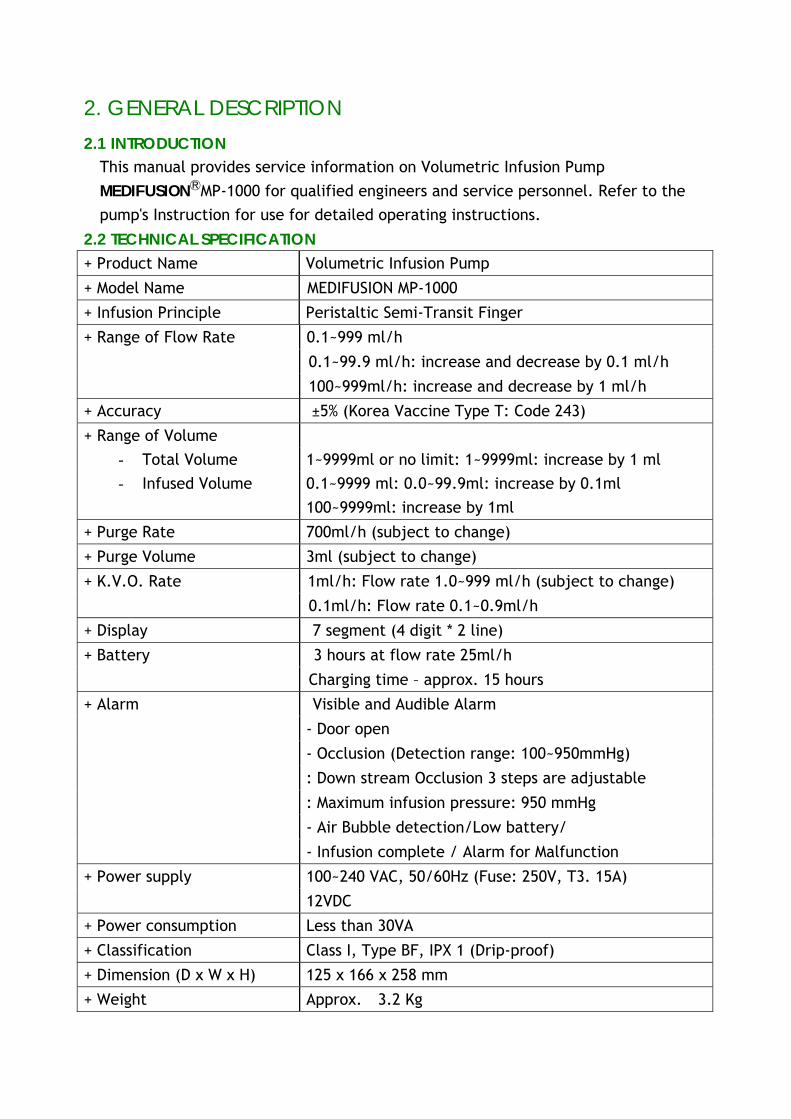
2. GENERAL DESCRIPTION 2.1 INTRODUCTION
This manual provides service information on Volumetric Infusion Pump MEDIFUSIONMP-1000 for qualified engineers and service personnel. Refer to the pump's Instruction for use for detailed operating instructions.
2.2 TECHNICAL SPECIFICATION
+ Product Name Volumetric Infusion Pump
+ Model Name MEDIFUSION MP-1000
+ Infusion Principle Peristaltic Semi-Transit Finger
0.1~999 ml/h
0.1~99.9 ml/h: increase and decrease by 0.1 ml/h
+ Range of Flow Rate
100~999ml/h: increase and decrease by 1 ml/h
+ Accuracy ±5% (Korea Vaccine Type T: Code 243)
+ Range of Volume - Total Volume 1~9999ml or no limit: 1~9999ml: increase by 1 ml - Infused Volume 0.1~9999 ml: 0.0~99.9ml: increase by 0.1ml
100~9999ml: increase by 1ml
+ Purge Rate 700ml/h (subject to change)
+ Purge Volume 3ml (subject to change)
1ml/h: Flow rate 1.0~999 ml/h (subject to change) + K.V.O. Rate
0.1ml/h: Flow rate 0.1~0.9ml/h
+ Display 7 segment (4 digit * 2 line)
3 hours at flow rate 25ml/h + Battery
Charging time – approx. 15 hours
Visible and Audible Alarm
- Door open
- Occlusion (Detection range: 100~950mmHg)
: Down stream Occlusion 3 steps are adjustable
: Maximum infusion pressure: 950 mmHg
- Air Bubble detection/Low battery/
+ Alarm
- Infusion complete / Alarm for Malfunction
100~240 VAC, 50/60Hz (Fuse: 250V, T3. 15A) + Power supply
12VDC
+ Power consumption Less than 30VA
+ Classification Class I, Type BF, IPX 1 (Drip-proof)
+ Dimension (D x W x H) 125 x 166 x 258 mm
+ Weight Approx. 3.2 Kg
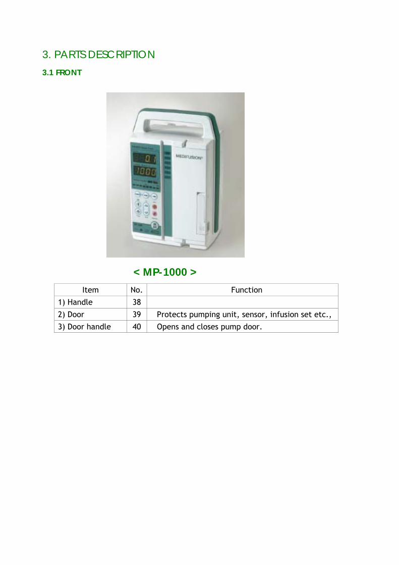
3. PARTS DESCRIPTION 3.1 FRONT
< MP-1000 >
Item No. Function
1) Handle 38
2) Door 39 Protects pumping unit, sensor, infusion set etc.,
3) Door handle 40 Opens and closes pump door.
3. PARTS DESCRIPTION 3.2 KEY
ITEM NO FUNCTION
1) F. RATE KEY 11 This key is used to set up the flow rate.
2) T.VOL KEY 9 This key is used to set up the total volume.
3) I.VOL KEY 10 This key is used to view the infused volume.
4) UP KEY 34 This key is used to set up the flow rate or total volume. The number increases by one inch each time when the key is pressed. The number rapidly increases while the key is being held down.
5) DOWN KEY 35 This key is used to set up the flow rate or total volume. The number decreases by one inch each time when the key is pressed. The number rapidly decreases while the key is being held down.
6) SHIFT KEY 12 This key is used to set up the flow rate or total volume. When this key is pressed, the digit shifts to the left.
7) PURGE KEY 8 This key is used for purge. The total purge volume will be infused automatically at the set up purge flow rate each time the key is pressed. (Note: It does not sense air and occlusion.)
8) START KEY 13 This key is used to start the infusion.
9) STOP/CLEAR KEY 14 This key is used to stop infusion. In addition, when the key is pressed for two seconds while setting up the total volume and flow rate (including the infused volume), the set data will be cleared off.
10) ON/OFF KEY 15 This key is used to turn the pump on/off. Press the key for two or three seconds to turn the pump on/off. If external power is supplied, the battery will be charged even if the corresponding indicator is off.
3. PARTS DESCRIPTION 3.2 KEY
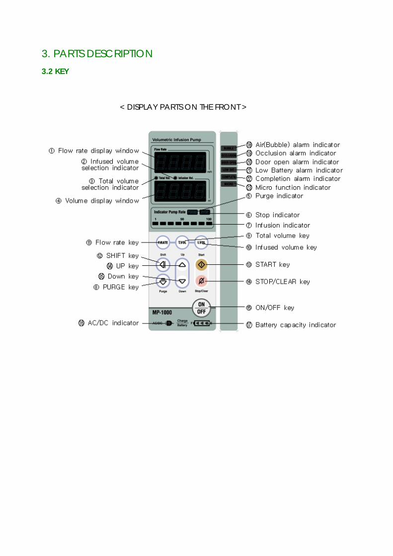
< DISPLAY PARTS ON THE FRONT >
3. PARTS DESCRIPTION
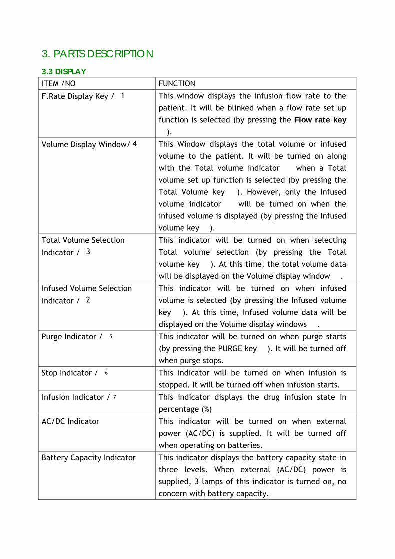
3.3 DISPLAY ITEM /NO FUNCTION
F.Rate Display Key / 1 This window displays the infusion flow rate to the patient. It will be blinked when a flow rate set up function is selected (by pressing the Flow rate key ⑪).
Volume Display Window/4 This Window displays the total volume or infused volume to the patient. It will be turned on along with the Total volume indicator when a Total ③
volume set up function is selected (by pressing the Total Volume key ). However, only the Infused ⑨
volume indicator will be turned on when the ②
infused volume is displayed (by pressing the Infused volume key ). ⑩
Total Volume Selection
Indicator / 3
This indicator will be turned on when selecting Total volume selection (by pressing the Total volume key ). At this time, the total volume data ⑨
will be displayed on the Volume display window . ④
Infused Volume Selection
Indicator / 2
This indicator will be turned on when infused volume is selected (by pressing the Infused volume key ). At this time, Infused volume data will be ⑩
displayed on the Volume display windows . ④
Purge Indicator / 5 This indicator will be turned on when purge starts (by pressing the PURGE key ). It will be turned off ⑧
when purge stops.
Stop Indicator / 6 This indicator will be turned on when infusion is stopped. It will be turned off when infusion starts.
Infusion Indicator /7 This indicator displays the drug infusion state in percentage (%)
AC/DC Indicator This indicator will be turned on when external power (AC/DC) is supplied. It will be turned off when operating on batteries.
Battery Capacity Indicator This indicator displays the battery capacity state in three levels. When external (AC/DC) power is supplied, 3 lamps of this indicator is turned on, no concern with battery capacity.
3. PARTS DESCRIPTION
3.3 DISPLAY ITEM / NO FUNCTION
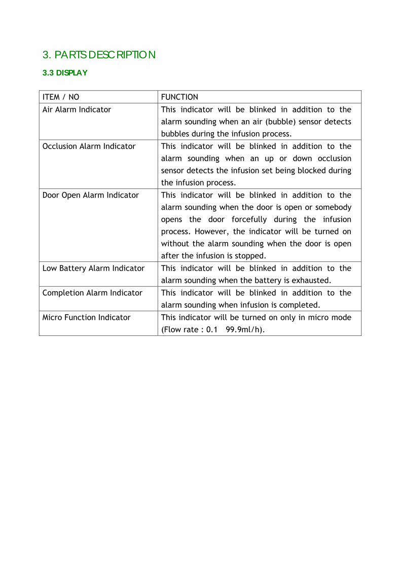
Air Alarm Indicator This indicator will be blinked in addition to the alarm sounding when an air (bubble) sensor detects bubbles during the infusion process.
Occlusion Alarm Indicator This indicator will be blinked in addition to the alarm sounding when an up or down occlusion sensor detects the infusion set being blocked during the infusion process.
Door Open Alarm Indicator This indicator will be blinked in addition to the alarm sounding when the door is open or somebody opens the door forcefully during the infusion process. However, the indicator will be turned on without the alarm sounding when the door is open after the infusion is stopped.
Low Battery Alarm Indicator This indicator will be blinked in addition to the alarm sounding when the battery is exhausted.
Completion Alarm Indicator This indicator will be blinked in addition to the alarm sounding when infusion is completed.
Micro Function Indicator This indicator will be turned on only in micro mode (Flow rate : 0.1˜99.9ml/h).
3. PARTS DESCRIPTION
3.4 REAR
Item No. Function
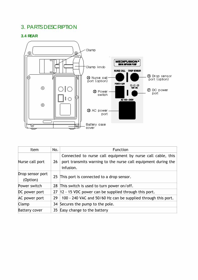
Nurse call port 26 Connected to nurse call equipment by nurse call cable, this port transmits warning to the nurse call equipment during the infusion.
Drop sensor port (Option)
25 This port is connected to a drop sensor.
Power switch 28 This switch is used to turn power on/off.
DC power port 27 12 - 15 VDC power can be supplied through this port.
AC power port 29 100 - 240 VAC and 50/60 Hz can be supplied through this port.
Clamp 34 Secures the pump to the pole.
Battery cover 35 Easy change to the battery
3. PARTS DESCRIPTION
3.5 DOOR INSIDE
Item No Function
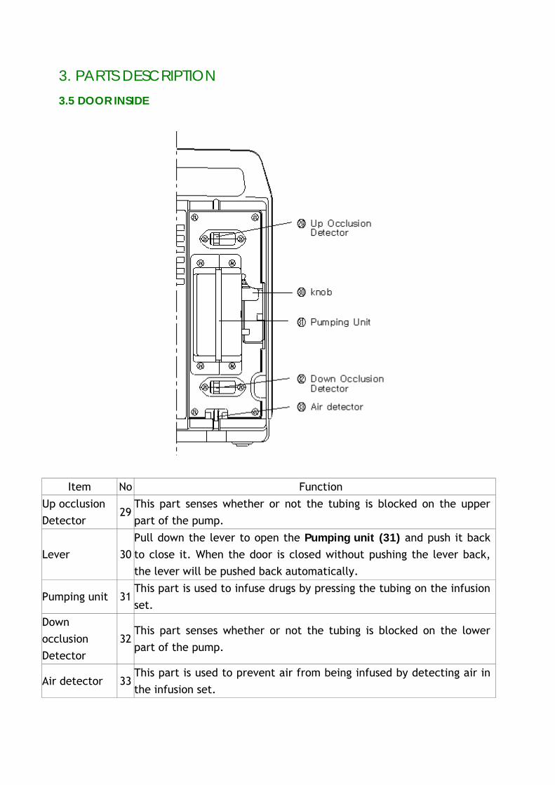
Up occlusion Detector
29 This part senses whether or not the tubing is blocked on the upper part of the pump.
Lever 30 Pull down the lever to open the Pumping unit (31) and push it back to close it. When the door is closed without pushing the lever back, the lever will be pushed back automatically.
Pumping unit 31 This part is used to infuse drugs by pressing the tubing on the infusion set.
Down occlusion Detector
32 This part senses whether or not the tubing is blocked on the lower part of the pump.
Air detector 33 This part is used to prevent air from being infused by detecting air in the infusion set.
4.CHECKOUT 4.1 CHECKOUT OF POWER
1) Connect the infusion pump to AC power. Unload the set into the pump and close the pump door at this time.
2) Verify that AC/DC indicator is on. 3) Turn the power switch on at the rear of the pump. 4) Verify that all of the battery capacity indicators in the front of the pump are on. 5) Verify that AC/DC indicator is off, When the pump disconnect with AC power. And
verify that the battery capacity indicator in the front of the pump is on. 6) Connect the infusion pump to AC power again and Verify that AC/DC indicator is
on.
4.2 SELF TEST
1) Press the on/off key at the front of the pump for 2 seconds and check that the pump performs the following self test.
2) The following displays illuminate momentarily; Alarm indicators, Infusion indicators. Total volume indicator and infused volume indicator, purge indicator, stop
indicator and battery capacity indicator 3) All segments of the flow rate display window and volume display window
illuminate momentarily. 4) Press the on/off key at the front of the pump for 2 seconds and verify that display
turn off.
4.3 ACCURACY TEST
1) Turn the pump on and load an infusion set without air in the tubing 2) Program a flow rate of 100 ml/h and a total volume of 100 ml and verify that
infused volume is 0 ml. 3) Start infusion by pressing the START key. While the pump is running, check for the
normal operation without occlusion and that no bubbles are seen in the tubing. 4) When the pump has delivered the selected volume, the pump activates an audible alarm, illuminates the completion alarm LED, and switches to a KVO (Keep Vein Open) rate.
5) To stop the infusion, press the STOP key and verify infusion time and infused volume.
4.CHECKOUT
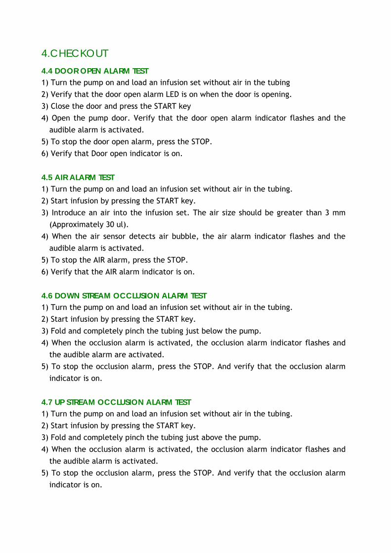
4.4 DOOR OPEN ALARM TEST
1) Turn the pump on and load an infusion set without air in the tubing 2) Verify that the door open alarm LED is on when the door is opening. 3) Close the door and press the START key 4) Open the pump door. Verify that the door open alarm indicator flashes and the
audible alarm is activated. 5) To stop the door open alarm, press the STOP. 6) Verify that Door open indicator is on.
4.5 AIR ALARM TEST
1) Turn the pump on and load an infusion set without air in the tubing. 2) Start infusion by pressing the START key. 3) Introduce an air into the infusion set. The air size should be greater than 3 mm
(Approximately 30 ul). 4) When the air sensor detects air bubble, the air alarm indicator flashes and the
audible alarm is activated. 5) To stop the AIR alarm, press the STOP. 6) Verify that the AIR alarm indicator is on.
4.6 DOWN STREAM OCCLUSION ALARM TEST
1) Turn the pump on and load an infusion set without air in the tubing. 2) Start infusion by pressing the START key. 3) Fold and completely pinch the tubing just below the pump. 4) When the occlusion alarm is activated, the occlusion alarm indicator flashes and
the audible alarm are activated. 5) To stop the occlusion alarm, press the STOP. And verify that the occlusion alarm
indicator is on.
4.7 UP STREAM OCCLUSION ALARM TEST
1) Turn the pump on and load an infusion set without air in the tubing. 2) Start infusion by pressing the START key. 3) Fold and completely pinch the tubing just above the pump. 4) When the occlusion alarm is activated, the occlusion alarm indicator flashes and
the audible alarm is activated. 5) To stop the occlusion alarm, press the STOP. And verify that the occlusion alarm
indicator is on.
4.CHECKOUT
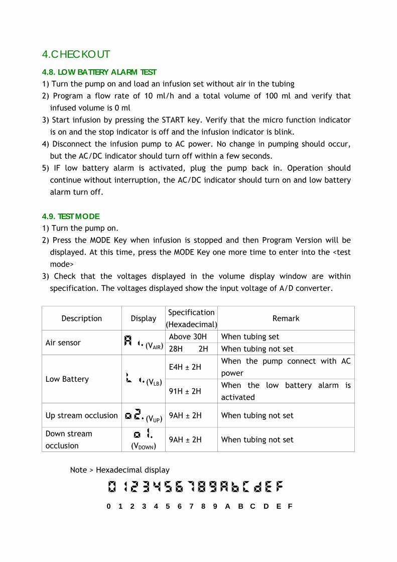
4.8. LOW BATTERY ALARM TEST
1) Turn the pump on and load an infusion set without air in the tubing 2) Program a flow rate of 10 ml/h and a total volume of 100 ml and verify that
infused volume is 0 ml 3) Start infusion by pressing the START key. Verify that the micro function indicator
is on and the stop indicator is off and the infusion indicator is blink. 4) Disconnect the infusion pump to AC power. No change in pumping should occur,
but the AC/DC indicator should turn off within a few seconds. 5) IF low battery alarm is activated, plug the pump back in. Operation should
continue without interruption, the AC/DC indicator should turn on and low battery alarm turn off.
4.9. TEST MODE
1) Turn the pump on. 2) Press the MODE Key when infusion is stopped and then Program Version will be
displayed. At this time, press the MODE Key one more time to enter into the <test mode>
3) Check that the voltages displayed in the volume display window are within specification. The voltages displayed show the input voltage of A/D converter.
Description Display Specification
(Hexadecimal)Remark
Above 30H When tubing set Air sensor (VAIR) 28H + 2H When tubing not set
E4H ± 2H When the pump connect with AC power
Low Battery (VLB) 91H ± 2H
When the low battery alarm is activated
Up stream occlusion (VUP) 9AH ± 2H When tubing not set
Down stream occlusion (VDOWN)
9AH ± 2H When tubing not set
Note > Hexadecimal display
0 1 2 3 4 5 6 7 8 9 A B C D E F
4.CHECKOUT
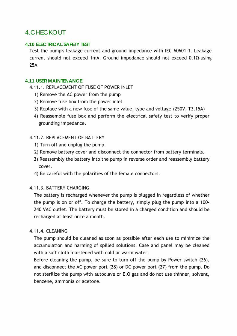
4.10 ELECTRICAL SAFETY TEST
Test the pump's leakage current and ground impedance with IEC 60601-1. Leakage current should not exceed 1mA. Ground impedance should not exceed 0.1Ω-using 25A
4.11 USER MAINTENANCE
4.11.1. REPLACEMENT OF FUSE OF POWER INLET 1) Remove the AC power from the pump 2) Remove fuse box from the power inlet 3) Replace with a new fuse of the same value, type and voltage.(250V, T3.15A) 4) Reassemble fuse box and perform the electrical safety test to verify proper
grounding impedance.
4.11.2. REPLACEMENT OF BATTERY 1) Turn off and unplug the pump. 2) Remove battery cover and disconnect the connector from battery terminals. 3) Reassembly the battery into the pump in reverse order and reassembly battery
cover. 4) Be careful with the polarities of the female connectors.
4.11.3. BATTERY CHARGING
The battery is recharged whenever the pump is plugged in regardless of whether the pump is on or off. To charge the battery, simply plug the pump into a 100-240 VAC outlet. The battery must be stored in a charged condition and should be recharged at least once a month.
4.11.4. CLEANING
The pump should be cleaned as soon as possible after each use to minimize the accumulation and harming of spilled solutions. Case and panel may be cleaned with a soft cloth moistened with cold or warm water. Before cleaning the pump, be sure to turn off the pump by Power switch (26), and disconnect the AC power port (28) or DC power port (27) from the pump. Do not sterilize the pump with autoclave or E.O gas and do not use thinner, solvent, benzene, ammonia or acetone.
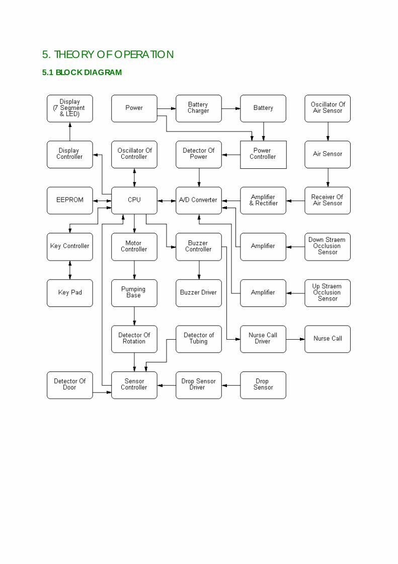
5. THEORY OF OPERATION 5.1 BLOCK DIAGRAM
5. THEORY OF OPERATION
5.2 POWER SUPPLY PART Power supply part consists of SMPS and 5V regulator, battery, and battery charger. The AC power inputs into inlet with EMC/EMI filter. SMPS converts from DC power. Whenever the SMPS is activated by AC power, the AC/DC indicator on the front is lit. SMPS (Switching Mode Power Supply) converts AC power (100~240VAC, 50/60Hz) into DC power (15VDC, 2.3A). The SMPS has over-voltage and over-current protection. Two 3.15A slow blow replacement fuses are required for AC. Battery charger will charge the battery as long as the pump is connected to a specified AC power. 5V regulator circuit on the main rear board generates 5V(Vcc) for electronic components from the output of SMPS and internal battery.
5.3 CPU PART
CPU part consists of controller (CPU) and EPROM, EEPROM, address decoder and oscillator, reset circuit. The controller (CPU) controls all pump function and gather data from the key controller, A/D converter, EEPROM and alarm controller. The controller utilizes 16-address line and 8 data line. Program reserved at the EPROM make the system work and main data will be maintained at the serial EEPROM. Oscillator generates 12MHz clock and pulse divider generates a pulse for the A/D converter.
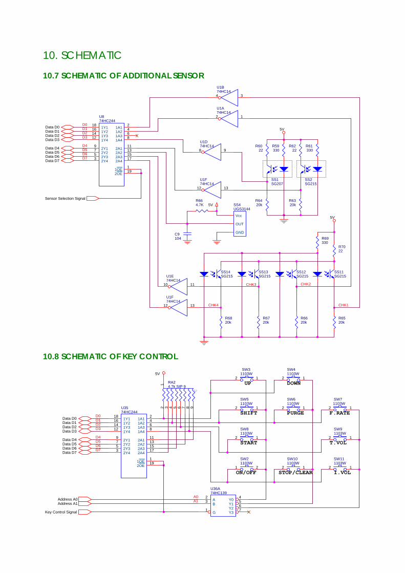
5.4 KEY CONTROL PART
Key control part consists of keypad and key controller. The key is multiplexed 4 x 4 array, which is scanned by key controller. One of 4 select lines determines which four keys are read. All normal key depressions are decoded by this matrix.
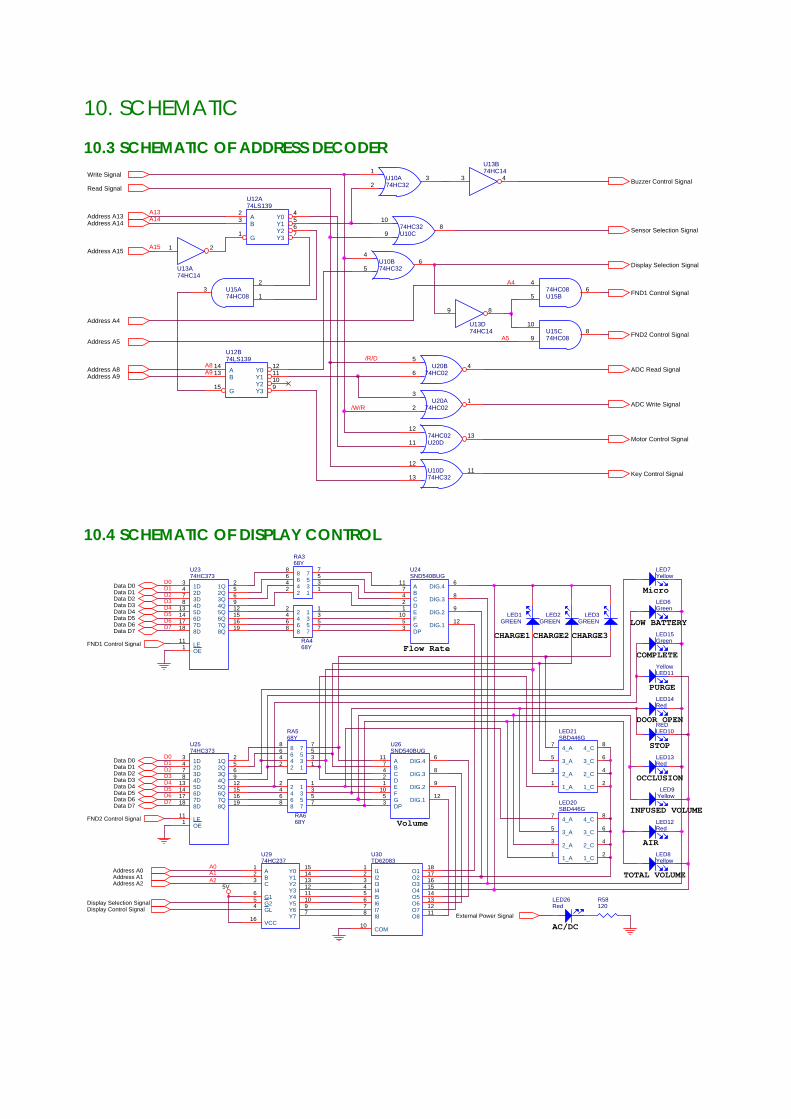
5.5 DISPLAY PART
Display part consists of display controller and two 7-segments with 4digits and several LED. Two-display controller manages display and displays are turned on in order. Alarm/operation indicators are managed by the controller, while AC/DC indicator is managed by its own circuit.
5. THEORY OF OPERATION
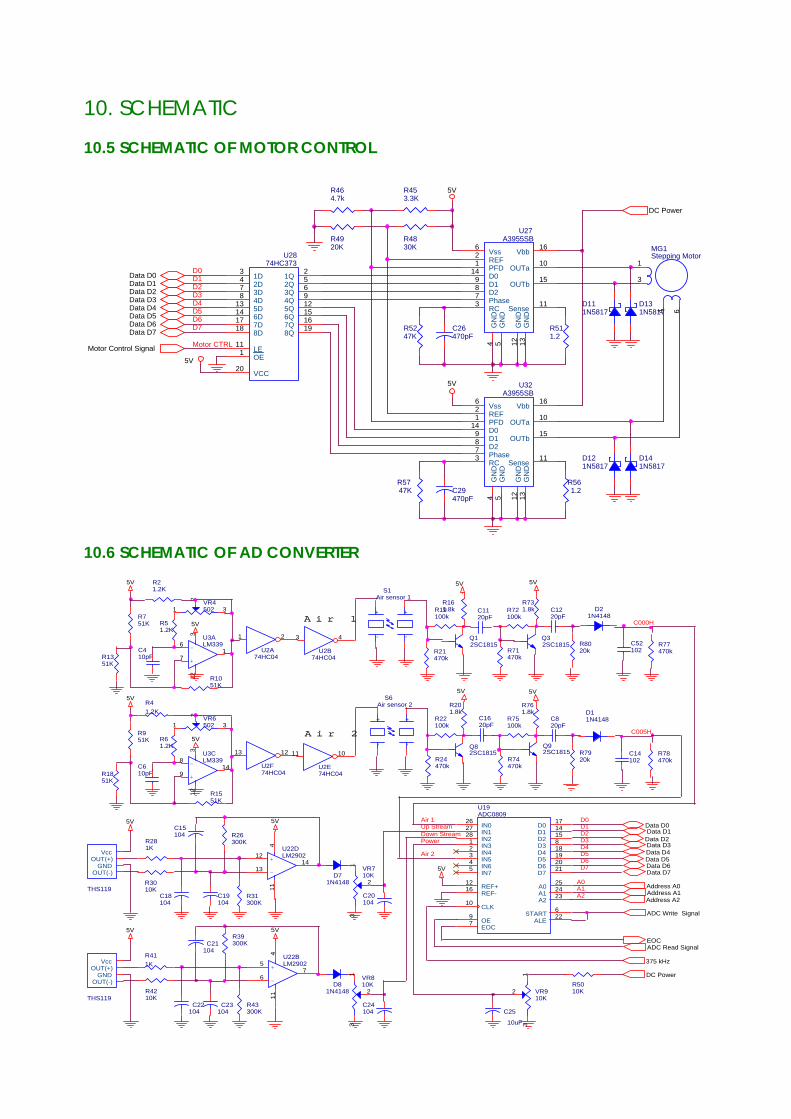
5.6 MOTOR CONTROL PART Motor control part consists of motor, motor driver and rotation detector. The motor adopts bi-polar stepping motor to precise control and is controlled by 1/8, 1/4, 1/2 micro step control in order to precise than control. The motor is shut down when an alarm or failure occurs. The motor speed range permits infusions from 1 to 999 ml/h. The motor rotation detector assures that pump drive rotation occurs or the motor shuts down. CPU reads the motor rotation signal via the sensor controller.
5.7 SENSOR
1) Air sensor part The air sensor part consists of an ultrasonic transmitter and receiver mounted on opposite sides of the tubing path. The transmitter consists of an oscillator and piezo ceramic that transform electric energy into mechanical energy. The transmitter consists of signal process part and piezo ceramic that transform mechanical energy into electric energy. The transducers operate on the principle that air in the tubing transmits ultrasonic energy much less effectively than fluid. This energy is amplified, rectified, applied to the A/D converter and than converted into a digital signal. The CPU monitors the signal and activates an AIR alarm if it detects the absence of a level energy.
2) Occlusion sensor part The down and up stream occlusion sensor consists of a moving magnet and hall sensor that detects magnet. As the condition of infusion set, up and down of magnet, which is tangled by the end of occlusion is sensed by hall sensor. The moving magnet is spring-loaded against the tubing, when pressure down stream of the pump increase, the magnet moves from its original position, which in turns change the voltage of the sensor. If the occlusion is sufficient to cause a specific voltage change, the CPU activates an alarm. There is a maximum expansion of the tubing beyond which the pump will no longer permit operation.
3) Low battery detector The input voltage is sensed by step-downed in use of resistance. The alarm works when the voltage goes down under base line. When the voltage goes below impracticable figure, the display and motor stop.
4) Door Open Sensor When the door is opened, the drop in voltage that is sensed by the distance between the magnet stuck to the door and hole sensor. After all, the alarm works.
6. TROUBLE SHOOTING
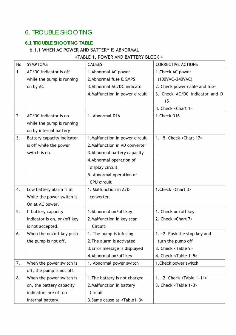
6.1 TROUBLE SHOOTING TABLE 6.1.1 WHEN AC POWER AND BATTERY IS ABNORMAL <TABLE 1. POWER AND BATTERY BLOCK >
No SYMPTOMS CAUSES CORRECTIVE ACTIONS
AC/DC indicator is off 1.Abnormal AC power 1.Check AC power
while the pump is running 2.Abnormal fuse & SMPS (100VAC~240VAC)
on by AC 3.Abnormal AC/DC indicator 2. Check power cable and fuse
4.Malfunction in power circuit 3. Check AC/DC indicator and D
15
1.
4. Check <Chart 1>
AC/DC indicator is on 1. Abnormal D16 1.Check D16
while the pump is running
2.
on by internal battery
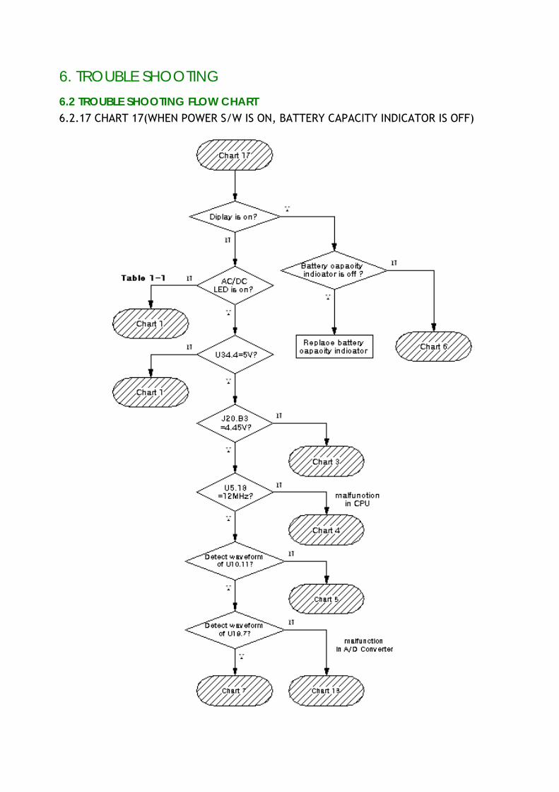
Battery capacity indicator 1.Malfunction in power circuit 1. ~5. Check <Chart 17>
is off while the power 2.Malfunction in AD converter
switch is on. 3.Abnormal battery capacity
4.Abnormal operation of
display circuit
5. Abnormal operation of
3.
CPU circuit
Low battery alarm is lit 1. Malfunction in A/D 1.Check <Chart 3>
While the power switch is converter.
4.
On at AC power.
If battery capacity 1.Abnormal on/off key 1. Check on/off key
indicator is on, on/off key 2.Malfunction in key scan 2. Check <Chart 7>
5.
is not accepted. Circuit.
When the on/off key push 1. The pump is infusing 1. ~2. Push the stop key and
the pump is not off. 2.The alarm is activated turn the pump off
3.Error message is displayed 3. Check <Table 9>
6.
4.Abnormal on/off key 4. Check <Table 1~5>
7. When the power switch is 1. Abnormal power switch 1.Check power switch
off, the pump is not off.
When the power switch is 1.The battery is not charged 1. ~2. Check <Table 1~11>
on, the battery capacity 2.Malfunction in battery 3. Check <Table 1~3>
indicators are off on Circuit
8.
internal battery. 3.Same cause as <Table1~3>
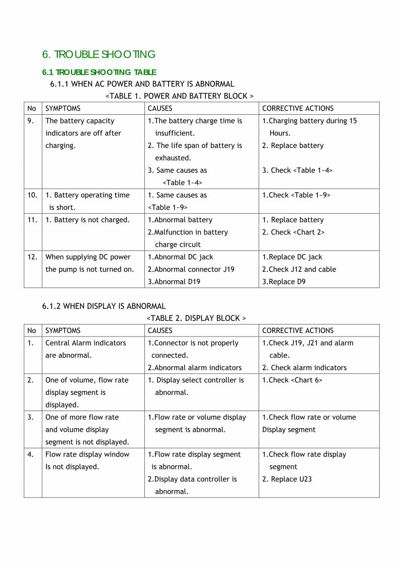
6. TROUBLE SHOOTING
6.1 TROUBLE SHOOTING TABLE 6.1.1 WHEN AC POWER AND BATTERY IS ABNORMAL
<TABLE 1. POWER AND BATTERY BLOCK > No SYMPTOMS CAUSES CORRECTIVE ACTIONS
The battery capacity 1.The battery charge time is 1.Charging battery during 15
indicators are off after insufficient. Hours.
charging. 2. The life span of battery is 2. Replace battery
exhausted.
3. Same causes as 3. Check <Table 1~4>
9.
<Table 1~4>
1. Battery operating time 1. Same causes as 1.Check <Table 1~9> 10.
is short. <Table 1~9>
1. Battery is not charged. 1.Abnormal battery 1. Replace battery
2.Malfunction in battery 2. Check <Chart 2>
11.
charge circuit
When supplying DC power 1.Abnormal DC jack 1.Replace DC jack
the pump is not turned on. 2.Abnormal connector J19 2.Check J12 and cable
12.
3.Abnormal D19 3.Replace D9
6.1.2 WHEN DISPLAY IS ABNORMAL <TABLE 2. DISPLAY BLOCK >
No SYMPTOMS CAUSES CORRECTIVE ACTIONS
Central Alarm indicators 1.Connector is not properly 1.Check J19, J21 and alarm
are abnormal. connected. cable.
1.
2.Abnormal alarm indicators 2. Check alarm indicators
One of volume, flow rate 1. Display select controller is 1.Check <Chart 6>
display segment is abnormal.
2.
displayed.
One of more flow rate 1.Flow rate or volume display 1.Check flow rate or volume
and volume display segment is abnormal. Display segment
3.
segment is not displayed.
Flow rate display window 1.Flow rate display segment 1.Check flow rate display
Is not displayed. is abnormal. segment
2.Display data controller is 2. Replace U23
4.
abnormal.
6. TROUBLE SHOOTING
6.1 TROUBLE SHOOTING TABLE 6.1.2 WHEN DISPLAY IS ABNORMAL
<TABLE 2. DISPLAY BLOCK >
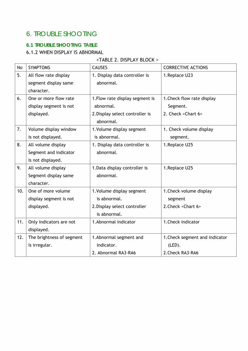
No SYMPTOMS CAUSES CORRECTIVE ACTIONS
All flow rate display 1. Display data controller is 1.Replace U23
segment display same abnormal.
5.
character.
One or more flow rate 1.Flow rate display segment is 1.Check flow rate display
display segment is not abnormal. Segment.
displayed. 2.Display select controller is 2. Check <Chart 6>
6.
abnormal.
Volume display window 1.Volume display segment 1. Check volume display 7.
is not displayed. is abnormal. segment.
All volume display 1. Display data controller is 1.Replace U25
Segment and indicator abnormal.
8.
Is not displayed.
All volume display 1.Data display controller is 1.Replace U25
Segment display same abnormal.
9.
character.
One of more volume 1.Volume display segment 1.Check volume display
display segment is not is abnormal. segment
displayed. 2.Display select controller 2.Check <Chart 6>
10.
is abnormal.
Only indicators are not 1.Abnormal indicator 1.Check indicator 11.
displayed.
The brightness of segment 1.Abnormal segment and 1.Check segment and indicator
Is irregular. indicator. (LED).
12.
2. Abnormal RA3-RA6 2.Check RA3-RA6
6. TROUBLE SHOOTING
6.1 TROUBLE SHOOTING TABLE 6.1.3 WHEN KEY IS ABNORMAL
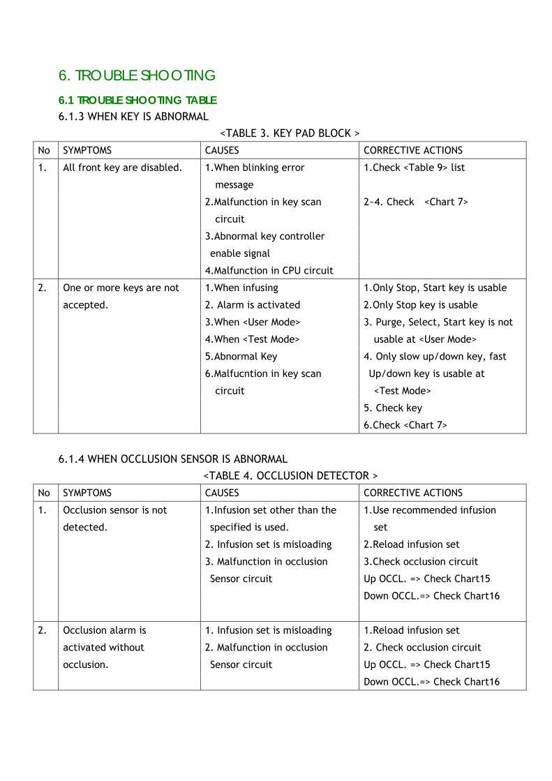
<TABLE 3. KEY PAD BLOCK > No SYMPTOMS CAUSES CORRECTIVE ACTIONS
All front key are disabled. 1.When blinking error 1.Check <Table 9> list
message
2.Malfunction in key scan 2~4. Check <Chart 7>
circuit
3.Abnormal key controller
enable signal
1.
4.Malfunction in CPU circuit
One or more keys are not 1.When infusing 1.Only Stop, Start key is usable
accepted. 2. Alarm is activated 2.Only Stop key is usable
3.When <User Mode> 3. Purge, Select, Start key is not
4.When <Test Mode> usable at <User Mode>
5.Abnormal Key 4. Only slow up/down key, fast
6.Malfucntion in key scan Up/down key is usable at
circuit <Test Mode>
5. Check key
2.
6.Check <Chart 7>
6.1.4 WHEN OCCLUSION SENSOR IS ABNORMAL <TABLE 4. OCCLUSION DETECTOR >
No SYMPTOMS CAUSES CORRECTIVE ACTIONS
Occlusion sensor is not 1.Infusion set other than the 1.Use recommended infusion
detected. specified is used. set
2. Infusion set is misloading 2.Reload infusion set
3. Malfunction in occlusion 3.Check occlusion circuit
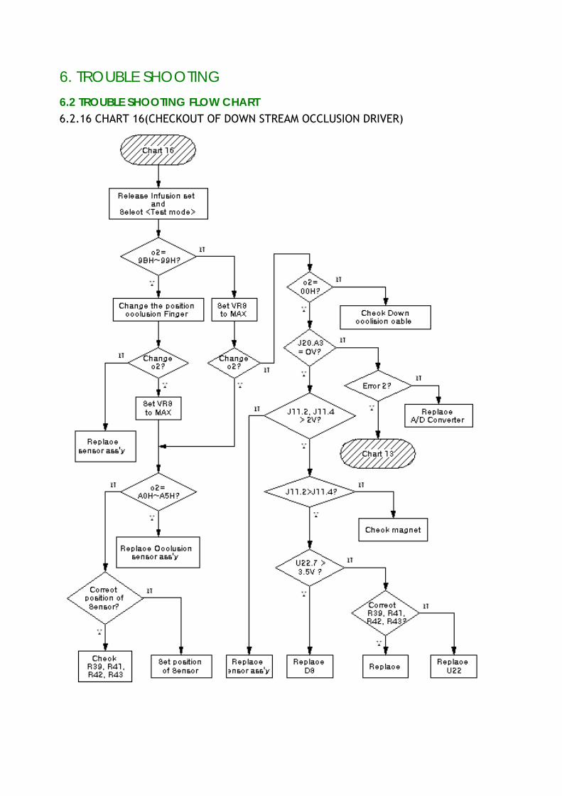
Sensor circuit Up OCCL. => Check Chart15
Down OCCL.=> Check Chart16
1.
Occlusion alarm is 1. Infusion set is misloading 1.Reload infusion set
activated without 2. Malfunction in occlusion 2. Check occlusion circuit
occlusion. Sensor circuit Up OCCL. => Check Chart15
2.
Down OCCL.=> Check Chart16
6. TROUBLE SHOOTING
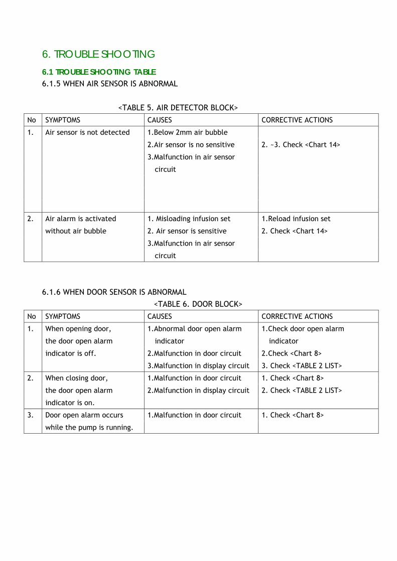
6.1 TROUBLE SHOOTING TABLE 6.1.5 WHEN AIR SENSOR IS ABNORMAL
<TABLE 5. AIR DETECTOR BLOCK> No SYMPTOMS CAUSES CORRECTIVE ACTIONS
Air sensor is not detected 1.Below 2mm air bubble
2.Air sensor is no sensitive 2. ~3. Check <Chart 14>
3.Malfunction in air sensor
circuit
1.
Air alarm is activated 1. Misloading infusion set 1.Reload infusion set
without air bubble 2. Air sensor is sensitive 2. Check <Chart 14>
3.Malfunction in air sensor
2.
circuit
6.1.6 WHEN DOOR SENSOR IS ABNORMAL
<TABLE 6. DOOR BLOCK> No SYMPTOMS CAUSES CORRECTIVE ACTIONS
When opening door, 1.Abnormal door open alarm 1.Check door open alarm
the door open alarm indicator indicator
indicator is off. 2.Malfunction in door circuit 2.Check <Chart 8>
1.
3.Malfunction in display circuit 3. Check <TABLE 2 LIST>
When closing door, 1.Malfunction in door circuit 1. Check <Chart 8>
the door open alarm 2.Malfunction in display circuit 2. Check <TABLE 2 LIST>
2.
indicator is on.
Door open alarm occurs 1.Malfunction in door circuit 1. Check <Chart 8> 3.
while the pump is running.
6. TROUBLE SHOOTING
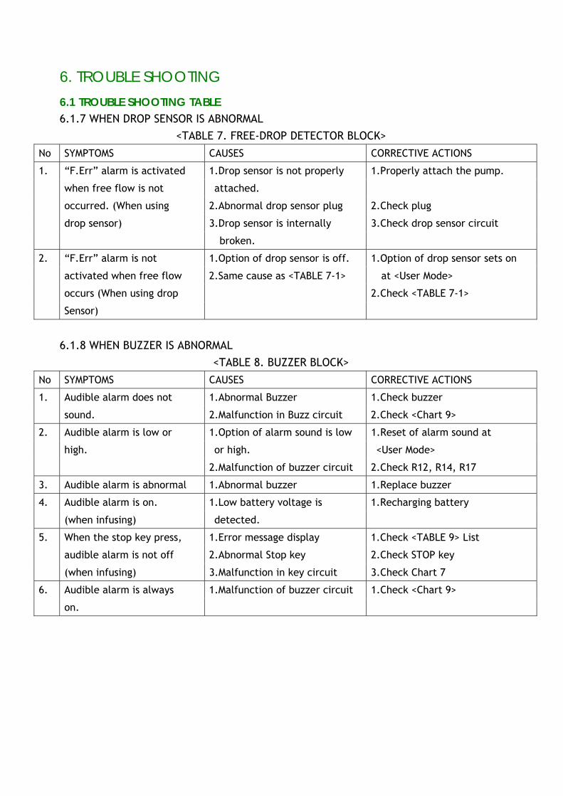
6.1 TROUBLE SHOOTING TABLE 6.1.7 WHEN DROP SENSOR IS ABNORMAL
<TABLE 7. FREE-DROP DETECTOR BLOCK>
No SYMPTOMS CAUSES CORRECTIVE ACTIONS
“F.Err” alarm is activated 1.Drop sensor is not properly 1.Properly attach the pump.
when free flow is not attached.
occurred. (When using 2.Abnormal drop sensor plug 2.Check plug
drop sensor) 3.Drop sensor is internally 3.Check drop sensor circuit
1.
broken.
“F.Err” alarm is not 1.Option of drop sensor is off. 1.Option of drop sensor sets on
activated when free flow 2.Same cause as <TABLE 7-1> at <User Mode>
occurs (When using drop 2.Check <TABLE 7-1>
2.
Sensor)
6.1.8 WHEN BUZZER IS ABNORMAL <TABLE 8. BUZZER BLOCK>
No SYMPTOMS CAUSES CORRECTIVE ACTIONS
Audible alarm does not 1.Abnormal Buzzer 1.Check buzzer 1.
sound. 2.Malfunction in Buzz circuit 2.Check <Chart 9>
Audible alarm is low or 1.Option of alarm sound is low 1.Reset of alarm sound at
high. or high. <User Mode>
2.
2.Malfunction of buzzer circuit 2.Check R12, R14, R17
3. Audible alarm is abnormal 1.Abnormal buzzer 1.Replace buzzer
Audible alarm is on. 1.Low battery voltage is 1.Recharging battery 4.
(when infusing) detected.
When the stop key press, 1.Error message display 1.Check <TABLE 9> List
audible alarm is not off 2.Abnormal Stop key 2.Check STOP key
5.
(when infusing) 3.Malfunction in key circuit 3.Check Chart 7
Audible alarm is always 1.Malfunction of buzzer circuit 1.Check <Chart 9> 6.
on.
6. TROUBLE SHOOTING
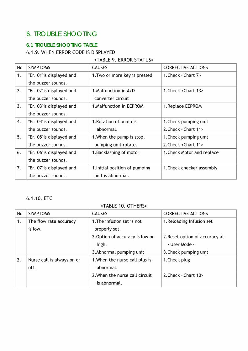
6.1 TROUBLE SHOOTING TABLE 6.1.9. WHEN ERROR CODE IS DISPLAYED
<TABLE 9. ERROR STATUS> No SYMPTOMS CAUSES CORRECTIVE ACTIONS
"Er. 01"is displayed and 1.Two or more key is pressed 1.Check <Chart 7> 1.
the buzzer sounds.
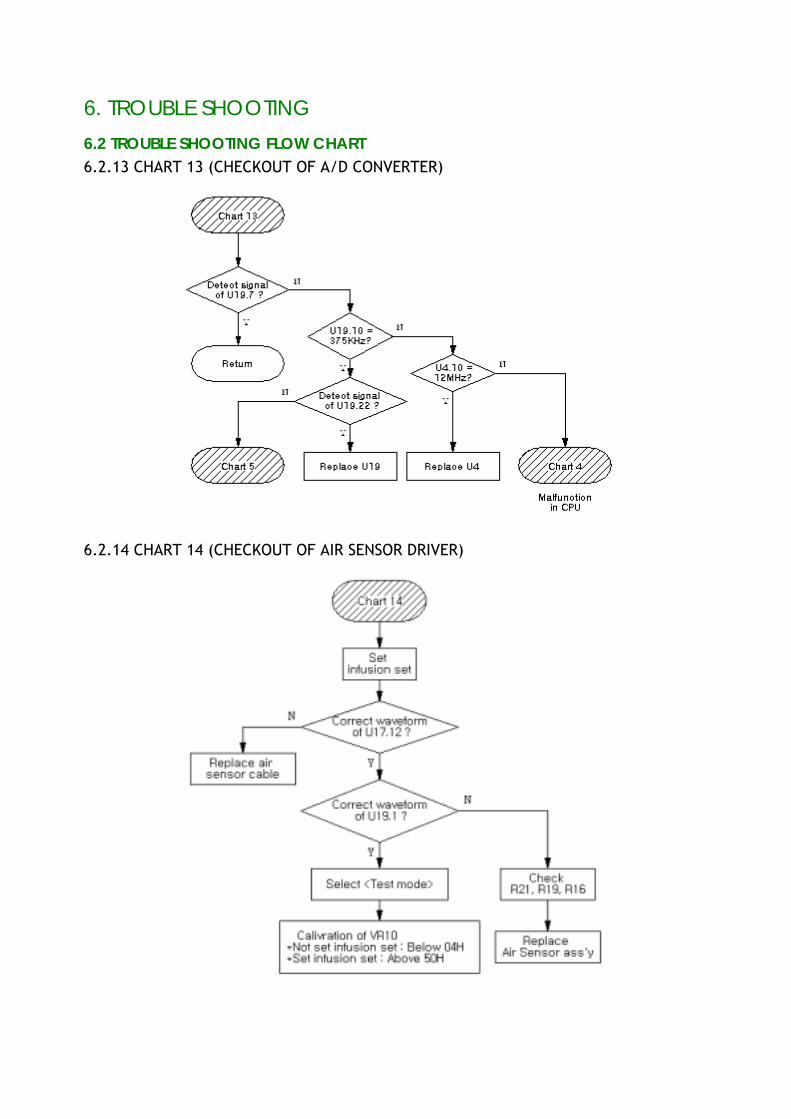
"Er. 02"is displayed and 1.Malfunction in A/D 1.Check <Chart 13> 2.
the buzzer sounds. converter circuit
"Er. 03"is displayed and 1.Malfunction in EEPROM 1.Replace EEPROM 3.
the buzzer sounds.
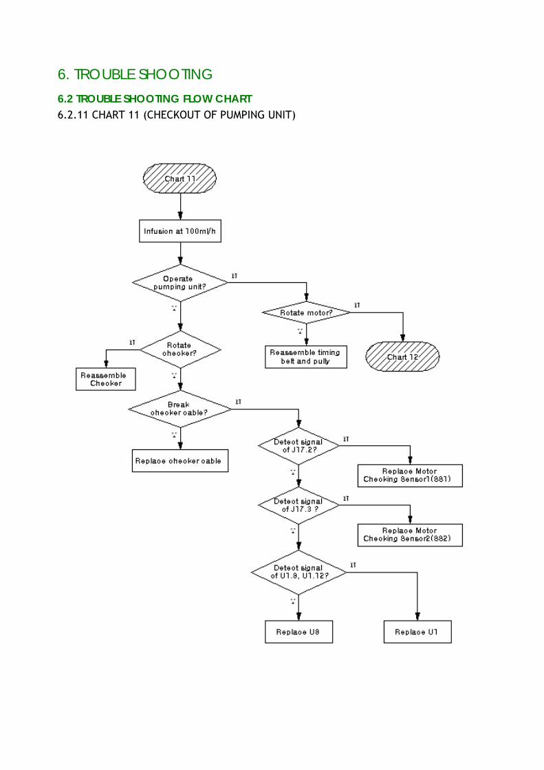
"Er. 04"is displayed and 1.Rotation of pump is 1.Check pumping unit 4.
the buzzer sounds. abnormal. 2.Check <Chart 11>
"Er. 05"is displayed and 1.When the pump is stop, 1.Check pumping unit 5.
the buzzer sounds. pumping unit rotate. 2.Check <Chart 11>
"Er. 06"is displayed and 1.Backlashing of motor 1.Check Motor and replace 6.
the buzzer sounds.
"Er. 07"is displayed and 1.Initial position of pumping 1.Check checker assembly 7.
the buzzer sounds. unit is abnormal.
6.1.10. ETC
<TABLE 10. OTHERS>
No SYMPTOMS CAUSES CORRECTIVE ACTIONS
The flow rate accuracy 1.The infusion set is not 1.Reloading Infusion set
is low. properly set.
2.Option of accuracy is low or 2.Reset option of accuracy at
high. <User Mode>
1.
3.Abnormal pumping unit 3.Check pumping unit
Nurse call is always on or 1.When the nurse call plus is 1.Check plug
off. abnormal.
2.When the nurse call circuit 2.Check <Chart 10>
2.
is abnormal.
6. TROUBLE SHOOTING
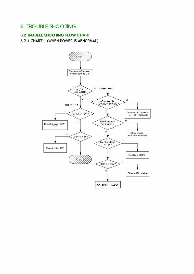
6.2 TROUBLE SHOOTING FLOW CHART 6.2.1 CHART 1 (WHEN POWER IS ABNORMAL)
6. TROUBLE SHOOTING
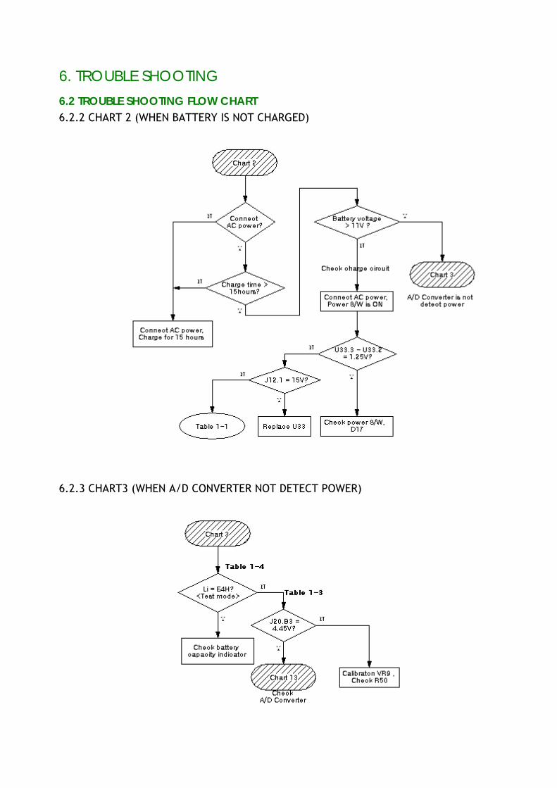
6.2 TROUBLE SHOOTING FLOW CHART 6.2.2 CHART 2 (WHEN BATTERY IS NOT CHARGED)
6.2.3 CHART3 (WHEN A/D CONVERTER NOT DETECT POWER)
6. TROUBLE SHOOTING
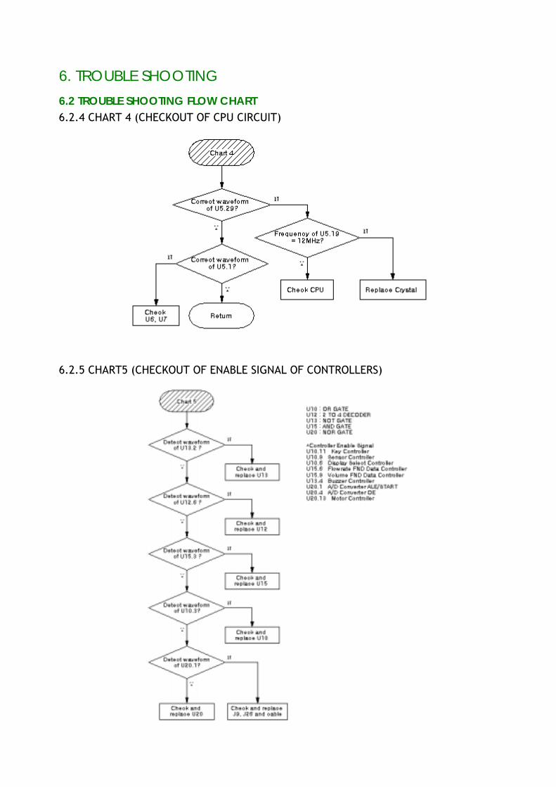
6.2 TROUBLE SHOOTING FLOW CHART 6.2.4 CHART 4 (CHECKOUT OF CPU CIRCUIT)
6.2.5 CHART5 (CHECKOUT OF ENABLE SIGNAL OF CONTROLLERS)
6. TROUBLE SHOOTING
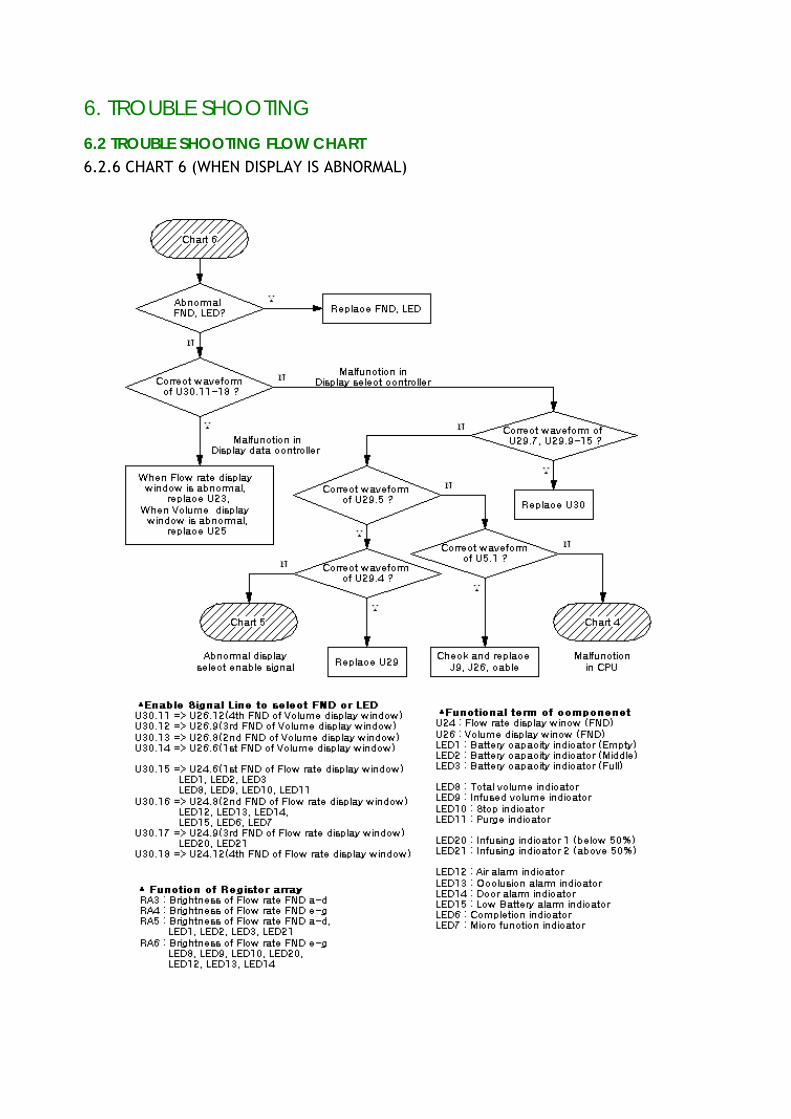
6.2 TROUBLE SHOOTING FLOW CHART 6.2.6 CHART 6 (WHEN DISPLAY IS ABNORMAL)
6. TROUBLE SHOOTING
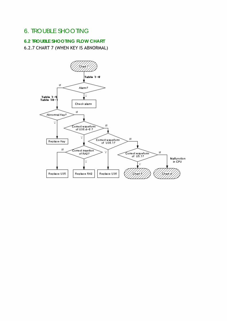
6.2 TROUBLE SHOOTING FLOW CHART 6.2.7 CHART 7 (WHEN KEY IS ABNORMAL)
6. TROUBLE SHOOTING
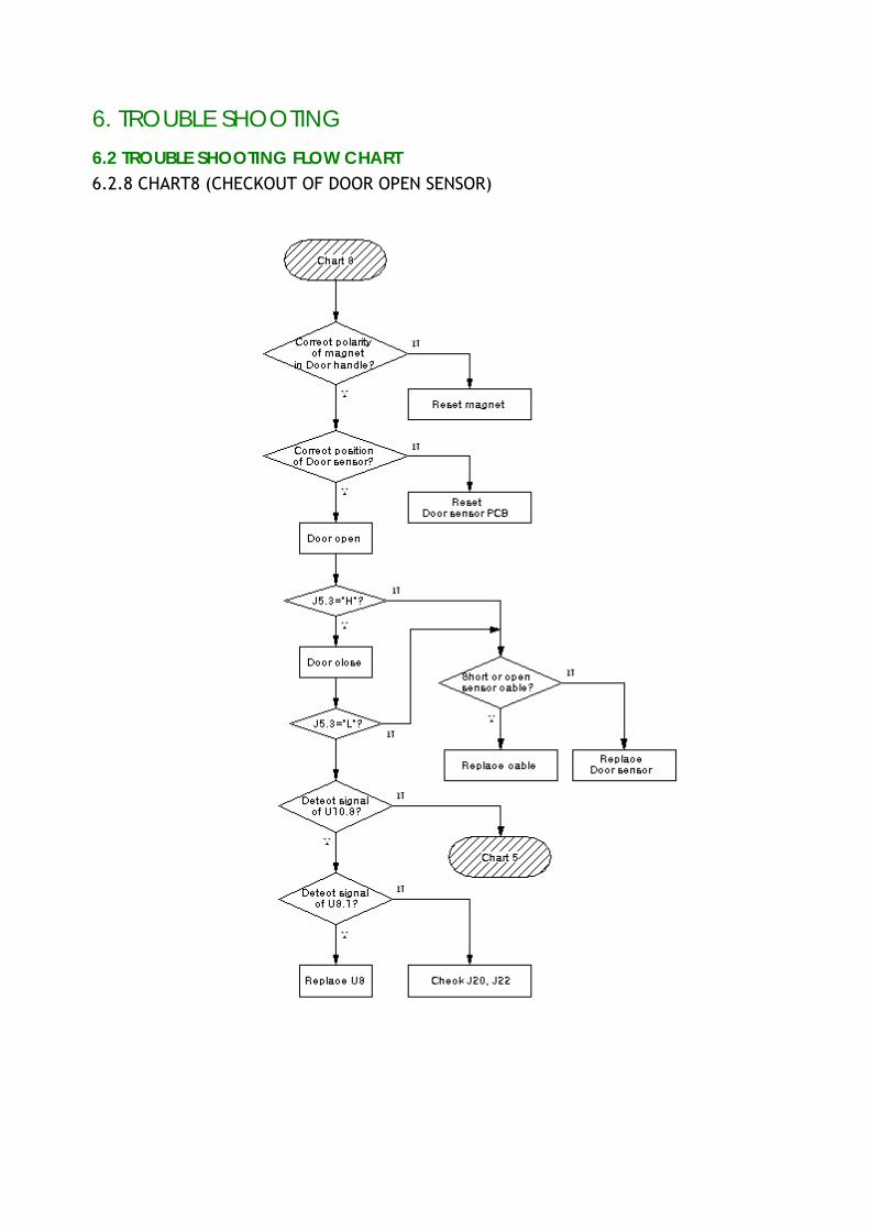
6.2 TROUBLE SHOOTING FLOW CHART 6.2.8 CHART8 (CHECKOUT OF DOOR OPEN SENSOR)
6. TROUBLE SHOOTING
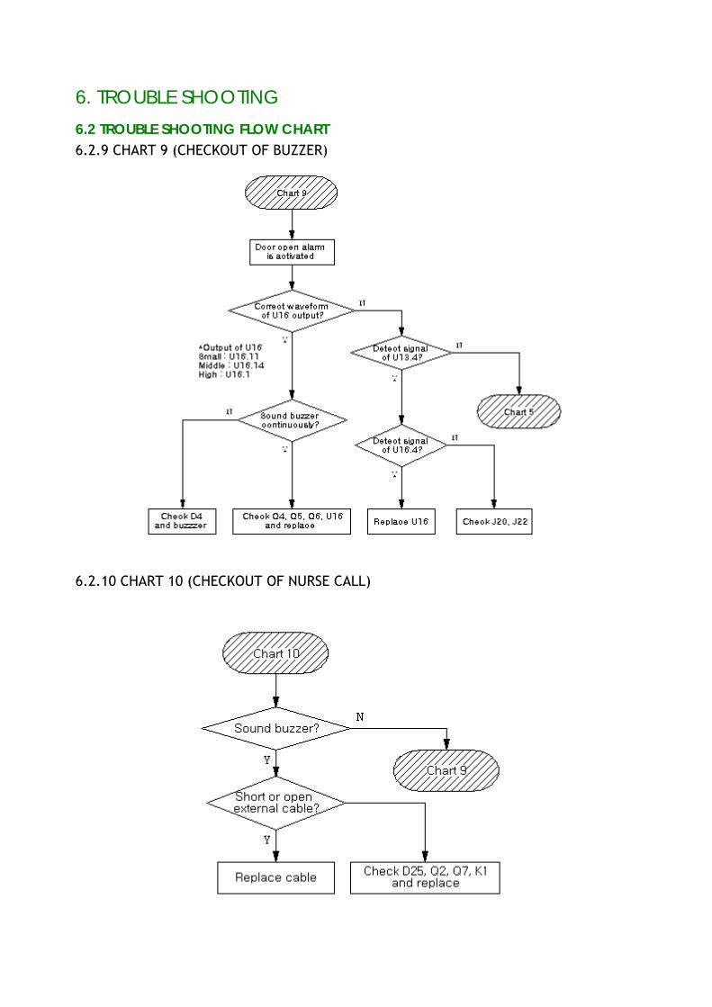
6.2 TROUBLE SHOOTING FLOW CHART 6.2.9 CHART 9 (CHECKOUT OF BUZZER)
6.2.10 CHART 10 (CHECKOUT OF NURSE CALL)
6. TROUBLE SHOOTING
6.2 TROUBLE SHOOTING FLOW CHART 6.2.11 CHART 11 (CHECKOUT OF PUMPING UNIT)
6. TROUBLE SHOOTING
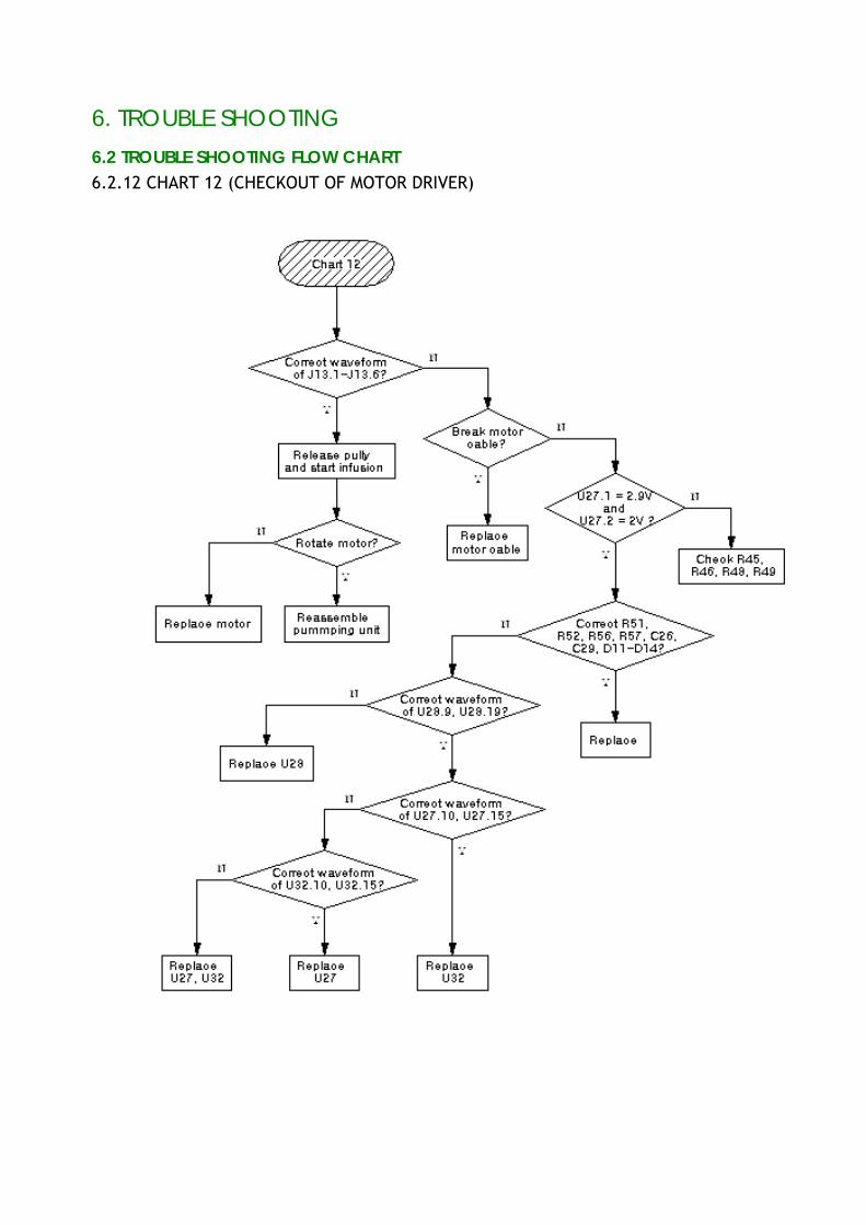
6.2 TROUBLE SHOOTING FLOW CHART 6.2.12 CHART 12 (CHECKOUT OF MOTOR DRIVER)
6. TROUBLE SHOOTING
6.2 TROUBLE SHOOTING FLOW CHART 6.2.13 CHART 13 (CHECKOUT OF A/D CONVERTER)
6.2.14 CHART 14 (CHECKOUT OF AIR SENSOR DRIVER)
6. TROUBLE SHOOTING
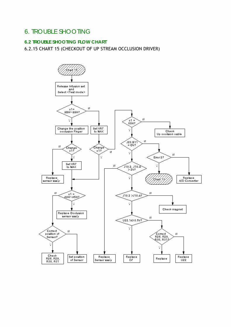
6.2 TROUBLE SHOOTING FLOW CHART 6.2.15 CHART 15 (CHECKOUT OF UP STREAM OCCLUSION DRIVER)
6. TROUBLE SHOOTING
6.2 TROUBLE SHOOTING FLOW CHART 6.2.16 CHART 16(CHECKOUT OF DOWN STREAM OCCLUSION DRIVER)
6. TROUBLE SHOOTING
6.2 TROUBLE SHOOTING FLOW CHART 6.2.17 CHART 17(WHEN POWER S/W IS ON, BATTERY CAPACITY INDICATOR IS OFF)
6. TROUBLE SHOOTING
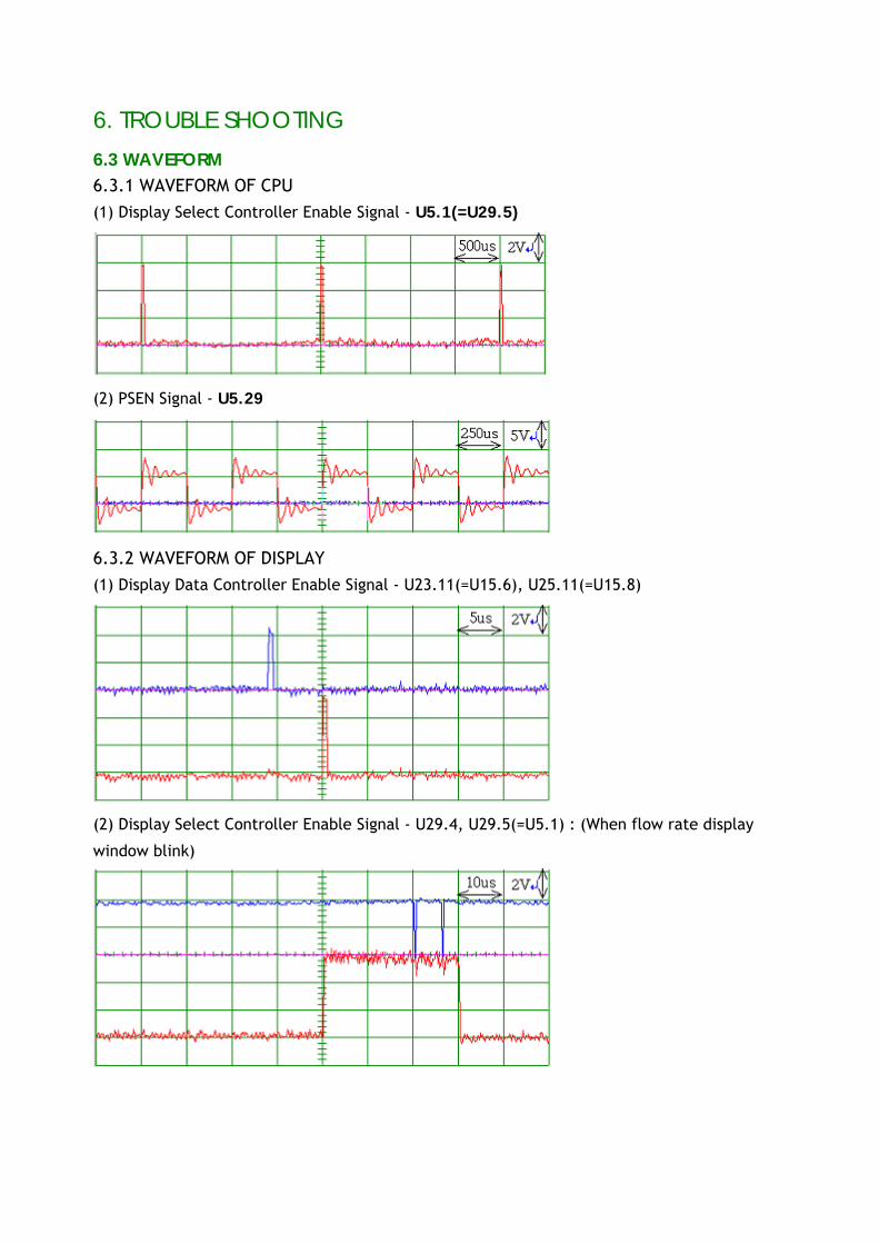
6.3 WAVEFORM 6.3.1 WAVEFORM OF CPU
(1) Display Select Controller Enable Signal - U5.1(=U29.5)
(2) PSEN Signal - U5.29
6.3.2 WAVEFORM OF DISPLAY
(1) Display Data Controller Enable Signal - U23.11(=U15.6), U25.11(=U15.8)
(2) Display Select Controller Enable Signal - U29.4, U29.5(=U5.1) : (When flow rate display
window blink)
6. TROUBLE SHOOTING
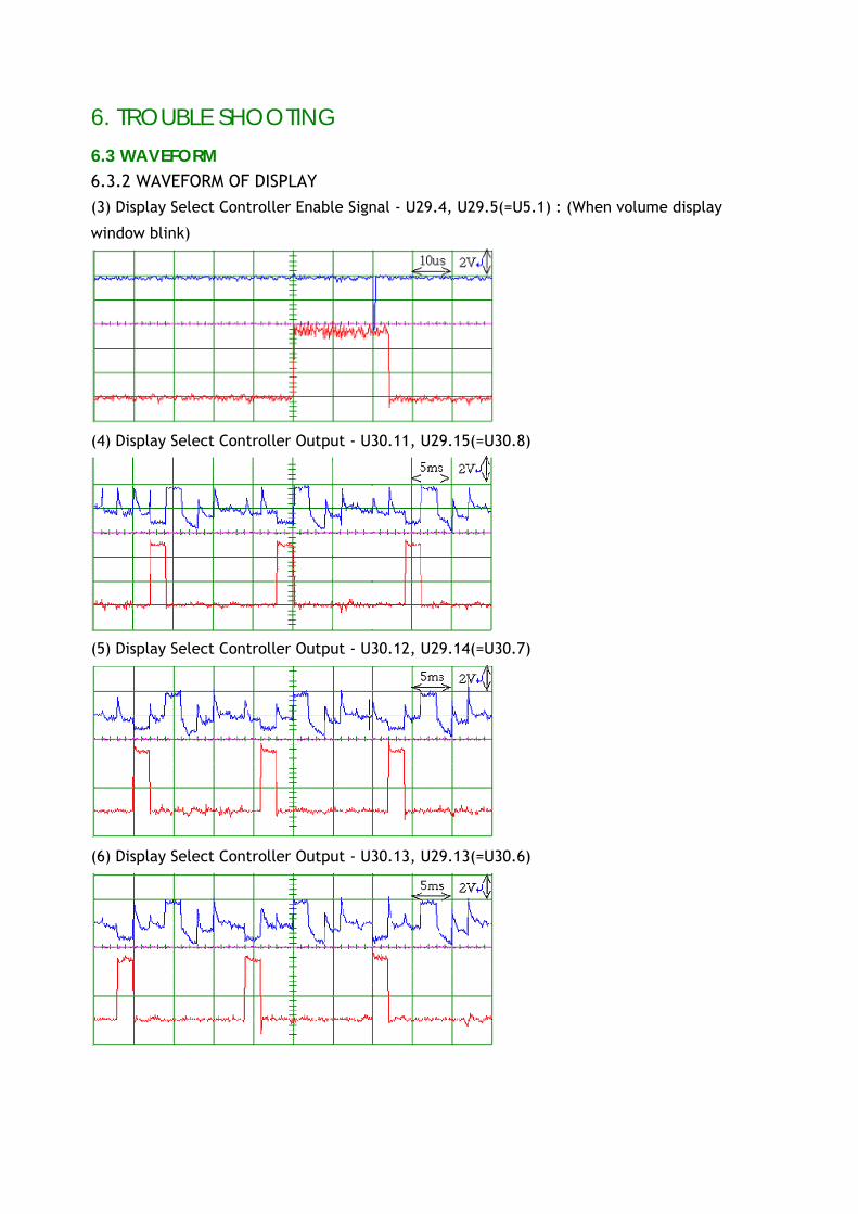
6.3 WAVEFORM
6.3.2 WAVEFORM OF DISPLAY (3) Display Select Controller Enable Signal - U29.4, U29.5(=U5.1) : (When volume display
window blink)
(4) Display Select Controller Output - U30.11, U29.15(=U30.8)
(5) Display Select Controller Output - U30.12, U29.14(=U30.7)
(6) Display Select Controller Output - U30.13, U29.13(=U30.6)
6. TROUBLE SHOOTING
6.3 WAVEFORM
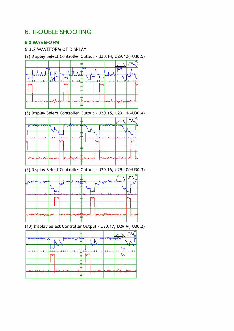
6.3.2 WAVEFORM OF DISPLAY
(7) Display Select Controller Output - U30.14, U29.12(=U30.5)
(8) Display Select Controller Output - U30.15, U29.11(=U30.4)
(9) Display Select Controller Output - U30.16, U29.10(=U30.3)
(10) Display Select Controller Output - U30.17, U29.9(=U30.2)
6. TROUBLE SHOOTING
6.3 WAVEFORM
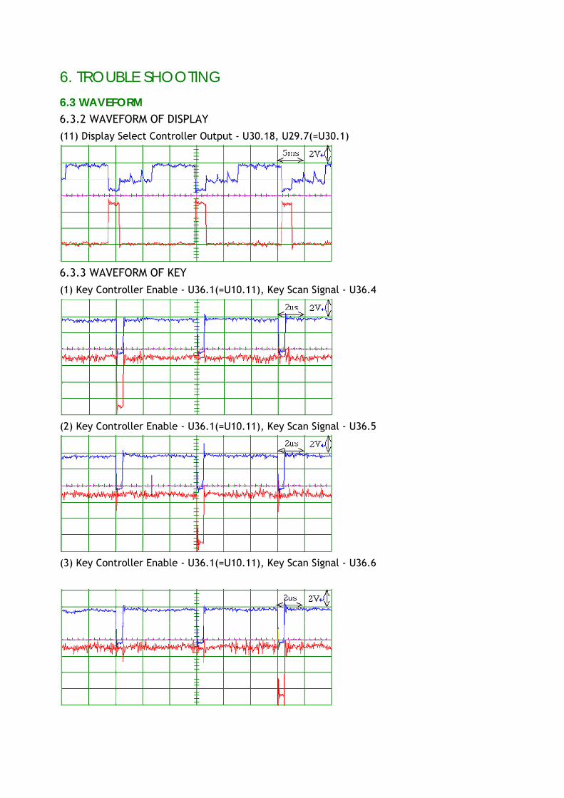
6.3.2 WAVEFORM OF DISPLAY (11) Display Select Controller Output - U30.18, U29.7(=U30.1)
6.3.3 WAVEFORM OF KEY (1) Key Controller Enable - U36.1(=U10.11), Key Scan Signal - U36.4
(2) Key Controller Enable - U36.1(=U10.11), Key Scan Signal - U36.5
(3) Key Controller Enable - U36.1(=U10.11), Key Scan Signal - U36.6
6. TROUBLE SHOOTING
6.3 WAVEFORM
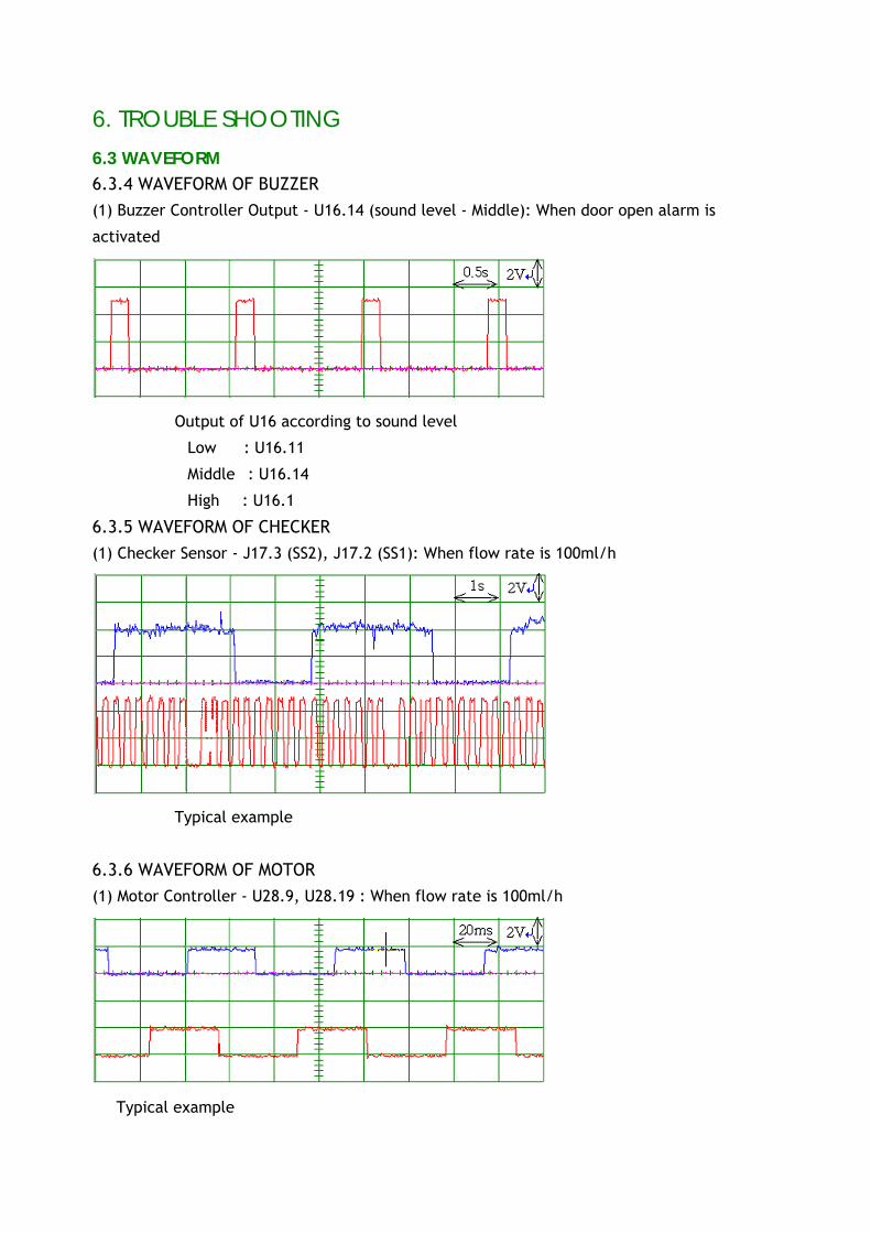
6.3.4 WAVEFORM OF BUZZER
(1) Buzzer Controller Output - U16.14 (sound level - Middle): When door open alarm is
activated
※ Output of U16 according to sound level
Low : U16.11
Middle : U16.14
High : U16.1
6.3.5 WAVEFORM OF CHECKER (1) Checker Sensor - J17.3 (SS2), J17.2 (SS1): When flow rate is 100ml/h
※ Typical example
6.3.6 WAVEFORM OF MOTOR
(1) Motor Controller - U28.9, U28.19 : When flow rate is 100ml/h
※ Typical example
6. TROUBLE SHOOTING
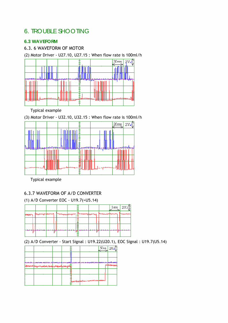
6.3 WAVEFORM
6.3. 6 WAVEFORM OF MOTOR (2) Motor Driver - U27.10, U27.15 : When flow rate is 100ml/h
※ Typical example
(3) Motor Driver - U32.10, U32.15 : When flow rate is 100ml/h
※ Typical example
6.3.7 WAVEFORM OF A/D CONVERTER
(1) A/D Converter EOC - U19.7(=U5.14)
(2) A/D Converter - Start Signal : U19.22(U20.1), EOC Signal : U19.7(U5.14)
6. TROUBLE SHOOTING
6.3 WAVEFORM
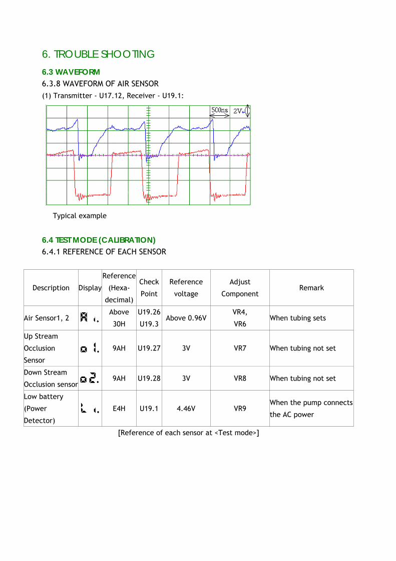
6.3.8 WAVEFORM OF AIR SENSOR (1) Transmitter - U17.12, Receiver - U19.1:
※ Typical example
6.4 TEST MODE (CALIBRATION) 6.4.1 REFERENCE OF EACH SENSOR
Description Display
Reference
(Hexa-
decimal)
Check
Point
Reference
voltage
Adjust
Component Remark
Air Sensor1, 2 Above
30H
U19.26
U19.3 Above 0.96V
VR4,
VR6 When tubing sets
Up Stream
Occlusion
Sensor 9AH U19.27 3V VR7 When tubing not set
Down Stream
Occlusion sensor 9AH U19.28 3V VR8 When tubing not set
Low battery
(Power
Detector) E4H U19.1 4.46V VR9
When the pump connects
the AC power
[Reference of each sensor at <Test mode>]
6. TROUBLE SHOOTING
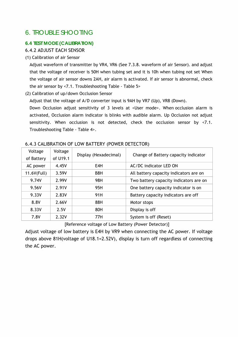
6.4 TEST MODE (CALIBRATION) 6.4.2 ADJUST EACH SENSOR (1) Calibration of air Sensor
Adjust waveform of transmitter by VR4, VR6 (See 7.3.8. waveform of air Sensor). and adjust
that the voltage of receiver is 50H when tubing set and it is 10h when tubing not set When
the voltage of air sensor downs 2AH, air alarm is activated. If air sensor is abnormal, check
the air sensor by <7.1. Troubleshooting Table - Table 5>
(2) Calibration of up/down Occlusion Sensor
Adjust that the voltage of A/D converter input is 9AH by VR7 (Up), VR8 (Down).
Down Occlusion adjust sensitivity of 3 levels at <User mode>. When occlusion alarm is
activated, Occlusion alarm indicator is blinks with audible alarm. Up Occlusion not adjust
sensitivity. When occlusion is not detected, check the occlusion sensor by <7.1.
Troubleshooting Table - Table 4>.
6.4.3 CALIBRATION OF LOW BATTERY (POWER DETECTOR)
Voltage
of Battery
Voltage
of U19.1 Display (Hexadecimal) Change of Battery capacity indicator
AC power 4.45V E4H AC/DC indicator LED ON
11.6V(Full) 3.59V B8H All battery capacity indicators are on
9.74V 2.99V 98H Two battery capacity indicators are on
9.56V 2.91V 95H One battery capacity indicator is on
9.33V 2.83V 91H Battery capacity indicators are off
8.8V 2.66V 88H Motor stops
8.33V 2.5V 80H Display is off
7.8V 2.32V 77H System is off (Reset)
[Reference voltage of Low Battery (Power Detector)]
Adjust voltage of low battery is E4H by VR9 when connecting the AC power. If voltage drops above 81H(voltage of U18.1=2.52V), display is turn off regardless of connecting the AC power.
7. DISASSEMBLY AND REASSEMBLY Disassembly of the Infusion pump MP-1000 is limited to the mechanical component and PCB assemblies. The pump that is dismantled or repaired without prior permission cannot receive a post-management service. Always make sure the pump is unplugged and that the pump is turn off before disassemble. Component of Infusion pump MP-1000 is sensitive to electrostatic discharge damage. Always disassemble and reassemble the pump on an anti-static mat.
7.1 SEPARATION OF FRONT CASE AND REAR CASE (SEE 8.5) 1) Turn the pump off and remove screw at rear case. Take care not to lay the pump
face down on components that could damage the front panel. 2) Separate the front and rear case by slowly lifting the rear case. 3) Avoid stressing the pump's internal cabling when separating the front and rear
case. 4) Stand the rear case horizontally 5) Disconnect the connectors, J11, J12 from the main rear PCB ass'y and disconnect
the connector J8 from the main front PCB ass'y and disconnect the ground cable from the power inlet
6) Reassemble case in reverse order. Verify cable route 7) Perform the operational checkout (See 3.)
7.2 REPLACEMENT OF PCB ASS'Y OF FRONT CASE (SEE 8.1)
1) Separate the front case and rear case completely. (See 7.1) 2) Disconnect the connectors, J13, J1, J5, J11, from the main rear PCB ass'y and
disconnect the connector J6 from the main front PCB ass'y 3) Remove screw of the main front PCB ass'y and lift main PCB ass'y. Then
disconnect connector, J22 from bottom of main front PCB ass'y. 4) Remove screw main rear PCB ass'y and separate main rear PCB ass'y and main
front PCB ass'y 5) Disconnect connector, J21 from the alarm PCB ass'y and remove screw of the
display and alarm PCB ass'y. Then separate the display and alarm PCB ass'y. 6) Reassemble PCB ass'y in reverse order.
7.DISASSEMBLY AND REASSEMBLY
7.3 REPLACEMENT OF AIR SENSOR ASS'Y (SEE 7.1)
1) Separate the front case and rear case completely. (See 7.1) 2) Disconnect connector of air sensor ass'y, J6 from the main front PCB ass'y and
remove screw of air sensor ass'y. 3) Separate air sensor ass'y and front case by lifting air sensor ass'y. 4) Reassemble the air sensor ass'y in reverse order. 5) Do not reuse the air sensor ass'y.
7.4 REPLACEMENT OF DOOR AND DOOR HANDLE (SEE 8.5)
1) Open the door and remove screw from door pin. 2) Pull bottom door pin up and pull top door pin down. Then separate door and
front case. 3) Remove pinhole cover and E-ring (82) from the door handle pin and push door
handle pin out of door and separate handle. 4) Reassemble the door and door handle in reverse order. 5) Do not reuse the E-ring
7.5. REPLACEMENT OF UP / DOWN STREAM OCCLUSION SENSOR (SEE 8.4)
1) Separate the front case and rear case completely. (See 7.1) 2) Disconnect the two connectors J10, J11 from Main front PCB ass'y. 3) Remove occlusion sensor PCB ass'y from occlusion sensor ass'y. 4) Separate the door. (See 7.4) 5) Remove screw from the occlusion sensor ass'y inside door, push the occlusion
sensor ass'y out of door 6) Reassemble the occlusion sensor ass'y in reverse order. 7) Do not reuse the PCB ass'y and sensor ass'y.
7.6. REPLACEMENT OF DOOR LATCH (SEE 8.1 AND 8.4)
1) Open the door. Remove screw from the slide knob and separate the knob. 2) Remove screws from the door latch and separate the door latch. 3) Reassemble the door latch in reverse order.
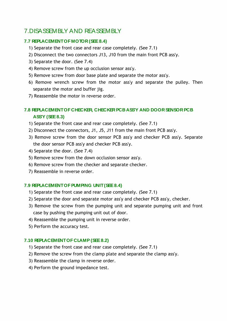
7.DISASSEMBLY AND REASSEMBLY 7.7 REPLACEMENT OF MOTOR (SEE 8.4)
1) Separate the front case and rear case completely. (See 7.1) 2) Disconnect the two connectors J13, J10 from the main front PCB ass'y. 3) Separate the door. (See 7.4) 4) Remove screw from the up occlusion sensor ass'y. 5) Remove screw from door base plate and separate the motor ass'y. 6) Remove wrench screw from the motor ass'y and separate the pulley. Then
separate the motor and buffer jig. 7) Reassemble the motor in reverse order.
7.8 REPLACEMENT OF CHECKER, CHECKER PCB ASS'Y AND DOOR SENSOR PCB ASS'Y (SEE 8.3)
1) Separate the front case and rear case completely. (See 7.1) 2) Disconnect the connectors, J1, J5, J11 from the main front PCB ass'y. 3) Remove screw from the door sensor PCB ass'y and checker PCB ass'y. Separate
the door sensor PCB ass'y and checker PCB ass'y. 4) Separate the door. (See 7.4) 5) Remove screw from the down occlusion sensor ass'y. 6) Remove screw from the checker and separate checker. 7) Reassemble in reverse order.
7.9 REPLACEMENT OF PUMPING UNIT (SEE 8.4)
1) Separate the front case and rear case completely. (See 7.1) 2) Separate the door and separate motor ass'y and checker PCB ass'y, checker. 3) Remove the screw from the pumping unit and separate pumping unit and front
case by pushing the pumping unit out of door. 4) Reassemble the pumping unit in reverse order. 5) Perform the accuracy test.
7.10 REPLACEMENT OF CLAMP (SEE 8.2)
1) Separate the front case and rear case completely. (See 7.1) 2) Remove the screw from the clamp plate and separate the clamp ass'y. 3) Reassemble the clamp in reverse order. 4) Perform the ground impedance test.
7.DISASSEMBLY AND REASSEMBLY 7.11 REPLACEMENT OF EXTERNAL CONNECTOR PCB ASS'Y AND DC JACK PCB
ASS'Y, POWER SWITCH (SEE 8.2)
1) Separate the front case and rear case completely. (See 7.1) 2) Remove the screw from the external PCB ass'y and DC jack PCB ass'y. Separate
the external PCB ass'y and DC jack PCB ass'y. 3) Separate power switch from the rear case by pushing 4) Reassemble the clamp in reverse order.
7.12 REPLACEMENT OF SMPS (SEE 8.2)
1) Separate the front case and rear case completely. (See 7.1) 2) Remove cable from the SMPS 3) Remove label and screw, then separate SMPS. 4) Reassemble the clamp in reverse order. 5) Perform the ground impedance test.
7.13 REPLACEMENT OF POWER INLET (SEE 8.2)
1) Separate the front case and rear case completely. (See 7.1) 2) Separate External PCB ass'y and DC jack PCB ass'y. 3) Remove cable from the power inlet. 4) Separate connector hole cover and DC jack hole cover. 5) Remove inlet label. 6) Remove screw and separate power inlet. 7) Reassemble the clamp in reverse order. 8) Perform the ground impedance test.
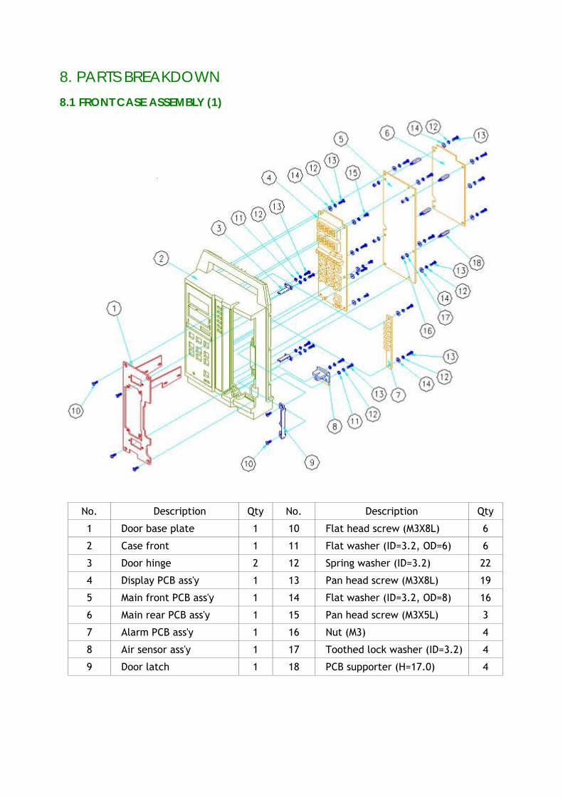
8. PARTS BREAKDOWN 8.1 FRONT CASE ASSEMBLY (1)
No. Description Qty No. Description Qty
1 Door base plate 1 10 Flat head screw (M3X8L) 6
2 Case front 1 11 Flat washer (ID=3.2, OD=6) 6
3 Door hinge 2 12 Spring washer (ID=3.2) 22
4 Display PCB ass'y 1 13 Pan head screw (M3X8L) 19
5 Main front PCB ass'y 1 14 Flat washer (ID=3.2, OD=8) 16
6 Main rear PCB ass'y 1 15 Pan head screw (M3X5L) 3
7 Alarm PCB ass'y 1 16 Nut (M3) 4
8 Air sensor ass'y 1 17 Toothed lock washer (ID=3.2) 4
9 Door latch 1 18 PCB supporter (H=17.0) 4
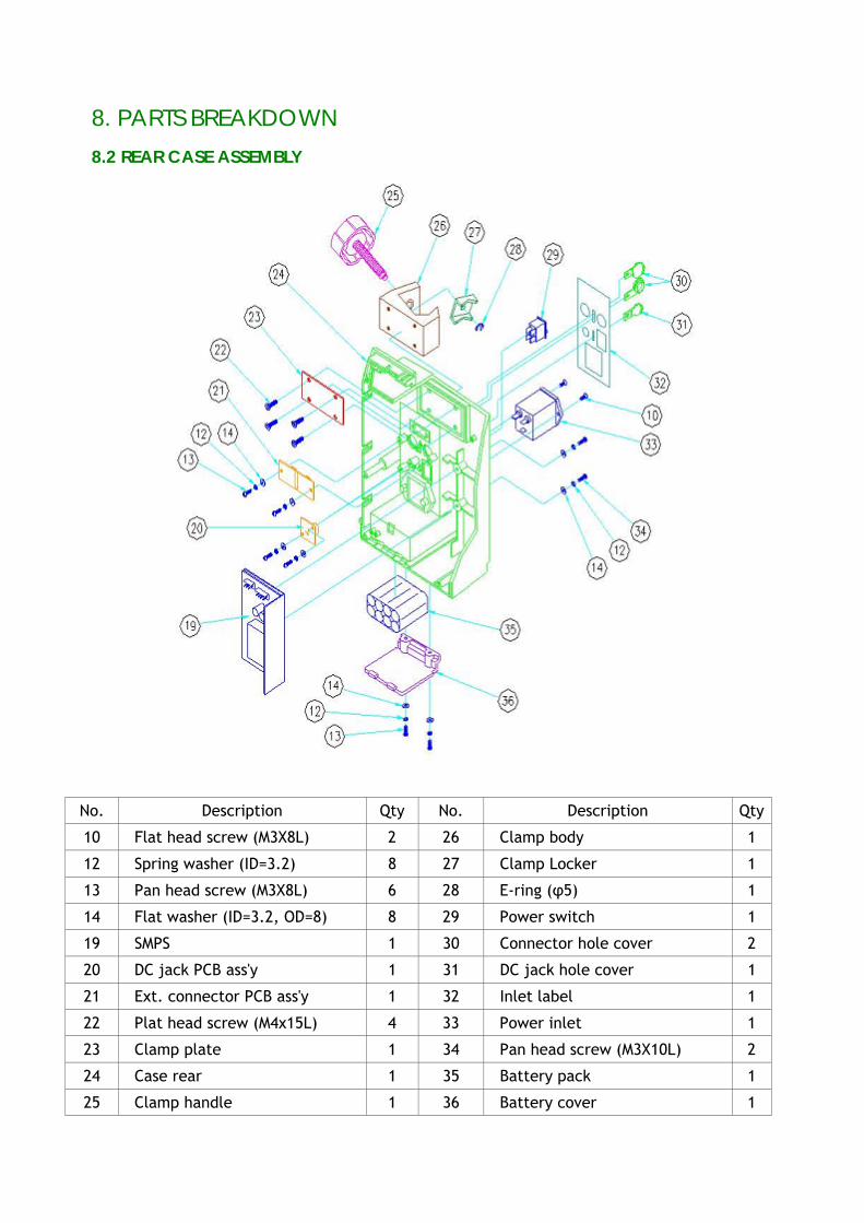
8. PARTS BREAKDOWN 8.2 REAR CASE ASSEMBLY
No. Description Qty No. Description Qty
10 Flat head screw (M3X8L) 2 26 Clamp body 1
12 Spring washer (ID=3.2) 8 27 Clamp Locker 1
13 Pan head screw (M3X8L) 6 28 E-ring (φ5) 1
14 Flat washer (ID=3.2, OD=8) 8 29 Power switch 1
19 SMPS 1 30 Connector hole cover 2
20 DC jack PCB ass'y 1 31 DC jack hole cover 1
21 Ext. connector PCB ass'y 1 32 Inlet label 1
22 Plat head screw (M4x15L) 4 33 Power inlet 1
23 Clamp plate 1 34 Pan head screw (M3X10L) 2
24 Case rear 1 35 Battery pack 1
25 Clamp handle 1 36 Battery cover 1
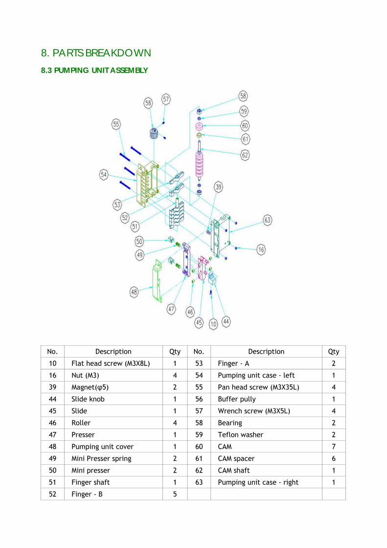
8. PARTS BREAKDOWN
8.3 PUMPING UNIT ASSEMBLY
No. Description Qty No. Description Qty
10 Flat head screw (M3X8L) 1 53 Finger - A 2
16 Nut (M3) 4 54 Pumping unit case - left 1
39 Magnet(φ5) 2 55 Pan head screw (M3X35L) 4
44 Slide knob 1 56 Buffer pully 1
45 Slide 1 57 Wrench screw (M3X5L) 4
46 Roller 4 58 Bearing 2
47 Presser 1 59 Teflon washer 2
48 Pumping unit cover 1 60 CAM 7
49 Mini Presser spring 2 61 CAM spacer 6
50 Mini presser 2 62 CAM shaft 1
51 Finger shaft 1 63 Pumping unit case - right 1
52 Finger - B 5
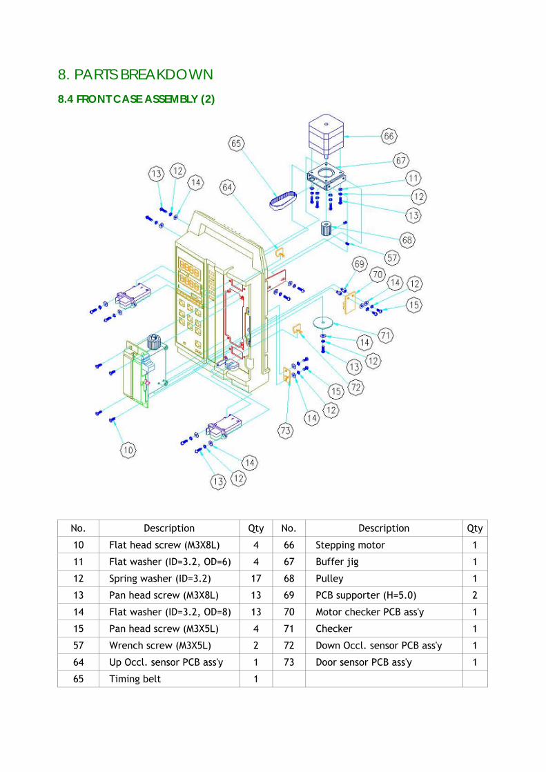
8. PARTS BREAKDOWN
8.4 FRONT CASE ASSEMBLY (2)
No. Description Qty No. Description Qty
10 Flat head screw (M3X8L) 4 66 Stepping motor 1
11 Flat washer (ID=3.2, OD=6) 4 67 Buffer jig 1
12 Spring washer (ID=3.2) 17 68 Pulley 1
13 Pan head screw (M3X8L) 13 69 PCB supporter (H=5.0) 2
14 Flat washer (ID=3.2, OD=8) 13 70 Motor checker PCB ass'y 1
15 Pan head screw (M3X5L) 4 71 Checker 1
57 Wrench screw (M3X5L) 2 72 Down Occl. sensor PCB ass'y 1
64 Up Occl. sensor PCB ass'y 1 73 Door sensor PCB ass'y 1
65 Timing belt 1
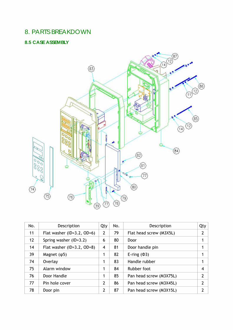
8. PARTS BREAKDOWN
8.5 CASE ASSEMBLY
No. Description Qty No. Description Qty
11 Flat washer (ID=3.2, OD=6) 2 79 Flat head screw (M3X5L) 2
12 Spring washer (ID=3.2) 6 80 Door 1
14 Flat washer (ID=3.2, OD=8) 4 81 Door handle pin 1
39 Magnet (φ5) 1 82 E-ring (Φ3) 1
74 Overlay 1 83 Handle rubber 1
75 Alarm window 1 84 Rubber foot 4
76 Door Handle 1 85 Pan head screw (M3X75L) 2
77 Pin hole cover 2 86 Pan head screw (M3X45L) 2
78 Door pin 2 87 Pan head screw (M3X15L) 2
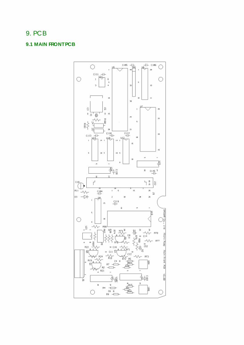
9. PCB 9.1 MAIN FRONT PCB
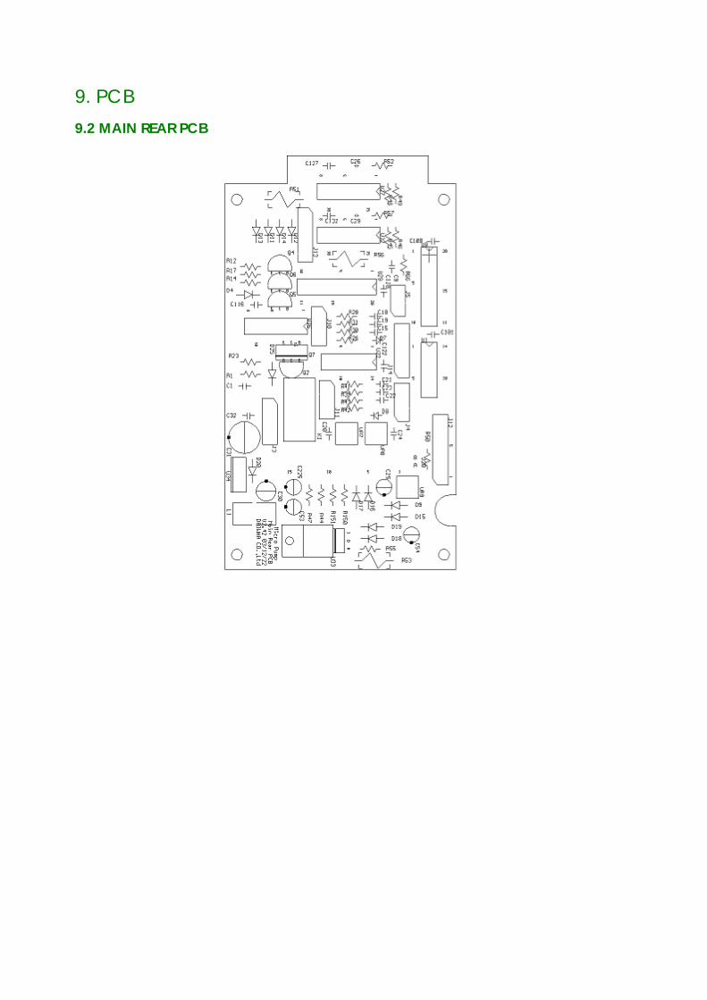
9. PCB 9.2 MAIN REAR PCB
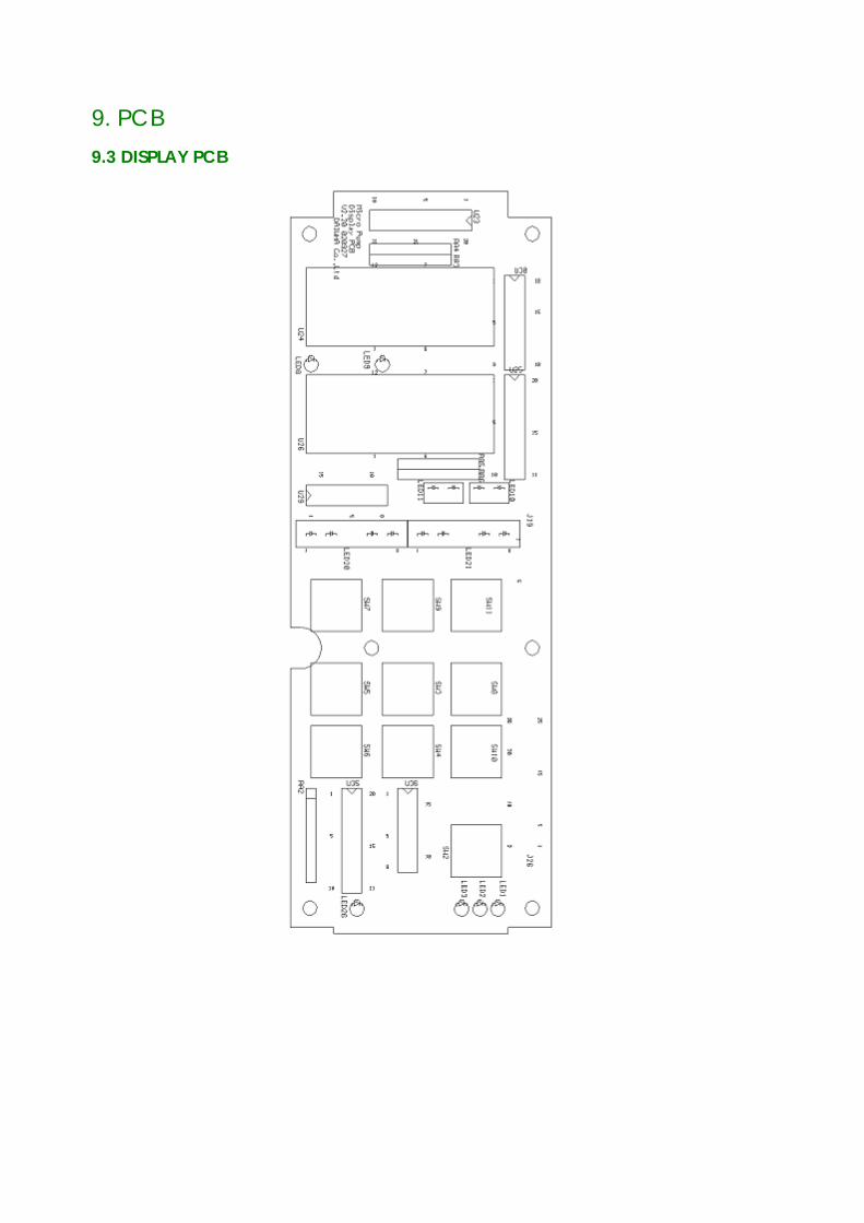
9. PCB 9.3 DISPLAY PCB
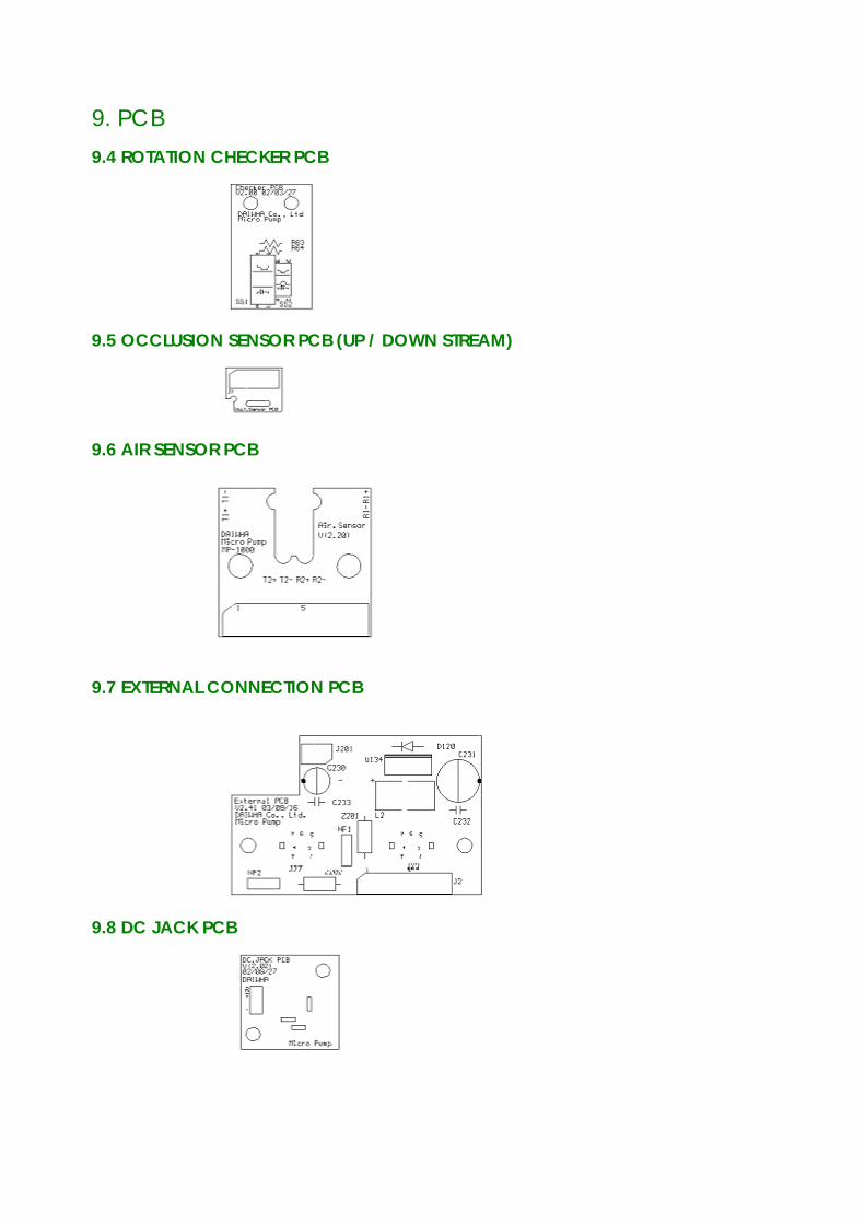
9. PCB 9.4 ROTATION CHECKER PCB
9.5 OCCLUSION SENSOR PCB (UP / DOWN STREAM)
9.6 AIR SENSOR PCB
9.7 EXTERNAL CONNECTION PCB
9.8 DC JACK PCB
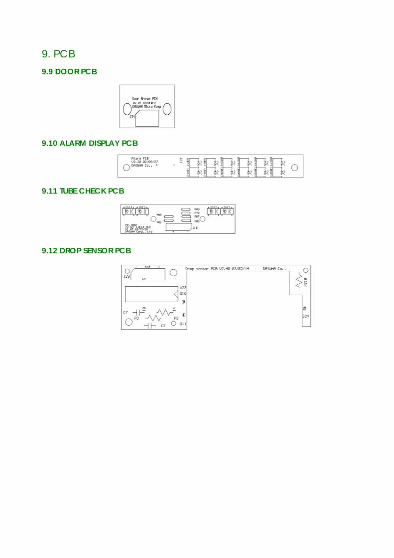
9. PCB 9.9 DOOR PCB
9.10 ALARM DISPLAY PCB
9.11 TUBE CHECK PCB
9.12 DROP SENSOR PCB

10. SCHEMATIC
INTENTIONAL BLANK
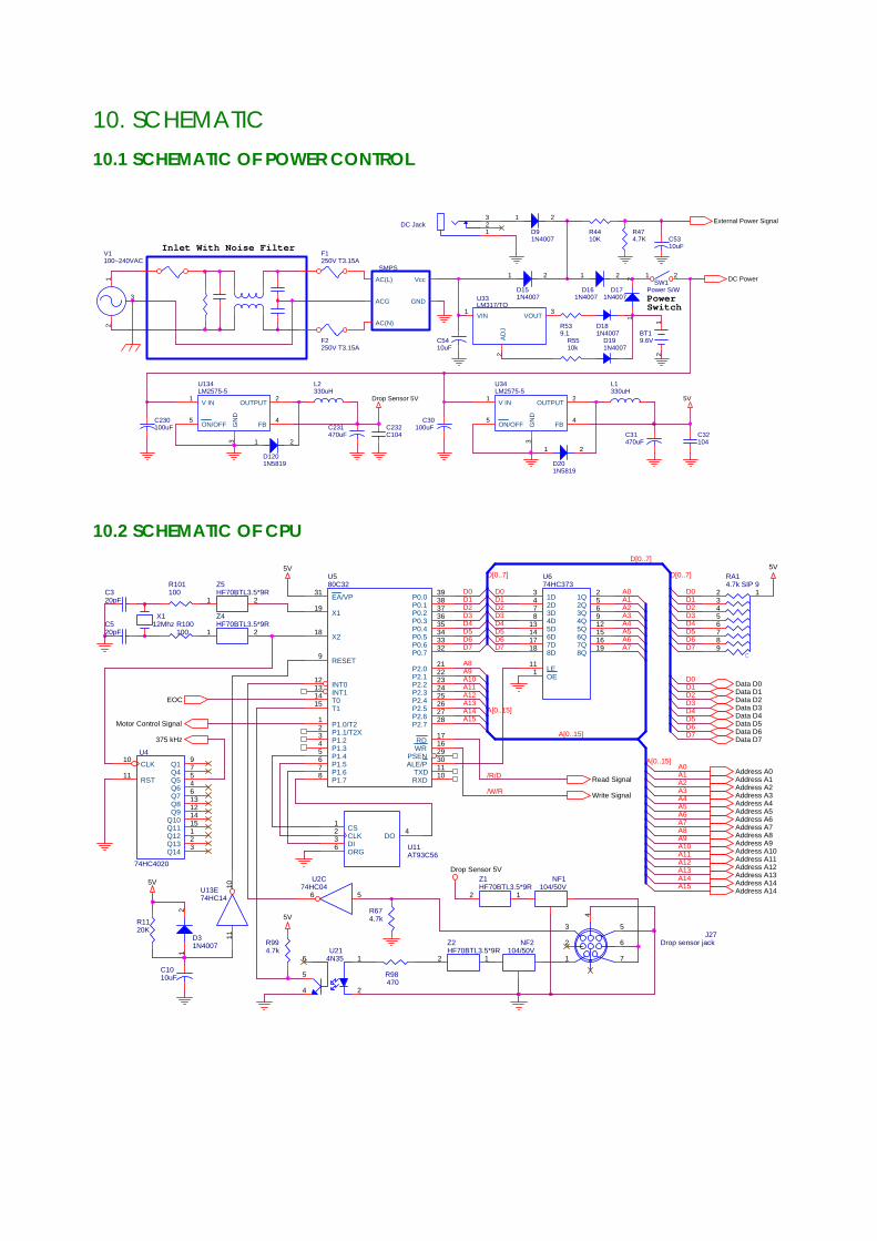
10. SCHEMATIC 10.1 SCHEMATIC OF POWER CONTROL
SMPS
Vcc
GND
AC(L)
ACG
AC(N)
D171N4007
12
D181N4007
5VDrop Sensor 5V
L2330uH
DC Jack123
R539.1
C31470uF
PowerSwitch
L1330uH
R4410K
F1250V T3.15A
Inlet With Noise Filter
U33LM317/TO
1 3
2
VIN VOUT
AD
J
C32104
D191N4007
V1100~240VAC
12
3
R474.7K
C5410uF
C230100uF
D1201N5819
1 2
External Power Signal
F2250V T3.15A
D91N4007
1 2
C231470uF
C5310uF
U134LM2575-5
1 2
3
45
V IN OUTPUT
GN
D
FBON/OFF
SW1Power S/W
1 2
BT19.6V
12
C232C104
C30100uF
D201N5819
1 2
U34LM2575-5
1 2
3
45
V IN OUTPUT
GN
D
FBON/OFF
DC Power
D151N4007
1 2
D161N4007
1 2
R5510k
10.2 SCHEMATIC OF CPU
A12
A0
D2
A3/W/R
A15
D7A7
A15
A1D2
D5
A10
D4
A1
D7
A2
D6
A11
D[0..7]
A3 D3D4
D1
D4A[0..15]
A14
A12
D6
A[0..15]
D5
A6
A10
D[0..7]
D5
D6
A4
D3A4
D0
D2
A0
A14
D7
D0
D4
/R/D
A2
A9
A9
D6
D[0..7]
A5
D1
D3D2
A8
A8
A[0..15]
A6
D0
D0
A13
A11
D3
D5
D1
A13
D1
A5
D7
A7
Data D0
Address A11
R98470
Data D2
Data D4
NF1104/50V
Address A5
5V
C320pF
Z4HF70BTL3.5*9R
1 2
Z1HF70BTL3.5*9R
12
Address A4
Address A7
EOC
Address A14
5V
Drop Sensor 5V
Z5HF70BTL3.5*9R
1 2
5V
Address A0
Address A2
Address A13
Data D7
Address A12
5V
U580C32
31
19
18
9
12131415
12345678
3938373635343332
2122232425262728
171629301110
EA/VP
X1
X2
RESET
INT0INT1T0T1
P1.0/T2P1.1/T2XP1.2P1.3P1.4P1.5P1.6P1.7
P0.0P0.1P0.2P0.3P0.4P0.5P0.6P0.7
P2.0P2.1P2.2P2.3P2.4P2.5P2.6P2.7
RDWR
PSENALE/P
TXDRXD
375 kHz
Data D5
Address A9
J27Drop sensor jack
1
2
3
4
5
6
7
Address A6
U214N35 16
2
5
4
Data D3
Address A10
Read Signal
Address A14
NF2104/50V
R101100
AT93C56U11
123
4
6
CSCLKDI
DO
ORG
R674.7k
C1010uF
R100100
Data D1
U4
74HC4020
10
11
9754613121415123
CLK
RST
Q1Q4Q5Q6Q7Q8Q9
Q10Q11Q12Q13Q14
Motor Control Signal
Address A8
Address A3
U674HC373
111
256912151619
3478
13141718
OELE
1Q2Q3Q4Q5Q6Q7Q8Q
1D2D3D4D5D6D7D8D
Write Signal
D31N4007
12
R1120K
Data D6
C520pF
U13E74HC14
1110
R994.7k
Address A1
C
RA14.7k SIP 9
123456789
X112Mhz
U2C74HC04
56
Z2HF70BTL3.5*9R
12
10. SCHEMATIC
10.3 SCHEMATIC OF ADDRESS DECODER
Read SignalBuzzer Control Signal
Motor Control SignalU20D74HC02
11
1213
U13B74HC14
3 4
U13D74HC14
9 8
FND1 Control Signal
Sensor Selection Signal
ADC Read Signal
Write Signal
Address A14
Address A5
U12A74LS139
23
1
4567
AB
G
Y0Y1Y2Y3
U15B74HC08
4
56
U12B74LS139
15
1211109
AB
G
Y0Y1Y2Y3
Address A15
Address A9
ADC Write Signal
U15A74HC08 1
23
Address A13
U10B74HC32
4
56 Display Selection Signal
U20B74HC02
5
64
FND2 Control Signal
U10D74HC32
12
1311
U20A74HC022
31
U10C74HC32
9
108
Address A4
U13A74HC14
1 2
Key Control Signal
Address A8
U10A74HC32
1
23
U15C74HC089
108
A15
A14
1413A9
A13
/R/D
/W/R
A8
A5
A4
D0
D5
D3
D2
D4
D4
A2
D5
D7
A0
D0
D2
D7
D1
D6
D1
D6
A1
D3
10.4 SCHEMATIC OF DISPLAY CONTROL
LED6Green
Micro
LED21SBD446G
7
1 2
8
3 4
5 64_A
1_A 1_C
4_C
2_A 2_C
3_A 3_C
Data D4
LED13Red
Display Selection Signal
Data D3
LED8Yellow
Data D1
DOOR OPEN
AC/DC
LED10RED
Data D6
INFUSED VOLUME
LED14Red
LED3GREEN
U2574HC373
111
256912151619
3478
13141718
OELE
1Q2Q3Q4Q5Q6Q7Q8Q
1D2D3D4D5D6D7D8D
STOP
LED11Yellow
RA668Y
12345678
12345678
LED9Yellow
External Power Signal
U2374HC373
111
256912151619
3478
13141718
OELE
1Q2Q3Q4Q5Q6Q7Q8Q
1D2D3D4D5D6D7D8D
Address A2
Data D3
Data D6
AIR
TOTAL VOLUME
U26SND540BUG
117421
1053
6
8
9
12
ABCDEFGDP
DIG.4
DIG.3
DIG.2
DIG.1
CHARGE3
Address A0
CHARGE1
COMPLETE
Data D5
LED7Yellow
Data D2
LED26Red
Data D4
LOW BATTERY
CHARGE2Data D7
U30TD62083
12345678
10
18
11121314151617I1
I2I3I4I5I6I7I8
COM
O1
O8O7O6O5O4O3O2
LED20SBD446G
7
1 2
8
3 4
5 64_A
1_A 1_C
4_C
2_A 2_C
3_A 3_C
LED15Green
Volume
Data D5
RA368Y
12345678
12345678
LED12Red
PURGE
U24SND540BUG
117421
1053
6
8
9
12
ABCDEFGDP
DIG.4
DIG.3
DIG.2
DIG.1
FND2 Control Signal
Flow Rate
LED2GREEN
Data D2
FND1 Control Signal
LED1GREEN
Data D0
RA568Y
12345678
12345678
OCCLUSION
5V
RA468Y
12345678
12345678
Data D0
R58120
Data D7
U2974HC237
123
16
15141312111097
654
ABC
VCC
Y0Y1Y2Y3Y4Y5Y6Y7
G1G2GL
Address A1
Display Control Signal
Data D1
10. SCHEMATIC
10.5 SCHEMATIC OF MOTOR CONTROL
5V
R5247K
D121N5817
R453.3K
Data D5
U32A3955SB
12
3
4 5 1312
78
6
149
10
11
15
16
PFDREF
RC
GN
DG
ND
GN
DG
ND
PhaseD2
Vss
D0D1
OUTa
Sense
OUTb
Vbb
Data D7
D131N5817
Motor Control Signal
Data D0
Data D4
R4920K
Data D2
D111N5817
Data D3
R464.7k
5V
R5747K
R511.2
U27A3955SB
12
3
4 5 1312
78
6
149
10
11
15
16
PFDREF
RC
GN
DG
ND
GN
DG
ND
PhaseD2
Vss
D0D1
OUTa
Sense
OUTb
Vbb
5V
D141N5817
Data D1
C29470pF
R561.2
C26470pF
MG1Stepping Motor
1
3
4 6
Data D6
U2874HC373
111
20
256912151619
3478
13141718
OELE
VCC
1Q2Q3Q4Q5Q6Q7Q8Q
1D2D3D4D5D6D7D8D
R4830K
DC Power
D0
D3D4
D6
Motor CTRL
D1
D7
D5
D2
C000H
Up Stream
Air 2
Power
A0
D7
A2
D1Down Stream
D4
D2
A1
D3
D6D5
C005H
D0Air 1
10.6 SCHEMATIC OF AD CONVERTER
ADC Read Signal
C1620pF
+
-
U22BLM29025
67
411
1N4148D2
U2F74HC04
13 12
C20104
R39300K
C410pF
S6Air sensor 2
+-
+-
Address A1
ADC Write Signal
Data D1
C52102
5V
R1351K
EOC
U2A74HC04
1 2
Data D3
R731.8k
R24470k
R161.8k
Data D7
R74470k
VR65021 3
2
R281K
VR45021 3
2
5V
C22104
R41.2K
R4210K
Air 2
5V
300KR43
Address A0
Q92SC1815
R51.2K
5V
Data D6
5V
C24104
R71470k
C19104
R21.2K
R201.8k
C25
10uF
VR710K
13
2
R61.2K
D71N4148
DC Power
R22100k
R75100k
C820pF
R761.8k
C21104
R7920k
C18104 Address A2
Data D4
C1220pF
R8020k
R19100k
R1551K
THS119
VccOUT(+)
GNDOUT(-)
R5010K
5V
5V
C610pF
5V
5V
C23104
R751K
375 kHz
D81N4148
R72100k
C15104
R31300K
U2B74HC04
3 4
U19ADC0809
26272812345
1216
10
97
171415818192021
252423
622
IN0IN1IN2IN3IN4IN5IN6IN7
REF+REF-
CLK
OEEOC
D0D1D2D3D4D5D6D7
A0A1A2
STARTALE
Data D5
+-
U3ALM339
7
61
312 R10
51K
5V
THS119
VccOUT(+)
GNDOUT(-)
R77470k
Data D0
5V
C1120pF
R411K
VR810K
13
2
D11N4148
Air 1
VR910K
13
2
U2E74HC04
11 10 C14102
Data D2
R21470k
Q12SC1815
R951K
R78470k
Q82SC1815
R1851K
Q32SC1815
+-
U3CLM339
9
814
312
+
-
U22DLM290212
1314
411
5V
R3010K
5V
R26300K
S1Air sensor 1
+-
+-
10. SCHEMATIC
10.7 SCHEMATIC OF ADDITIONAL SENSOR
R6420k
R6222
5V
R7022
Data D6
U1D74HC14
98
5V
R61330
U1F74HC14
1312
Data D0
R6620k
SS4UGS3144
Vcc
OUT
GND
Data D7
SS1SG207
Data D3
R664.7K
U1F74HC14
1312
R6720k
Data D5
SS11SG215
SS13SG215
R6820k
74HC244U8
3579
12141618
17151311
8642
191
2Y42Y32Y22Y1
1Y41Y31Y21Y1
2A42A32A22A1
1A41A31A21A1
2OE1OE
Data D4
SS14SG215
R6022
C9104
SS12SG215
SS2SG215
R6320k
Data D1
R69330
5V
U1E74HC14
1110
Sensor Selection Signal
U1A74HC14
12
U1B74HC14
34
R59330
R6520k
Data D2
D0
CHK4
D2
CHK2
D1
D5
D3
D6
CHK1
CHK3
D4
D7
D7
D1D2
D0
D3
D5D6
D4
A0A1
10.8 SCHEMATIC OF KEY CONTROL
SW111103W
12
Data D0
Data D5
SW51103W
12
Data D3
SHIFT
UP
Address A1
PURGE
SW81103W
12
U36A74HC139
23
1
4567
AB
G
Y0Y1Y2Y3
Data D6START
SW41103W
12
SW91103W
12
STOP/CLEAR
SW31103W
12
T.VOL
I.VOL
SW21103W
1 2
Data D4
Address A0
C
RA24.7k SIP 91
2 3 4 5 6 7 8 9
ON/OFF
SW71103W
12
Data D1
SW101103W
12
SW61103W
1274HC244U35
3579
12141618
17151311
8642
191
2Y42Y32Y22Y1
1Y41Y31Y21Y1
2A42A32A22A1
1A41A31A21A1
2OE1OE
DOWN
Data D2
Key Control Signal
Data D7
F.RATE
5V
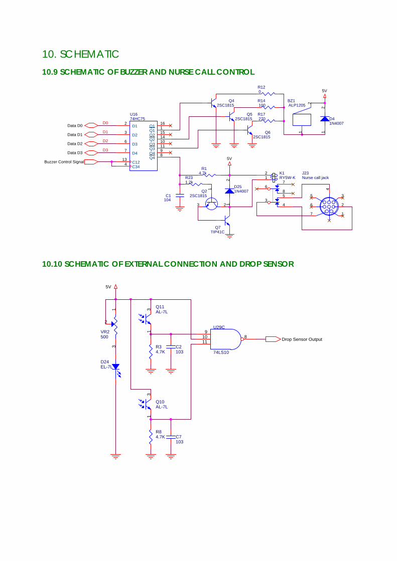
10. SCHEMATIC 10.9 SCHEMATIC OF BUZZER AND NURSE CALL CONTROL
Q52SC1815
J23Nurse call jack
1
2
3
4
5
6
7
BZ1ALP1205
1
2
Data D2
5V
R14100
Q7TIP41C
D251N4007
12
Data D0
R120
C1104
R231.2k
Data D1
Buzzer Control Signal
U1674HC75
2
3
6
7
134
1611514101198
D1
D2
D3
D4
C12C34
Q1Q1Q2Q2Q3Q3Q4Q4
R17270
Q42SC1815
Data D3
R14.7k
D41N4007
12
Q22SC1815
123
5V
K1RY5W-K
34
5
68
712
Q62SC1815
D0
D3
D1
D2
10.10 SCHEMATIC OF EXTERNAL CONNECTION AND DROP SENSOR
VR2500
13
2
C7103
D24EL-7L
Q10AL-7L
13
C2103
R84.7K
U29C
74LS10
91011
8
R34.7K
Drop Sensor Output
Q11AL-7L
13
5V