Embed Size (px)
Citation preview

M & D SPECIALISEDFASTENERS cc.
COMMERCIAL PRODUCTS PageDIMENSIONS
ISO Metric Mild Steel Hexagon Bolts, Screws and Nuts 1ISO Metric Mild Steel Cup Square Bolts 2ISO Metric Mild Steel Set Screws 3ISO Metric Mild Steel Nuts 3ISO Metric Mild Steel Countersunk Nib Bolts 4ISO Metric Mild Steel Countersunk Square Bolts 4
HIGH TENSILE AND PRECISION PRODUCTSDIMENSIONS
ISO Metric Precision Hexagon Bolts 5ISO Metric Precision Hexagon Set Screws 5ISO Metric Precision Hexagon Nuts 6ISO Metric Friction Grip Bolts 6ISO Metric Friction Grip Nuts 6Dimensions of Flat Round Chamfered Washers through hardened 7Unified Precision Hexagon Bolts and Set Screws 8Unified Precision Hexagon Nuts 8
SCREW PRODUCTSSOCKET HEAD CAP SCREWS
ISO Metric Socket Head Cap Screws 9Unified Inch (1960) Socket Head Cap Screws 10BS Inch Socket Head Cap Screws 11
FLAT HEAD SOCKET SCREWSISO Metric Flat Head Socket Screws 12Unified Inch Flat Head Socket Screws 13
SOCKET SCREWSISO Metric Socket Button Head Screws 14Metric Socket Shoulder Screws 14ISO Metric Socket Set Screws 15 & 16
DIMENSIONSSlotted and Pozidriv Wood Screws 20Hammer Drive Screws 20Pozidriv Self Tapping Screws Types AB and B 21Pozidriv and Hex Self Tapping Screws Types AB and B 21Self Tapping Thread Form and Point Details 22Slotted Self Tapping Screws Types AB and B 23Pozidriv Machine Screws 24Taptite Thread Forming Screws 25
PILOT HOLE SIZES (SCREWS)Taptite Thread Forming Screws 25Self Tapping Screws(Case Hardened Steel Screws and 18/8 Stainless Steel Screws) 26Hammer Drive Screws 26
TECHNICAL INFORMATION (SCREWS)Technical Data for ISO Metric Slotted Machine Screws 27Suggested Tightening Torques (ISO Metric Slotted Machine Screws) 27Recommended Torsional Strength for Self Tapping Screws 22
HIGH STRENGTH FRICTION GRIP BOLTSTechnical Information and Methods of Torque Tightening 28A Guide to the Selection of Torque Values 32
WRENCHESISO Metric High Titan Hexagon Wrenches 17
PINSMetric Dowel Pins 18Metric Sel-Lok Spring Pins 19
METRIC-IMPERIAL CONVERSIONS AND FACTORS 34
ISO STRENGTH GRADES FOR STEEL BOLTS, STUDS AND NUTS 34
MECHANICAL PROPERTIESISO Metric Friction Grip Bolts and Nuts 7 & 30ISO Metric Steel Bolts, Screws and Studs 35Proof Load Properties ISO Metric Steel Nuts 36Proof Load Properties ISO Metric Steel Bolts and Screws 36UNC/ UNF Bolts and Set Screws 37UNC/ UNF Nuts 37Imperial Strength Grades - Steel Bolts, Screws, Studs and Nuts 38Strength Grade Comparisons Steel Bolts, Screws and Studs 38
CORROSION PROTECTIONUSE OF CORROSION RESISTANT FINISHES 39USE OF CORROSION RESISTANT MATERIALS(STAINLESS STEEL PRODUCTS) 40
MATERIALS FOR STAINLESS STEEL FASTENERS 41
STAINLESS STEEL FASTENERS IN CONTACT WITHOTHER MATERIALS 45
M & D SPECIALISED FASTENERS cc.Tel: (011) 868-1172 Fax: (011) 868-1190
e-mail: [email protected] Website: www.m-d.co.za 550 Delfos Avenue, Alrode South P.O. Box 136174, Alberton North, 1456
M & D SPECIALISED FASTENERS cc.
Index
R
R
R
R
R
R

M & D SPECIALISEDFASTENERS cc.
M & D SPECIALISED FASTENERS cc.REG NO. CK 87/21963/23
NOTE:* For SABS 135 bolts only* Din 601 is always 2d + 6
I.S.O. Metric Mild SteelHexagon Bolts,Screws and Nuts(SABS 135/DIN 555)
1
M & D SPECIALISED FASTENERS cc.
25
30
35
40
45
50
55
60
65
70
75
80
90
100
110
120
130
140
150
160
180
200
220
240
260
280
300
SET & NUT XOX(Hexagon Head Bolts and Nuts)- Mild SteelQuantity per 25kg bag
LENGTHK S
M
THREAD LENGTH
E
d
NB
m
Dimension M36
4,0
37,00
35,00
55,00
53,80
24,05
21,95
29,65
28,35
M33
3,5
34,0
32,0
50,0
49,0
22,05
19,95
27,05
24,95
M30
3,5
30,84
29,16
46,00
45,00
20,05
17,95
24,65
23,35
(M27)
3,0
27,84
26,16
41,0
40,0
17,9
16,1
23,05
20,95
M24
3,0
24,84
23,16
36,00
35,00
15,90
14,10
19,65
18,35
M22
2,5
22,84
21,16
34,0
33,0
14,9
13,1
18,90
17,10
M20
2,5
20,84
19,16
30,00
29,16
13,90
12,10
16,55
15,45
M16
2,0
16,70
15,30
24,00
23,16
10,45
9,55
13,55
12,45
M12
1,75
12,70
11,30
19,00
18,48
8,45
7,55
10,45
9,55
M10
1,5
10,58
9,42
17,00
16,57
7,45
6,55
8,45
7,55
M8
1,25
8,58
7,42
13,00
12,57
5,88
5,13
6,88
6,13
M6
1,0
6,48
5,52
10,00
9,64
4,38
3,63
5,38
4,63
Pitch of Thread
Max.
Min.
Max.
Min.
Max.
Min.
Max.
Min.
d
s
k
m
Diameter
Nominal Length
Up to and including 65 mm
Over 65 mm up to and
including 125 mm
Up to and including 125 mm
Over 125 mm up to and
including 200 mm
Over 200 mm
Nominal Dia.
M16-M24
M6-M12
M27-M36
M6-M36
Thread Length
1,5 d *
2d + 6*
2d + 12
2d + 25
THREAD LENGTH ON BOLTS
Dia 6
P=1.00
2758
2464
-
2049
-
1760
-
-
1401
-
1258
-
1084
1001
-
868
803
774
744
681
672
-
-
-
-
-
-
Dia 8
P=1.25
1382
1265
1177
1058
985
915
853
-
736
-
686
328
583
531
501
457
443
414
389
377
332
-
-
-
-
-
-
Dia 10
P=1.50
790
728
680
648
582
547
512
-
461
-
415
-
364
328
305
285
270
246
237
227
205
184
179
161
145
140
127
Dia 12
P=1.75
526
496
680
435
406
388
352
-
314
-
283
-
249
228
214
176
183
173
162
155
140
128
129
108
102
95
91
Dia 16
P=2.00
242
232
216
206
196
185
177
170
157
151
145
137
126
117
109
102
95
90
85
81
75
68
63
59
55
51
49
Dia 20
P=2.50
-
-
-
114
110
105
100
96
93
89
84
80
75
69
65
61
58
55
53
50
45
42
39
36
34
32
30
Dia 24
P=3.00
-
-
-
-
-
65
63
60
58
57
55
54
50
45
43
41
38
36
35
33
30
28
26
24
23
21
20
Dia 27
P=3.00
-
-
-
-
-
-
-
-
-
-
-
-
-
30
30
30
30
-
-
-
-
-
-
-
-
-
-
Dia 30
P=3.00
-
-
-
-
-
-
-
-
32
31
31
30
28
27
26
24
22
21
20
20
18
10
16
15
14
13
12
????
P=4.00
-
-
-
-
-
-
-
-
-
-
19
-
15
10
10
10
10
10
10
10
10
10
10
10
10
9
9
M & D SPECIALISEDFASTENERS cc.
20
25
30
35
40
45
50
55
65
75
90
100
110
120
130
140
150
160
180
200
220
240
260
280
300
M & D SPECIALISED FASTENERS cc.REG NO. CK 87/21963/23
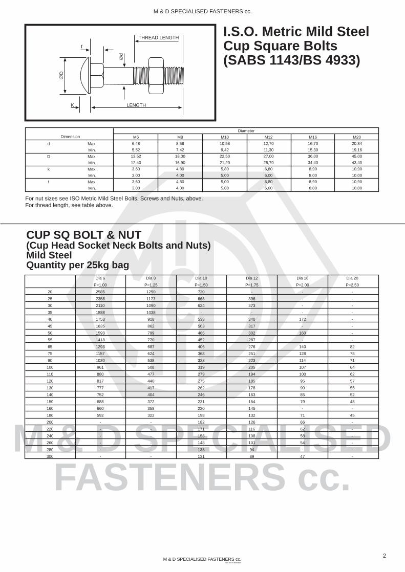
I.S.O. Metric Mild SteelCup Square Bolts(SABS 1143/BS 4933)
Dimension M20
20,84
19,16
45,00
43,40
10,90
10,00
10,90
10,00
M16
16,70
15,30
36,00
34,40
8,90
8,00
8,90
8,00
M12
12,70
11,30
27,00
25,70
6,80
6,00
6,80
6,00
M10
10,58
9,42
22,50
21,20
5,80
5,00
5,00
5,80
M8
8,58
7,42
18,00
16,90
4,80
4,00
4,80
4,00
M6
6,48
5,52
13,52
12,40
3,60
3,00
3,60
3,00
Max.
Min.
Max.
Min.
Max.
Min.
Max.
Min.
d
D
k
f
Diameter
For nut sizes see ISO Metric Mild Steel Bolts, Screws and Nuts, above.For thread length, see table above.
LENGTHK
THREAD LENGTH
d
f
D
2
M & D SPECIALISED FASTENERS cc.
CUP SQ BOLT & NUT(Cup Head Socket Neck Bolts and Nuts)Mild SteelQuantity per 25kg bag
Dia 6
P=1.00
2585
2358
2110
1888
1753
1635
1593
1418
1293
1157
1030
961
880
817
777
752
688
660
592
-
-
-
-
-
-
Dia 8
P=1.25
1250
1177
1090
1038
918
862
799
770
687
624
538
508
477
440
417
404
372
358
322
-
-
-
-
-
-
Dia 10
P=1.50
720
668
624
-
538
503
466
452
406
368
323
319
279
275
262
246
231
220
198
182
171
158
148
138
131
Dia 12
P=1.75
-
396
373
-
340
317
302
287
276
251
223
205
194
185
178
163
154
145
132
126
116
108
101
94
89
Dia 16
P=2.00
-
-
-
-
172
-
160
-
140
128
114
107
100
95
90
85
79
-
71
66
62
58
54
-
47
Dia 20
P=2.50
-
-
-
-
-
-
-
-
82
78
71
64
62
57
55
52
48
-
45
-
-
-
-
-
-

M & D SPECIALISEDFASTENERS cc.
M & D SPECIALISED FASTENERS cc.REG NO. CK 87/21963/23
I.S.O. Metric Mild SteelSet Screws(DIN 558/ SABS 135)
3
M & D SPECIALISED FASTENERS cc.
NOTE:P = Thread pitch
Thread size M5
0,8
3,5
3,12
3,88
8
7,64
Nominal size
min.
max.
max. - nominal size
min.
P )
k
s
1
M6
1
4
3,62
4,38
10
9,64
M8
1,25
5,3
4,92
5,68
13
12,57
M10
1,5
6,4
5,95
6,85
17
16,57
M12
1,75
7,5
7,05
7,95
19
18,48
M16
2
10
9,25
10,75
24
23,16
M20
2,5
12,5
11,6
13,4
30
29,16
M24
3
15
14,1
15,9
36
35
M30
3,5
18,7
17,65
19,75
46
45
M36
4
22,5
21,45
23,55
55
53,8
1
NOTE:P = Thread pitch
Thread size (d) M5
0,8
6,7
8,63
4
4,6
3,4
2,7
8
7,64
min.
min.
nominal size
max.
min.
min.
max = nominal size
min.
P )
k
s
1
1
M6
1
8,7
10,89
5
5,6
4,4
3,5
10
9,64
M8
1,25
11,5
14,2
6,5
7,25
5,75
4,6
13
12,57
M10
1,5
15,5
18,72
8
8,75
7,25
5,8
17
16,57
M12
1,75
17,2
20,88
10
10,75
9,25
7,4
19
18,48
M16
2
22
26,17
13
13,9
12,1
9,7
24
23,16
M20
2,5
27,7
32,95
16
16,9
15,1
12,1
30
29,16
(M22)
2,5
29,5
35,03
18
18,9
17,1
13,7
32
31
M24
3
33,2
39,55
19
20,05
17,95
14,4
36
35
(M27)
3
38
45,2
22
23,05
20,95
16,8
41
40
M30
3,5
42,7
50,85
24
25,05
22,95
18,4
46
45
M36
4
51,1
60,79
29
30,05
27,95
22,4
55
53,8
(M33)
3,5
46,5
55,37
26
27,05
24,95
20
50
49
I.S.O. MetricMild Steel Nuts(DIN 555/SABS 135)
15 to 30
s
NB
m’
d
d w
m
m1
m’ - Minimum wrenching height (0,8 m minimum).
Countersink at start of threadpermissible at either side.
151
e
Size
12
16
20
25
30
35
40
45
50
55
60
65
70
75
80
85
90
95
100
M6
4772
4640
4289
3763
3205
2906
2716
2403
2232
2083
1985
1811
1756
1664
1569
1445
1429
1315
1297
M8
2578
2379
2129
1874
1663
1524
1388
1250
1178
1077
1008
966
896
862
803
764
730
698
684
M10
1235
1151
1040
949
879
813
752
705
623
608
578
525
517
498
424
410
M12
725
698
656
592
552
511
476
435
409
393
366
348
339
309
284
M16
362
328
303
281
262
244
232
218
207
195
187
173
DIN 558 Approximate count per 25kg bag
K S
NB
m
M & D SPECIALISEDFASTENERS cc.
M & D SPECIALISED FASTENERS cc.REG NO. CK 87/21963/23
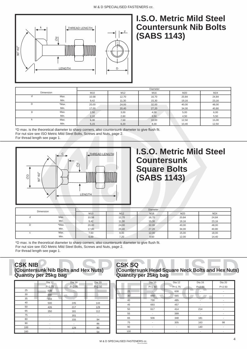
I.S.O. Metric Mild SteelCountersunk Nib Bolts(SABS 1143)
I.S.O. Metric Mild SteelCountersunkSquare Bolts(SABS 1143)
LENGTH
THREAD LENGTH
d
k
D
90 /
92
y
4
M & D SPECIALISED FASTENERS cc.
*D max. is the theoretical diameter to sharp corners, also countersunk diameter to give flush fit.For nut size see ISO Metric Mild Steel Bolts, Screws and Nuts, page 2.For thread length see page 1.
Dimension M10
10,58
9,42
20,00
17,00
2,50
2,10
6,30
5,15
Max.
Min.
*Max.
Min.
Max.
Min.
Max.
Min.
d
D
g
k
Diameter
M12
12,70
11,30
24,00
20,40
3,00
2,60
7,50
6,20
M16
16,70
15,30
32,00
27,20
4,00
3,50
10,00
8,30
M20
20,84
19,16
40,00
34,00
5,00
4,50
12,50
10,40
M24
24,84
23,16
48,00
40,80
6,00
5,50
15,00
12,50
LENGTH
THREAD LENGTH
d
C
D
90 /
92
DimensionM10
10,58
9,42
20,00
17,00
7,50
6,00
Max.
Min.
*Max.
Min.
Max.
Min.
d
D
c
Diameter
M12
12,70
11,30
24,00
20,40
9,00
7,20
M16
16,70
15,30
32,00
27,20
12,00
9,60
M20
20,84
19,16
40,00
34,00
15,00
12,00
M24
24,84
23,16
48,00
40,80
18,00
14,40
*D max. is the theoretical diameter to sharp corners, also countersunk diameter to give flush fit.For nut size see ISO Metric Mild Steel Bolts, Screws and Nuts, page 2.For thread length see page 1.
Dia 12
P=1.75
638
590
533
500
426
350
-
-
-
-
-
25
30
35
40
50
65
75
80
90
100
160
Dia 16
P=2.00
-
-
-
245
217
181
161
155
-
129
-
Dia 20
P=2.50
-
-
-
144
129
112
-
94
86
80
54
Dia 10
P=1.50
-
869
730
693
617
-
506
-
-
-
CSK SQ(Countersunk Head Square Neck Bolts and Hex Nuts)Quantity per 25kg bag
25
30
40
45
50
55
65
75
90
100
Dia 12
P=1.75
608
565
485
457
414
399
348
305
-
-
Dia 16
P=2.00
-
-
-
-
214
-
181
163
140
-
Dia 20
P=2.50
-
-
-
-
-
-
-
98
-
-
CSK NIB(Countersunk Nib Bolts and Hex Nuts)Quantity per 25kg bag

M & D SPECIALISEDFASTENERS cc.
M & D SPECIALISED FASTENERS cc.REG NO. CK 87/21963/23
LENGTH
Diameter
LENGTH OF THREAD (L1) ON BOLTSUp to and including 125 mm = 2 x diameter + 6 mmOver 125 mm up to 200 mm = 2 x diameter + 12 mmOver 200 mm = 2 x diameter + 25 mm
I.S.O. Metric PrecisionHexagon Bolts(SABS 136/DIN 931)
I.S.O. Metric Precision Hexagon Set Screws(SABS 136/DIN 933)
Dimension (M5)
0,8
5,00
4,82
8,00
7,85
8,87
3,65
3,35
Pitch of Thread
Max.
Min.
Max.
Min.
Min.
Max.
Min.
d
s
e
k
LENGTHK S
THREAD LENGTH
E
d
NB
m 8.8
M6
1,0
6,00
5,82
10,00
9,78
11,05
4,15
3,85
M8
1,25
8,00
7,78
13,00
12,73
14,38
5,65
5,35
M10
1,50
10,00
9,78
17,00
16,73
18,90
7,18
6,82
M12
1,75
12,00
11,73
19,00
18,67
21,10
8,18
7,82
M14
2,00
14,00
13,73
22,00
21,67
24,49
9,18
8,82
M16
2,00
16,00
15,73
24,00
23,67
26,75
10,18
9,82
M20
2,50
20,00
19,67
30,00
29,67
33,53
13,22
12,79
(M22)
2,50
22,00
21,67
32,00
31,61
35,72
14,22
13,79
M24
3,00
24,00
23,67
36,00
35,38
39,98
15,22
14,79
M27
3,0
27,00
26,48
41,0
40,0
45,2
17,35
16,65
M33
3,5
33,00
32,38
50,0
49,0
55,37
21,42
20,58
M36
4,0
36,00
35,33
55,00
53,80
60,79
22,92
22,03
Thread size M6
1
3
0,15
0,5
6,8
8,9
8,7
11,05
10,89
4
3,85
4,15
3,76
4,24
2,63
0,25
10
9,78
9,64
max
min.
max
max
A
B
A
B
min.
max.
min.
max.
min.
min.
A
B
P )
a )
c
d
d
e
k
k’r
s
1
2
Product grade
Product grade
Nominal size
Product grade
max. = nominal size
min. Product grade
min.
min.
A
B
M8
1,25
3,75
0,15
0,6
9,2
11,6
11,4
14,38
14,2
5,3
5,15
5,45
5,06
5,54
3,54
0,4
13
12,73
12,57
M10
1,5
4,5
0,15
0,6
11,2
15,6
15,4
18,9
18,72
6,4
6,22
6,56
6,11
6,69
4,28
0,4
17
16,73
16,57
M12
1,75
5,25
0,15
0,6
13,7
17,4
17,2
21,1
20,88
7,5
7,32
7,68
7,21
7,79
5,06
0,6
19
18,67
18,48
(M14)
2
6
0,15
0,6
15,7
20,5
20,1
24,49
23,91
8,8
8,62
8,98
8,51
9,09
5,96
0,6
22
21,67
21,16
M16
2
6
0,2
0,8
17,7
22,5
22
26,75
26,17
10
9,82
10,18
9,71
10,29
6,8
0,6
24
23,67
23,16
(M18)
2,5
7,5
0,2
0,8
20,2
25,3
24,8
30,14
29,56
11,5
11,28
11,72
11,15
11,85
7,8
0,6
27
26,67
26,15
M20
2,5
7,5
0,2
0,8
22,4
28,2
27,7
33,53
32,95
12,5
12,28
12,72
12,15
12,85
8,5
0,8
30
29,67
29,16
(M22)
2,5
7,5
0,2
0,8
24,4
30
29,5
35,75
35,03
14
13,78
14,22
13,65
14,35
9,6
0,8
32
31,61
31
M24
3
9
0,2
0,8
26,4
33,6
33,2
39,98
39,55
15
14,78
15,22
14,65
15,35
10,3
0,8
36
35,38
35
(M27)
3
9
0,2
0,8
30,4
-
38
-
45,2
17
-
-
16,65
17,35
11,7
1
41
-
40
M30
3,5
10,5
0,2
0,8
33,4
-
42,7
-
50,85
18,7
-
-
18,28
19,12
12,8
1
46
-
45
(M33)
3,5
10,5
0,2
0,8
36,4
-
46.5
-
55,37
21
-
-
20,58
21,42
14,4
1
50
-
49
M36
4
12
0,2
0,8
39,4
-
51,1
-
60,79
22,5
-
-
22,08
22,92
15,5
1
55
-
53,8
K S
THREAD LENGTH
E
NB
m 8.8
M
Reference line for 0.1
a
dw
c
k’
rd wd a
5
M & D SPECIALISED FASTENERS cc.

M & D SPECIALISEDFASTENERS cc.
M & D SPECIALISED FASTENERS cc.REG NO. CK 87/21963/23
LENGTH OF THREAD (L1) - GENERAK GRADE BOLTSUp to and including 125 mm = 2 x diameter + 6 mmOver 125 mm up to 200 mm = 2 x diameter + 12 mmOver 200 mm = 2 x diameter + 25 mmSizes shown in brackets are not preffered.
I.S.O. Metric PrecisionHexagon Nuts(SABS 136/DIN 934)
Diameter
Dimension M5
4,00
3,70
8,00
7,85
8,87
Max.
Min.
Max.
Min.
Min.
m
s
e
M6
5,00
4,70
10,00
9,78
11,05
M8
6,50
6,14
13,00
12,73
14,38
M10
8,00
7,64
17,00
16,73
18,90
M12
10,00
9,64
19,00
18,67
21,10
M14
11,00
10,57
22,00
21,67
24,49
M16
13,00
12,57
24,00
23,67
26,75
M20
16,00
15,57
30,00
29,67
33,53
(M22)
18,00
17,57
32,00
31,61
35,72
M24
19,00
18,48
36,00
35,38
39,98
(M27)
23,05
20,95
41,0
40,0
45,2
M33
27,05
24,95
50,0
49,0
55,37
M36
30,05
27,95
55,0
53,8
60,79
S
NB
181
E
M
Diameter
I.S.O. MetricFriction Grip Bolts(SABS 1282)
Dimension
Max.
Min.
Max.
Min.
Min.
Max.
Min.
d
s
e
k
LENGTHK S
THREAD LENGTH
E
d
NB
m
10,9
S
(M12)
12,70
11,30
21,00
21,16
22,78
7,95
7,05
NOTE: Friction Grip Bolts differentiated from Std ISO Metric Bolts by the head markings 1.e. 8,8S 10,9S
M16
16,70
15,30
27,0
26,16
29,56
10,75
9,25
M20
20,84
19,16
34,00
33,00
37,29
13,40
11,60
(M22)
22,84
21,16
36,0
35,0
39,55
14,9
13,10
M24
24,84
23,16
41,0
40,0
45,20
15,9
14,10
(M27)
27,84
36,16
46,0
45,0
50,85
17,9
16,10
(M30)
30,84
29,16
50,0
59,0
55,37
19,75
17,65
(M36)
37,0
35,0
60,0
58,8
66,44
23,55
21,45
I.S.O. MetricFriction Grip Nuts(SABS 1282)
Diameter
Dimension
m
s
e
(M12)
12,30
11,87
21,0
21,16
22,78
M16
17,10
16,40
27,0
26,16
29,56
M20
20,70
19,40
34,0
33,0
37,29
(M22)
23,60
22,30
36,0
35,0
39,55
M24
24,20
22,90
41,0
40,0
45,20
(M30)
30,70
29,10
50,0
49,0
55,37
(M36)
36,60
35,0
60,0
58,8
66,44
S
NB
10 S
E
MNOTE: Friction grip nuts differentiated from Std ISO Metric
Nuts by the head markings 1.e. 8,8S 10,9S
Sizes shown in brackets are not preffered.
Max.
Min.
Max.
Min.
Min.
(M27)
27,60
26,30
46,0
45,0
50,85
6
M & D SPECIALISED FASTENERS cc.

M & D SPECIALISED FASTENERS cc.REG NO. CK 87/21963/23
Mechanical Properties for Friction Grip Bolts & Nuts(SABS 1282)
2
Grade 8.8 S
49
91
142
176
205
266
326
475
1
Nominal Size*
of bolt
+M12
M16
M20
(M22)
M24
(M27)
M30
M36
3
Grade 10.9 S
61
114
178
220
257
334
408
595
MINIMUM BOLT TENSIONS
Minimum bolt tension, T, kN
Dimensions of FlatRound ChamferedWashers ThroughHardened (SABS 1282)
S
1
Nominal size* of
washer, mm
12
16
20
(22)
24
(27)
30
36
2
Max.
13,43
17,43
21,52
23,52
25,52
28,52
31,62
37,62
3
Min.
13
17
21
23
25
28
31
37
4
Max.
25
33
40
42
47
52
56
66
5
Min.
23,7
31,4
38,4
40,4
45,4
50,4
54,1
64,1
6
Max.
4,6
5,6
7
Min.
3,4
4,4
9
Min.
1,2
1,2
1,6
1,6
1,6
2,0
2,0
2,4
8
Min.
1,6
1,6
2,0
2,0
2,0
2,4
2,4
2,8
10
approx.
0,5
1
dd
c
f
t
1 2
45
d1 d2 t c f
* Sizes shown in brackets are not prefferedNon-preffered for technical reasons
Dimensions, mm
7
M & D SPECIALISED FASTENERS cc.
M & D SPECIALISEDFASTENERS cc.

M & D SPECIALISEDFASTENERS cc.
M & D SPECIALISED FASTENERS cc.REG NO. CK 87/21963/23
1/4
0,250
0,245
0,438
0,428
0,488
0,163
0,150
Grade CS
Unified PrecisionHexagon Nuts(SABS 646)
Diameter in inches
Dimension
m
s
e
1/4
0,226
0,212
0,438
0,428
0,488
S
NB
3
E
M
All dimensions are specified in inches.
Max.
Min.
Max.
Min.
Min.
LENGTH OF THREAD (L1) -ON BOLTSUp to and including 6”= 2 x diameter + 1/4”Over 2” long = 2 x diameter + 1/2”
Diameter in inches
Unified PrecisionHexagon Boltsand Set Screws(SABS 646)
Dimension
Max.
Min.
Max.
Min.
Min.
Max.
Min.
d
s
e
k
LENGTHK S
THREAD LENGTH
E
d
NB
CS
All dimensions are specified in inches.
5/16
0,313
0,306
0,500
0,489
0,557
0,211
0,195
3/8
0,375
0,369
0,563
0,551
0,628
0,291
0,272
7/16
0,438
0,400
0,625
0,612
0,698
0,291
0,272
1/2
0,500
0,493
0,750
0,736
0,840
0,323
0,302
9/16
0,563
0,554
0,813
0,798
0,910
0,371
0,348
5/8
0,625
0,617
0,938
0,922
0,051
0,403
0,378
3/4
0,750
0,741
1,125
1,100
1,254
0,483
0,455
7/8
0,875
0,866
1,313
1,285
1,465
0,563
0,531
1
1,000
0,990
1,500
1,469
1,675
0,627
0,591
1-1/18
1,125
1,114
1,688
1,631
1,859
0,718
0,659
Grade CT
5/16
0,273
0,258
0,500
0,489
0,557
3/8
0,337
0,320
0,563
0,551
0,628
7/16
0,385
0,365
0,689
0,675
0,768
1/2
0,448
0,427
0,750
0,736
0,840
9/16
0,496
0,473
0,875
0,861
0,982
5/8
0,559
0,535
0,938
0,922
1,051
3/4
0,665
0,617
1,125
1,088
1,240
7/8
0,776
0,724
1,313
1,269
1,447
1
0,887
0,831
1,500
1,450
1,675
1-1/18
0,999
0,939
1,688
1,631
1,859
8
M & D SPECIALISED FASTENERS cc.

M & D SPECIALISEDFASTENERS cc.
M & D SPECIALISED FASTENERS cc.REG NO. CK 87/21963/23
M & D SPECIALISED FASTENERS cc.
Tap drill
1,25
1,6
2,05
2,5
3,3
4,2
5
6,75
8,5
10,25
12
14
17,5
21
26,5
32
37,5
Body drill
1,9
2,4
2,9
3,4
4,5
5,6
6,8
8,8
10,8
12,8
15
17
21
25
31,5
37,5
44
c/bore drill
3,3
4,4
5,4
6,5
8,25
9,75
11,25
14,25
17,25
19,25
22,25
25,5
31,5
37,5
47,5
56,5
66
N-m
0,29
0,60
1,21
2,1
4,6
9,5
16
39
77
135
215
330
650
1109
2250
3850
6270
inch-lbf
2,6
5,3
11
19
41
85
140
350
680
1200
1900
2900
5750
9700
19900
34100
55580
KN
1,65
2,69
4,41
6,54
11,4
18,5
26,1
47,6
75,4
105
144
196
306
441
701
1021
1400
Dimensions
Socket HeadCap Screws(ISO Metric Series)
Thread Size
M1.6
M2
M2.5
M3
M4
M5
M6
M8
M10
M12
M14
M16
M20
M24
M30
M36
M42
All dimensions are specified in mm.
Pitch
0,35
0,40
0,45
0,5
0,7
0,8
1,0
1,25
1,5
1,75
2,0
2,0
2,5
3,0
3,5
4.0
4.5
A
max.
3,0
3,8
4,5
5,5
7,0
8,5
10,0
13,0
16,0
18,0
21,0
24,0
30,0
36,0
45,0
54,0
63,0
B
max.
1,6
2,0
2,5
3,0
4,0
5,0
6,0
8,0
10,0
12,0
14,0
16,0
20,0
24,0
30,0
36,0
42,0
H
max.
1,6
2,0
2,5
3,0
4,0
5,0
6,0
8,0
10,0
12,0
14.0
16.0
20.0
24.0
30.0
36.0
42.0
W
nom.
1,5
1,5
2,0
2,5
3,0
4,0
5,0
6,0
8,0
10,
12,0
14,0
17,0
19,0
22,0
27,0
32,0
F
min.
0,80
1,0
1,25
1,5
2,0
2,5
3,0
4,1
5,0
6,0
7,0
8,0
10,0
12,0
15,5
19,0
24,0
T
Basic
15
16
17
18
20
22
24
28
32
36
40
44
52
60
72
84
96
R
max.
0,2
0,3
0,3
0,3
0,35
0,35
0,4
0,6
0,6
1,0
1,0
1,0
1,2
1,2
1,5
1,5
1,6
Shank Area
(mm )
2,01
3,14
4,91
7,07
12,6
19,6
28,3
50,3
78,5
113,0
154,0
201,0
314,0
452,0
707,0
1018,0
1385,0
2
Stress Area
(mm )
1,27
2,07
3,39
5,03
8,78
14,2
20,1
36,6
58,0
84,3
115,0
157,0
245,0
353,0
561,0
817,0
1120,0
2
Application Data
Thread Size
*M1.6
*M2
*M2.5
M3
M4
M5
M6
M8
M10
M12
M14
M16
M20
M24
M30
M36
M42
Tensile Strength
min.
MPa
1170
1170
1170
1170
1170
1170
1170
1170
1170
1125
1125
1125
1125
1125
1125
1125
1125
KN
1,49
2,42
3,97
5,89
10,3
16,6
23,5
42,8
67,9
95
129
177
276
397
631
919
1260
Body Double
Shear Strength
KN
3,14
4,90
7,66
11,0
19,7
30,6
44,1
78,4
122
170
231
300
470
680
1060
1530
2080
MPa
1300
1300
1300
1300
1300
1300
1300
1300
1300
1250
1250
1250
1250
1250
1250
1250
1250
Yield Strength
min.
Recommended Seating
Torque
Hole Dimmensions
(mm)
* Micr-SizesNOTE: 1KN = approx. 102 kgf (or 225lbf) &
1MPa = 1 N/mm or approx. 145 psiTap drill sizes based on approx. 70% thread height.Seating torques based on 800 MPa induced stress in screw threads.
2
For cadmium plated screws multiply seating torque x ,75For zinc plated screws multiply seating torque x 1,40 Lightly chamfer body drill hole to clear screw fillet radius.
NOTES:1. Material - High Grade Alloy Steel2. Hardness - Rc 38-45 (alloy steel)3. Tensile Strength - (alloy steel)
1300 MPa up to M101250 MPa over M10
4. Shear Strength - (alloy steel)780 MPa up to M10750 MPa over M10
5.Yield Strength - (alloy steel)1170 MPa up to M101125 MPa over M10
6. Sizes M5 and larger stamped U130/12.97. Thread Class - M1.6 through M24 - 4g/6g
over M24 - 6g
W
THREADSIZE
T
L
BA
F
H
R
U13
012
.9
30
45
9

M & D SPECIALISEDFASTENERS cc.
M & D SPECIALISED FASTENERS cc.REG NO. CK 87/21963/23
M & D SPECIALISED FASTENERS cc.
UNF
342
528
749
994
1260
1580
1930
2800
3800
6910
11000
16700
22600
30400
48600
67100
-
-
-
-
UNC
-
499
702
925
1150
1510
1730
2660
3330
6050
9960
14700
20200
27000
42900
60200
83100
109000
175000
253000
Dimensions
Socket HeadCap Screws(Unified Inch -1960 Series)
Thread Size
0
1
2
3
4
5
6
8
10
1/4
5/16
3/8
7/16
1/2
5/8
3/4
7/8
1
1 1/4
1 1/2
W
THREADSIZE
T
L
BA
F
H
R
U13
012
.9
30
45
T.P.I.
UNC
-
64
56
48
40
40
32
32
24
20
18
16
14
13
11
10
9
8
7
6
UNF
80
72
64
56
48
44
40
36
32
28
24
24
20
20
18
16
-
-
-
-
A
max.
,096
,118
,140
,161
,183
,205
,226
,270
,312
,375
,468
,563
,656
,750
,937
1,125
1,312
1,500
1,875
2,250
B
max.
,060
,073
,086
,099
,112
,125
,138
,164
,190
,250
,312
,375
,437
,500
,625
,750
,875
1,000
1,250
1,500
H
max.
,060
,073
,086
,099
,112
,125
,138
,164
,190
,250
,312
,375
,437
,500
,625
,750
,875
1,000
1,250
1,500
W
nom.
,050
1/16
5/64
5/64
3/32
3/32
7/64
9/64
5/32
3/16
1/4
5/16
3/8
3/8
1/2
5/8
3/4
3/4
7/8
1
F
min.
,025
,031
,038
,044
,051
,057
,064
,077
,090
,120
,151
,182
,213
,245
,307
,370
,432
,495
,620
,745
T
Basic
,500
,625
,625
,625
,750
,750
,750
,875
,875
1,000
1,125
1,250
1,375
1,500
1,750
2,000
2,250
2,500
3,125
3,750
R
max.
,007
,007
,008
,008
,009
,010
,010
,012
,014
,014
,017
,020
,023
,026
,033
,039
,045
,050
,060
,070
Shank
Area
(in )
,0028
,0042
,0058
,0077
,0098
,0123
,0149
,0211
,0284
,0491
,0769
,1104
,1503
,1964
,307
,442
,601
,785
1,227
1,767
2 UNC
-
,0026
,0037
,0049
,0060
,0080
,0091
,0140
,0175
,0318
,0524
,0775
,1063
,1419
,226
,334
,462
,606
,970
1,405
UNF
,0018
,0028
,0039
,0052
,0066
,0083
,0102
,0147
,0200
,0364
,0581
,0878
,1187
,1599
,256
,373
-
-
-
-
Application Data
Thread Size
0
1
2
3
4
5
6
8
10
1/4
5/16
3/8
7/16
1/2
5/8
3/4
7/8
1
1 1/4
1 1/2
Tensile Strength
lbf (min)
Stress Area (in )2
190
190
190
190
190
190
190
190
190
190
190
190
190
190
190
180
180
180
180
180
Tensile
Strength KSI
(min)
170
170
170
170
170
170
170
170
170
170
170
170
170
170
170
155
155
155
155
155
Yield
Strength KSI
(min)
640
950
1320
1750
2240
2800
3400
4800
6450
11200
17500
25200
34200
44700
69900
95400
129800
169600
266000
381000
Body DoubleShear
Strength(lb min )
Recommended Seating Torque Hole Dimensions
UNC UNF Tap Drill (mm) Body drill
(mm)
C/bore drill
(mm)N-m
-
,45
,68
1,13
1,7
2,26
3,16
5,54
7,23
17
34,5
61,6
94,9
147
286
497
791
1175
2373
4125
inch - lbf
-
4
6
10
15
20
28
49
64
150
305
545
840
1300
2530
4400
7000
10400
21000
36500
N-m
,23
,45
,8
1,24
1,81
2,37
3,39
5,65
8,59
19,2
36,7
64,4
102
155
301
542
-
-
-
-
inch - lbf
2
4
7
11
16
21
30
50
76
170
325
570
900
1370
2660
4800
-
-
-
-
UNC
-
1,55
1,85
2,1
2,35
2,65
2,85
3,4
3,9
5,1
6,6
8
9,2
10,8
13,5
16,5
19,5
22
28
34
UNF
1,25
1,55
1,9
2,15
2,4
2,7
2,95
3,5
4,1
5,5
6,9
8,5
9,8
11,5
14,5
17,5
-
-
-
-
1,75
2,05
2,4
2,75
3,1
3,5
3,9
4,6
5,2
6,8
8,3
10
11,5
13,2
16,5
19,5
23
26
32,5
39
3
3,6
4,4
5
5,5
6
6,5
7,8
8,7
10,5
13
15,5
18
20
25,5
30,5
35
40
50
60
10

M & D SPECIALISEDFASTENERS cc.
M & D SPECIALISED FASTENERS cc.REG NO. CK 87/21963/23
M & D SPECIALISED FASTENERS cc.
N-m
,79
1,8
2,94
3,62
5,54
8,02
10,3
16,3
-
8,3
18,9
36
63,3
99,4
147
295
515
-
-
-
-
N-m
-
-
-
-
-
-
-
-
2.26
7
17,1
34,7
61,9
95,5
144
287
500
795
1175
1944
3865
BA/ BSF
741
1197
1615
2033
2641
3534
4560
5814
-
3690
6800
10810
15940
22000
27400
43770
63540
-
-
-
-
BSW
-
-
-
-
-
-
-
-
1500
3230
6100
10000
14800
20300
24920
40830
60480
83500
109400
176400
253800
Dimensions
Socket HeadCap Screws(BS Inch Series)
Thread Size
8BA
6BA
5BA
4BA
3BA
2BA
1BA
0BA
1/8
3/16
1/4
5/16
3/8
7/16
1/2
5/8
3/4
7/8
1
1 1/4
1 1/2
W
THREADSIZE
T
L
BA
F
H
R
U13
012
.9
30
45
T.P.I.
BSW
-
-
-
-
-
-
-
-
40
24
20
18
16
14
12
11
10
9
8
7
6
A
max.
,140
,187
,219
,219
,250
,312
,312
,375
,219
,312
,375
,437
,563
,625
,750
,875
1,000
1,125
1,312
1,750
2,000
B
max.
,087
,110
,126
,142
,161
,185
,209
,236
,125
,187
,250
,312
,375
,437
,500
,625
,750
,875
1,000
1,250
1,500
H
max.
,087
,110
,126
,142
,161
,187
,209
,236
,125
,187
,250
,312
,375
,437
,500
,625
,750
,875
1,000
1,250
1,500
W
nom.
1/16
5/64
3/32
3/32
1/8
5/32
5/32
3/16
3/32
5/32
3/16
7/32
5/16
5/16
3/8
1/2
9/16
9/16
5/8
3/4
1
F
min.
,039
,050
,058
,066
,075
,089
,100
,113
,058
,090
,120
,151
,182
,213
,245
,307
,370
,432
,495
,620
,745
T
Basic
,625
,750
,750
,750
,875
,875
1,000
1,000
,750
,875
1,000
1,125
1,250
1,375
1,500
1,750
2,000
2,250
2,500
3,125
3,750
R
max.
,008
,009
,010
,010
,012
,014
,014
,014
,010
,014
,014
,017
,020
,023
,026
,033
,039
,045
,050
,060
,070
Shank
Area
(in )
,006
,010
,013
,016
,020
,027
,034
,044
,012
,028
,049
,077
,110
,151
,196
,307
,442
,601
,785
1,227
1,767
2
Application Data
Thread Size
8BA
6BA
5BA
4BA
3BA
2BA
1BA
0BA
1/8
3/16
1/4
5/16
3/8
7/16
1/2
5/8
3/4
7/8
1
1 1/4
1 1/2
Tensile Strength
lbf (min)
Stress Area (in )2
190
190
190
190
190
190
190
190
190
190
190
190
190
190
180
180
180
180
180
180
180
Tensile
Strength KSI
(min)
170
170
170
170
170
170
170
170
170
170
170
170
170
170
155
155
155
155
155
155
155
Yield
Strength KSI
(min)
1368
2166
2850
3625
4630
6130
7820
9960
2800
6300
11200
17500
25200
34200
42300
66200
95400
129800
169600
265000
381000
Body DoubleShear
Strength(lb min )
Recommended Seating Torque Hole Dimensions
BSW BA/ BSF Tap Drill (mm) Body drill
(mm)
C/bore drill
(mm)inch - lbf
-
-
-
-
-
-
-
-
20
62
151
307
548
845
1270
2540
4420
7035
10400
17200
34200
inch - lbf
7
16
26
32
49
71
91
144
-
74
167
319
560
880
1303
2595
4540
-
-
-
-
BSW
2,55
3,7
5,1
6,5
7,9
9,2
10,5
13,5
16,5
19
22
28
33,5
BA/ BSF
1,8
2,3
2,65
3
3,4
3,9
4,5
5,1
-
3,9
5,3
6,7
8,2
9,5
11
14
17
-
-
-
-
2,4
3
3,5
4
4,5
5,1
5,7
6,4
3,5
5,1
6,8
8,3
10
11,5
13,2
16,5
19,5
23
26
32,5
39
4
5,3
6
6
7
8,7
8,7
10,5
6
8,7
10,5
12,2
15,5
17
20
24
27
30,5
35
46
54
BSW
-
-
-
-
-
-
-
-
,0079
,0170
,0321
,0527
,0779
,1069
,1385
,227
,336
,464
,608
,980
1,410
11
BSF
-
-
-
-
-
-
-
-
32
26
22
20
18
16
14
12
-
-
-
-
BA
59,1
47,9
43,7
38,5
34,8
31,4
28,2
25,4
-
-
-
-
-
-
-
-
-
-
-
-
-
BSF
-
-
-
-
-
-
-
-
,0194
,0358
,0569
,0839
,1160
,1521
,243
,353
-
-
-
-
BA
,0039
,0063
,0085
,0107
,0139
,0186
,0240
,0306
-
-
-
-
-
-
-
-
-
-
-
-
-

M & D SPECIALISEDFASTENERS cc.
M & D SPECIALISED FASTENERS cc.REG NO. CK 87/21963/23
M & D SPECIALISED FASTENERS cc.
7,07
12,6
19,6
28,3
50,3
78,5
113
201
314
452
Shankarea
(mm )
Dimensions
Flat HeadSocket Screws(ISO Metric Series)
Thread Size
M3
M4
M5
M6
M8
M10
M12
M16
M20
M24
Pitch
0,5
0,7
0,8
1,0
1,25
1,5
1,75
2,0
2,5
3,0
2
12
NOTE: 1KN = approx. 102 kgf (or 225lbf) &1MPa = 1 N/mm or approx. 145 psiTap drill sizes based on approx. 70% thread height.Seating torques based on 420 MPa induced stress in screw threads.
All dimensions in mmA - Max. Theoretical Sharp Corners
Tap drill
2,5
3,3
4,2
5
6,75
8,5
10,25
14
17,5
21
Body drill
3,4
4,5
5,6
6,8
8,8
10,8
12,8
17
21
25
N-m
1,2
2,8
5,5
9,5
24
47
82
205
400
640
inch-lbf
11
25
50
85
210
415
725
1800
3550
5650
KN
5,28
9,22
14,91
21,11
38,43
60,9
88,5
165
257
371
Application Data
Thread Size
M3
M4
M5
M6
M8
M10
M12
M16
M20
M24
Tensile Strength
min.
MPa
945
945
945
945
945
945
945
945
945
945
KN
4,75
8,30
13,42
19,00
34,6
54,8
79,7
148
232
334
Double Shear
Strength (Body)
KN
8,91
15,88
24,70
35,66
63,4
99
142
253
396
570
MPa
1050
1050
1050
1050
1050
1050
1050
1050
1050
1050
Yield Strength
min.
Recommended Seating
TorqueHole Dimensions
6,72
8,96
11,20
13,44
17,92
22,40
26,88
33,60
40,32
40,42
3,0
4,0
5,0
6,0
8,0
10,0
12,0
16,0
20,0
24
1,85
2,69
3,18
3,58
4,42
6,01
6,85
8,10
8,70
16,05
1,7
2,3
2,8
3,3
4,4
5,5
6,5
7,5
8,5
14
1,05
1,49
1,86
2,16
2,85
3,60
4,35
4,89
5,45
10,15
0,5
0,7
0,7
0,85
1,2
1,5
1,85
1,85
1,85
2,2
18
20
22
24
28
32
36
44
52
60
2
2,5
3
4
5
6
8
10
12
14
4,47
7,75
12,7
17,9
32,8
52,3
76,2
144
225
324
5,03
8,78
14,2
20,1
36,6
58,0
84,3
157
245
353
A
max.
B
max.
E
max.
H
Ref.
F
min.
R
Ref.
T
min.
W
nom.
Corearea
(mm )
Stessarea
(mm )2 2
Double Shear
Strength (Core)
KN
5,63
9,77
16,00
22,55
41,3
66
96
181
284
408
W
THREADSIZE
T
L
BA
F
R
45
H
E
NOTES:1. Material - High Grade Alloy Steel2. Hardness - Rc 36-45 (alloy steel)3. Tensile Strength - (alloy steel) 1050 MPa4. Shear Strength - (alloy steel) 630 MPa5. Yield Strength - (alloy steel) 945 MPa6. Thread Class - 4g/6g7. Head angle shall be:92 /90 up to M2062 /60 over M20
2

M & D SPECIALISEDFASTENERS cc.
M & D SPECIALISED FASTENERS cc.REG NO. CK 87/21963/23
M & D SPECIALISED FASTENERS cc.
Tensile Strengthlbf - min.
UNF
265
390
555
725
1040
1310
1620
2240
3180
5790
9250
14000
18900
25600
40800
59300
-
-
A
max.
,138
,168
,197
,226
,255
,281
,307
,359
,411
,531
,656
,781
,844
,937
1,188
1,438
1,688
1,938
Flat HeadSocket Screws(Unified Inch Series)
A - Max. Theoretical Sharp Corners
W
THREADSIZE
T
L
BA
F
R
45
H
E
13
82 /80
Dimensions
Thread
Size
0
1
2
3
4
5
6
8
10
1/4
5/16
3/8
7/16
1/2
5/8
3/4
7/8
1
T.P.I.
UNC
64
56
48
40
40
32
32
24
20
18
16
14
13
11
10
9
8
B
max.
,060
,073
,086
,099
,112
,125
,138
,164
,190
,250
,312
,375
,437
,500
,625
,750
,875
1,000
H
ref.
,045
,055
,064
,073
,082
,090
,097
,112
,127
,162
,198
,234
,234
,251
,324
,396
,468
,540
W
nom.
,035
,050
,050
1/16
1/16
5/64
5/64
3/32
1/8
5/32
3/16
7/32
1/4
5/16
3/8
1/2
9/16
5/8
F
min.
,031
,036
,043
,049
,055
,061
,066
,076
,087
,111
,135
,159
,159
,172
,220
,220
,248
,297
T
Basic
,500
,625
,625
,625
,750
,750
,750
,875
,875
1,000
1,125
1,250
1,375
1,500
1,750
2,000
2,250
2,500
R
ref
,006
,007
,009
,010
,011
,012
,014
,016
,019
,025
,031
,037
,044
,050
,050
,050
,050
,050
Stress Area (in )2
UNC
-
,0026
,0037
,0049
,0060
,0080
,0091
,0140
,0175
,0318
,0524
,0775
,1063
,1419
,226
,334
,462
,606
Core Area (in )2
NOTES:1. Material - High Grade Alloy Steel2. Hardness - Rc 36-453. Tensile Strength - (alloy steel) 160 KSI4. Shear Strength - (alloy steel) 96 KSI5. Yield Strength - (alloy steel) 144 KSI6. Thread Class - 3A
Shank
Area
(in )
,0028
,0042
,0058
,0077
,0098
,0123
,0149
,0111
,0284
,0491
,0769
,1104
,1503
,1964
,307
,442
,601
,785
2UNF
80
72
64
56
48
44
40
36
32
28
24
24
20
20
18
16
-
-
E
max.
,042
,057
,063
,072
,079
,088
,094
,120
,130
,151
,187
,230
,236
,269
,308
,317
,416
,570
UNF
,0018
,0028
,0039
,0052
,0066
,0083
,0102
,0147
,0200
,0364
,0581
,0878
,1187
,1599
,256
,373
-
-
UNC
-
,0022
,0031
,0041
,0050
,0067
,0075
,0120
,0145
,0269
,0454
,0678
,0933
,1257
,202
,302
,419
,551
UNF
,0015
,0024
,0034
,0045
,0057
,0072
,0087
,0129
,0175
,0326
,0524
,0809
,1090
,1486
,240
,351
-
-
Application Data
Thread
Size
0
1
2
3
4
5
6
8
10
1/4
5/16
3/8
7/16
1/2
5/8
3/4
7/8
1
TensileStrength
KSImin.
160
160
160
160
160
160
160
160
160
160
160
160
160
160
160
160
160
160
UNC
-
390
555
725
1040
1260
1440
2220
2780
5070
8350
12400
16900
22800
36000
53200
73900
97000
144
144
144
144
144
144
144
144
144
144
144
144
144
144
144
144
144
144
YieldStrength
KSImin.
542
804
1112
1478
1892
2360
2880
4060
5440
9420
14720
21200
28800
37700
58900
84800
115400
150700
DoubleShear
Strength(Body)
lbf - min.
UNC
-
422
595
787
960
1286
1440
2304
2784
5165
8720
13020
17910
24130
38780
57980
80450
105800
Double Shear Strength(Core) lbf - min.
UNF
288
461
653
864
1094
1382
1670
2477
3360
6260
10060
15530
20930
28530
46080
67390
-
-
Recommended SeatingTorque
UNC UNF
N-m
-
,28
,51
,79
,9
1,36
1,7
3,39
4,52
11,3
22,6
39,6
63,3
96,1
192
340
570
820
inch - lbf
-
2,5
4,5
7
8
12
15
30
40
100
200
350
560
850
1700
3000
5000
7200
N-m
,17
,28
,51
,79
,9
1,47
1,92
3,5
5,1
12,4
24,9
45,2
70,6
113
215
360
-
-
inch - lbf
1,5
2,5
4,5
7
8
13
17
31
45
110
220
400
625
1000
1900
3200
-
-
Hole dimmensions (mm)
Tap drill BodydrillUNC
-
1,55
1,85
2,1
2,35
2,65
2,85
3,4
3,9
5,1
6,6
8
9,2
10,8
13,5
16,5
19,5
22
UNF
1,25
1,55
1,9
2,15
2,4
2,7
2,95
3,5
4,1
5,5
6,9
8,5
9,8
11,5
14,5
17,5
-
-
1,75
2,05
2,4
2,75
3,1
3,5
3,9
4,6
5,2
6,8
8,3
10
11,5
13,2
16,5
19,5
23
26
Tap drill sizes based on approx. 70% thread height.

M & D SPECIALISEDFASTENERS cc.
M & D SPECIALISED FASTENERS cc.REG NO. CK 87/21963/23
M & D SPECIALISED FASTENERS cc.
Socket ButtonHead Screws(ISO Metric Series)
W
B
F
S
45
H
14
All dimensions in mm. Tap drill sizes based on approx. 70% thread height.
NOTES:1. Material - High Grade Alloy Steel2. Hardness - Rc 36-453. Tensile Strength - (alloy steel) 1050 MPa4. Shear Strength - (alloy steel) 630 MPa5. Yield Strength - (alloy steel) 945 MPa6. Squareness - Bearing surface of head to be square with body within 2 .
Dimensions
Thread Size
M3
M4
M5
M6
M8
M10
M12
Pitch
0,5
0,7
0,8
1,0
1,25
1,5
1,75
A
max.
5,7
7,6
9,5
10,5
14,0
18,0
21,0
B
max.
3,0
4,0
5,0
6,0
8,0
10,0
12,0
H
max.
1,65
2,2
2,75
3,3
4,4
5,5
6,6
W
nom.
2
2,5
3
4
5
6
8
F
min.
1,04
1,3
1,56
2,08
2,6
3,12
4,16
S
Ref.
2,95
4,1
5,2
5,6
7,5
10,0
11,0
R
Ref.
,35
,35
,45
,45
,45
,6
,6
Shank Area
(mm )
7,07
12,6
19,6
28,3
50,3
78,5
113
2
Stress Area
(mm )
5,03
8,78
14,2
20,1
36,6
58,0
84,3
2
Tap drill
2,5
3,3
4,2
5
6,75
8,5
10,25
Body drill
3,4
4,5
5,6
6,8
8,8
10,8
12,8
N-m
1,2
2,8
5,5
9,5
24
47
82
inch-lbf
11
25
50
85
210
415
725
KN
5,28
9,22
14,19
21,11
38,43
60,9
88,5
Application Data
Thread Size
M3
M4
M5
M6
M8
M10
M12
Tensile Strength
min.
MPa
945
945
945
945
945
945
945
KN
4,75
8,30
13,42
19,00
34,6
54,8
79,7
Double Shear
Strength (Core)
KN
5,63
9,77
16,00
22,55
41,3
66
96
MPa
1050
1050
1050
1050
1050
1050
1050
Yield Strength
min.
Recommended Seating
Torque
Hole Dimensions
(mm)
Core Area
(mm )
4,47
7,75
12,7
17,9
35,8
52,3
76,2
2
Grip
Length
All
std
item
s
thre
ad to
hea
d
R
A
J
6,00
8,00
10,00
12,00
16,00
20,00
24,00
SocketShoulder Screws(Metric Series)
W
THREADSIZE
TL
BA
F 45
Dimensions
M5
M6
M8
M10
M12
M16
M20
Pitch
0,8
1,0
1,25
1,5
1,75
2,0
2,5
10,00
13,00
16,00
18,00
24,00
30,00
36,00
2,4
3,3
4,2
4,9
6,9
8,8
10,0
5,62
7,62
9,62
11,62
15,62
19,62
23,62
4,50
5,50
7,00
9,00
11,00
14,00
16,00
3,66
4,38
6,03
7,69
9,34
13,00
16,29
1,85
1,85
1,85
1,85
1,85
2,5
2,65
2,00
2,50
2,80
3,00
4,00
4,80
5,60
3
4
5
6
8
10
12
A
max.
F
min.
G
max.
H
max.
J
min.
M
max.
N
max.
W
nom.
Application Data
RecommendedSeating Torque
TapDrill
(mm)
Thread
Size
Nom.
Size
B
9,75
11,25
13,25
16,25
18,25
22,25
27,25
T
max. N-m
7
12
29
57
100
240
470
inch - lbf
60
105
255
500
885
2125
4160
4,2
5
6,75
8,5
10,25
14
17,5
45 30H
G
30
M N

M & D SPECIALISED FASTENERS cc.REG NO. CK 87/21963/23
M & D SPECIALISED FASTENERS cc.
Plain Cup
2,0
2,5
3,0
3,0
3,0
4,0
4,0
5,0
6,0
8,0
12,0
16,0
20,0
SocketSet Screws(ISO Metric SeriesKnurled & PlainCup Point)
15
PLAIN CUP POINT
KNURLED CUP POINT(SELF LOCKING)
THREADSIZE
L
D
35MAX
50MAX
J K
50 /45
L
D
35MAX
50MAX
J THREADSIZE
W
SocketSet Screws(ISO Metric SeriesKnurled & PlainCup Point)
inch - lbf
,7
1,3
3,7
5,0
18,0
35,0
62,0
150
300
530
1325
2650
4200
Dimensions
Thread Size
1,6
2
2,5
3
4
5
6
8
10
12
16
20
24
Thread Pitch
,35
,4
,45
,5
,7
,8
1,0
1,25
1,5
1,75
2,0
2,5
3,0
D
max.
1,0
1,32
1,75
2,1
2,75
3,7
4,35
6,0
7,4
8,6
12,35
16,0
18,95
Plain Cup
,8
1,0
1,25
1,5
2,0
2,5
3,0
5,0
6,0
8,0
10,0
14,0
16,0
Knurled Cup
-
-
-
1,4
2,1
2,4
3,3
5,0
6,0
8,0
10,0
14,0
16,0
W
nom.
,7
,9
1,3
1,5
2,0
2,5
2,0
4,0
5,0
6,0
8,0
10,0
12,0
K
max.
-
-
-
2,06
2,74
3,48
4,14
5,62
7,12
8,58
11,86
14,83
17,80
Knurled Cup
-
-
-
3,0
3,0
4,0
5,0
6,0
8,0
10,0
14,0
18,0
20,0
N-m
,08
,15
,42
,6
2,0
4,0
7,0
17,0
34,0
60,0
150
300
475
Tap Drill
Size
1,25
1,6
2,05
2,5
3,3
4,2
5
6,75
8,5
10,25
14
17,5
21
Application Data
J (max.) L (min. pref.) Recommended Seating Torque
PLAIN CUP POINT
KNURLED CUP POINT(SELF LOCKING)
THREADSIZE
L
D
35MAX
50MAX
J K
50 /45
L
D
35MAX
50MAX
J THREADSIZE
W
M & D SPECIALISEDFASTENERS cc.

M & D SPECIALISED FASTENERS cc.REG NO. CK 87/21963/23
M & D SPECIALISED FASTENERS cc.
SocketSet Screws(ISO Metric SeriesCone, Flat &Dog Point)
THREADSIZE
L
D
35MAX
J
L
D
35MAX
J
W
D
35MAX
D
35MAX
50MAX
THREADSIZE
W
16
92 /88
3,0
3,0
4,0
4,0
5,0
6,0
8,0
12,0
14,0
20,0
5,0
5,0
6,0
6,0
8,0
8,0
12,0
16,0
20,0
22,0
L (min. pref.)
,5
,7
,8
1,0
1,25
1,5
1,75
2,0
2,5
3,0
2,1
2,75
3,7
4,35
6,0
7,4
8,6
12,35
16,0
18,95
0,3
0,4
0,5
1,5
2,0
2,5
3,0
4,0
6,0
8,0
2,0
2,5
3,5
4,0
5,5
7,0
8,5
12,0
15,0
18,0
2,0
2,5
3,5
4,0
5,5
7,0
8,5
12,0
15,0
18,0
4,0
4,0
5,0
6,0
6,0
8,0
10,0
14,0
18,0
20,0
5,0
6,0
6,0
8,0
10,0
12,0
16,0
20,0
25,0
30,0
5,0
18,0
35,0
62,0
150
300
530
1325
2650
4200
Dimensions
M3
M4
M5
M6
M8
M10
M12
M16
M20
M24
1,5
2,0
2,5
3,0
4,0
5,0
6,0
8,0
10,0
12,0
,6
2,0
4,0
7,0
17,0
34,0
60,0
150
300
475
2,5
3,3
4,2
5
6,75
8,5
10,25
14
17,5
21
Application Data
J (max.) Rec. Seating TorqueThread
Size
Full Dogapplies tolengthsabove
Thread
Pitch Cone
Point
Flat
Point
D
max.
V
max. Cone
Point
Flat
Point
Dog
Point
W
nom.
Tap Drill
SizeN-m inch - lbf
H (max.)
Half Dog
Point
Full Dog
Point
0,75
1,00
1,25
1,50
2,00
2,50
3,00
4,00
5,00
6,00
1,50
2,00
2,50
3,00
4,00
5,00
6,00
8,00
10,00
12,00
L
D
35MAX
VD
35MAX
35MAX
THREADSIZE
H
M & D SPECIALISEDFASTENERS cc.

M & D SPECIALISED FASTENERS cc.REG NO. CK 87/21963/23
M & D SPECIALISED FASTENERS cc.
long series
62
62
84
90
100
112
126
142
160
180
200
224
250
280
320
360
400
448
500
630
inch - lbf
1,2
2,4
7
10,5
26,5
55
93
220
430
740
1760
3420
5610
8800
15100
21000
28900
37600
52800
73900
N-m
0,13
0,27
0,79
1,2
3
6,2
10,5
24,9
48,8
83,5
199
386
634
995
1710
2380
3270
4250
5970
8350
std. series
34
34
44
45
50
56
63
70
80
90
100
112
125
140
160
180
200
224
250
315
High TitanHexagon Wrenches(ISO Metric Series)
All dimensions are specified in mm.
NOTES:1. All wrenches 2mm nom size stamped for easy identification.2. Wrenches are made to higher requirements than ISO or DIN wrenches, which may not properly torque M & D strength screws.
17
Dimensions
nom
,71
,89
1,27
1,5
2
2,5
3
4
5
6
8
10
12
14
17
19
22
24
27
32
max.
0,711
0,889
1,270
1,500
2,000
2,500
3,000
4,000
5,000
6,000
8,000
10,000
12,000
14,000
17,000
19,000
22,000
24,000
27,000
32,000
Application Data
W B
min.
0,689
0,876
1,244
1,470
1,970
2,470
2,960
3,960
4,960
5,950
7,950
9,950
11,950
16,930
16,930
18,930
21,930
23,930
26,820
31,820
A
5,5
9,0
13,5
14
16
18
20
25
28
32
36
40
45
55
60
70
80
90
100
125
Torsional Shear Strength (min.) Torsional Yield Strength (min.)
inch - lbf
1,1
2,1
6
9
24
48
80
190
375
645
1530
2970
4880
7700
13200
18300
25200
32700
45900
64200
N-m
0,12
0,24
0,68
1,02
2,7
5,4
9,1
21,7
42,5
72,8
173
336
561
867
1490
2070
2850
3700
5190
7260
A
B
W
M & D SPECIALISEDFASTENERS cc.

M & D SPECIALISED FASTENERS cc.REG NO. CK 87/21963/23
M & D SPECIALISED FASTENERS cc.
max.
3,000
4,000
5,000
6,000
8,000
10,000
12,000
16,000
20,000
25,000
0,3
0,4
0,4
0,4
0,5
0,6
0,6
0,8
0,8
1,0
min.
3,003
4,003
5,003
6,003
8,003
10,003
12,003
16,003
20,003
25,003
Dowel Pins(Metric SeriesParallel PrecisionGround)
All dimensions are specified in mm.
Dimensions
Nominal Size
3
4
5
6
8
10
12
16
20
25
max.
3,008
4,008
5,008
6,009
8,009
10,009
12,009
16,009
20,009
25,009
Application Data
A - Pin Diameter Recommended Hole Size
18
min.
2,6
3,6
4,6
5,4
7,4
9,4
11,4
15,3
19,3
24,3
max.
2,9
3,9
4,9
5,8
7,8
9,8
11,8
15,8
19,8
24,8
B - Point Diameter
,8
,9
1,0
1,1
1,3
1,4
1,6
1,8
2,0
2,3
CCrown Height
max.
RCrown Radius
min.
8
10
10
12
12
16
20
20
25
25
L Point AngleTransition Length
(note 4)
Double ShearStength
kN Minimum
14
25
39
57
100
155
225
400
630
980
min.
2,987
3,987
4,987
5,987
7,987
9,987
11,987
15,987
19,987
24,987
A
B
C
HNote 4
1
NOTES:1. Material - Alloy Steel2. Hardness - Rockwell C60-64 (case)
- Rockwell C50-58 (core)3. Surface finish - 0,2 micrometers max.4. Point Angle - 4 -8 for lengths “L “ and longer
- 10 -16 for lengths shorter than “L “5. Shear Strength - 1050 MPa
1
1
Dowel Pins are not fasteners. They are used primarily to prevent lateralmovement between precision parts where dimensional accuracy must bemaintained, such as dies, tools, jigs, fixtures etc.
Where space permits it is advisable to use pins 5 mm diameter or larger toensure precision fit. Dowel pin engagement should never be less than 2diameters in length; whilst 4 are preferable 10 diameters are more than ample.
This allows 5 diameters of contact for each section the dowel engages.
When shearing action takes place at the junction of assembly, the lengthrelation of the pin to the parts (as long as it is 2 diameters or more) has noadditional significance.
M & D SPECIALISEDFASTENERS cc.

M & D SPECIALISEDFASTENERS cc.
M & D SPECIALISED FASTENERS cc.REG NO. CK 87/21963/23
M & D SPECIALISED FASTENERS cc.
1,5
2,0
2,5
3,0
3,5
4,0
4,5
5,0
6,0
8,0
10,0
12,0
1.5
2
2.5
3
3.5
4
4.5
5
6
8
10
12
Tolerance
+ 0,5 - 0,0
+ 1,0 - 0,0
+ 1,5 - 0,0
‘L’ Increment
2
5
10
C
min.
Length
Up to 10
10-50
over 50
Length Tolerances
1,58
2,09
2,59
3,09
3,59
4,12
4,62
5,12
6,12
8,15
10,15
10,20
Recommended Hole SizeA
Sel-Lok Spring Pins(Metric Series)
Dimensions
max. diameter
Go Ring Gauge
1,70
2,25
2,75
3,25
3,90
4,40
4,90
5,40
6,40
8,60
10,60
12,60
max.
A
B
C
HNote 4
19
min.
D1 + D2 + D3
3
1,60
2,15
2,65
3,15
3,70
4,20
4,70
5,20
6,20
8,30
10,30
12,30
nom.
B
max.
Wall Thickness
0,3
0,4
0,5
0,6
0,7
0,8
0,9
1,0
1,2
16
2,0
2,0
Min.
Double Shear
KN
1,5
2,8
4,3
6,2
8,5
11
14
17
25
45
69
86
min.
Dia.
Length Increments
All
Length
4 - 26
30 - 80
Over 80
Dia.
All
ON
AP
PLI
CA
TIO
N
ON
AP
PLI
CA
TIO
N

M & D SPECIALISEDFASTENERS cc.
M & D SPECIALISED FASTENERS cc.REG NO. CK 87/21963/23
k (max)
1,50
1,65
1,93
2,20
2,35
2,50
2,75
3,00
3,50
Countersunk and Raised Countersunk
f (nom.)
0,60
0,75
0,90
1,00
1,10
1,25
1,40
1,50
1,80
D (max)
5,08
5,98
6,95
7,95
8,75
9,65
10,75
11,55
13,05
D (min)
4,33
5,23
6,05
7,05
7,85
8,75
9,65
10,45
11,95
Screw
No.
00
0
2
4
6
7
8
10
12
25 an over
3,2
16 to 22
2,0
Major dia.
d Max.
1,52
1,90
2,54
2,95
3,56
3,91
4,24
4,62
5,38
Slotted and Pozidriv Wood Screws
D is the theoretical diameter to sharp corners, also countersunk diameter to give flush fit.
Length of screw
Length of pilot Min.
Point dia.
E Max.
1,24
1,60
2,11
2,44
2,95
3,20
3,45
3,81
4,50
Head dia.
D Max.
2,51
3,22
4,11
5,36
6,60
7,24
7,85
9,12
10,36
Head depth
k Max.
0,86
1,24
1,75
2,18
2,62
2,82
3,05
3,48
3,89
LENGTH OF PILOT
cBelow 3.2
0,5
3.2 to 4
0,9
4.5 to 8
1,2
9.5 to 13
1,6
Hammer Drive screwsType “U” Round HeadC
E
k LENGTH
d D
ROUND HEAD
Screw
No.
3
4
6
8
9
10
12
14
16
Nom. Dia
mm
2,5
3,0
3,5
4,0
4,5
5,0
5,5
6,0
7,0
D (max)
5,38
6,38
7,45
8,45
9,45
10,45
11,55
12,55
14,55
Round
k (max)
4,62
5,62
6,55
7,55
8,55
9,55
10,45
11,45
13,45
All Slotted heads
n (min)
0,66
0,86
0,86
1,06
1,06
1,26
1,26
1,66
2,00
Pozidriv
Point No
1
1
2
2
2
2
3
3
3
D
k95
/90
D
k
95 /9
0
f
D
k
D
k
D
k
95 /9
0
D
k95
/90
f
n
R
M & D SPECIALISED FASTENERS cc.
20

M & D SPECIALISEDFASTENERS cc.
M & D SPECIALISED FASTENERS cc.REG NO. CK 87/21963/23
Dia (mm)
2,2
2,9
3,5
4,2
4,8
5,5
6,3
Raised csk heads only
Height of raise
f (nom.)
0,7
0,9
1,2
1,4
1,5
1,7
2,0
* D Max.
4,3
5,5
6,8
8,1
9,5
10,8
12,4
D Min.
4,0
5,2
6,44
7,74
9,14
10,37
11,97
* D is the theoretical diameter to sharp corners..
No.
2
4
6
8
10
12
14
Countersunk and raised countersunk heads
Depth of head
k ref
1,3
1,7
2,1
2,5
3,0
3,4
3,8
Pozidriv
Point No
1
1
2
2
2
3
3
PozidrivSelf Tapping ScrewsType AB & B
R
k
82 /80
CSK HEAD
LEN
GT
H
LEN
GT
H k
RSD CSK HEAD
f
ScrewDiameter of head
Pozidriv and Hex Self Tapping Screws Type AB & BR
k
PAN HEAD
LEN
GT
H
D
LEN
GT
H k
D
FLANGE HEAD HEXAGON HEAD
LEN
GT
H k
S
e
Dia (mm)
2,2
2,9
3,5
4,2
4,8
5,5
6,3
Diameter of head
D Max.
4,2
5,6
6,9
8,2
9,5
10,8
12,5
No.
2
4
6
8
10
12
14
Pan HeadScrew
Flange Head Hexagon Head
Depth of head
k Max.
1,8
2,2
2,6
3,05
3,55
3,95
4,55
Diameter of head
D Max.
-
6,53
8,15
9,75
11,38
13,00
14,55
Depth of head
k Max.
-
1,60
1,88
2,36
2,90
3,15
3,68
Width across flats*
S Max.
3,2
5,0
5,5
7,0
8,0
8,0
10,0
Width across corners
e min.
3,41
5,45
6,0
7,66
8,76
8,76
11,05
Depth of head
k nom.
1,3
1,5
2,3
2,8
3,0
4,0
4,8
82 /80
M & D SPECIALISED FASTENERS cc.
21

M & D SPECIALISEDFASTENERS cc.
M & D SPECIALISED FASTENERS cc.REG NO. CK 87/21963/23
kgf cm
5
15
28
45
64
101
163
lbf in
4
13
24
39
56
88
142
Minimum torsional load
Nm
0,49
1,47
2,74
4,41
6,27
10,78
15,98
ST 2,2
0,8
2,24
2,1
1,63
1,52
1,47
1,37
0,1
2
1,6
2
P
max. )
Self Tapping Thread Form Dimensions and Point Details
22
pTHREAD ST
d1
d2
THREAD PROFILE
THREAD ENDS
TYPE C, WITH CONE END *)(IN ISO PREVIOUSLY TYPE AB, IN DIN STANDARDS PREVIOUSLY TYPE B)
TYPE F, WITH FLAT END(IN ISO PREVIOUSLY TYPE B, IN DIN STANDARDS PREVIOUSLY TYPE BZ)
EDGES SLIGHTLYRADIUSED
60
c
45
5+_
y y
d3
Thread size
max.
min.
max.
min.
max.
min.
max.
Type C
Type F
Number )
c
y
d1
d2
d3
1
2
ST 2,9
1,1
2,9
2,76
2,18
2,08
2,01
1,88
0,1
2,6
2,1
4
ST 3,5
1,3
3,53
3,35
2,64
2,51
2,41
2,26
0,1
3,2
2,5
6
ST 4,2
1,4
4,22
4,04
3,1
2,95
2,84
2,69
0,1
3,7
2,8
8
ST 4,8
1,6
4,8
4,62
3,58
3,43
3,3
3,12
0,15
4,3
3,2
10
ST 5,5
1,8
5,46
5,28
4,17
3,99
3,86
3,68
0,15
5
3,6
12
ST 6,3
1,8
6,25
6,03
4,88
4,7
4,55
4,34
0,15
6
3,6
14
ST 8
2,1
8
7,78
6,2
5,99
5,84
5,64
0,15
7,5
4,2
16
ST 9,5
2,1
9,65
9,43
7,85
7,59
7,44
7,24
0,15
8
4,2
20
1) Length of incomplete thread (cone end or flat end)2) Only for information on customary code numbers used on in-house documents.*) No extrusion of excess metal beyond the apex of the type C cone end resulting from thread rolling shall bepermissible. A slight rounding of the point is desirable.
NOTE 1: The above dimensions are for uncoated screws and may be exceeded after coating.
Recommended Torsional Strengthfor Self Tapping Screws
Screw
size (No.)
2
4
6
8
10
12
14
For the torsional strength test, the shank of the screw is clamped so that at least two threadsprotrude above the clamping device. Using a calibrated torque measuring device, torque isapplied until fracture occurs. Screws have to meet the minimum torsional strengths shown in the table.
M & D SPECIALISED FASTENERS cc.

M & D SPECIALISEDFASTENERS cc.
M & D SPECIALISED FASTENERS cc.REG NO. CK 87/21963/23
Min.
-
1,50
1,88
2,24
2,62
3,00
3,38
Min.
1,15
1,5
1,85
2,15
2,5
2,85
3,3
Nom Dia
(mm)
2,2
2,9
3,5
4,2
4,8
5,5
6,3
D Min.
4,0
5,2
6,44
7,74
9,14
10,37
11,97
Diameter of head
Countersunk and raised countersunk heads
Depth of head
k Ref
1,3
1,7
2,1
2,5
3,0
3,4
3,8
Nom Dia (mm)
2,2
2,9
3,5
4,2
4,8
5,5
6,3
23
Height of raise
f Nom
0,7
0,9
1,2
1,4
1,5
1,7
2,0
* D Max.
4,3
5,5
6,8
8,1
9,5
10,8
12,4
* D is the theoretical diameter to sharp corners..
No.
2
4
6
8
10
12
14
Slotted Self TappingScrewsType AB and B
k
82 /80 82 /80
CSK HEAD
LEN
GT
H
LEN
GT
H
k
RSD CSK HEAD
f
Screw
t t
Max.
0,80
1,00
1,20
1,51
1,51
1,91
1,91
Slot width n Depth of slot t
Min.
0,66
0,86
1,06
1,26
1,26
1,66
1,66
Csk Max.
0,6
0,75
0,95
1,15
1,35
1,50
1,75
Rsd Csk Max.
1,15
1,5
1,9
2,25
2,6
2,95
3,45
k
PAN HEAD
LEN
GT
H
LEN
GT
H
t
MUSHROOM HEAD
kt
R
n
D D
R
n
Pan and mushroom heads
No.
2
4
6
8
10
12
14
ScrewSlot
Width n
Pan head only Mushroom head only
Slot
Depth t
Diameter of
head D
Depth of
head k
Diameter of
head D
Depth of
head k
Radius of
head R
Radius of
head R
Max.
0,80
1,00
1,20
1,51
1,51
1,91
1,91
Min.
0,66
0,86
1,06
1,26
1,26
1,66
1,66
Max.
0,8
1,0
1,25
1,5
1,7
1,95
2,2
Max.
4,2
5,6
6,9
8,2
9,5
10,8
12,5
Min.
3,9
5,3
6,54
7,84
9,14
10,37
12,07
Max.
1,35
1,75
2,10
2,45
2,8
3,2
3,65
Nom.
0,9
1,0
1,2
1,3
1,6
2
2,2
Max.
-
6,53
8,15
9,75
11,38
13,00
14,55
Min.
-
6,12
7,70
9,24
10,80
12,37
13,87
Max.
-
1,75
2,18
2,60
3,00
3,40
3,81
Nom.
4,30
5,36
6,45
7,20
8,53
9,52
M & D SPECIALISED FASTENERS cc.

M & D SPECIALISEDFASTENERS cc.
M & D SPECIALISED FASTENERS cc.REG NO. CK 87/21963/23
D Min.
4,45
5,25
6,12
7,04
8,75
10,50
14,00
17,50
Diameter of head
D* Max.
5,50
6,30
7,35
8,40
10,00
12,00
16,00
20,00
Pozidriv Machine Screws andTaptite Thread Forming Screws
Diameter size
M2,5
M3
M3,5
M4
M5
M6
M8
M10
M2,5
M3
M3,5
M4
M5
M6
M8
M10
Diameter
R
R
24
Countersunk and raised countersunk Pan Hexagon WasherRaisedcsk only
k Ref.
1,5
1,65
1,93
2,20
2,50
3,00
4,00
5,00
Diameterof head
Depthof head
Heightof raise
Depthof head
Diameterof washer
Depthof washer
Widthacross flats
Depthof head
f Nom.
0,60
0,75
0,90
1,00
1,25
1,50
2,00
2,50
D Max.
5,00
6,00
7,00
8,00
10,00
12,00
16,00
20,00
k Max.
1,95
2,30
2,45
2,80
3,50
4,20
5,60
7,00
J Max.
5,2
6,5
7,2
8,4
10,4
13,0
16,9
22,1
T Max.
0,42
0,52
0,57
0,67
0,83
1,04
1,35
1,76
S Max.
4,0
5,0
5,5
5,5
8,0
10,0
13,0
17,0
k Max.
1,52
1,82
2,12
2,80
3,65
4,15
5,65
7,18
POZIDRIV Recess and Driver No.
1
1
2
2
2
3
4
4
R
* D is the theoretical diameter to sharp corners.
DRIVER SIZES
ISO Metric dimensions in mm
92 /90
LEN
GT
H
Dk k
fCSK HEAD RSD CSK HEAD
TAPTITE THREADFORM
LEN
GT
H
k k
t
PAN HEAD INDENTEDHEX HEAD
J
S
M & D SPECIALISED FASTENERS cc.

M & D SPECIALISEDFASTENERS cc.
M & D SPECIALISED FASTENERS cc.REG NO. CK 87/21963/23
Pilot Hole SizesTaptite Thread Forming Screws
R
MATERIAL AND HOLES
Note: The Standard taper on cored holes is 1 11’
Taptile Screws perform well in a wide range of materials such asmild steel, stainless steel, brass, copper, zinc and aluminium baseddie-castings and some plastics. Holes in these materials may bedrilled, cored or extruded.
Recommended holes in steel or die-castings are tabulated below.For recommendations for the use of Taptile in extruded holes inother materials, please contact the Technical Department of M & DSpecialised Fasteners CC.
RECOMMENDED PILOT HOLE SIZES FOR STEEL SHEET AND BAR
RECOMMENDED PILOT HOLE SIZES FOR ALUMINIUM SHEET AND BAR
RECOMMENDED CORED AND DRILLED HOLE SIZES IN DIE-CASTINGS
M3
M3,5
M4
M5
M6
M8
M10
Screw Size
Diameter
M3
M3,5
M4
M5
M6
M8
M10
Material Thickness
0,50 - 2,00
2,70
3,10
3,60
-
-
-
-
1,50 - 3,50
2,75
3,20
3,70
4,50
5,40
7,30
-
3,00 - 6,50
2,80
3,20
3,70
4,60
5,50
7,40
9,20
6,00 - 8,00
-
3,30
3,80
4,70
5,60
7,50
9,30
8,00 - 12,00
-
3,30
3,80
4,70
5,70
7,60
9,40
Screw Size
Diameter
M3
M3,5
M4
M5
M6
M8
M10
Material Thickness
0,50 - 2,00
2,60
3,10
-
-
-
-
-
1,50 - 3,00
2,70
3,10
3,60
4,50
5,40
7,30
-
3,00 - 6,50
2,75
3,20
3,70
4,50
5,40
7,30
9,20
6,00 - 8,00
-
3,20
3,70
4,60
5,50
7,40
9,20
8,00 - 12,00
-
3,20
3,70
4,70
5,60
7,50
9,30
Screw
Size
Diameter
A
2,88
3,35
3,82
4,80
5,74
7,69
9,64
B
2,74
3,19
3,64
4,58
5,48
7,35
9,22
F
2,75
3,20
3,65
4,60
5,50
7,40
9,30
H
5,0
5,8
6,7
8,3
10,0
13,3
16,6
J
1,5
1,7
2,0
2,7
3,2
3,7
4,1
K
7
8
9
11
13
17
21
L
6
7
8
10
12
16
20
Cored Hole
+ 0 - 0,075
Drilled Hole
+ 0,1 - 0
Minimum
Boss Diameter
Distance to edge
Minimum for no
measurable distortion
Hole Depth
as cast or drilled
Length of threadengagement to
develop strengthof screw
K
B
H
ASTD. TAPER
1 L L K
FJ
M & D SPECIALISED FASTENERS cc.
25

M & D SPECIALISEDFASTENERS cc.
M & D SPECIALISED FASTENERS cc.REG NO. CK 87/21963/23
Alt. drill
29
26
20
12
3
Thin sheet metal,
non-ferrous castings, plastics, etc.
Hole dia. mm
3,60
3,90
4,30
5,00
5,80
Alt. drill
27
24
18
9
1
Hole dia. mm
3,40
3,70
4,10
4,80
5,50
Drilled or clean
punched hole dia.
mm
Alt. drill
54
50
42
36
30
7
8
10
12
14
Alt. drill
55
52
44
39
31
00
0
2
4
6
18-8 STAINLESS STEEL PLATE ETC. SELF TAPPING SCREWS
In mild steel, and aluminium alloy plates etc.
2,9
3,5
4,2
4,8
6,3
Alternate
drill sizes
mm
CASE HARDENED STEEL SCREWS
In mild steel, brass, aluminium alloy, stainless steel plates etc.
0,45
0,91
1,62
0,45
0,91
1,62
2,03
0,45
0,91
1,62
2,03
2,64
0,71
0,91
1,22
1,62
2,64
3,18
1,60
1,85
1,95
2,05
2,30
2,40
2,60
2,35
2,80
2,95
3,10
3,20
2,90
3,10
3,20
3,40
3,70
3,80
52
49
48
46
43
41
38
42
35
32
31
30
32
31
30
29
26
25
2,2
2,9
3,5
4,2
Recommended Pilot Hole and Drill Sizes
TYPES AB AND B SELF-TAPPING SCREWS
26
2
4
6
8
Screw
No.
Nom. dia
mm
Metal
thickness
mm
0,71
1,22
1,62
2,64
3,18
4,75
0,71
1,22
1,62
2,64
3,18
4,75
1,22
1,62
2,03
3,18
4,75
6,35
3,40
3,60
3,80
4,10
4,30
4,50
4,10
4,30
4,50
4,80
4,90
5,10
4,80
5,20
5,40
5,70
5,90
6,00
29
28
25
20
18
16
20
18
16
12
10
7
12
5
3
1
A
B
4,8
5,5
6,3
10
12
14
Screw
No.
mm
Nom. dia
mm
Metal
thickness
mm
Drilled or clean
punched hole dia.
mm
Alternate
drill sizes
mm
Alternate
drill
sizes
4
6
8
10
14
Screw
No.
Nom. dia
mm
Metal
thickness
mm
Drilled or clean
punched hole dia.
mm
0,45
0,91
0,45
0,91
0,71
1,22
1,62
0,71
1,22
1,62
1,22
1,62
2,20
2,30
2,70
2,80
3,00
3,20
3,40
3,50
3,70
3,80
5,40
5,40
44
43
36
35
32
30
29
29
26
25
3
3
NOTE: 18-8 quality stainless steel self-tapping screws are softer than case hardened steel screws and, therefore, care must be exercisedin using them. They cannot be used in very hard material.
HAMMER DRIVE SCREWS TYPE U
Screw
No.
Thin sheet metal,
non-ferrous castings, plastics, etc.
Hole dia. mm
1,30
1,65
2,20
2,55
3,10
Hole dia. mm
1,40
1,75
2,30
2,70
3,30
Cast iron,
thick sheet metal
Screw
No.
Cast iron,
thick sheet metal
NOTE: It is important that the correct hole size is used and the recommendations above should be followed, but if very hard material isbeing used a hole size slightly larger may have to be used, and in very soft material a smaller hole size may be necessary.
M & D SPECIALISED FASTENERS cc.

M & D SPECIALISED FASTENERS cc.REG NO. CK 87/21963/23
M3
5,03
1,3
0,77
M3
M4
M5
M6
M8
M10
M3,5
Technical Data for I.S.O. Metric Slotted machine Screws
Diameter
Stress Area (mm )
Screw tension (kN)
Torque (Nm)
The above torque figures are only suggested values and are based on a strength grade of 5,8 for themachine screw and normal frictional conditions.
CHEESE HEAD
92 /90LE
NG
TH
D
k
n
t
PAN HEADCSK HEAD
LEN
GT
H
Et
D
n
LEN
GT
H
Bt
D
n
Nominalsize
DIN 963COUNTERSUNK HEAD
DIN STD
27
DIN 85PAN HEAD
DIN 85CHEESE HEAD
0,5
0,7
0,8
1,0
1,25
1,5
0,6
PitchDiameter of head
D Max
5,60
7,5
9,2
11,0
14,5
18,0
6,50
D Min
5,3
7,14
8,84
10,5
14,07
17,57
6,14
Depth
of head
K Max
1,65
2,2
2,5
3,0
4,0
5,0
1,93
Width
of slot
n Max
1,0
1,2
1,51
1,91
2,31
2,81
1,0
Depth
of slot
t Max
0,85
1,1
1,3
1,6
2,1
2,6
1,0
Diameter
of head
C Max
6,0
8,0
10,0
12,0
16,0
20,0
7,0
Depth
of head
E Max
1,8
2,4
3,0
3,6
4,8
6,0
2,1
Width
of slot
n Max
1,0
1,2
1,51
1,91
2,31
2,81
1,0
Depth
of slot
t Max
0,95
1,30
1,50
1,90
2,40
3,0
1,10
Diameter
of head
A Max
5,5
7,0
8,5
10,0
13,0
16,0
6,0
Depth
of head
B Max
2,0
2,6
3,3
3,9
5,0
6,0
2,4
Width
of slot
n Max
1,0
1,2
1,51
1,91
2,31
2,81
1,0
Depth
of slot
t Max
1,15
1,50
1,80
2,20
2,60
3,0
1,40
Suggested Tightening Torques(ISO Metric Slotted Machine Screws)
2
M3,5
6,78
-
-
M4
8,78
2,2
1,79
M5
14,2
3,6
3,62
M6
20,1
5,1
6,15
M8
36,6
9,3
14,93
M10
58
-
-
M & D SPECIALISED FASTENERS cc.
M & D SPECIALISEDFASTENERS cc.

M & D SPECIALISEDFASTENERS cc.
M & D SPECIALISED FASTENERS cc.REG NO. CK 87/21963/23
3
Coefficient of friction ( )
0,35
0,35
0,50
0,15
0,35
0,35
0,50
Minimum bolt tension, T (kN)3
Grade 10.9S
61
114
178
220
257
334
408
595
2
Grade 8.8S
49
91
142
176
205
266
326
475
1
Nominal size*
of bolt
M12**
M16
M20
(M22)
M24
(M27)
M30
M36
General
Friction –grip bolted connections are connections in which shear forceis transmitted by the friction developed between the faying surfacesof the connected parts, which are clamped together by high pre-tension forces in the bolts. The bolts are of high-strength materialand are pre-tensioned during installation to a force of at least 70 percent of their tensile resistance. The holes are usually 2mm larger indiameter than the bolts, but a high degree of stiffness (i.e. resistanceto slip) is achieved because of the use of friction to transfer the shear.Friction or slip-resistant joints are only specified for connections whichare subject to load reversal under normal loading conditions, or whereslipping into bearing cannot be tolerated for any other reason.
Friction joints are designed to transmit working (i.e. not factored)loads. They usually have a considerable reserve of strength abovetheir slip resistance (i.e. the load at which the friction is overcomeand bolts slip into bearing). If slip only causes unserviceability of thestructure and not collapse, it may be possible in the design to mobilizethis post-slip reserve for the ultimate limit state.
The design of friction-grip connections is covered by SABS 094-1982.Tables 1 to 3 from that code, which give friction coefficients, bolttensions and load factors respectively, are reproduced below.
HIGH STRENGTH FRICTION-GRIP BOLTS
SABS 094-1982 – TABLE 1: COEFFICIENT OF FRICTION OF FAYING SURFACES
28
SABS 094-1982-TABLE 2:MINIMUM BOLT TENSIONS
* Sizes shown in bracketsare non-preffered** Non-preffered for technical reasons
Dimensional and strength requirements
The dimensional and strength requirements for HSFG bolts arecovered by specification SABS 1282-1982, whilst the requirementsof the use of the bolts in connections are dealt with in code SABS094-1982. Mechanical properties, dimensions and masses of bolt,nuts and washers are given in the Tables on pages 5 and 6.
The above specification and code cover two grades of bolt, viz. 8.8Sand 10.9S, previously known as ‘general’ and ‘higher’ graderespectively. The significance of the grade designations is as describedunder “Bearing bolts” in Section 6.2, but the suffix “S” identifies thebolts as friction grip. The material strength is thus nominally the sameas for the corresponding grades of precision bearing bolt, but theshank diameter tolerances are coarser. The width across flats of theheads and nuts and the height of nut are greater than for correspondingsizes of precision bolts; this is because of the high pre-tension forceapplied.
Threads for all HSFG bolts are to the standard ISO coarse form(as for precision bolts) and medium class of fit is used.
NOTE:1. Ensure that all surfaces are free of dirt, oil, lacquer and other foreign matter and, except where a coating is specified, of paint and other
coatings.2. Ensure that Class C surfaces are assembled as soon after blast-cleaning as reasonably possible and in any event before formation of
rust becomes apparent.3. Ensure the blast-cleaning of Class E surfaces is carried out immediately before assembly.4. Carefully select the grit or shot used in blast-cleaning to ensure a roughened surface with the required coefficient of friction is achieved.5. Ensure that in Class F surfaces the paint coatings have a dry film thickness not exceeding 0,1 mm and are thoroughly dry before assembly.6. Red lead primer and similar oil or long oil resin-based paints are not recommended for faying surfaces.
1
Class
A
B
C
D
E
F
G
2
Surface condition of faying surfaces
Weathered rusted steel millscale
Clean millscale, wire brushed
Blast-cleaned
Hot-dip galvanized
Hot-dip galvanized and lightly blast cleaned with fine grit
Blast-cleaned, painted with inorganic zinc-rich paint
Blast-cleaned, zinc or aluminium metal-sprayed
1
Joints
SABS 094-1982-TABLE 3:LOAD FACTORS
Joints subject to dynamic
loading, vibration, or impact
Other joints
2
Load factor (k)
1,45
1,25
M & D SPECIALISED FASTENERS cc.

M & D SPECIALISEDFASTENERS cc.
M & D SPECIALISED FASTENERS cc.REG NO. CK 87/21963/23
Nuts are specified by proof load stress and hardness value only.The former corresponds to a stress in the bolt significantly higherthan specified for the bolt; this is to preclude nut failure under tensileloading because of concern about the lack of ductility of this modeof failure. Nut hardness also differs from that of the bolt, so as toavoid cold welding that can occur between the threads if two materialsof similar hardness are rubbed together under high bearing pressure.Hardened washers may be used to prevent the element that is beingturned (whether nut or bolt head) from digging into the softer materialof the connected parts. They are mandatory for the controlled-torquemethod of tightening, but not for the turn –of-nut method.
Tightening methods
In a friction-grip bolted connection it is necessary to ensure that afterthe bolts in a group have been tightened they are all tensioned to theminimum value given in SABS 094-1982, viz 0,7 times the bolt tensilestrength. The methods of tightening recognized by the code are thefollowing:
1. Turn-of-nut method: In essence this method induces an extension of the bolt by applying a prescribed rotation of the nut or head. To be effective the head and nut must have a solid base to react against. It is essential that, before applyingthe prescribed turn, all plies of the connection at all bolt positionsare pulled into close contact, called the “snug-tight” condition.After suitable marks are made so that subsequent rotation between bolt and nut may be observed, the nut or head is subject to the appropriate rotation, viz 0,5 to 1,25 turns depending on grip length. This is probably the most common method of tightening and is to be recommended because of its reliability.
2. Torque-control method: Here each bolt in the group is subjectedto a certain predetermined torque in sequence. To overcome possible interaction between bolts if the plies do not readily draw up, the sequence is repeated until all bolts refuse to turnfurther.
Most of the torque effort (80 per cent to 90 per cent) is lost inovercoming friction in the threads and between nut and plate.It follows that small vibrations in friction will result in substantialvariations in bolt pre-tension and great care is therefore necessary to achieve consistent results. The required torque is determined by calibrating the tightening device (at least onceevery shift) to produce a tension on a specimen bolt of 1,1 times the specified tension. It is important that the frictional resistance of all bolts in the connection is consistent with thatof the specimen bolt.
This method tends to be unpopular, both with contractors andinspectors, because of the variability in the ratio of applied torque to shank pre-tension. Its use is not recognized in NorthAmerican practice.
3. Part torque, part turn method: This is a variation of the turn-of-nut method, where the pulling up to the snug tight conditionis quantified by first applying a specified reduced tension to allbolts in the group in sequence up to the point of refusal and then applying 90° turn of the nut (or head) to bring the boltsto their full required pre-tension.
4. Proprietary load indicating devices: Various proprietary load indicating bolts and washers are available. Two of these are the ‘Coronet’ load indicating washer and the GKN ‘Lib’ or loadindicating bolt. These indicate the tensile load in the bolt by producing a measurable gap variation in the presence of localyielding. This change is usually irreversible and these systemscannot therefore indicate current bolt load; they can onlyshow that a particular bolt was once tensioned to its requiredload or above. They should therefore not be used where there
is an interaction between neighbouring bolts. In any event, theconnection should be pulled up to its snug tight condition before proceeding with final tightening. SABS 094-1982 requiresthat an accurate direct measurement procedure mustdemonstrate that the bolts are being tightened to the requiredtension.
5. Proprietary bolts: Certain proprietary HSFG bolts are available,two of these being the ‘Huckbolt’ direct tension control bolt andthe ‘T.C.’ or torque control bolt. The essential feature of thesebolts is that in the installation process an element of the bolt is broken off, thus registering the force applied to the bolt. In the former type the tension induced in the bolt is directly monitored; as this is the critical requirement for bolt performance,the method obviously has maximum effectiveness. In the latter,it is the applied torque (and not the tension) that is controlled.With both methods installation is easy and rapid and inspectionis simplified. Again, however, prior tightening to the snug tightcondition is a prerequisite and regular site checks are necessaryto ensure that the required bolt tensions are being achieved.
Friction
The essential requirement of friction-grip connection is that anadequate degree of frictional resistance is developed between theplies when they are drawn together by the pre-tension in the bolts.In practice, however, considerable variation exists in the coefficientof friction even for a nominally similar set of circumstances. Table 1of the SABS 094-1982 sets out coefficients for various classes offaying surfaces; the values given may safely be used for designpurposes subject to the requirements of the Note to the table beingmet. It will be seen that a friction coefficient of 0,35 is appropriate fortypical untreated surfaces, provided they are free of all deleteriousmatter and that clean millscale is wire brushed.
Should faying surfaces differ from those listed in Table 1 of SABS094-1982 or should it be desired to confirm the frictional resistanceof those listed, appendix B of the code prescribes a fairly simple testmethod of determining resistance. It is obvious that the appropriatevalue of frictional coefficient must be determined at the design stage,i.e. at the time when the number of bolts to be used in a connectionis being determined.
It is important that the steelwork fabricator and erector are madeaware of the class of surface condition or treatment that is requiredat each joint.
Bolts in tension
HSFG bolts are well suited to the transfer of tensile loads coaxialwith the bolts. In this mode of load transfer they are not acting infriction at all, but because of their high tensile strength, the largersize of their heads and nuts and the fact that they are pre-tensioned,they represent an extremely efficient medium of tensile loadtransmission. Clause 4.5 of SABS 094-1982 rates the safe tensileresistance of a statically loaded bolt at 0,6 times the bolt pre-tension.Such bolts may be used in, for example, the design of hangers,tension splices and the tension regions of beam-to-column momentconnections. However, flexure of the bolted parts may lead to asignificant increase in bolt load owing to prying action.
Combined friction and tension
Clause 4.6 of SABS 094-1982 deals with joints subject to combinedfriction (or shear) force and tensile force. Externally applied tensionproduces a proportional reduction in the clamping force between theplies, which in turn produces a corresponding reduction in the frictionresistance of the connection. The relationship is directly proportional,so the code formula is one of linear interaction. It should be notedthat the tensile force to be accounted for includes prying and eccentricityeffects, if any, but not the initial pre-tension.
29
M & D SPECIALISED FASTENERS cc.
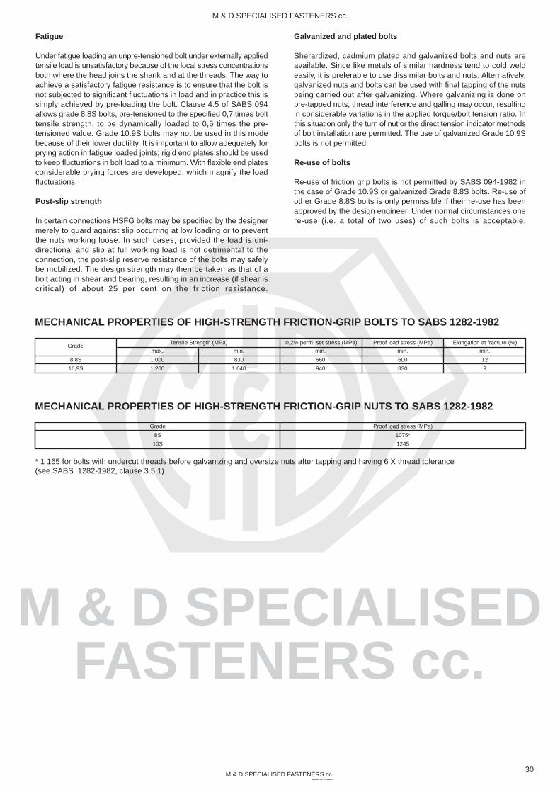
M & D SPECIALISEDFASTENERS cc.
M & D SPECIALISED FASTENERS cc.REG NO. CK 87/21963/23
M & D SPECIALISED FASTENERS cc.
Fatigue
Under fatigue loading an unpre-tensioned bolt under externally appliedtensile load is unsatisfactory because of the local stress concentrationsboth where the head joins the shank and at the threads. The way toachieve a satisfactory fatigue resistance is to ensure that the bolt isnot subjected to significant fluctuations in load and in practice this issimply achieved by pre-loading the bolt. Clause 4.5 of SABS 094allows grade 8.8S bolts, pre-tensioned to the specified 0,7 times bolttensile strength, to be dynamically loaded to 0,5 times the pre-tensioned value. Grade 10.9S bolts may not be used in this modebecause of their lower ductility. It is important to allow adequately forprying action in fatigue loaded joints; rigid end plates should be usedto keep fluctuations in bolt load to a minimum. With flexible end platesconsiderable prying forces are developed, which magnify the loadfluctuations.
Post-slip strength
In certain connections HSFG bolts may be specified by the designermerely to guard against slip occurring at low loading or to preventthe nuts working loose. In such cases, provided the load is uni-directional and slip at full working load is not detrimental to theconnection, the post-slip reserve resistance of the bolts may safelybe mobilized. The design strength may then be taken as that of abolt acting in shear and bearing, resulting in an increase (if shear iscritical) of about 25 per cent on the friction resistance.
Galvanized and plated bolts
Sherardized, cadmium plated and galvanized bolts and nuts areavailable. Since like metals of similar hardness tend to cold weldeasily, it is preferable to use dissimilar bolts and nuts. Alternatively,galvanized nuts and bolts can be used with final tapping of the nutsbeing carried out after galvanizing. Where galvanizing is done onpre-tapped nuts, thread interference and galling may occur, resultingin considerable variations in the applied torque/bolt tension ratio. Inthis situation only the turn of nut or the direct tension indicator methodsof bolt installation are permitted. The use of galvanized Grade 10.9Sbolts is not permitted.
Re-use of bolts
Re-use of friction grip bolts is not permitted by SABS 094-1982 inthe case of Grade 10.9S or galvanized Grade 8.8S bolts. Re-use ofother Grade 8.8S bolts is only permissible if their re-use has beenapproved by the design engineer. Under normal circumstances onere-use (i.e. a total of two uses) of such bolts is acceptable.
30
MECHANICAL PROPERTIES OF HIGH-STRENGTH FRICTION-GRIP BOLTS TO SABS 1282-1982
8,8S
10,9S
GradeTensile Strength (MPa) 0,2% perm. set stress (MPa) Proof load stress (MPa) Elongation at fracture (%)
max.
1 000
1 200
min.
830
1 040
min.
660
940
min.
600
830
min.
12
9
MECHANICAL PROPERTIES OF HIGH-STRENGTH FRICTION-GRIP NUTS TO SABS 1282-1982
Grade
8S
10S
Proof load stress (MPa)
1075*
1245
* 1 165 for bolts with undercut threads before galvanizing and oversize nuts after tapping and having 6 X thread tolerance(see SABS 1282-1982, clause 3.5.1)

M & D SPECIALISEDFASTENERS cc.
M & D SPECIALISED FASTENERS cc.REG NO. CK 87/21963/23
M & D SPECIALISED FASTENERS cc.
Notes on Tightening Torque
The importance of correct bolt tightening cannot be over emphasised.Determining the correct torque can however present problems.
Approximately 90% of the applied torque is employed in overcomingfriction, 50% at the bearing face of the nut and 40% between themating threads. It can therefore be seen that only something in orderof 10% effort is employed inducing axial load in the bolt.
Unfortunately, because of the variations in the frictional conditions,torque figures can give widely varying bolt tensions. The mainprecaution that can be taken is to calibrate the torque wrench foreach batch of bolts. It is recognised however, that in many cases thisis impracticable and for the majority of cases, the figures given in thetable overleaf may be taken as a useful guide.
The torque figures quoted are approximate figures and are applicableto fasteners in the self colour condition only.
They do not take into account the effect of plated finishes, speciallubricants or the effect of hard and smooth mating surfaces such ashardened washers etc.
The torque figures quoted have been based on a theoretical bolt loadequal to 85% of the proof load of the bolting material.
For bolt loads and diameters not shown in the chart the followingformula can be used:
31
Where K = FRICTIONAL FACTOR and can vary from less than 0,1to in excess of 0,3 depending on the type of plating if present, and the degree of lubrication. These torques maybe modified by multiplying the torque value by the appropriate CORRECTION FACTOR from the lubricationfactor tables on pages 27 and 31 as may be applicable.
During tightening, two stresses are applied to the bolt, torsion dueto friction between the threads and tension in stretching the bolt. Aftertightening however, only tension remains. In a rigid joint, if the bolttension exceeds the external tensile loads, the bolt will experienceno further stress and will not fail, providing of course that the correctbolts have been selected and the joints have been adequately
designed for the anticipated loads. It is important therefore that theclamping load in the joint is always greater than the external loading.
Correct pre-loading of the bolt resists the effects of fatigue. Providingthat the bolt pre-load is greater than an applied load, the fatigue lifeof the bolt will be infinite. The correct pre-load reduces the amplitudeof the stress change in the bolt to a safe value.
Always remember that the best method of keeping a nut on a boltis by proper tightening.
For technical details or advice on tightening problems, contact theTechnical Department of M & D Specialised Fasteners CC.
Torque (Nm) =
Plated Torque (Nm) = Calculated Torque (Nm) x friction correction factor
K x Bolt Load (N) x Nominal Bolt dia. (mm)
1000

M & D SPECIALISEDFASTENERS cc.
M & D SPECIALISED FASTENERS cc.REG NO. CK 87/21963/23
M & D SPECIALISED FASTENERS cc.
Zinc
1,00
1,20
0,90
0,65
0,55
Cadmium
0,80
1,35
1,20
0,70
0,65
A Guide to the Selection of Torque Values
It should be understood that the subject of torque tension loading isbeyond the scope of this manual. The information here supplied isan acceptable guide for normal conditions; for critical applications,however, further information and research will be necessary.
In preparing this guide to torque values, the following basic assumptionshave been made:
(a) bolts and nuts are new, standard finish, uncoated and not lubricated*
(b) the load will be 90% of the bolt yield strength(c) the coefficient of friction ( ) is 0,14
(d) the final tightening sequence is achieved smoothly and slowly,until the torque tool indicates full torque has been obtained.
* If lubrication has been applied to the bolt and/or the nut (otherthan the normal protective oil film), multiply the recommendedtorque by the appropriate factor shown in the table.
Example: Bolt and nut are both phosphated;required torque = torque recommended x 0.75.
32
LUBRICATION FACTOR
Sur
face
cond
ition
of n
ut
Self
Zinc
Cadmium
Phosphate and oil
Zinc with wax
1,00
1,15
0,85
0,70
0,60
Self
Surface condition of boltSurface condition of bolt
Phosphate
0,90
1,15
1,00
0,75
0,55
N.B. Antiseize lubricants can reduce torque required by approximately 20%
CONVERSION FACTORS
Torquelbf.ft x 1.36 = N mN m x 0.737 = lbf.ft
Flowl/s x 2.119 = cu.ft/mincu.ft/min x 0.472 = l/s
Forcelbf x 4.45 = NN x 0.225 = lbf
Powerhp x 0.746 = kW
kW = N m x rev/min
95555Pressurelbf/in x 0.069 = barbar x 14.504 = lbf/in
2
2
FORMULAE
Accepted formulae relating torque and tension, based on anytests, are:-
M = torque lbf.ftP = bolt tension lbfD = bolt dia. ins
M = torque N mP = bolt tension NewtonsD = bolt dia. mm
These formulae may be used for bolts outside the range of thetables.
P x D60M =
P x D5000M =
or for metric sizes:-
L2L1M2 = M1 x
FORMULA FORCALCULATING THE EFFECT OFTORQUE WRENCH EXTENSIONS
where L1 is the normal length and L2 is the extended length, M1 isthe set torque and M2 the actual torque applied to the nut.Example: Torque setting 100 Nm.L1 = 500 L2 = 650 (units of length not imporatnt, this is a ratio)
650500M2 = 100 x = 130 N m
TORQUE CONVERSION SCALE
L NORMAL LENGTH
L NORMAL LENGTH2
1
N m 0 10 20 30 40 50 60 70 80 90 100 110 120 130 140 150 160 170 180 190 200 210 220 230 240
0 1 2 3 4 5 6 7 8 9 10 11 12 13 14 15 16 17 18 19 20 21 22 23 24 25kpm
00
lbf.ftlb.in
10120
20240
30360
40480
50600
60720
70840
80960
901080
1001200
1101320
1201440
1301560
1401680
1501800
1601920
1702040
1802160

M & D SPECIALISEDFASTENERS cc.
M & D SPECIALISED FASTENERS cc.REG NO. CK 87/21963/23
M & D SPECIALISED FASTENERS cc.
N.m
0,52
1,88
4,31
8,48
14,71
35,30
70,61
122,60
299,10
578,6
1 000
2 010
3 491
5 609
Newtons
1 461
3 727
6 453
10 591
14 906
27 360
43 541
63 547
120 131
187 796
270 662
432 471
632 526
870 826
Newtons
863
2 206
3 825
6 257
8 836
16 230
25 791
37 657
71 196
111 305
160,338
255 952
374 612
515 827
N.m
0,12
0,44
1,00
1,96
3,43
8,24
16,7
28,4
69,6
135
230
466
814
1 304
Newtons
378
966
1 677
2 736
3 864
7 090
11 278
16 475
31 087
48 641
70 019
112 286
164 261
225 552
SUGGESTED MAXIMUM BOLT LOADS AND TORQUE VALUES (UNC THREADS)
33
UNC
in.
1/4
5/16
3/8
7/16
1/2
9/16
5/8
3/4
7/8
1
11/8
11/4
13/8
11/2
Newtons
4 379
7 344
10 951
15 065
20 244
26 075
32 452
49 781
67 157
88 221
111 007
142 135
168 641
206 578
N.m
5,43
11,2
19,9
31,9
48,8
70,4
97,4
178
279
418
593
837
1 096
1 456
lbf
984
1 650
2 461
3 386
4 551
5 861
7 295
11 191
15 097
19 832
24 955
31 953
37 911
46 440
lbf.ft
4,00
8,26
14,68
23,53
36,00
51,92
71,84
131,3
205,8
308,3
437,4
617,3
808,4
1 074
Quality P (Mild Steel) S T
Newtons
8 320
13 954
20 807
28 623
38 463
49 542
61 658
94 584
127 599
167 620
210 913
270 091
320 417
392 498
N.m
10,3
21,3
37,9
60,7
92,7
134
185
338
530
795
1 126
1 591
2 083
2 767
lbf
1 870
3 136
5 161
6 434
8 646
11 137
13 861
21 263
28 685
37 682
47 415
60 718
72 032
88 237
lbf.ft
7,60
15,71
27,95
44,77
68,37
98,83
136,45
249,3
391
586
830
1 173
1 536
2 041
Newtons
8 980
15 061
22 458
30 894
41 516
53 474
66 552
102 091
137 725
180 923
227 652
291 527
345 847
423 648
N.m
11,1
23,0
40,9
45,5
100
144
200
364
572
858
1 216
1 717
2 248
2 987
lbf
2 018
3 385
5 048
6 945
9 333
12 021
14 961
22 950
30 961
40 673
51 178
65 537
77 749
95 239
lbf.ft
8,19
16,96
30,17
48,31
73,76
106
1475
268,5
422
633
897
1 266
1 658
2 203
Width
across flats
in.
7/16
1/2
9/16
5/8
3/4
7/8
15/16
11/8
15/16
11/2
111/16
17/8
21/16
21/4
RECOMMENDED MAXIMUM BOLT LOADS AND TORQUE VALUES (UNF THREADS)
UNC
in.
1/4
5/16
3/8
7/16
1/2
9/16
5/8
3/4
7/8
1
11/8
11/4
13/8
11/2
Newtons
5 232
8 410
12 911
17 416
23 685
30 075
38 156
56 078
76 297
99 200
128 738
161 358
199 331
240 377
N.m
6,28
12,5
22,7
35,9
55,4
79,0
111
195
309
459
667
925
1 252
1 642
lbf
1 176
1 891
2 903
3 915
5 325
6 761
8 578
12 607
17 152
22 301
28 941
36 275
44 811
54 039
lbf.ft
4,63
9,22
16,74
26,5
40,9
58,3
81,9
144
228
339
492
682
923
1 211
Quality P (Mild Steel) S T
Newtons
9 941
15 979
24 531
33 091
45 002
57 143
72 496
106 549
144 965
188 480
244 602
306 580
378 728
456 717
N.m
11,9
23,8
43,2
68,2
105
150
210
370
587
873
1 267
1 757
2 378
3 119
lbf
2 234
3 592
5 514
7 439
10 116
12 846
16 297
23 953
32 589
42 371
54 988
68 921
85 141
102 673
lbf.ft
8,78
17,55
31,9
50,3
77,4
111
155
273
433
644
934
1 296
1 754
2 300
Newtons
10 730
17 247
26 478
35 717
48 574
61 678
78 250
115 005
156 470
203 439
264 015
330 911
408 786
492 965
N.m
12,9
25,7
46,6
73,6
114
162
227
399
634
942
1 368
1 896
2 567
3 367
lbf
2 412
3 877
5 952
8 029
10 919
13 865
17 591
25 854
35 175
45 734
59 352
74 391
91 898
110 822
lbf.ft
9,51
18,96
34,4
54,3
84,0
119
167
294
468
695
1 009
1 398
1 893
2 482
Width
across flats
in.
7/16
1/2
9/16
5/8
3/4
7/8
15/16
11/8
15/16
11/2
111/16
17/8
21/16
21/4
RECOMMENDED MAXIMUM BOLT LOADS AND TORQUE VALUES (METRIC COARSE THREADS)
mm
2
3
4
5
6
8
10
12
16
20
24
30
36
42
Newtons
284
726
1 255
2 059
2 903
5 315
8 473
12 356
23 340
36 481
52 563
84 043
123 073
169 164
N.m
0,16
0,59
1,34
2,65
4,51
10,79
21,57
38,25
93,16
180
308,9
622,7
1 089
1 746
3.6
Newtons
731
1 863
3 226
5 286
7 453
13 680
21 771
31 773
60 016
93 849
135 331
215 745
316 753
435 413
N.m
0,31
1,13
2,60
5,10
8,73
21,57
42,17
73,55
178,50
384,1
598,2
1 206
2 099
3 364
N.m
0,37
1,34
3,04
6,03
10,30
25,50
50,01
87,28
210,80
411,9
711,0
1 422
2 481
3 991
Newtons
1 216
3 109
5 374
8 806
12 405
22 751
36 284
52 956
100 027
156 415
225,552
359 902
527 595
725 688
N.m
0,63
2,26
5,15
10,20
17,65
42,17
85,32
147,10
357,90
696,3
1 196
2 403
4 197
6 727
Width
across flats
mm
4
5,5
7
8-9
10
13-14
15-17
19-21
24-26
30
36
46
55
65
5.6 6.9 8.8 10.9 12.9
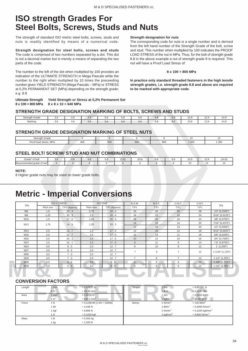
M & D SPECIALISEDFASTENERS cc.
M & D SPECIALISED FASTENERS cc.REG NO. CK 87/21963/23
M & D SPECIALISED FASTENERS cc.
Metric - Imperial ConversionsU.N.F.
T.P.I.
28
24
24
20
20
18
18
16
14
12
12
12
12
ISO COARSEDia.
1/4” (0,2500”)
5/16” (0,3125”)
3/8” (0,3750”)
7/16” (0,4375”)
1/2” (0,5000”)
9/16” (0,5625”)
5/8” (0,6250”)
3/4” (0,7500”)
7.8” (0,8750”)
1” (1,000”)
1-1/4” (1,250”)
1-3/8” (1,375”)
1-1/2” (1,500”)
B.S.W.
T.P.I.
20
18
16
14
12
12
11
10
9
8
7
6
6
B.S.F.
T.P.I.
26
22
20
18
16
16
14
12
11
10
9
8
8
M6
M8
M10
M14
M16
M20
M22
M24
M27
M30
M33
M36
M39
T.P.I (Approx)
25 . 4
20 . 3
17 . 0
12 . 7
12 . 7
10 . 1
10 . 1
8 . 5
8 . 5
7 . 3
7 . 3
6 . 4
6 . 4
Pitch mm
0,75
1,0
1,25
1,5
1,5
1,5
1,5
2,0
2,0
2,0
2,0
3,0
3,0
T.P.I (Approx)
34 . 0
25 . 4
20 . 3
17 . 0
17 . 0
17 . 0
17 . 0
12 . 7
12 . 7
12 . 7
12 . 7
8 . 5
8 . 5
U.N.C.
T.P.I.
20
18
16
14
13
12
11
10
9
8
7
6
6
Pitch mm
1,0
1,25
1,5
2,0
2,0
2,5
2,5
3,0
3,0
3,5
3,5
4,0
4,0
Strength Grade
Marking
ISO strength Grades ForSteel Bolts, Screws, Studs and NutsThe strength of standard ISO metric steel bolts, screws, studs andnuts is readily identified by means of a numerical code.
Strength designation for steel bolts, screws and studsThe code is comprised of two numbers separated by a dot. This dotis not a decimal marker but is merely a means of separating the twoparts of the code.
The number to the left of the dot when multiplied by 100 provides anindication of the ULTIMATE STRENGTH in Mega Pascals while thenumber to the right when multiplied by 10 times the preceedingnumber gives YIELD STRENGTH (Mega Pascals – MPa) or STRESSat 0,2% PERMANENT SET (MPa) depending on the strength grade;e.g. 8.8
Strength designation for nutsThe corresponding code for nuts is a single number and is derivedfrom the left hand number of the Strength Grade of the bolt, screwand stud. This number when multiplied by 100 indicates the PROOFLOAD STRESS of the nut in MPa. Thus, for the bolt of strength grade8.8 in the above example a nut of strength grade 8 is required. Thisnut will have a Proof Load Stress of:
8 x 100 = 800 MPa
In practice only standard threaded fasteners in the high tensilestrength grades, i.e. strength grade 8.8 and above are requiredto be marked with appropriate code.
34
STRENGTH GRADE DESIGNATION MARKING OF BOLTS, SCREWS AND STUDS
Ultimate Strength8 x 100 = 800 MPa
Yield Strength or Stress at 0,2% Permanent Set8 x 8 x 10 = 640 MPa
3.6
3,6
4.6
4,6
4.8
4,8
5.6
5,6
5.8
5,8
6.6
6,6
6.8
6,8
8.8
8,8
10.9
10,9
12.9
12,9
14.9
14,9
Strength Grade
Proof load stress, MPa
STRENGTH GRADE DESIGNATION MARKING OF STEEL NUTS4
400
5
500
6
600
8
800
10
1 000
12
1 200
Grade* of bolt
Recommended grade of nut*
STEEL BOLT/ SCREW/ STUD AND NUT COMBINATIONS3,6
4
4,6
4
4,8
4
5,6
5
(5,8)
5
(6,6)
6
6,8
6
8,8
8
10,9
10
12,9
12
(14,9)
14
NOTE:8 Higher grade nuts may be used on lower grade bolts.
M12 1,75
ISO FINE
14 . 5 1,25 20 . 3
Dia.
7 9 7 1-1/18” (1,125”)
Length
Area
Force
Mass
CONVERSION FACTORS1 mm
1 in
1 mm
1 in
1 N
1 lbf
1 kgf
1 N
1 lb
1 kg
= 0,03937 in
= 25,40 mm
= 0,0016 in
= 645,2 mm
= 0,2248 lbf (1 kN = 1000N)
= 4,448 N
= 9,806 N
= 0,1020 kgf
= 0,454 kg
= 2,205 lb
Torque
Stress
1 Nm
1 lb in
1 Nm
1 kgfm
1 N/mm
1 lbf/in
1 N/mm
1 kgf/mm
= 8,851lbf in
= 0,1130 Nm
= 0,1020 kgfm
= 86,80 lbf in
= 145 lbf/in
= 0,0069 N/mm
= 0,1020 kgf/mm
= 9,806 N/mm
2
2 2
2
2
2
2
2
2
2
2
2
12
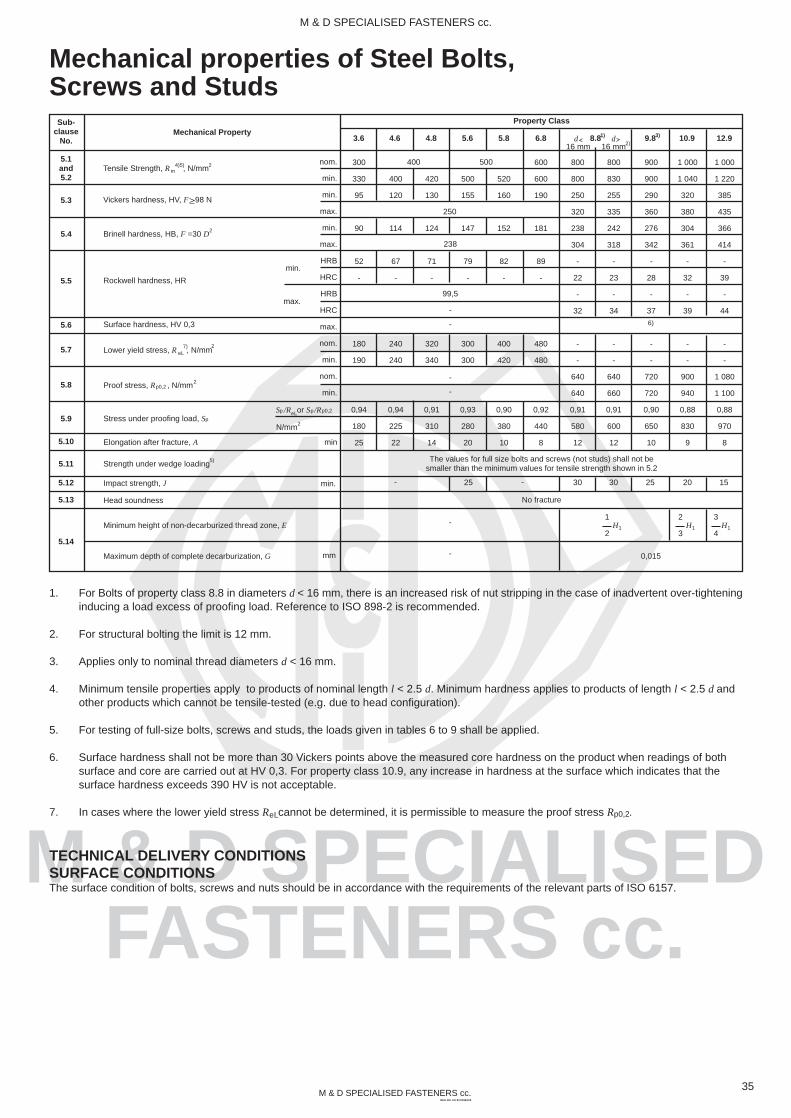
M & D SPECIALISEDFASTENERS cc.
M & D SPECIALISED FASTENERS cc.REG NO. CK 87/21963/23
M & D SPECIALISED FASTENERS cc.
1. For Bolts of property class 8.8 in diameters d < 16 mm, there is an increased risk of nut stripping in the case of inadvertent over-tighteninginducing a load excess of proofing load. Reference to ISO 898-2 is recommended.
2. For structural bolting the limit is 12 mm.
3. Applies only to nominal thread diameters d < 16 mm.
4. Minimum tensile properties apply to products of nominal length l < 2.5 d. Minimum hardness applies to products of length l < 2.5 d and other products which cannot be tensile-tested (e.g. due to head configuration).
5. For testing of full-size bolts, screws and studs, the loads given in tables 6 to 9 shall be applied.
6. Surface hardness shall not be more than 30 Vickers points above the measured core hardness on the product when readings of both surface and core are carried out at HV 0,3. For property class 10.9, any increase in hardness at the surface which indicates that the surface hardness exceeds 390 HV is not acceptable.
7. In cases where the lower yield stress R cannot be determined, it is permissible to measure the proof stress R .
TECHNICAL DELIVERY CONDITIONSSURFACE CONDITIONSThe surface condition of bolts, screws and nuts should be in accordance with the requirements of the relevant parts of ISO 6157.
400
120
114
67
-
240
240
0,94
225
22
420
130
124
71
-
320
340
0,91
310
14
500
155
147
79
-
300
300
0,93
280
20
520
160
152
82
-
400
420
0,90
380
10
600
600
190
181
89
-
480
480
0,92
440
8
800
800
250
320
238
304
-
22
-
32
-
-
640
640
0,91
580
12
30 30-
Mechanical properties of Steel Bolts,Screws and Studs
Mechanical PropertySub-
clauseNo.
5.1and5.2
5.3
5.4
5.5
5.6
5.7
5.8
5.9
5.10
5.11
5.12
5.13
5.14
Tensile Strength, R , N/mmm4)5) 2
Vickers hardness, HV, F 98 N
Brinell hardness, HB, F =30 D2
Rockwell hardness, HR
Surface hardness, HV 0,3
Lower yield stress, R , N/mm2
eL7)
Proof stress, R , N/mmp0,22
Stress under proofing load, Sp
Elongation after fracture, A
Strength under wedge loading5)
Impact strength, J
Head soundness
Minimum height of non-decarburized thread zone, E
Maximum depth of complete decarburization, G
nom.
min.
min.
max.
min.
max.
HRB
HRC
HRB
HRC
max.
nom.
min.
nom.
min.
min
N/mm
S /R or S /Rp p p0,2eL
2
Property Class
300
330
95
90
52
-
180
190
0,94
180
25
min.
mm
800
830
255
335
242
318
-
23
-
34
-
-
640
660
0,91
600
12
900
900
290
360
276
342
-
28
-
37
-
-
720
720
0,90
650
10
1 000
1 040
320
380
304
361
-
32
-
39
-
-
900
940
0,88
830
9
1 000
1 220
385
435
366
414
-
39
-
44
-
-
1 080
1 100
0,88
970
8
3.6 4.6 4.8 5.6 5.8 6.8 9.8 10.9 12.98.81) 3)
16 mm 16 mm2)d d
400 500
250
238
99,5
-
-
-
-
The values for full size bolts and screws (not studs) shall not besmaller than the minimum values for tensile strength shown in 5.2
-
No fracture
-
- 0,015
1
2H1
2
3H1
3
4H1
min.
max.
25 25 20 15
p0,2eL
35
6)

M & D SPECIALISEDFASTENERS cc.
M & D SPECIALISED FASTENERS cc.REG NO. CK 87/21963/23
M & D SPECIALISED FASTENERS cc.
3
(3.6)
3,6
6,5
10,4
15,1
20,7
28,2
34,5
44,1
54,5
63
82
100
124
147
175
201
234
264
316
365
424
482
550
Proof load Properties for ISO MetricHexagon Steel Nuts (Kilo Newton Values)
6
6
3 000
4 050
5 250
8 500
12 000
17 300
22 000
35 000
50 500
69 000
94 000
115 000
147 000
182 000
212 000
276 000
336 000
416 000
490 000
585 000
5
5
2 500
3 400
4 400
7 100
10 000
14 500
18 300
29 000
42 100
57 500
78 500
96 000
122 000
151 000
176 000
230 000
280 000
347 000
408 000
488 000
4
4
-
-
-
-
-
-
-
-
-
-
-
76 800
98 000
121 000
141 000
184 000
224 000
277 000
327 000
390 000
36
1
Nominal
thread diameter
mm
M3
M3,5
M4
M5
M6
M7
M8
M10
M12
M14
M16
M18
M20
M22
M24
M27
M30
M33
M36
M39
2
Nominal Stress
area of test mandreal
As, mm
5,03
6,78
8,78
14,2
20,1
28,9
36,6
58
84,3
115
157
192
245
303
353
459
561
694
817
976
8
8
4 000
5 400
7 000
11 400
16 000
23 000
29 000
46 000
67 000
92 000
126 000
154 000
196 000
242 000
282 000
367 000
448 000
555 000
653 000
780 000
10
10
5 000
6 800
8 750
14 200
20 000
29 000
36 500
58 000
84 000
115 000
157 000
192 000
245 000
303 000
353 000
459 000
561 000
694 000
817 000
976 000
12
12
6 000
8 150
10 500
17 000
24 000
34 700
43 000
69 500
100 000
138 000
188 000
230 000
294 000
364 000
423 000
550 000
673 000
833 000
980 000
1170 000
Grade
Proof load, kN
Proof load Properties for ISO Metric HexagonSteel Bolts and Screws (Kilo Newton Values)
1
Nominal size
of bolt or screw
mm
M6
M8
M10
M12
(M14)
M16
(M18)
M20
(M22)
M24
(M27)
M30
(M33)
M36
(M39)
M42
(M45)
M48
(M52)
M56
(M60)
M64
(M68)
Grade
Proof load, kN
2
Tensile stress
area
mm
20,1
36,6
58,0
84,3
115,0
157,0
192,0
245,0
303,0
353,0
459,0
561,0
694,0
817,0
976,0
1120,0
1300,0
1470,0
1760,0
2030,0
2360,0
2680,0
3060,0
4
4.6
4,5
8,2
13,0
18,9
25,8
35,3
43,2
55,1
68,1
79
103
126
156
183
219
252
292
330
396
456
531
603
688
5
(4.8)
5,8
10,6
16,8
24,4
33,3
45,5
55,6
71,0
87,8
102
133
162
201
236
283
324
377
426
510
588
684
777
887
6
5.6
7,3
10,2
16,2
23,6
32,2
43,9
53,7
68,6
84,8
98
128
157
194
228
273
313
364
411
492
568
660
750
856
7
(5.8)
6,8
13,3
21,1
30,7
41,9
57,3
70,0
89,4
110,5
128
167
204
253
298
356
408
474
536
642
740
861
978
1116
8
(6.6)
8,8
16,1
19,7
28,6
39,1
53,3
65,2
83,3
103,0
120
156
190
235
277
331
380
442
499
598
690
802
911
1040
9
6.8
11,6
21,2
25,5
37,0
50,6
69,8
84,4
107,8
133,3
155
201
246
305
359
429
492
572
646
774
893
1038
1179
1340
10
8.8
15,8
28,9
33,6
48,8
66,7
91,0
111,3
142,1
175,7
204
266
325
402
473
566
649
754
852
1020
1177
1368
1554
1774
11
10.9
19,0
34,7
45,8
66,5
90,8
124,0
151,6
193,5
239,3
278
362
443
548
645
771
884
1027
1161
1390
1603
1864
2117
2417
12
12.9
55,1
80,0
109,2
149,1
182,4
232,7
287,8
335
432
532
659
776
927
1064
1235
1396
1672
1928
2242
2546
2907
2
2

M & D SPECIALISEDFASTENERS cc.
M & D SPECIALISED FASTENERS cc.REG NO. CK 87/21963/23
M & D SPECIALISED FASTENERS cc.
2-1/2”
248
335
860
56
730
47
4”
223
310
790
51
660
43
B7
BS1506-6221A
ASTM. A193
Grade B7
0,38-0,48
0,20-0,35
0,75-1,00
0,80-1,10
0,15-0,30
-
-
0,04 max.
0,04 max.
14
54
40
-
-
2H
UNF
ton
2,024
3,228
4,873
6,589
8,869
11,28
14,19
20,63
28,21
36,68
Mechanical Properties for Unified Nuts
UNF
ton
1,840
2,935
4,430
5,990
8,060
10,25
12,90
18,75
25,65
33,35
UNC
ton
1,782
2,926
4,423
5,929
7,911
10,12
12,60
18,59
25,68
33,67
UNF
in
0,0368
0,0587
0,0886
0,1198
0,1612
0,205
0,258
0,375
0,513
0,667
UNC
in
0,0324
0,0532
0,0786
0,1078
0,1438
0,184
0,229
0,338
0,467
0,612
UNC
ton
1,620
2,660
3,930
5,390
7,190
9,200
11,45
16,90
23,35
30,60
UNF
ton
1,398
2,230
3,367
4,552
6,127
7,791
9,804
14,25
19,49
25,34
-
-
-
-
-
-
Mechanical Properties forUnified Bolts and Set Screws
UNC
ton
1,328
2,181
3,222
4,420
5,896
7,544
9,389
13,86
19,14
25,09
31,61
40,10
47,80
58,15
78,72
103,3
Grade S
Proof stress 38 tonf/in
UNF
in
0,0368
0,0587
0,0886
0,1198
0,1612
0,205
0,258
0,375
0,513
0,667
-
-
-
-
-
-
Nominal
size of bolt
or screw
in
1/4
5/16
3/8
7/16
1/2
9/16
5/8
3/4
7/8
1
11/8
11/4
13/8
11/2
13/4
2
37
Alloy Steel Studbolts and Nuts to B.S. 4882,and ASTM A193/ A194
UNC
in
0,0324
0,0532
0,0786
0,1078
0,1438
0,184
0,229
0,338
0,467
0,612
0,771
0,978
1,166
1,148
1,92
2,53
UNC
ton
1,231
2,021
2,986
4,097
5,466
6,992
8,702
12,84
17,74
23,26
29,30
37,16
44,31
53,89
72,97
95,76
UNF
ton
1,509
2,406
3,633
4,911
6,610
8,407
10,58
15,38
21,03
27,35
-
-
-
-
-
-
in
1/4
5/16
3/8
7/16
1/2
9/16
5/8
3/4
7/8
1
StressGrade T
Proof stress 41 tont/inProof Load
2 2
2 2
Stress area x proof stress = proof load
Stress area x min. tensile strength of bolt = proof loadof nuts
Nominal
size of nut
Nominal
size of nut
Stress area
of bolts
Grade 1 nuts Grade 3 nuts
For use with boltsof grade S
For use with boltsof grade T
Min. tensile of gradeS bolts 50 tonf/in
Min. tensile of gradeT bolts 50 tonf/in
2 2
22
CHEMICAL ANALYSIS & MECHANICAL PROPERTIES - STUDBOLTS & NUTSSTUDBOLTS
Grade of Bolting & Marking Symbol
Recommended Bolting Temperature Range
B.S. Material Specification
American Specification
Chemical Analysis
Mechanical Properties
Grade of Nut & Marking symbol
Recommended Temperature Range
B.S. Material Specification
American Specification
Chemical Analysis
Mechanical Properties
2H
BS. 1506-162
ASTM. A194
Grade 2H
0,4 min
-
-
-
-
-
0,05 max.
0,04 max.
248-352
Carbon
Silicon
Manganese
Chronium
Molybdenum
Vanadium
Nickel
Sulphur
Phosphorus
Limiting Ruling Section
Brinell Hardness
Minimum Tensile Strength
Minimum Yield Strength
0,2% Proof Stress
Minimum Elongation
Minimum Izod Impact Value
Charpy V Notch Low Temperature
Impact Value at - 100 C
Recommended nut grade
%
%
%
%
%
%
%
%
%
Min.
Max.
N/mm
Tonf/in
N/mm
Tonf/in
%
J
ft lb.f
J
ft lb.f
Carbon
Silicon
Manganese
Chromium
Molybdenum
Nickel
Sulphur
Phosphorus
Brinell Hardness
%
%
%
%
%
%
%
%
L7
BS1506-621A
BS1510-LT100
ASTM. A320
Grade L7
0,38-0,48
0,20-0,35
0,75-1,00
0,80-1,10
0,15-0,30
-
-
0,04 max.
0,04 max.
14
54
40
20
15
L4
B16
BS1506-661
ASTM. A193
Grade B16
0,36-0,44
0,20-0,35
0,45-0,70
0,80-1,15
0,50-0,65
0,25-0,35
-
0,04 max.
0,04 max.
4”
248
335
860
56
730
47
13
47
35
-
-
4
B8
BS1506-801B
ASTM. A193
Grade B8
0,08 max.
1,0 max.
2,0 max.
18,0-20,0
-
-
8,0-11,0
0,03 max.
0,045 max.
-
-
183
540
35
210
13,5
35
-
-
-
-
8
B8M
BS1506-845
ASTM. A193
Grade B8M
0,08 max.
1,0 max.
2,0 max.
16,0-18,0
2,5-3,0
-
10,0-13,0
0,03 max.
0,045 max.
-
-
183
540
35
210
13,5
35
-
-
-
-
8M
L4
BS. 1506-240
ASTM. A194
Grade 4
0,4-0,5
0,2-0,35
0,7-0,9
-
0,2-0,35
-
0,04 max.
0,035 max.
248-352
4
BS. 1506-240
ASTM. A194
Grade 4
0,4-0,5
0,2-0,35
0,7-0,9
-
0,2-0,35
-
0,04 max.
0,035 max.
248-352
8
BS. 1506-810B
ASTM. A194
Grade 8
0,08 max.
0,1 max.
0,2 max.
18,0-20,0
-
8,0-11,0
0,03 max.
0,045 max.
183 max.
8M
BS. 1506-845
ASTM. A194
Grade 8M
0,08 max.
0,1 max.
0,2 max.
16,0-18,0
2,5-3,0
10,0-13,0
0,03 max.
0,045 max.
183 max.
Min.
-100 C
Max.
400 C
Min.
-100 C
Max.
400 C
Min.
0 C
Max.
520 C
Min.
-250 C
Max.
575 C
Min.
-250 C
Max.
600 C
Min.
-250 C
Max.
600 C
Min.
-250 C
Max.
575 C
Min.
-100 C
Max.
520 C
Min.
-100 C
Max.
520 C
Min.
0 C
Max.
450 C
NUTS
2
2
2
2
2-1/2”
248
335
860
56
730
47
4”
223
310
790
51
660
43

M & D SPECIALISEDFASTENERS cc.
M & D SPECIALISED FASTENERS cc.REG NO. CK 87/21963/23
M & D SPECIALISED FASTENERS cc.
ASTM.A307 Gr A
General Engineering
Grades
10,9
38
Imperial Strength Grades for Steel Bolts, Screws,Studs and nuts
Thread
BS 1768
UNC
and
UNF
Strength grade
of bolt
A B and P
S
T
V and X
Recommended grade
of nut
O
I
3
5
Nut proof
load equivalent
Minimum tensile strength of Grade P bolts
Minimum tensile strength of Grade S bolts
Minimum tensile strength of Grade T bolts
Minimum tensile strength of Grade X bolts
Comparisons of Various Grades of Bolts,Screws and Studs
Min U.T.S
MPa
(N/mm )
I.S.O
Strength Grades
BRITISH
B.S. Grades
AMERICAN
S.A.E Grades
Min U.T.S.
tsi
4,6 & 4,8
5,6 & 5,8
6,6 & 6,8
8,8
12,9
400
500
600
700
800
900
1 000
1 100
1 200
1 300
80
75
70
65
60
55
50
45
40
35
30
25
A & B (M.S.-28 tsi)
P (35 tsi)
R (45 tsi)
S (50 tsi)
T (55 tsi)
V (65 tsi)
X (75 tsi)
8 (67 tsi)
5 (1/4”-1” -53.6 tsi)
5 (1-1/8”1-1/2” -46.9 tsi)
2 (1/4”-3/4” -33 tsi)
2 (7/8”-1-1/2” -26.8 tsi)1 (1/4”-1-1/2” -26.8 tsi)
ASTM.A307 Gr B
(Both 26.8 tsi)
ASTM.A325 (1-1/8”-1-1/2”)
ASTM.A325 (7/8”-1”)
ASTM.A325 (1/2”5/8”3/4”)
ASTM.A490
ASTM.A490 (2-1/2”-4”)

M & D SPECIALISEDFASTENERS cc.
M & D SPECIALISED FASTENERS cc.REG NO. CK 87/21963/23
M & D SPECIALISED FASTENERS cc.
Corrosion Protection
INTRODUCTION
There are many ways of fastening one component to another andthe need for this implies the need for them to remain fastened together.There is also the additional requirement that the parts may, from timeto time, have to be disassembled e.g. for maintenance.
Corrosion mainly affects the durability of fasteners, (i.e. their lastingstrength, appearance and ease of dismantling) and may be causedby exposure to a particular environment during service.
Many types of environment are encountered. For example, atmosphericconditions may involve exposure to salt spray near the sea, sulphurdioxide, sulphuric acid and high concentration of solids in industrialregions, high concentrations of airborne contaminants near chemicalplants, high temperatures and humidity in tropical regions and extremecold in others.
39
USE OF RESISTANT COATINGS OR FINISHES
Finish
Electrodeposited zinc
Electrodepositedcadmium
Electrodepositednickel and nickelplus chromium
Hot dip zinc(galvanising)
Dillision coated zinc(sheradizing)
Phosphate coating
Chromate passivation(for zinc andcadmium coatings)
Anodising (foraluminium alloys)
Organic finishesplastic dip coatingsresins and lacquers
Specification
BS 3382 Part 2
BS 1706DTD 903C
BS 3382 Part 1
BS 1706DTD 904C
BS 3382 Parts 3 and 4
BS 1224 : 1965
SABS 763(Related spec. BS 729 Pt. 1)
BS 729 Part 2
BS 3189DEF 29
DEF 130Included in BS 3382Parts 1 and 2
DTD 910CBS 1615
Typical application
Usually bright finish on steel screws. Used forshort term protection of steel fasteners.Satisfactory for standard threads.
For all parts requiring heavy coatings up to38,1 microns deposit thickness.
Usually semi-bright finish on steel screws.Satisfactory for standard threads.
For all parts requiring heavier coatings upto 10,6 microns cadmium.
On to steel and copper alloy screws.Satisfactory short term protection andbright finish on standard threads.
For all parts requiring protective and decorativefinish. Different grades provide for long terminterior and outdoor performance.
Heavy zinc deposits 38,1-76,2 microns onsteel for long term outdoor protection.Uneven coating unsuitable for many smallthreaded parts.
Dull grey protective finish equivalent toapproximately 25,4 microns zinc. Fairly evenfinishon threads. Develops rusty colour on initialweathering.
Dark, almost black, finish suitable for shortterm protection of all steel threaded parts.Coating must be sealed with oil, wax orlacquer to be effective.
Provides an improvement on the performanceof normal zinc and cadmium finishes, usuallygreen-brown in colour.
Provides additional corrosion protection foraluminium, but the coating must be sealedwith oil or lanolin to prevent screw threadseizure.
Applied over BS 3382 Zn coatings for bestperformance. Wide choice of finishes,colours, and performance.
Choice of coatingThe choice of coating to use must be made in relation to the environment, the service life required, the type of fastener and the acceptable cost.

M & D SPECIALISEDFASTENERS cc.
M & D SPECIALISED FASTENERS cc.REG NO. CK 87/21963/23
M & D SPECIALISED FASTENERS cc.
Material
C Cr Ni Fe0,06 18 10 bal.Ti, Nb, S, Se are optional special additions to meetparticular requirements.
BS 970 Part 4 and PD 6290Code Nos. 303 S41, 304 S15, 305 S19, 321 S12, 347 S17BS 1506-801, 821 AISI types 302, 303, 304, 305, 321,347 BS 1750 (bolting)Grades B8, B8T, B8C, ASTM A193 and A194 (bolting)
Excellent resistance to atmospheric corrosion exceptsevere industrial and marine conditions.Oxidation resistance satisfactory for use up to 850 C.Resistance to nitric acid and other oxidizing chemicalsis excellent. Resistance to other mineral and organicacids is good within certain limits of temperature andconcentration.Generally unsuitable for solutions of hydrochloric acidand chlorides, particularly if evaporation at hightemperatures can occur. Free machining steels may havelower corrosion resistance than other types, in somecircumstances.
Non-magnetic except when heavily cold worked.Not hardenable by heat treatment but strengthenedgreatly by cold working. Special coatings can preventthread seizure at high temperatures.High strength and toughness at sub-zero temperatures downto -250 C.Significant stress relaxation above 575 C.
Chemical and civil engineering projects. Food processing,medical and brewing equipment and many domesticappliances. Fasteners for aluminum alloy, concrete,plastic, and plastic coated steel assemblies.Cryogenic equipment.Special purpose builing and masonry fixings.
Forged bolts, set screws, nuts, socket screws, machinescrews, rivets, self-tapping screws, woodscrews.Special fully machined products.
CHOICE OF FINISH (ZINC OR CADMIUM)
Both zinc and cadmium are commonly regarded as providing sacrificialprotection of iron and steel: that is to say, in a corrosive environmentthe zinc or cadmium corrodes and in so doing protects the steel fromcorrosion even if it should be exposed at pores or cracks or otherdiscontinuities in the coatings caused, for example, by mechanicaldamage.
Fortunately, sacrificial protection is only part of the story. Underconditions of atmospheric exposure or immersion in hard waters zincremains protective for prolonged periods because any discontinuitiesin the coating are sealed by deposit of carbonate which is laid downas a result of the sacrificial corrosion occurring. In soft watersdiscontinuities in the zinc cannot be sealed in this way and theprotection afforded to steel by a zinc coating is, therefore limited.Fortunately, the rate of corrosion of cadmium in soft waters is slowerthan that of zinc, which means that a longer life is normally obtained
for a cadmium plated steel article of equal deposit thickness.Furthermore, discontinuities in a cadmium coating can be sealed inchloride solutions by the formation of basic cadmium chloride oflimited solubility
Both zinc and cadmium do, of course, corrode in spite of this “healing”action at discontinuities, and the overall life of a coated steel article,therefore, depends on the thickness of the deposit. The onset ofattack can be delayed (and the overall life hence increased) to a verymarked degree by applying a chromate passivation treatment to thezinc or cadmium deposit.
Considered purely in terms of corrosion protection, zinc is normallyto be preferred to cadmium in all atmospheric conditions and underconditions of immersion in hard water. Cadmium is normally preferableto zinc under immersed conditions in soft waters and chloride-containing solutions. Cadmium also shows greater resistance tocorrosion by alkaline solutions.
40
MATERIALS FOR STAINLESS STEEL FASTENERS
PLATING STANDARD SCREW THREADSThe thickness of coatings which can be applied to standard screw threads is limited due to possibility of thread interference with similarly platedmating threads.
USE OF CORROSION RESISTANT MATERIALSThe most commonly used materials are stainless steels of which the most popular are the two austenitic grades 18/8 and 18/10/3.
Material
Typical composition
Relatedspecifications
Corrosion and heatresistingcharacteristics
Other specialfeatures
Typicalapplications
Fastenertypes
Austentic stainless steel (18/10/3 type)
C Cr Ni Mo Fe0,06 18 10 2,75 bal.
BS 970 Part 4 Code Nos. 316 S16BS 1506-845AISI type 316ASTM A193 and A194 bolting gradesB8M and 8M
Higher corrosion resistance than 18/8grade in many chemical environments,including contact with dilute sulphuricacid, and acetic acid over a wide rangeof temperature and concentration.Resistance to atmospheric staining andpitting in industrial and urban areas,and also suitable for marine conditions-except continuous immersion in sea water.Satisfactory oxidation resistance up to800 C.
As 18/8.
Significant stress relaxation above600 C.
Fasteners for boat deck fittings,chemical plant, swimming baths andvats. Fertiliser, rayon and sewagetreatment plant. Dairy equipment.Medical sterilizing equipment. Specialpurpose building and masonry fixings.
Forged bolts, set screws, machinescrews and nuts and special machinedor forged items.

M & D SPECIALISEDFASTENERS cc.
M & D SPECIALISED FASTENERS cc.REG NO. CK 87/21963/23
M & D SPECIALISED FASTENERS cc.
Materials for Stainless Steel Fasteners
From many available grades of stainless steel, two have been chosenfor Stainless Steel Fasteners. Their high corrosion resistance suitspractically every application.
COMPOSITION
Stainless Steel Fasteners are designated after the main constituentsof their alloys:
18-8Stainless steel with 18% chromium, 11% nickel.18-8-2Stainless steel with 18% chromium, 12% nickel, 2,3% molybdenum.
The designation of Stainless Steel Fasteners is therefore brief andeasily understood.
18 = content of chromium8 = content of nickel2 = content of molybdenum
Both steel grades today contain considerably higher amount ofalloying elements than shown on the marking. We maintain, however,the designation for Stainless Steel Fasteners which is well knownsince decades. Table 1 gives the material numbers for specificationsto DIN 17007, the short designations to DIN 17006, as well as theAmerican material numbers to AISI which are widely usedinternationally.
41
Properties
Material Designation
to DIN 17007
Short name to
DIN 17006
Material number to
AISI
Chemical
Composition %
Averages
to DIN 17440
Texture
TABLE 1 - COMPOSITION AND DESIGNATION18-8
Corrosion resistant
Weldable
A 2
X 5 CrNi 1911
(1,4303)
304/305
C 0,07
Cr 18,5
Ni 11,3
(1,4303)
Austenitic
18-8-2
Acid proof
Weldable
A 4
X 10 CrNiMoTi 1810
(1,4571)
316 Ti/316
C 0,10
Cr 17,5
Ni 12
Mo 2,3
Ti
(1,4571)
Austenitic
TENSILE STRENGTH, PROPERTY CLASSES(Hexagon Bolts and nuts)
DIN 267, part 11 comprises all agreements of international standardISO 3506 – 1979. The classification into three property classes hasbeen maintained concerning existing determinations. Requirementswithin the property classes though have partly been altered.
The marking has been changed adequate to the classification ofproperty classes. The last two figures show 1/10 of the minimumtensile strength in N/mm . The elongation is now specified in mm, notin % of the clamping length.
Standard is property class 70.
The mechanical property values of screws 18-8 (A2) and18-8-2 (A4) apply to standardised screws of length up to and inclusive8 x diameters in length under condition of room temperature. Thereis no length limitation for property class 50.
2

M & D SPECIALISEDFASTENERS cc.
M & D SPECIALISED FASTENERS cc.REG NO. CK 87/21963/23
M & D SPECIALISED FASTENERS cc.
M16
126
144
162
Property class 80
0,27
0,56
1,2
2,1
4,9
10,0
TABLE 3
50
70
80
Screws
A2
A4
42
TABLE 2
Grade
Nuts
Property class
M39
M20
M20 M30
M20
Diameter range
500
700
500
800
Tensilestrength
RN/mmmin.
210
450
250
600
Stress at 0,2%permanent strain
RN/mmmin.
0,6 d
0,4 d
0,4 d
0,3 d
Extension
A
mm
min.
Proof load
stress
S
N/mm
500
700
500
800
2m r 20
r2
1
BREAKING TORQUE (Slotted Machine Screws)
At this point again classification in three property classes has beenmade. The breaking torques are fixed on machine screws of threadM 1,6 to M 5. The testing is completed by determination of tensilestrength (minimum values see table 2).
Testing of the stress of 0,2% permanent strain and breaking extensionis being dropped with smaller screws M 1,6 to M 5.
All tensile stress values are varied under condition of testing whole screw relating to nominal tensile stress of the thread.
Minimum breaking torques (T ) for screws up to M 5 (A2 + A4).m
Minimum breaking torques in NmThread
size
M1,6
M2
M2,5
M3
M4
M5
Standard is property class 70.
Property class 50
0,15
0,3
0,6
1,1
2,7
5,5
Property class 70
0,2
0,4
0,9
1,6
3,8
7,8
PERMISSIBLE TORQUES(Hexagon Head Bolts and Set Screws)
The torques are valid for screws DIN 931/933, property class 70 undercondition of room temperature.
Because of the fact, that in practice many different frictions occur,torques for three different coefficients of friction figures were tabulated.
On top of that also other friction figures can occur, so that thosefigures named in table 4 can only be used as approximate values.Before final determination of torques a testing accordingly underpractical conditions is recommended.
Permissible torques for screws 18-8 (A2) and 18-8-2 (A4).
Torques for screws DIN 931/933 up to length inclusive 8 x diameters in length under condition of room temperature,standard property class 70.
TABLE 4Permissible torques in NmFriction
Figure
0,12
0,14
0,16
M5
3,7
4,2
4,7
M6
6,4
7,3
8,2
M8
15,3
17,5
19,6
M10
31
35
39
M12
52
60
67
M14
83
94
106
M18
174
199
225
M20
245
281
316
M22
182
209
236
M24
235
269
304
M27
342
392
443
M30
467
536
605
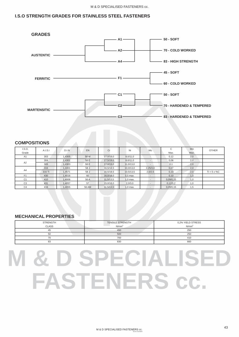
M & D SPECIALISEDFASTENERS cc.
M & D SPECIALISED FASTENERS cc.REG NO. CK 87/21963/23
M & D SPECIALISED FASTENERS cc.
303
304
305
316
316 Ti
430
410
431
416
43
COMPOSITIONSI.S.O.
Grade
A1
F1
C1
C3
C4
MECHANICAL PROPERTIESSTRENGTH
CLASS
45
50
70
83
TENSILE STRENGTH
N/mm
450
500
700
830
0,2% YIELD STRESS
N/mm
250
250
410
660
2 2
1,4305
1,4301
1,4303
1,4401
1,4571
1,4016
1,4006
1,4057
1,4055
58 M
58 E
58 E
58 J
58 J
60
56 A
57
56 AM
17,0/19,0
17,5/19,0
17,0/19,0
16,5/18,5
16,5/18,5
16,0/18,0
11,5/13,5
15,0/18,0
11,5/13,5
8,0/11,0
8,0/11,0
11,0/13,0
10,0/13,0
10,5/13,5
0,5 max.
1,0 max.
2,0/3,0
1,0 max.
-
-
-
2,25/3,0
2,0/2,5
-
-
-
-
C
Max.
0,12
0,06
0,1
0,07
0,10
0,10
0,09/0,15
0,12/0,2
0,09/0,15
Min
Max.
2,0
2,0
2,0
2,0
2,0
1,0
1,0
1,0
1,5
Ti = 5 x %C
A.I.S.I D.I.N EN Cr Ni Mo OTHER
I.S.O STRENGTH GRADES FOR STAINLESS STEEL FASTENERS
GRADES
AUSTENTIC
FERRITIC
MARTENSITIC
A1
A2
A4
F1
C1
C2
C3
50 - SOFT
70 - COLD WORKED
83 - HIGH STRENGTH
45 - SOFT
60 - COLD WORKED
50 - SOFT
70 - HARDENED & TEMPERED
83 - HARDENED & TEMPERED
A2
A4

M & D SPECIALISEDFASTENERS cc.
M & D SPECIALISED FASTENERS cc.REG NO. CK 87/21963/23
M & D SPECIALISED FASTENERS cc.
44
MATERIALS FOR SPECIAL APPLICATIONS
Due to the required product rationalization, considerably more fastenersof the steel grades A2 and A4 are used than of any other stainlessgrades. This development will continue in the future. For special
applications, however, fasteners of other high grade alloys are alsorequired. For such applications we process the following materials:
TABLE 5 - MATERIALS FOR SPECIAL APPLICATIONS
For extremely corrosive
environments
With Higher requirements for
mechanical strength but less
for corrosion resistance
For high long duration rupture
strength at temperatures above 540 C
For extreme operating conditions
For high ductility in cryogenic
applications
Acid-proof steels with even higher
contents of Chronium, Nickel and Molybdenum
Chromium steels with 13% or 17%
Chromium
High temperature steels
Titanium, Hastelloy, Monel, Inconel,
Nimonic and similar super alloys
Cold ductile steels
Both at the steel works and for fastener manufacture, certain minimum economic quantities are required. It is therefore recommended
to limit the use of fasteners in these special alloys to real necessity.
LONG TERM RUPTURE STRENGTH
The values in tables 2 and 3 were determined in short time tests.Such tests are adequate for most applications. In many cases, however,connected parts are for extended periods under mechanical stress.In these cases the long term rupture strength can be imported.
Long term rupture strength determines the resistance against creepand relaxation (reduction of the initial tension of fasteners due tocreep of the steel). Stainless steel fasteners show considerably lowercreep at high stress than normal steel fastener grades 4.6 and 5.6.
To avoid creeping under permanent stress, fasteners have to bediminished so that the technical elasticity limit is not exceeded (stressof 0,001% permanent strain). Therefore for the building industry 30%of the stress of 0.2% permanent strain shown in table 2 is spelled.For other applications 0,01% limit can be taken as 50% of the stressof 0,2% permanent strain. For accurate calculations a special testmay be required.
TABLE 6 - YIELD POINT AT ELEVATED TEMPERATURESC
% min
YIELD STRENGTH AT ELEVATED TEMPERATURES
Stainless Steel Fasteners 18-8 (A2) and 18-8-2 (A4) are used ascorrosion resistant and high temperature fasteners up to + 400 C. Table6 gives percentages of the stress of 0,2% permanent strain, given intable 2 for property class 2 which must be exceeded at the show elevated
temperatures. Fasteners of grade A4 , which contain the alloyingelement Molybdenum have a higher yield point at elevated temperaturethan fasteners of grade A2.
100
85
200
80
300
75
400
70

M & D SPECIALISEDFASTENERS cc.
M & D SPECIALISED FASTENERS cc.REG NO. CK 87/21963/23
M & D SPECIALISED FASTENERS cc.
UK
BS
-
304 S16
305 S19
321 S12
316 S16
320 S17
Sweden
SIS
-
2333
-
2337
2343
(2343)
USSR
Gost
-
08 CH 18 N 10
06 CH 18 N 11
12 CH 18 N 10 T
08 CH 17 N 12 M 2
10 CH 17 N 13 M 2 T
France
Afnor
-
Z 6 CN 18-10
-
Z 10 CN T 1810
Z 6 CND 18-12
Z 10 CND T 18-12
May stainless steel fasteners be safely connected with other materials?The following sections discuss some examples of such combinations
Aluminium
In the building industry stainless steel fasteners are frequently combinedwith aluminium alloys, because perfect appearance is maintained evenafter many years of exposure to industrial atmosphere and theconnections can easily be opened. These connections do not exhibitcontact corrosion because the surface of the aluminium alloy is coveredwith an electrochemically insulating layer of aluminium oxide.
Steel
Combining stainless steel fasteners with normal steel necessitatesperfect protection of the adjacent steel surfaces. A zinc plating forexample has to be free of pinholes. The same applies to all other layersof surface protection. Also, where machine parts of cast iron areconnected, whenever corrosion threatens the surface of the cast ironhas to be protected.
45
Copper and brass
Contact corrosion is not found when surface of the fasteners is smallcompared with the surrounding surface. Additional protection is,however, recommended.
Timber
Stainless steel fasteners do not corrode as long as the timber isinternally dry and only the surface becomes wet. Complete and extendedsoaking of the timber may cause crevice corrosion. Even under theseconditions stainless steel fasteners endure many times longer thanfasteners of non-alloyed steel.
Plastic
As with timber, corrosion depends on the local conditions. The use ofwashers of polyamide or PVC may, under certain condition, causecrevice corrosion. For example, in humid atmospheres or chlorinatedwater. These washers are therefore only recommended when exposureto humidity in infrequent. Plastic is easily deformed mechanically andtherefore tends to creep even at room temperature.
Stainless Steel Fasteners in ContactWith Other Materials
Exposure to different kinds of corrosive media which lead to rusting anddestruction requires the choice of the correct grade of stainless steel.There are ample possibilities for attack by humidity, water, industrialatmosphere, exhaust gas, soot, dust, maritime atmosphere, fog, rain,acids and alkalis which all may exist in isolation or combination. Fastenersused in lighting equipment on a coastal road are exposed to differentkinds of attack to those in a dish washer. But all requirements (with theexception of a very few exceptional conditions) are covered with oneof stainless steel grades 18-8 (A2) or 18-8-2 (A4).
Which steel for which exposure?
Weather
Atmospheric attack is frequently stronger than expected. Contaminationsand chemical attack contribute in most cases. Fasteners of low alloyedsteels are insufficiently rust proof. Four outdoor connections, stainlesssteel fasteners 18-8 (A2) are therefore recommended.
Humidity, Water
For domestic appliances, refrigerators, kitchen installations etc., fasteners18-8 (A2) are to be used. The rather irregular shape of fasteners is
prone to crevice corrosion, necessitating the use of stainless steel,more than the large and smooth surfaces of sinks, washing machinesand cases. For exposure to water and humidity in industrial application,stainless steel fasteners 18-8 (A2) are normally used.
This also applies to electrotechnical applications, paper mills or hydraulicengineering (locks, weirs, sluice gates). In particularly aggressiveconditions, for example exposure to sea or harbour water, stainlesssteel fasteners 18-8-2 (A4) are recommended.
Acids, alkalis
For many applications the steel 18-8 (A2) is sufficient, for dairies,breweries, filter plants, food- and chemical solutions, pharmaceuticalindustry, chemical cleaning, laboraties, photographic industry, soap-and washing powder industry and many other applications in thechemical industry.
For more aggressive media fasteners 18-8-2 (A4) need to be used.
A careful examination under operating conditions is frequently required.We wil l be pleased to help with advice and samples.
Data for Choosing 18-8 (A2)18-8-2 (A4) Stainless Steel Fasteners
TABLE 8
National Standards Comparison for Stainless Steel
Germany
No. according
to DIN 17440
1.4305
1.4301
1.4303
1.4541
1.4401
1.4571
Grade
ISO 3506
A1
A2
A4
Stainless Steel
Fastener
-
18-8
18-8-2
Italy
UNI
-
X 6 CN 1911
-
X 8 CN T 1810
X 8 CND 1712
X 8 CND T 1712
USA
AISA
(303 Se)
304
305
321
316
316 Ti
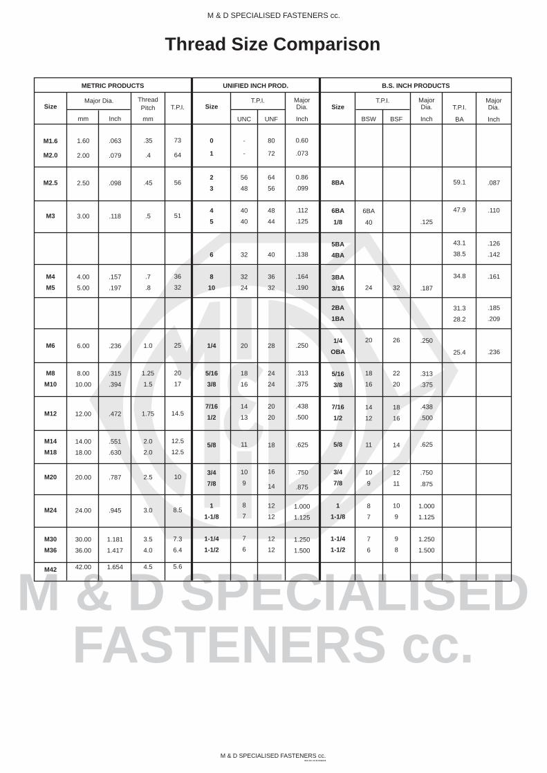
M & D SPECIALISEDFASTENERS cc.
M & D SPECIALISED FASTENERS cc.REG NO. CK 87/21963/23
M & D SPECIALISED FASTENERS cc.
Thread Size Comparison
Major Dia.
UNIFIED INCH PROD. B.S. INCH PRODUCTS
T.P.I. T.P.I.Size
M1.6
M2.0
M2.5
M3
M4
M5
M6
M8
M10
M12
M14
M18
M20
M24
M30
M36
M42
METRIC PRODUCTS
mm
1.60
2.00
2.50
3.00
4.00
5.00
6.00
8.00
10.00
12.00
14.00
18.00
20.00
24.00
30.00
36.00
42.00
Inch
.063
.079
.098
.118
.157
.197
.236
.315
.394
.472
.551
.630
.787
.945
1.181
1.417
1.654
ThreadPitch
mm
.35
.4
.45
.5
.7
.8
1.0
1.25
1.5
1.75
2.0
2.0
2.5
3.0
3.5
4.0
4.5
T.P.I.
73
64
56
51
36
32
25
20
17
14.5
12.5
12.5
10
8.5
7.3
6.4
5.6
Size
0
1
2
3
4
5
6
8
10
1/4
5/16
3/8
7/16
1/2
5/8
3/4
7/8
1
1-1/8
1-1/4
1-1/2
UNC
-
-
56
48
40
40
32
32
24
20
18
16
14
13
11
10
9
8
7
7
6
UNF
80
72
64
56
48
44
40
36
32
28
24
24
20
20
18
16
14
12
12
12
12
MajorDia.
Inch
0.60
.073
0.86
.099
.112
.125
.138
.164
.190
.250
.313
.375
.438
.500
.625
.750
.875
1.000
1.125
1.250
1.500
Size
8BA
6BA
1/8
5BA
4BA
3BA
3/16
2BA
1BA
1/4
OBA
5/16
3/8
7/16
1/2
5/8
3/4
7/8
1
1-1/8
1-1/4
1-1/2
BSW
6BA
40
24
20
18
16
14
12
11
10
9
8
7
7
6
BSF
32
26
22
20
18
16
14
12
11
10
9
9
8
MajorDia.
Inch
.125
.187
.250
.313
.375
.438
.500
.625
.750
.875
1.000
1.125
1.250
1.500
T.P.I.
BA
59.1
47.9
43.1
38.5
34.8
31.3
28.2
25.4
MajorDia.
Inch
.087
.110
.126
.142
.161
.185
.209
.236

M & D SPECIALISEDFASTENERS cc.
M & D SPECIALISED FASTENERS cc.REG NO. CK 87/21963/23
M & D SPECIALISED FASTENERS cc.
Rockwell - Brinell - Tensile Conversion
Rockwell“C”
scale
approx tensile strength
60
59
58
57
56
55
54
53
52
51
50
49
48
47
46
45
44
43
42
41
40
39
38
37
36
35
Brinellhardnessnumber MPa KSI
654
634
615
595
577
560
543
524
512
500
488
476
464
453
442
430
419
408
398
387
377
367
357
347
337
327
(2320)
(2260)
(2200)
(2140)
(2080)
(2010)
(1950)
(1890)
(1830)
(1770)
(1720)
(1660)
(1610)
(1550)
1510
1460
1420
1380
1340
1300
1250
1210
1170
1140
1110
1070
(336)
(328)
(319)
(310)
(301)
(292)
(283)
(274)
(265)
(257)
(249)
(241)
(233)
(225)
219
212
206
200
194
188
181
176
170
165
160
155
Rockwell“C”
scale
approx tensile strength
34
33
32
31
30
29
28
27
26
25
24
23
22
21
20
(19)
(18)
(17)
(16)
(15)
(14)
(13)
(12)
(11)
(10)
(8)
Brinellhardnessnumber MPa KSI
100
99
98
97
96
95
94
93
92
90
Rockwell“B”
scale
318
309
301
294
285
279
272
265
259
253
247
241
235
230
225
220
215
210
206
201
197
193
190
186
183
179
1030
1010
980
960
940
910
890
870
850
830
810
790
770
760
740
720
710
700
690
680
670
660
640
630
620
600
150
147
142
139
136
132
129
126
123
120
118
115
112
110
107
104
103
102
100
99
97
96
93
91
90
87
Values in ( ) are beyond the normal range and are given for information only.
1300
1200
1100
1000
900
800
700
600
500
400
INTERNATIONALLY USED FASTENER STRENGTH GRADES
Megapascals ISO Metric Grade
12.9
10.9
8.8
6.8
4.6
S.A.E. Grade Relevant Inch DIA range
8 (1030)
5 (830)
5 (720)
2 (510)
2 (410)
All diameters
“ through 1”
over 1”
“ through “
over “
/41
/41 /4
3
/43