Embed Size (px)
Citation preview

Bolted moment connections in drive-in and drive-throughsteel storage racks
Author
P. Gilbert, Benoit, J.R. Rasmussen, Kim
Published
2010
Journal Title
Journal of Constructional Steel Research
DOI
https://doi.org/10.1016/j.jcsr.2010.01.013
Copyright Statement
© 2010 Elsevier Inc. This is the author-manuscript version of this paper. Reproduced inaccordance with the copyright policy of the publisher. Please refer to the journal's website foraccess to the definitive, published version.
Downloaded from
http://hdl.handle.net/10072/36198
Griffith Research Online
https://research-repository.griffith.edu.au

- 1 -
Bolted moment connections in drive-in and drive-through steel storage
racks
Benoit P. Gilberta*, Kim J.R. Rasmussena**
aSchool of Civil Engineering, The University of Sydney, Sydney NSW 2006, Australia
* Phone: +61 2 9351 4393, E-mail: [email protected] (corresponding author)
** Phone: +61 2 9351 2125, E-mail: [email protected]
ABSTRACT
Often unbraced, the stability of steel storage racks may depend solely on the pallet beam to
upright connector and on the stiffness of the base plate to floor connection ([1]). This paper
presents experimental results from cyclic tests performed on portal beam to upright bolted
moment connections intended for cold-formed steel drive-in and drive-through storage racks. In
storage racks, portal beams are typically connected to uprights by “tab connectors”, which are
costly to manufacture and experience initial looseness. By simply bolting the portal beams to the
uprights, bolted moment connections may represent a cost effective alternative to “tab
connectors”. A literature review shows that bolted moment connections between cold-formed
steel members are economical and feasible. However experimental results show a significant
amount of looseness in the connection after an initial high moment-rotational stiffness. Being
slender structures, storage racks are sensitive to second-order P-Δ effect, and international
racking specifications require the initial looseness of the tab connectors to be considered when
analysing the stability of the rack in the down-aisle direction (sway motion). The non-linear
cyclic behaviour of bolted moment connections is presented and explained herein. Based on
Finite Element results it is shown that for drive-in and drive-through racks, the looseness in
bolted moment connections can be ignored in ultimate limit states design. Finally, the paper
concludes with proposing two methods, with different degree of complexity, for the design of
drive-in and drive-through racks with bolted portal beam to upright bolted moment connections.

- 2 -
Keywords: Steel storage racks, drive-in racks, drive-through racks, bolted moment
connection, cyclic tests, cold-formed steel, connection looseness

- 3 -
1 Introduction
Rarely seen by the general public, steel storage racks are extensively used in industry for
storing goods on pallets. They are freestanding structures mainly made from cold-formed steel
profiles and are able to carry heavy loads while being designed as lightly as possible. Different
racks are available on the market and are described in [2]. “Selective racks” are the most
common type of rack in which each racking structure is separated from another by aisles,
allowing each pallet to be always accessible. Fig. 1 shows a typical selective rack.
Drive-in and drive-through racks are less common types of racks where pallets are stored
on beam rails one after the other. When storing the same good or in a limited and expensive
storage area (e.g. industrial freezers), drive-in and drive-through racks are often an attractive
alternative to selective racks. In the two systems, the forklift truck drives into the rack to place or
remove pallets but can only access the rack on one side in drive-in racks and on two sides in
drive-through racks (see Fig. 2). By allowing the forklift truck to enter the rack, drive-in racks
can only be braced at the back (spine bracing) and at the top (plan bracing), while drive-through
racks can only be braced at the top.
The stability of steel storage racks is sensitive to the stiffness of the base plate to floor
connection, the pallet beam to upright connector stiffness (for selective racks) ([1]) and the portal
beam to upright connector (for drive-in and drive-through racks). The main international racking
design specifications such as the Rack Manufacturers Institute [3], Australian Standard AS 4084
[4] and European Standard EN 15512 [5] only deal with selective racks and require testing for
determining the stiffness and strength of the pallet beam to upright connectors, and propose
alternative test set-ups referred to as “cantilever tests” and “portal frame tests”. The EN 15512
[5] Specification has been recently been published and supersedes the FEM (Fédération
Européenne de la Manutention) Specification [6]. While the FEM [6] Specification proposed

- 4 -
either the cantilever test or the portal frame test, only the cantilever test has been retained in the
EN 15512 [5]. The cantilever test can also be used to determine the initial connector looseness.
A literature review of the behaviour of pallet beam to upright connectors shows that the
portal frame test is an accurate way to determine the stiffness of the pallet beam/portal beam to
upright connector when analysing the stability of the rack in the down-aisle direction (sway
motion). This paper reviews the method for determining the pallet beam/portal beam to upright
connection characteristic from the main racking design specifications.
Portal beam to upright bolted moment connections are not frequently used in drive-in and
drive-through storage racks, where horizontal beams are typically connected to the upright using
“tab connectors” as detailed in Section 2.1. However, tab connectors are costly to manufacture,
they require the cold-forming of the connector, punching or pressing the tabs in the connector,
welding the connector to the beam and attaching a locking pin system to the connector (see Fig.
3). Studies presented in Section 2.2 show that bolted moment connection between cold-formed
steel members are economical and feasible, and thus, may represent an attractive economical
alternative to tab connectors.
This paper presents cyclic experimental tests on bolted moment portal beam to upright
connections of drive-in and drive-through storage racks, performed in the structures laboratory of
the School of Civil Engineering at the University of Sydney. The non-linear cyclic behaviour of
the bolted connection is presented and explained. Due to the nature of the connection,
experimental results show sudden changes in the connection stiffness value, which includes a
large amount of looseness. However, contrary to tab connectors, where looseness is initially
present in the connector, looseness in the tested connector is only encountered after applying a
non-negligible moment to the connection. A literature review of bolted moment connections
shows that looseness in the connection is acknowledged but often disregarded in determining the
connection characteristics, as previous studies focused on structures not sensitive to P-Δ effects.
However, storage racks are slender structures, sensitive to second-order effects, and the RMI [3],

- 5 -
AS 4084 [4] and EN 15512 [5] therefore require P-Δ effects to be considered in the design,
implying the tab connector looseness to be taken into account, especially for unbraced racks.
Finite Element results show that first yield may develop in the structure before the moment
applied to the bolted connection induces slippage in the connection, and this paper concludes
with proposing two methods, with different degree of complexity, for designing drive-in and
drive-through racks with bolted moment connections.
2 Literature review
2.1 Pallet beam to upright connector in storage racks
In storage racks, pallet beams and portal beams are typically connected to uprights by
means of beam end connectors. Often connectors are fitted with tabs which are inserted into the
perforations of the upright web and secured in place by locking pins. Different types of
connectors are described and tested in [7]. Fig. 3 shows an example of a beam end connector.
Often unbraced, the stability of storage racks in the down-aisle direction is provided by the
beam end connectors and by the base plate connection ([1]). Moreover, the axial capacity or
“pull-out” capacity of the pallet beam to upright connector influences the mode of collapse of
steel storage racks when subjected to forklift impact at the bottom of an upright ([8]). If the
“pull-out” capacity of the connector is low then the collapse is likely to be confined whereas if
the “pull-out” capacity of the connector is high, collapse is likely to be progressive.
Partly due to the diversity of beam end connectors, determining the stiffness and strength
of the connector analytically is not currently practical ([7,9]) and the main international racking
design codes impose testing to determine these properties. Two beam end connector test set-up
alternatives are proposed by the main racking specifications, the choice of the test set-up being
the responsibility of the designer. However, only one test set-up is now proposed by the recent
EN 15512 [5].

- 6 -
In the first test set-up, referred to as “cantilever test” and shown in Fig. 4, a short length of
pallet beam is connected to a short length of upright. The upright is rigidly connected at both
ends and the pallet beam is connected at the centre of the upright. A force is applied near the
extremity of the pallet beam and measurements are taken of the displacements at the force
location and/or the rotation of the pallet beam near the connector. Even if the test set-ups in the
previously mentioned design codes are very similar, slight differences in the test set-up
dimensions, procedure and position of transducers are encountered, as described in [10]. The test
set-up allows forces to be applied cyclically to measure the opening stiffness, closing stiffness
and looseness of the connector. Examples of earthquake related cyclic tests on beam end
connectors are reported in [9].
In the second test set-up, referred to as “portal frame test”, two lengths of upright are
connected by a pallet beam to form a portal frame, pinned at its base. This alternative set-up is
not included in the EN 15512 [5]. The pallet beam is loaded with its service load, typically
pallets are used to load the beam requiring the use of two parallel portal frames. A horizontal
load is then applied at the level of the top of the pallet beam and horizontal displacements are
recorded at the same elevation. The FEM [6] requires the test to be performed to failure while
the RMI [3] and AS 4084 [4] only require the maximum applied load to be twice the maximum
horizontal design load. Other minor differences in the test set-up dimensions and procedures are
reported in [10]. Fig. 5 shows the portal frame test set-up from the AS 4084 [4].
As the portal frame test allows the average stiffness of one connector closing up and of one
connector opening to be determined under the sway motion of the frame, the results from the
portal frame tests are generally used for sway analysis while results from the cantilever tests are
usually used for the design of beams and connectors ([11]).
Harris [10] compared the two experimental set-ups and found that the connector stiffness
values obtained from the cantilever test are typically half the connector stiffness values obtained
from the portal frame test. Harris explained the difference by the closing-opening effect of the

- 7 -
connector in the portal frame test. Indeed, when the portal beam is loaded with its service pallet
load, the left and right connectors are closing up, as shown in Fig. 6 (a), and when the portal
frame is subsequently subjected to a horizontal load the left connector in Fig. 6 (b) keeps closing
up while the right connector starts opening. Typically, cyclic cantilever tests show that when
reversing the load, the stiffness does not follow a linear path and the unloading stiffness is
significantly higher than the loading stiffness ([12,13]), resulting in two different stiffness values
for the right and left connectors when performing a portal frame test and explaining the
difference between the stiffness values obtained from the cantilever and portal frame tests.
2.2 Bolted moment connections between cold-formed steel members
Investigations to determine the moment-rotational behaviour of bolted moment
connections between cold-formed steel members have been reported using gusset plates between
members ([14-17]), and with members bolted directly together ([18,19]). These investigations
were motivated by the growing trend of using cold-formed steel members in buildings in the
1990’s and the lack of design rules for this type of connection ([14]).
Studies in [14-16] showed that bolted moment connections between cold-formed steel
members are feasible and economical with an ultimate capacity of the connection up to 85% of
the capacity of the connected members. The stiffness of bolted moment connections can also be
used to reduce the effective length in member design ([18])
A typical experimental moment-rotation curve of a bolted moment connection is given in
[20] and is reproduced in Fig. 7. High initial connection stiffness followed by a slippage of the
connection is encountered, and in the last phase, the connection stiffens when bolts are in bearing
until failure. While being a significant part of the connection behaviour, the “initial slip rotation”
in Fig. 7 is often acknowledged but generally ignored in the design when calculating the
connection stiffness Kj shown in Fig. 7 ([16,17,20-22]). Disregarding the initial slip rotation was
justified by Kitipornchai et. al. [23] who studied, using Finite Element analysis, a cantilever truss

- 8 -
in bending and a braced transmission tower under vertical and horizontal loads, and showed that
the connection slippage influences the deflection of the structure but not the ultimate load. On
the other hand, by experimentally also investigating a cantilever truss in bending, Zaharia and
Dubina [18] showed that the axial load in the diagonal bracings prevents the initial rotational
slippage of the connection, yet the deflection of the tested truss was influenced by the bolt
slippage. However, the previously reported studies were carried out on structures mainly in
bending in which second-order P-Δ effects were insignificant, and for such structures, ignoring
the initial connection looseness is acceptable. For slender structures like storage racks, sensitive
to P-Δ effects, the looseness of the connection cannot be ignored and needs to be addressed in
the design as stipulated by the RMI [3], AS 4086 [4] and FEM [6].
Uang et. al. [19,24] experimentally investigated the cyclic behaviour of cold-formed steel
bolted moment connections for the earthquake design of one story framing systems (e.g.
freestanding mezzanine). A test set-up similar to the cantilever test set-up shown in Fig. 4 was
used to characterise the cyclic behaviour of the connection. The results showed a similar
behaviour to the experimental results presented in Section 3.4 of this paper. Uang et. al. [19]
proposed a simple model to evaluate the overall connection stiffness, and the stiffness associated
with the bolts in bearing. They expressed the bearing resistance RB as ([25]),
[ ]λδμ 4.25(1 breRR ultB−−= (1)
where Rult is the ultimate bearing strength of the member and δbr is the bearing deformation of
the bolt hole. Values for coefficients μ and λ were given in [26] but are valid for thicker
members than cold-formed steel members, for which the bearing deformation is not associated
with bolt deformation. For cold-formed steel members, Uang et. al. [19] proposed the values μ=5
and λ=0.55 with,
uult dtFR 1.2= (2)
In Eq. 2, t is the ply thickness, d is the bolt diameter and Fu is the ultimate tensile strength.

- 9 -
A procedure for calculating the seismic design moments and forces in cold-formed
members is also developed in [24], taking into account bolt slippage and yielding of the bolt
holes due to bolts in bearing. While considering bolt slippage in the design, the previous study is
intended for seismic design, not for the ultimate or serviceability limit state.
3 Experimental tests
3.1 Choice of test set-up
In drive-in and drive-through rack structures, pallets are stored on beam rails, and portal
beams are only located at the top of the rack and are not intended for supporting pallets.
However, their stiffness contributes to the side-sway stability of the rack. The portal beam end
connection stiffness can be determined using the test set-ups described in Section 2.1.
The bolted moment connection tested consists of 13 mm diameter circular holes punched
in both the portal beam web and the upright web, and two M12 bolts as shown in Fig. 8. All
members are roll-formed from flat steel sheets and bolt holes are punched during the rolling
process. The section properties of the upright and portal beam are given in Table 1.
Due to the symmetry of the connection, the closing up and opening stiffness values are
expected to be similar. Moreover, as intended for drive-in and -through rack applications, no
vertical load needs to be applied to the portal beam while performing a portal frame test, and
hence no initial rotation of the connection occurs before applying the lateral load. Consequently,
similar stiffness values should be expected to be obtained from a cantilever test and portal frame
test. However, by providing a statistically more accurate stiffness by testing two connectors at
once instead of one, as in the cantilever test, the portal frame test approach is used here to
determine the characteristic of the connection.
3.2 Experimental set-up

- 10 -
The portal frame test set-up is shown in Fig. 9. Two 700 mm high uprights are welded to 6
mm thick end plates bolted to hinges which are clamped to the strong floor rails as shown in Fig.
9. The vertical distance between the centre of the hinges to the bottom of the uprights is equal to
65 mm. The distance between the upright centrelines is chosen to be 1475 mm which
corresponds to an actual drive-in rack configuration. Only one portal frame is used per test.
A modification is proposed to the testing procedure in the RMI [3], AS 4084 [4] and FEM
[6], in which the lateral load and horizontal displacements are applied and recorded, respectively,
at the top of the portal beam, and in which the connection stiffness is then determined for that
location. The procedure used in this test program aims to define the connection stiffness at the
centreline axis of the portal beam, and hence the lateral load is applied and horizontal
displacements are recorded at this axis.
The lateral load is applied through a pinned joint at the shear centre plane of the upright
using a stroke controlled 100 kN hydraulic jack. Due to misalignments, the jack applies the
lateral load 17 mm below the centreline of the portal beam. The portal beam is bolted to the
upright applying a 20 N.m torque per bolt following the manufacturer standard procedures.
For each upright, two LVDTs (Linear Variable Differential Transformer) record the
horizontal displacements at the centreline of the portal beam. Two additional LVDTs record the
horizontal displacements of the hinge above the strong floor beam rail to indicate if sliding
occurs. The LVDT numbering is given in Fig. 9 (a).
3.3 Connection stiffness
3.3.1 International racking design codes
The main racking Specifications give similar approaches to determining the average beam
end connector stiffness. The RMI [3] and AS 4084 [4] calculate the lateral displacement δ at the

- 11 -
top of the portal beam for one portal frame loaded with a lateral load of 2H in terms of the
average beam end connector stiffness kRMI,AS as,
ASRMIbc k
HhEI
LHhEI
Hh
,
223
63++=δ (3)
where E is the Young’s modulus, h is the vertical distance from the floor to the top of the portal
beam, Ib and Ic are the second moments of area of the portal beam and the upright respectively
and L is the horizontal distance between the upright centrelines. By solving Eq. 3, the average
beam end connector stiffness kRMI,AS is given for a regular test with two portal frames with a
lateral load of 2H as,
bc
ASRMI
EIL
EIh
Hh
k
632
1
2
,−−
=δ
(4)
When no vertical load is applied to the portal beam, the FEM [6] gives the moment MFEM
in the connector when a lateral force F is applied to a test set-up with two portal frames as,
⎟⎠⎞
⎜⎝⎛ −=
LdFhM FEM 1
4 (5)
where h is the vertical distance from the bottom hinge to the top of the portal beam, d is the
width of the face of the upright and L is the distance between the centrelines of uprights. The
FEM [6] expresses the rotation θFEM of the beam end connector as,
⎟⎟⎠
⎞⎜⎜⎝
⎛+−=
bcFEM EI
hLEI
hFh 2412
2δθ (6)
where δ is the average lateral displacement at the top of the portal beam. The MFEM-θFEM
experimental curve can be used to either derive a bi-linear curve in which the connector stiffness
kFEM is calculated as “a line through the origin which isolates equal area between it and the
experimental curve, below the design moment … MRdc” or a multi-linear curve. The design
moment MRdc is defined in Sections 13.3.3 and A.2.4.5.1 of the EN 15512 [5] Specification.

- 12 -
3.3.2 Modified stiffness equations
The above equations are modified to consider the height of the hinges at the bottom of the
uprights in the test set-up shown in Fig. 9, and the beam connection stiffness k is calculated with
respect to the intersection of the upright and portal beam centrelines.
The total sway deformation of the portal frame can be broken into two parts with identical
internal forces: a portal sway deformation with rigid connections as shown in Fig. 10 (a) and a
portal frame deformation due only to the connection rotations as shown in Fig. 10 (b). In Fig. 10,
points A and F represent the centre of the hinges, points B and E represent the bottom of the
uprights and points C and D are the intersections of the centrelines of the uprights and portal
beam.
The vertical eccentricity ΔF of the point of application of the load in Fig. 10 represents less
than 2.5% of the upright height and its effect is ignored in the calculation of the portal beam to
upright connection stiffness k.
The end moment MC at point C can be expressed in terms of the horizontal load F and the
vertical distance from the centre of the hinge to the portal beam centreline h as,
hFM C 2−= (7)
MC can also be expressed in terms the connection stiffness k and the connection rotation θH
as,
kM HC θ−= (8)
Referring to the detailed derivation in [27], the portal beam to upright connection stiffness
k can be obtained as,
( )( )
bcC
c khhh
kkhhhhF
Fh
k
613
61
12232
1
1112 −⎟
⎠⎞
⎜⎝⎛ −
−⎥⎦
⎤⎢⎣
⎡+
−−−
=δ
(9)

- 13 -
where h1 is the vertical distance from the top of the hinge to the centre of the portal beam and δC
is the lateral displacement at the portal beam centreline. kc and kb are the upright stiffness and the
portal beam stiffness respectively given as,
h
EIk cc
1= (10)
and,
L
EIk bb = (11)
where E is the Young’s modulus, Ic and Ib are the second moments of area of the upright and
portal beam respectively and L is the horizontal distance between the centrelines of the uprights.
For h equal h1, Eq. 9 simplifies to Eq. 4 for the RMI [3] and AS 4084 [4] connector
stiffness kRMI,AS.
3.4 Experimental tests
Experimental tests have been performed on three different portal frames. The first two
portal frames were tested in the elastic range and the third portal frame was tested beyond the
elastic range. However, due to excessive rotation of the loading device, see Fig. 11, the
maximum moment capacity was not reached for the third portal frame.
3.4.1 Experimental results
For each portal frame, at least two complete loading cycles were performed. For the second
portal frame, three series of test were performed to capture the complete moment-rotation
behaviour of the connection. All tests were performed at a stroke rate of 6 mm/min.
The experimental moment-rotation curves are given in Figs. 12 to 14, in which the moment
in the connection is calculated by substituting the measured value of force (F) into Eq. 7, the
connection rotation θH is calculated using Eq. 8 and the experimental stiffness k is obtained from

- 14 -
Eq. 9. In Eq. 9, δC is taken as the average recorded displacement obtained from LVDT 1 and
LVDT 2, as shown in Fig. 9. Other values used in Eq. 9, including the upright flexural rigidity
EIc, the portal beam flexural rigidity EIb and test set-up dimension are given in Table 3.
Three distinct phases are observed in the portal beam to upright connection behaviour
shown in Figs. 12 to 14. The first phase occurs during initial loading of the connection and when
unloading or reloading the connection. During phase 1, the connection stiffness is high and the
portal frame mainly deforms in a portal sway mode as shown in Fig. 10 (a). The high connection
stiffness during phase 1 is a result of the friction forces developed between the portal beam and
the upright due to the torque applied to the bolts. The applied moment does not exceed the
resisting frictional moment during phase 1 and the portal beam is effectively restrained from
sliding relatively to the upright as shown in Fig. 15 (a).
The second phase occurs when the moment applied to the connection overcomes the
friction forces and the portal beam rotates with essentially no further increase in the applied
moment as illustrated in Fig. 15 (b). During phase 2, the connection stiffness is low and the
portal frame mainly deforms due to the connections opening and closing up as shown in Fig. 10
(b).
During phase 2 the portal beam rotates up to an angle where the bolts come into contact
with both the upright and the portal beam, thus reaching the rotation of the portal beam shown in
Fig. 15 (c) and initiating phase 3. During phase 3 the connection stiffness is again high and the
portal frame mainly deforms in a portal sway mode as shown in Fig. 10 (a). A picture of the
connection deformation during phase 3 is given in Fig. 16.
When unloading, the moment applied to the connection has again to overcome the
frictional moment to initiate the rotation of the portal beam in the opposite direction as illustrated
in Figs. 15 (d) and (e). Consequently the stiffness is the same as in phase 1.

- 15 -
3.4.2 Experimental observations
It is observed from Figs. 12 to 14 that the moment-rotation curves are not symmetrical
about the origin which is a result of small initial out of plumb of the frame.
The extent of phase 2 can be calculated as a function of the nominal tolerance between the
upright and portal beam bolt holes and the bolt diameters. Per beam this tolerance is ± 0.5 mm,
which corresponds to a total tolerance of ± 1 mm per bolt. The vertical distance d between the
two bolts is equal to 100 mm which gives the maximum connection angle θH at the end of phase
2 of,
( ) rad mm
mm 2 phase endH 02.0100
2==θ (12)
From Figs. 12 to 14 it is observed that the total connection rotation during phase 2 is
consistently 0.08 rad, which is twice the connection rotation of ± 0.02 rad obtained from Eq. 12,
implying that the connection looseness cannot simply be calculated from nominal hole tolerances
and spacing between holes. For the tested connection, bearing occurs on the threaded part of the
bolt, i.e. on a reduced bolt diameter than the nominal diameter of 12 mm considered in Eq. 12.
The measured external diameter of the threaded part of the bolt is 11.84 mm and the internal
diameter is 10.60 mm which corresponds to a total tolerance per bolt between ± 1.16 mm and ±
2.40 mm depending on the part of the thread in bearing, and a connection looseness between ±
0.023 rad and ± 0.048 rad in the range of the measured looseness of ± 0.04 rad.
The phase 3 behaviour is different during the first loading cycle compared to subsequent
cycles as shown in Fig. 17 (a). During the first loading cycle, phase 3 starts at a lower rotation θH
and with a lower connection stiffness than subsequent cycles. This phenomenon is attributed to
the grooves cut in the upright by the nuts when the bolts start sliding in phase 2 as shown in Fig.
17 (b). As the grooves are cut during the first loading cycle, a higher moment develops in the
connection during this cycle compared to subsequent cycles where the nuts simply slide in the
grooves, as illustrated in Fig. 17 (a).

- 16 -
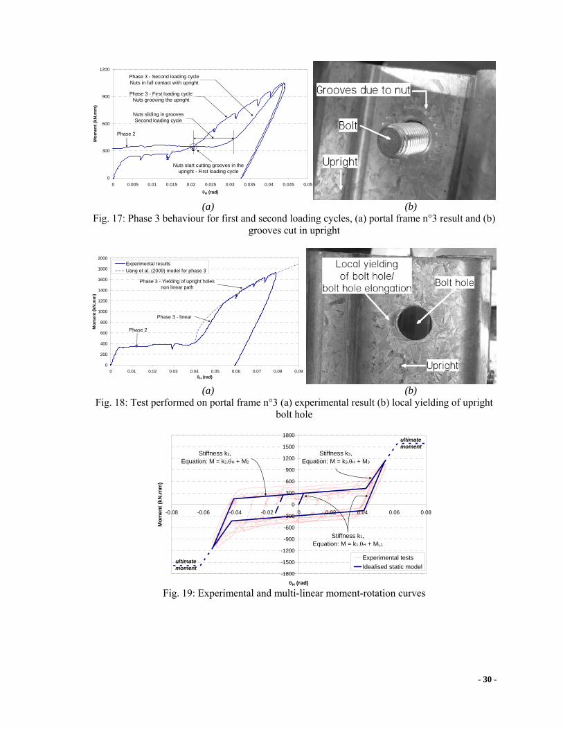
3.4.3 Portal frame n°3 experimental results
Fig. 18 (a) shows the experimental moment-rotation curves for the failure test performed
on portal frame n°3. The test was terminated before reaching the maximum moment because of
excessive rotation of the loading device, as shown in Fig. 11. As shown in Fig. 18 (a), phase 3
follows an essentially linear path until the bearing pressure produces local yielding of the bolt
holes, as illustrated in Fig. 18 (b). Using the upright and portal beam characteristics given in
Table 1 (with the ultimate tensile strength Fu of the portal beam material taken as the ultimate
tensile strength of the upright in the absence of experimental data), the moment-rotation model
for the third phase proposed by Uang et. al. [19] and summarised in Section 2.2 is also plotted in
Fig. 18 (a). Good agreement is found between the experimental results and the Uang et. al.’s [19]
model.
4 Cyclic multi-linear moment rotation curve
The moment-rotation curves shown in Figs. 12 to 14 can be idealised by multi-linear
moment-rotation curves. Average stiffness values k1, k2 and k3 for phases 1, 2 and 3 respectively
as well as average constant moments M1, M2 and M3 for multi-linear moment-rotation equations
for each phase are given in Table 4. The stiffness values given in Table 4 are averages calculated
from the moment-rotation equations of all tests obtained by performing a first-order polynomial
interpolation for each phase. The first loading cycle for phase 3 is ignored in the calculations.
Fig. 19 compares the experimental test results and the multi-linear curves given in Table 4.
For the purpose of the comparison, the experimental results are translated horizontally to be
symmetrically centred about the origin.

- 17 -
5 Design of drive-in and drive-through racks with bolted moment portal beam to
upright connections
Storage racks are slender structures, sensitive to second-order effect, and consequently the
main international racking specifications ([3-5]) require P-Δ effects to be incorporated in the
design. These specifications consider the initial looseness in tab connectors as frame
imperfections (out-of-plumb), which is generally accounted for in the design by means of
notational horizontal forces Fout-of-plumb,
WF plumbofout ⋅=−− θ (13)
where θ is the out-of-plumb angle and W is the vertical load. For braced and unbraced racks, the
AS 4084 [4] requires the connection looseness to be taken into account while the EN 15512 [5]
only requires the connection looseness to be considered for unbraced racks. When
experimentally testing the cyclic shear stiffness of upright frames in the cross-aisle direction,
Godley and Beale [28] encountered similar cyclic behaviour to that reported in this paper. They
recommended incorporating the measured looseness in the rack out-of-plumb and to design the
rack based on the stiffness k3 associated with the bolts in bearing as shown in Fig. 20. While
rational and easy to implement, this recommendation may lead to conservative results in some
cases, especially for the tested portal beam to upright connections which experience a significant
amount of looseness. By ensuring a sufficient torque in the bolts during installation, the
looseness in a bolted moment connection only develops after a significant moment is applied to
the connection, and in normal operating conditions, no bolt slippage may occur. If first yield
occurs at a lower moment in the bolted connection than the one initiating phase 2, then
considering the looseness in the connection would considerably increase the bending in the
upright due to the combined effect of the increased horizontal forces and the P-Δ effect.
As a worked example illustrating this remark, a 7.5 meter high drive-in rack, with two rail
beam elevations, four pallets deep, six bays wide is designed to carry 1200 kgs pallet load

- 18 -
following current industry practice. The design is carried out using the proprietary software RAD
([29]), developed in-house by Dematic Pty. Ltd. The spine and plan bracings run over two bays
and the rack features two upright frames in the cross-aisle direction. The maximum action-to-
capacity ratios given by RAD are equal to 0.96 for member check and to 0.88 for serviceability
check. The section properties of the upright, portal beams, rail beams and frame bracings are
shown in Table 5.
A Finite Element model of the rack is built in Abaqus [30], similarly to the Finite Element
model calibrated against experimental test results for a full-scale drive-in rack structure ([31]).
The base plate rotational stiffness is modelled as a linear rotational spring with stiffness
determined for the axial force in the uprights. Pallets are not modelled in the Finite Element
analysis. The out-of-plumb is introduced as horizontal point forces acting at the intersections
between rail beams and uprights, the magnitude of which are proportional to the vertical loads
acting at the particular beam level. Pallet loads are introduced as vertical uniformly distributed
forces on the rail beams. The rack is fully loaded.
The portal beam to upright rotational stiffness is introduced in the FE model using four
different approaches: (i) using the multi-linear curve shown in Fig. 21 and introduced in Section
4, with an arbitrary ultimate moment of 2500 kN.mm (accurate solution), (ii) using the stiffness
k3 as shown in Fig. 20, with an arbitrary ultimate moment of 2500 kN.mm and with an additional
out-of-plumb Φ1 due to the looseness in the connection, (iii) using a linear rotational stiffness k1
without an ultimate moment and an additional out-of-plumb Φ1, and (iv) using a pinned
connection without an additional out-of-plumb Φ1.
The out-of-plumb angle θ is determined following the AS 4084 [4] recommendation as,
1011
21
Φ+⎟⎠⎞
⎜⎝⎛ +Ψ=
nθ (14)
where ψ0 is the initial out-of-plumb equal to 0.007 rad for braced manually operated racks and n
is the number of bays interconnected. Φ1 is the connection looseness, equal to 0.04 rad herein as

- 19 -
in Figs. 12 to 14. To summarise, in the analyses without an additional out-of-plumb (approaches
(i), (iii) and (iv)), Φ1 is taken equal to zero and an out-of-plumb angle θ equal to 0.00408 rad is
considered. In the analysis with an additional out-of-plumb due to the connection looseness
(approach (ii)), an out-of-plumb angle θ equal to 0.04408 rad is considered.
Figs. 22 (a) and (b) plot the down-aisle displacement at the top front of the rack and the
bending moment for the critical upright respectively, for the four portal beam to upright types of
connection. It can be seen that considering the additional out-of-plumb in the connection
(approach (ii)) considerably increases the down-aisle motion of the rack and the bending moment
in the upright, leading to excessive internal forces in the upright. However, considering a linear
stiffness k1 (approach (iii)) or a released moment (approach (iv)) for the portal beam to upright
connection leads to results close to the accurate solution at the factored design load. This implies
that the base plates and the spine and plan bracings provide the major contributions in restraining
the down-aisle displacement of the rack as acknowledged in the EN 15512 [5] in which Φ1 = 0
for braced racks.
The same rack is therefore now studied in a drive-through configuration with the spine
bracing removed. In the drive-through rack configuration, RAD gives a design pallet load of 690
kg with action-to-capacity ratios equal to 0.64 for member check and 1.00 for serviceability
check. Fig. 23 plots the corresponding curves to those shown in Fig. 22 but for the drive-through
rack configuration. It can be observed, that incorporating the portal beam to upright connection
looseness in the out-of-plumb (approach (ii)) still leads to excessive displacements of the rack
and bending moment in the upright compared to the accurate approach (i). It can also be
observed that considering a linear stiffness k1 (approach (iii)) in the design leads to similar
results to the accurate solution at the design load of the rack, emphasising that slippage does not
occur in the portal beam to upright connections at the design load. However, contrary to the
drive-in rack configuration, the stability of the rack now depends solely on the rotational
stiffness of the base plate connection and the portal beam to upright connection, and releasing

- 20 -
the moment between portal beams and uprights (approach (iv)) leads to excessive displacements
and moments compared to the accurate solution.
The behaviour of the bolted moment connection between portal beams and uprights can
then be incorporated in the design of drive-in (braced) and drive-through (unbraced) racks using
two alternative approaches. First, a linear stiffness k1, associated with the initial stiffness of the
connection before slippage occurs, can be used to design the rack without an additional out-of-
plumb due to looseness in the connection. In this approach, it needs to be checked that at the
design load the moment in the portal beam to upright connection is less than the moment
initiating slippage. Second, the complete moment rotational curve can be modelled using a multi-
linear curve as shown in Fig. 21 (approach (i)), thus ensuring representative displacements and
internal forces in the rack members. Especially for drive-through racks, these design
recommendations would lead to lighter structures than if designed with an additional out-of-
plumb Φ1 and/or a pinned connection between the upright and portal beam.
6 Conclusions
This paper reviews the current practices for determining the pallet beam/portal beam
stiffness for storage racks and the characteristics of bolted moment connections between cold-
formed steel members. By combining high moment capacity and stiffness, bolted moment
connections represent an economical and feasible alternative to tab connectors for portal beam to
upright connections for drive-in and drive-through storage racks. Experimental test results show
significant looseness in the bolted connection after a high initial rotational stiffness. Current
research on bolted moment connections focus on structures not sensitive to second-order P-Δ
effects and ignore looseness in the connector. Yet, the P-Δ effect is important for storage racks
and international racking specifications require the connector looseness to be incorporated in the
design, especially for unbraced racks. Contrary to tab connectors in which the looseness is
initially present in the connection, Finite Element results on drive-in and drive-through racks

- 21 -
show that it is likely that at the design load, the moment in the bolted portal beam to upright
connection is lower that the one inducing slippage in the connection, and consequently the
looseness in the connection can be disregarded. If this is not the case, connection looseness must
be considered in the design. Finally, this paper presents methods for the design of drive-in and
drive-through racks with bolted moment portal beam to upright connections.
7 Acknowledgment
The authors would like to thank Dr Murray Clarke and Dr Lip Teh from Dematic Pty Ltd
for their valuable comments to this research program. The authors are grateful to Dematic Pty
Ltd for supplying all testing materials at no cost, and making RAD design software available for
the research program.
8 References
[1] N. Baldassino, C. Bernuzzi, Analysis and behaviour of steel storage pallet racks, Thin-
Walled Structures 37 (4) (2000) 277-304.
[2] T. Pekoz, G. Winter, Cold-formed steel rack structures, in: W.W. Yu (Ed.), 2nd Specialty Conference on Cold-Formed Steel Structures, St Louis, Missouri, USA, 1973, pp. 603-615.
[3] RMI, Specification for the design, testing and utilization of industrial steel storage racks, Rack Manufacturers Institute, Charlotte, U.S.A., 2008.
[4] AS 4084, Steel storage racking, Vol. AS 4084, Standards Australia, Sydney, Australia, 1993.
[5] EN 15512, Steel static storage systems - Adjustable pallet racking systems - Principles for structural design, Vol. EN 15512, European Committee for Standardization (CEN), Brussels, Belgium, 2009.
[6] FEM, Section X - Recommendations for the design of steel static pallet racking and shelving, Federation Europeenne de la Manutention, Brussels, Belgium, 1998.
[7] F.D. Markazi, R.G. Beale, M.H.R. Godley, Experimental analysis of semi-rigid boltless connectors, Thin-Walled Structures 28 (1) (1997) 57-87.
[8] R.E. McConnel, S.J. Kelly, Structural aspects of the progressive collapse of warehouse racking, The Structural Engineer 61A (1983) 343-347.

- 22 -
[9] C. Bernuzzi, C.A. Castiglioni, Experimental analysis on the cyclic behaviour of beam-to-column joints in steel storage pallet racks, Thin-Walled Structures 39 (2001) 841-859.
[10] E. Harris, Sway behaviour of high rise steel storage racks, University of Sydney, 2006.
[11] A.T. Sarawit, T. Pekoz, Design of industrial storage racks, in: R.A. LaBoule, W.W. Yu (Eds.), 16th International Specialty Conference on Cold-Formed Steel Structure Orlando, Florida, USA, 2002, pp. 369-384.
[12] M. Abdel-Jaber, R.G. Beale, M.H.R. Godley, Numerical study on semi-rigid racking frames under sway, Computers & Structures 83 (28-30) (2005) 2463-2475.
[13] M. Abdel-Jaber, R.G. Beale, M.H.R. Godley, A theoretical and experimental investigation of pallet rack structures under sway, Journal of Constructional Steel Research 62 (1-2) (2006) 68-80.
[14] K.F. Chung, L. Lau, Experimental investigation on bolted moment connections among cold formed steel members, Engineering Structures 21 (10) (1999) 898-911.
[15] M.F. Wong, K.F. Chung, Structural behaviour of bolted moment connections in cold-formed steel beam-column sub-frames, Journal of Constructional Steel Research 58 (2) (2002) 253-274.
[16] J.B.P. Lim, D.A. Nethercot, Ultimate strength of bolted moment-connections between cold-formed steel members, Thin-Walled Structures 41 (11) (2003) 1019-1039.
[17] J.B.P. Lim, D.A. Nethercot, Stiffness prediction for bolted moment-connections between cold-formed steel members, Journal of Constructional Steel Research 60 (1) (2004) 85-107.
[18] R. Zaharia, D. Dubina, Stiffness of joints in bolted connected cold-formed steel trusses, Journal of Constructional Steel Research 62 (3) (2006) 240-249.
[19] C. Uang, A. Sato, J. Hong, K. Wood, Cyclic testing and modeling of cold-formed steel special bolted moment frame, Submitted to Journal of Structural Engineering 0 (2009) 0-0.
[20] D. Dubina, R. Zaharia, Cold-formed steel trusses with semi-rigid joints, Thin-Walled Structures 29 (1-4) (1997) 273-287.
[21] W.K. Yu, K.F. Chung, M.F. Wong, Analysis of bolted moment connections in cold-formed steel beam-column sub-frames, Journal of Constructional Steel Research 61 (9) (2005) 1332-1352.
[22] J.B.P. Lim, D.A. Nethercot, Finite element idealization of a cold-formed steel portal frame, Journal of Structural Engineering 130 (1) (2004) 78-94.
[23] S. Kitipornchai, F.G.A. Al-Bermani, A.H. Peyrot, Effect of Bolt Slippage on Ultimate Behavior of Lattice Structures, Journal of Structural Engineering 120 (8) (1994) 2281-2287.
[24] A. Sato, C. Uang, Seismic design procedure development for cold-formed steel-special bolted moment frames, Journal of Constructional Steel Research 65 (4) (2009) 860-868.

- 23 -
[25] J.W. Fisher, Behaviour of fasteners and plates with holes, Journal of the Structural Division 91 (1965) 265-286.
[26] S.F. Crawford, G.L. Kulak, Eccentrically loaded bolted connections, Journal of the Structural Division 97 (1971) 765-783.
[27] B.P. Gilbert, K.J.R. Rasmussen, Experimental test on steel storage rack components, in: T.U.o.S. School of Civil Engineering, Australia (Ed.), School of Civil Engineering, The University of Sydney, Australia, 2009.
[28] M.H.R. Godley, R.G. Beale, Investigation of the effects of looseness of bracing components in the cross-aisle direction on the ultimate load-carrying capacity of pallet rack frames, Thin-Walled Structures 46 (7-9) (2008) 848-854.
[29] Dematic, RAD - User manual, Dematic, Pty. Ltd., Sydney, Australia, 2006.
[30] Abaqus, Abaqus ver. 6.5-4 - User manual, ABAQUS, Inc., Providence, USA, 2005.
[31] B.P. Gilbert, K.J.R. Rasmussen, Finite Element modelling of steel drive-in rack structures, in: T.U.o.S. School of Civil Engineering, Australia (Ed.), School of Civil Engineering, The University of Sydney, Australia, 2009.

- 24 -
Fig. 1: Typical selective storage rack with base plate and pallet to column connector shown
Fig. 2: Drive-in and drive-through racks

- 25 -
Fig. 3: Example of beam end connector
Fig. 4: Cantilever test set-up from the [4]
Fig. 5: Portal frame test set-up from the [4]

- 26 -
(a) (b)
Fig. 6: Portal frame test deformation (a) application of pallet load and (b) application of lateral load
Fig. 7: Typical moment-rotation characteristic of bolted connection (from [20])
Fig. 8: Pallet beam to upright bolted moment connection tested

- 27 -
(a) (b)
Fig. 9: Portal frame experimental test set-up (a) set-up and (b) photo of actual set-up
(a) (b)
Fig. 10: Portal frame deformation broken into two parts (a) portal sway and (b) connection stiffness
Fig. 11: Excessive rotation of loading device when testing to failure (Top view)

- 28 -
-800
-600
-400
-200
0
200
400
600
800
-0.04 -0.03 -0.02 -0.01 0 0.01 0.02 0.03 0.04 0.05 0.06
θH (rad)
Mom
ent (
kN.m
m)
Phase 1Phase 2
Unloading/reloading following phase 1
Phase 3
Unloading before reaching phase3 for the second cycle
Phase 3 missed
Fig. 12: Connection moment-rotation curve for portal frame 1
-1200
-900
-600
-300
0
300
600
900
1200
-0.07 -0.05 -0.03 -0.01 0.01 0.03 0.05
θH (rad)
Mom
ent (
kN.m
m)
Test 1 - 2 incomplete cyclesTest 2 - Loading to notice phase 3Test 3 - 1 complete cycle
Phase 1Phase 2
Unloading/reloadingfollowing phase 1
Phase 3
Unloading before reachingphase 3 for the second cycle
Phase 3
Phase 2
Fig. 13: Connection moment-rotation curve for portal frame 2
-1200
-900
-600
-300
0
300
600
900
1200
-0.07 -0.05 -0.03 -0.01 0.01 0.03 0.05
θH (rad)
Mom
ent (
kN.m
m)
Phase 1
Phase 2
Unloading/reloadingfollowing phase 1
Phase 3
Phase 3
Phase 2
Fig. 14: Connection moment-rotation curve for portal frame 3

- 29 -
Fig. 15: Connection rotation during phases
Fig. 16: Portal beam to upright connection deformation during phase 3
- 30 -
0
300
600
900
1200
0 0.005 0.01 0.015 0.02 0.025 0.03 0.035 0.04 0.045 0.05
θH (rad)
Mom
ent (
kN.m
m)
Phase 3 - First loading cycleNuts grooving the upright
Phase 3 - Second loading cycleNuts in full contact with upright
Nuts start cutting grooves in theupright - First loading cycle
Phase 2
Nuts sliding in groovesSecond loading cycle
(a) (b) Fig. 17: Phase 3 behaviour for first and second loading cycles, (a) portal frame n°3 result and (b)
grooves cut in upright
0
200
400
600
800
1000
1200
1400
1600
1800
2000
0 0.01 0.02 0.03 0.04 0.05 0.06 0.07 0.08 0.09θH (rad)
Mom
ent (
kN.m
m)
Experimental resultsUang et al. (2009) model for phase 3
Phase 2
Phase 3 - linear th
Phase 3 - Yielding of upright holesnon linear path
(a) (b) Fig. 18: Test performed on portal frame n°3 (a) experimental result (b) local yielding of upright
bolt hole
-1800
-1500
-1200
-900
-600
-300
0
300
600
900
1200
1500
1800
-0.08 -0.06 -0.04 -0.02 0 0.02 0.04 0.06 0.08
θH (rad)
Mom
ent (
kN.m
m)
Experimental testsIdealised static model
Stiffness k2, Equation: M = k2.θH + M2
Stiffness k3, Equation: M = k3.θH + M3
Stiffness k1, Equation: M = k1.θH + Mi,1
ultimate moment
ultimate moment
Fig. 19: Experimental and multi-linear moment-rotation curves

- 31 -
Fig. 20: Design storage racks with stiffness k3 and with connection looseness considered in the
out-of-plumb
Fig. 21: Design storage racks with multi-linear moment-rotation curve including the connection
looseness – No additional out-of-plumb
(a) (b)
Fig. 22: Drive-in rack FE results for different portal beam to upright stiffness models (a) top front displacement and (b) moment in the critical upright at floor elevation

- 32 -
(a) (b)
Fig. 23: Drive-through rack FE results for different portal beam to upright stiffness models (a) top front displacement and (b) moment in the critical upright at floor elevation
Table 1 Section properties
Member Name Gross area
(mm²)
Thick (mm)
Yield stress (MPa)
Ultimate strength (MPa)
Imajor axis (mm4)
Iminor axis (mm4)
J (mm4)
Warping (mm6)
Upright RF12519 727.9 1.9 459(1) 513(1) 1.328×10⁶ 6.852×10⁵ 780.6 2.510×10⁹
Portal beam SB15019 559.1 1.9 450(2) -- 1.746×10⁶ 1.683×10⁵ 672.8 1.011×10⁹
(1): From average coupon test values, (2): Nominal value
Table 2 Values used in Eq. 9
h (mm) h1 (mm) L (mm) EIc (kN.mm²)
kc (kN.mm) EIb (kN.mm²)
kb (kN.mm)
690 625 1475 2.899×10⁸ 4.639×10⁵ 3.608×10⁸ 2.471×10⁵ Table 3: Values used in Eq. 9
Table 4 Connection stiffness
Phase 1 Phase 2 Phase 3 k1
(kN.mm/rad) Mi,1 (kN.mm) k2
(kN.mm/rad) M2 (kN.mm) k3
(kN.mm/rad) M3 (kN.mm)
96326 (*) 3289 ± 286 59345 ± 2091 (*): Mi,1 depends of the point of change between loading and unloading
Table 5 Section properties for the FE rack
Member Gross area (mm²)
Imajor axis (mm4)
Iminor axis (mm4)
J (mm4)
Warping (mm6)
Upright 441.5 6.603×10⁵ 2.778×10⁵ 331.1 1.264×10⁹ Portal beam 559.1 1.746×10⁶ 1.683×10⁵ 672.8 1.011×10⁹ Rail beam 640.8 1.450×10⁶ 6.067×10⁵ 771.1 4.638×10⁸
Frame bracing 283.7 2.662×10⁵ 9.928×10⁴ 212.8 1.337×10⁸


![[SATO] Bolted Flange Plate Moment Connections](https://img.pdfslide.us/doc/110x75/577cd67d1a28ab9e789c841c/sato-bolted-flange-plate-moment-connections.jpg)