Embed Size (px)
Citation preview

8/13/2019 Boiler Operation and Control
http://slidepdf.com/reader/full/boiler-operation-and-control 1/99

8/13/2019 Boiler Operation and Control
http://slidepdf.com/reader/full/boiler-operation-and-control 2/99
Boiler Operation And Control Page 2
1. Operation in a glimpse:
A boiler operates using the feed water system, the steam system, the fuel
system and the draft system.
The feed water system supplies water to the boiler.
The steam system controls and directs the steam produced in the boiler.
The fuel system supplies fuel and controls combustion to produce heat.
The draft system regulates the movement of air for combustion and evacuates
gases of combustion.
Water, steam fittings and accessories are required to supply and control water
and steam in the boiler. Boiler fittings or trim are components such as valves
directly attached to the boiler. Accessories are pieces of equipment not
necessarily attached to the boiler, but required for the operation of the boiler.
2. A short description of the common boiler devices in
operation:
1. Safety Valves are the most important fittings on the
boiler. They should open to release pressure when
pressure inside the boiler exceeds the maximum
allowable working pressure or MAWP. Safety valves
are installed at the highest part of the steam side of
the boiler. No other valve shall be installed between
the boiler and the safety valve. Safety valve capacity is
measured in the amount of the steam that can be
discharged per hour.
The safety valve will remain open until sufficient steam
is released and there is a specific amount of drop in
Safet Valve
8/13/2019 Boiler Operation and Control
http://slidepdf.com/reader/full/boiler-operation-and-control 3/99
Boiler Operation And Control Page 3
pressure. This drop in pressure is the blow down of the safety valve. Safety
valve capacity and blow down is listed on the data plate on the safety valve.
Spring loaded safety valves are the most common safety valves. A spring exerts
pressure on the valve against the valve seat to keep the valve closed. When
pressure inside the boiler exceeds the set popping pressure, the pressure forces
the valve open to release. The number of safety valves required and the
frequency and procedures for testing safety valves is also specified by the ASME
Code. Adjustment or repairs to safety valves must be performed by the
manufacturer or an assembler authorized by the manufacturer.
2. Water fittings and accessories control the amount, pressure and temperature
of water supplied to and from the boiler.Water in the boiler must be maintained at the normal operating water level or
NOWL. Low water conditions can damage the boiler and could cause a boiler
explosion. High water conditions can cause carryover. Carryover occurs when
small water droplets are carried in steam lines. Carryover can result in water
hammer. Water hammer is a banging condition caused by hydraulic pressure
that can damage equipment.
3. Feed water Valves control the flow of feed water from the feed water pump to
the boiler.
Feed water stop valves are globe valves located on the feed water line. They
isolate the boiler from feed water accessories. The feed water stop valve is
positioned closest to the boiler to stop the flow of water out of the boiler for
maintenance, or if the check valve malfunctions. The feed water check valve is
located next to the feed water stop valve and prevents feed water from flowingfrom the boiler back to the feed water pump. The feed water check valve opens
and closes automatically with a swinging disc. When water is fed to the boiler it
opens. If water flows back from the boiler the valve closes.
4. Water Column minimizes the water turbulence in the gage glass to provide
accurate water level reading.

8/13/2019 Boiler Operation and Control
http://slidepdf.com/reader/full/boiler-operation-and-control 4/99
Boiler Operation And Control Page 4
Ga e Glass
Water columns are located at the NOWL, with the lowest part of the water
column positioned at least 3" above the heating system. Water columns for
high pressure boilers consist of the main column and three tricocks. High and
low water alarms or whistles may be attached to the top and bottom tricocks.
5. The Gage Glass is used to visually
monitor the water level in the boiler.
Isolation valves located at the top and
bottom permit the changing of gage
glasses.
6. A Blow down Valve at the bottom of the gage glass is used to remove sludge
and sediment. Tubular gage glasses are used for pressure up to 400 psig. All
boilers must have two methods of determining the boiler water level. The gage
glass serves as the primary method of determining boiler water level. If the
water cannot be seen in the gage glass, the tricocks are used as a secondary
method of determining boiler water level. The middle tricock is located at the
NOWL. If water comes out of the middle tricock, the gage glass is not
functioning properly. If water comes out of the top tricock, there is a high water
condition in the boiler. If water comes out of the bottom tricock, water may be
safely added to the boiler. If steam comes out of the bottom tricock, water
must not be added to the boiler. Secure the fuel immediately. Adding water
could cause a boiler explosion.
7. Makeup Water replaces boiler water lost from leaks or from the lack of
condensate returned in the boiler. Makeup water is fed manually or
automatically. Boilers can have both manual and automatic systems. If the
boiler has both, the manual always bypasses the automatic system. Boiler
operators must know how to supply makeup water quickly to the boiler in the
event of a low water condition. Manual systems feed city water with a hand
operated valve. Automatic systems feed city water with a float control valve

8/13/2019 Boiler Operation and Control
http://slidepdf.com/reader/full/boiler-operation-and-control 5/99
Boiler Operation And Control Page 5
mounted slightly below the NOWL. If the float drops from a low water level, the
valve in the city water line is open. As the water level rises, the float rises to
close the valve.
8. The Low Water Fuel Cut Off shuts off fuel to the burner in the event of a low
water condition in the boiler. The low water fuel cut off is located 2" to 6"
below the NOWL. Low water fuel cut offs are available with or without an
integral water column. Low water fuel cut offs must be tested monthly or more
often depending on plant procedures and requirements. Low water fuel cut offs
operate using an electric probe or a float sensor. The float senses a drop in
water level. Switches in the low water fuel cut off are wired to the burnercontrol to shut off fuel to the burner when the water level drops in the
chamber.
9. The Feed water Regulator maintains the NOWL in the
boiler by controlling the amount of condensate return
pumped to the boiler from the condensate return
tank. The correct water level is maintained with a
feed water regulator, but boiler water level must still
be checked periodically by the boiler operator.
10. Feed water Pumps are used with
feed water regulators to pump feed
water to the boiler. Pressure must be
sufficient to overcome boiler waterpressure to maintain the NOWL in
the boiler. For maximum safety,
plants having one steam driven feed
water pump must have a back up
feed water pump driven by
electricity. Feed water pumps may be
reciprocating, centrifugal or turbine.Feed water Pump
Feed Water Regulator

8/13/2019 Boiler Operation and Control
http://slidepdf.com/reader/full/boiler-operation-and-control 6/99
Boiler Operation And Control Page 6
11.Reciprocating feed water pumps are steam driven and use a piston to discharge
water to the feed water line. They are limited in capacity and are used on small
boilers.
12. Centrifugal feed water pumps are electric motor or steam driven. They are the
most common feed water pump. Centrifugal force moves water to the outside
edge of the rotating impeller. The casing directs water from the impeller to the
discharge piping. Discharge pressure is dependent on impeller speed.
13. Turbine feed water pumps are steam driven and operate similarly to centrifugal
feed water pumps.
14. Feed water Heaters heat water before it enters the boiler drum to remove
oxygen and other gases which may cause corrosion. Feed water heaters are
either open or closed. Open feed water heaters allow steam and water to mix
as they enter an enclosed steel chamber. They are located above the feed
water pump to produce a positive pressure on the suction side of the pump.
Closed feed water heaters have a large number of tubes inside an enclosed
steel vessel. Steam and water do not come in contact, but feed water goes
through the tubes and steam is allowed in the vessel to preheat the feed water.
They are located on the discharge side of the feed water pump.
15. Bottom Blow down Valves release water from the boiler to reduce water level,
remove sludge and sediment, reduce chemical concentrations or drain the
boiler. Two valves are commonly used, a quick opening and screw valve. During
blow down the quick opening valve is opened first, the screw valve is openednext and takes the wear and tear from blow down. Water is discharged to the
blow down tank. A blow down tank collects water to protect the sewer from
the hot boiler water. After blow down, the screw valve is closed first and the
quick opening valve is closed last.
16. Steam Fittings & Accessories remove air, control steam flow, and maintain the
required steam pressure in the boiler. Steam fittings are also used to direct
steam to various locations for heating and process.

8/13/2019 Boiler Operation and Control
http://slidepdf.com/reader/full/boiler-operation-and-control 7/99
Boiler Operation And Control Page 7
17. Steam Pressure Gauges and vacuum gages
monitor pressure inside the boiler. The range of
these gages should be 1-1/2 to 2 times the MAWP
of the boiler. For example: on a low pressure
boiler, a maximum steam pressure on the
pressure gage reads 30 psig as the MAWP is 15
psig.
18. Steam Valves commonly used include a gate valve used for the main steam
stop valve and the globe valve. The main steam stop valve cuts the boiler in
online allowing steam to flow from the boiler or takes it off line. This is anoutside stem and yoke or OS&Y valve. The position of the stem indicates
whether the valve is open or closed. The valve is opened with the stem out and
closed with the stem in. This provides quick information to the boiler operator.
19. The globe valve controls the flow of steam passing under the valve seat
through the valve. This change in direction causes a decrease in steam pressure.
A globe valve decreases steam flow and can be used to vary the amount of
steam flow. This should never be used as a main steam stop valve.
Globe Valve
Pressure Gauge

8/13/2019 Boiler Operation and Control
http://slidepdf.com/reader/full/boiler-operation-and-control 8/99
Boiler Operation And Control Page 8
20. Steam Traps remove condensate from
steam in lines from the boiler. Steam traps
work automatically and increase boiler
plant efficiency. They also prevent water
hammer by expelling air and condensate
from the steam lines without loss of
steam. Steam traps are located after the
main steam header throughout the
system. Steam traps commonly used
include the inverted bucket, the
thermostatic and the float thermostatic. In
the inverted bucket steam trap steam enters the bottom flowing into theinverted bucket. The steam holds the bucket up. As condensate fills the steam
trap the bucket loses buoyancy and sinks to open the discharge valve. The
thermostatic steam trap has a bellows filled with a fluid that boils at steam
temperature. As the fluid boils vapors expand the bellows to push the valve
closed. When the temperature drops below steam temperature, the bellows
contract to open the valve and discharge condensate. A variation of the
thermostatic steam trap is the float thermostatic steam trap. A float opens and
closes depending on the amount of condensate in the trap bowl. Condensate is
drawn out by return vacuum.
21. Steam Strainers remove scale or dirt from the steam
and are located in the piping prior to steam trap
inlet. Scale or dirt can clog discharge orifices in the
steam trap. Steam strainers must be cleaned
regularly.
Steam Trap
Steam Strainer

8/13/2019 Boiler Operation and Control
http://slidepdf.com/reader/full/boiler-operation-and-control 9/99
Boiler Operation And Control Page 9
3. SUMMARY OF DEVICES USED
The safety valve is the most important fitting on the boiler.
The gage glass is used to visually monitor the water level in the boiler.
Tricocks are used as a secondary device for determining water level in the
boiler.
Makeup water replaces water lost from leaks or lack of condensate return to
the boiler.
The low water fuel cut off shuts off fuel to the burner in the event of a low
water condition.
Steam pressure gages and vacuum gages are used to indicate the pressureinside the boiler.
8/13/2019 Boiler Operation and Control
http://slidepdf.com/reader/full/boiler-operation-and-control 10/99
Boiler Operation And Control Page 10
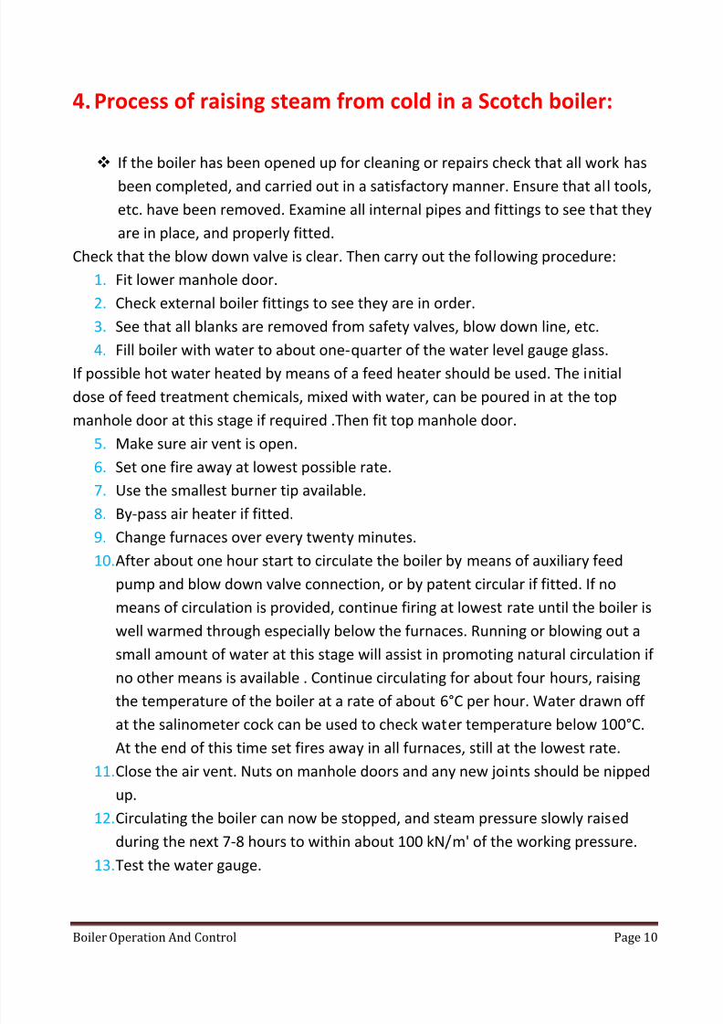
4. Process of raising steam from cold in a Scotch boiler:
If the boiler has been opened up for cleaning or repairs check that all work has
been completed, and carried out in a satisfactory manner. Ensure that all tools,
etc. have been removed. Examine all internal pipes and fittings to see that they
are in place, and properly fitted.
Check that the blow down valve is clear. Then carry out the following procedure:
1. Fit lower manhole door.
2. Check external boiler fittings to see they are in order.
3. See that all blanks are removed from safety valves, blow down line, etc.
4. Fill boiler with water to about one-quarter of the water level gauge glass.If possible hot water heated by means of a feed heater should be used. The initial
dose of feed treatment chemicals, mixed with water, can be poured in at the top
manhole door at this stage if required .Then fit top manhole door.
5. Make sure air vent is open.
6. Set one fire away at lowest possible rate.
7. Use the smallest burner tip available.
8. By-pass air heater if fitted.
9. Change furnaces over every twenty minutes.
10. After about one hour start to circulate the boiler by means of auxiliary feed
pump and blow down valve connection, or by patent circular if fitted. If no
means of circulation is provided, continue firing at lowest rate until the boiler is
well warmed through especially below the furnaces. Running or blowing out a
small amount of water at this stage will assist in promoting natural circulation if
no other means is available . Continue circulating for about four hours, raising
the temperature of the boiler at a rate of about 6°C per hour. Water drawn offat the salinometer cock can be used to check water temperature below 100°C.
At the end of this time set fires away in all furnaces, still at the lowest rate.
11. Close the air vent. Nuts on manhole doors and any new joints should be nipped
up.
12. Circulating the boiler can now be stopped, and steam pressure slowly raised
during the next 7-8 hours to within about 100 kN/m' of the working pressure.
13. Test the water gauge.

8/13/2019 Boiler Operation and Control
http://slidepdf.com/reader/full/boiler-operation-and-control 11/99
Boiler Operation And Control Page 11
The boiler is now ready to be put into service. About 12 hours should be allowed for
the complete operation provided some means of circulating the boiler is provided. If
circulation cannot be carried out, the steam raising procedure must be carried out
more slowly, taking about 18-24 hours for the complete operation.
This is due to the fact that water is a very poor conductor of heat, and heat from the
furnace will be carried up by convection currents leaving the water below the
furnace cold. This will lead to severe stresses being set up in the lower sections of
the circumferential joints of the boiler shell if steam raising is carried out too rapidly,
and can lead to leakage and 'grooving' of the end plate flanging . If steam is being
raised simultaneously on more than one boiler, use the feed pump to circulate each
boiler in turn, for about ten minutes each.
5. General Precautions to be noticed on a working boiler
There are various items to be inspected on a running boiler such as all the individual
equipment operating control signals, flow rates, temperatures and general load
conditions. They must be checked regularly so as to become aware quickly of any
deviations from the norm. Rarely do emergency conditions arise without some
previous indication, which an alert should be recognized, investigated, and then taken
corrective action before the situation gets out of hand.

8/13/2019 Boiler Operation and Control
http://slidepdf.com/reader/full/boiler-operation-and-control 12/99
Boiler Operation And Control Page 12
6. General precautions for optimum running and safety
regulations
Ensure that all boiler and associated safety shut-down devices are maintained in full
operational condition, and tested at regular intervals so as to be ready for instant
operation.
1. All alarm and automatic control systems must be kept within the manufacturer's
recommended operating limits. Do not allow equipment to be taken out of operation
for reasons which could reasonably be rectified.
2. All control room check lists must be kept up to date, with any known deviations from
normal operating procedures noted for immediate reference. Any deviations that are
un-noticed may build up to potentially serious conditions.
3.
Automatic control loops do not think for themselves, and subjected to externalirregularities will still try to perform as normal. This can result in their final control
action being incorrect, or to some other piece of equipment being overworked in an
attempt to compensate.
4. In situations where the automatic control of critical parameters is not dependable, or
where it becomes necessary to use manual control, reduce operating conditions so as
to increase acceptable margins of error.
5. High performance water tube boilers demand high quality feed water, so do not
tolerate any deterioration of feed water conditions; immediately trace the source of
any contamination, and rectify the fault.
6. Do not neglect leakage of high pressure, high temperature steam, as even minor leaks
will rapidly deteriorate.

8/13/2019 Boiler Operation and Control
http://slidepdf.com/reader/full/boiler-operation-and-control 13/99
Boiler Operation And Control Page 13
7. No attempt should be made to approach the site of leakage directly, but the
defective system should be shut down as soon as is practicable and the leakage
rectified.
8. Do not allow steam and water leaks to go un-corrected as, apart from reduction in
plant efficiency, they also lead to increased demand for extra feed with an inevitable
increase in boiler water impurities.
9. Always be alert for conditions which increase the potential fire risk within the engine
room: the best method of fire fighting is not to allow one to start. Thus all spaces,
tank tops etc. must be kept clean, dry, and well lit. This not only improves the work
environment, but also makes for the early detection of any leakage and encouragesearly repair.
10. Store any necessary stocks of combustibles remote from sources of ignition. Maintain
all oil systems tight and free from leaks and overspills. Follow correct flashing-up
procedures for the boiler at all times, especially in the case of roof-fired radiant heat
boilers. Be familiar with the fire fighting systems and equipment, and ensure that all
under your direct control are kept at a full state of readiness at all times.
11. Assess particular risk areas, especially in engine room sp aces, and formulate your
approach in case of emergency; decide in some detail how you would deal with fires
at various sites in the engine room. Make sure that your are familiar with the quick
closing fuel shut-off valves, the remotely operated steam shut-off valves etc. to
enable the boiler to be put in a safe condition if having to abandon the machinery
spaces in the event of a fire.

8/13/2019 Boiler Operation and Control
http://slidepdf.com/reader/full/boiler-operation-and-control 14/99
Boiler Operation And Control Page 14
7. The basic procedure for cleaning a boiler after a period
of service.
The frequency of boiler cleaning depends upon various factors such as the nature of
the service in which the vessel has been engaged, the quality of feed water and fuel
with which the boiler has been supplied.
1. Where possible the boiler should be shut down at least 24 hours prior to cleaning,
with if practicable the soot blowers being operated just before shut-down.
When boiler pressure has fallen to about 400 kN/m2, open blow down valves on
drums and headers to remove sludge deposits. Finally empty the boiler by running
down through suitable drains etc. Do not attempt to cool the boiler forcibly as this
can lead to thermal shock. All fuel, feed and steam lines must be isolated, and the
appropriate valves locked or lashed shut. Air vents must be left open to prevent a
vacuum forming in the boiler as it cools down.
2. Should cleaning prove to be necessary, remove any internal fittings required to
provide access to tubes etc., keeping a record of any items removed. Also note thatall attachment bolts are present and that a\l are accounted for when refitting.
3. Where the boiler design permits, cleaning can 'be carried out by mechanical brushes
with flexible drives; if these are not suitable, chemical cleaning must be used. After
cleaning, flush the boiler through with distilled water.
4. Upon completion of cleaning, tubes etc. must be proved clear. Where access is
available, search balls or flexible search wires can be used. Where neither is
practical, high pressure water or air jets can be used, the rates of discharge from the
outlet end being used to indicate whether any obstruction is present within the
tube. Where necessary, welded nipples are removed to permit sighting through
headers. With welded boilers the tubes must be carefully searched before welding
takes place and suitable precautions then taken to avoid the entry of any foreign
matter into tubes etc.

8/13/2019 Boiler Operation and Control
http://slidepdf.com/reader/full/boiler-operation-and-control 15/99
Boiler Operation And Control Page 15
5. Where work is to be carried out in the drum, rubber or plastic mats can be used,
with flexible wires attached and secured outside the drum so that they are not left
inside when the boiler is closed up.
6. Check all orifices to boiler mountings to prove that they are clear, and ensure that all
tools, cleaning materials etc. have been removed from the boiler. All internal fittings
removed must be replaced. Fit new gaskets to all doors and headers, and close up
the boiler.
7. All personnel working in the boiler must be impressed with the importance of the
avoidance of any objects entering the tubes after the boiler has been searched, but
that if a mishap should occur it must be reported before the boiler is finally closedup.
8. External Cleaning Spaces between tubes can become choked with deposits which are
not removed by soot blowing. Where sufficiently loose they may be removed by dry
cleaning using brushes or compressed air. But in most cases water washing will be
necessary. Washing will require hot water, preferably fresh, under pressure and
delivered by suitable lances. The water serves two purposes, dissolving the soluble
deposits and then breaking up and flushing away the loosened insoluble residue.
9. Once started. Washing should be continuous and thorough, as any half-dissolved
deposits remaining tend to harden off, baking on hard when the boiler is again fired,
then to prove extremely difficult to remove during any subsequent cleaning
operations.
10. Prior to cleaning, bitumastic paint should be applied around tubes where they enterrefractory material, in order to prevent water soaking in to cause external corrosion
11. . Efficient drainage must be provided, with sometimes drains below the furnace floor
requiring the removal of some furnace refractory. Where only a particular section is
to be washed, hoppers can be rigged beneath the work area, and the water drained
off through a convenient access door.

8/13/2019 Boiler Operation and Control
http://slidepdf.com/reader/full/boiler-operation-and-control 16/99
Boiler Operation And Control Page 16
12. For stubborn deposits a wetting agent may be sprayed on prior to washing.
13. After washing. Check that no damp deposits remain around tube ends, in crevices
etc. removing any remaining traces found. In a similar manner remove any deposits
in double casings around economizer headers etc., especially if they have become
damp due to water entering during the washing process.
14. Ensure that all cleaning materials, tools. Staging etc. have been removed, and any
refractory removed has been replaced, after which the access doors can be replaced.
15. Run the fans at full power with air registers full open for some minutes to clear any
loose deposits. Then dry the boiler out by flashing up in the normal manner. If thiscan’t be done immediately, then hot air from steam air heaters or from portable
units must be blown through to dry the external surfaces.

8/13/2019 Boiler Operation and Control
http://slidepdf.com/reader/full/boiler-operation-and-control 17/99
Boiler Operation And Control Page 17
8. Boiler operation from cold start
8.1.
Preoperational precautions 1. Make sure all maintenance services are finished
2. Make sure all air gates and flue gases gates are closed
3. Make sure no personal are working on site
4. Make sure all electric devices have power
5. Air compressors must be working
6. All air pressures in the system must be at normal
7. Cooling water system must be ready
8. Secondary Steam system must be on
9. Drum must be filled with water
8.2. Turning Feed Pump on:
1. Water tank level at normal (0) level
2. Lubricating oil pressure < 1.4 bar
3. Gear box at neutral position
4. Valve for controlling lowest rate of feed water must be open
5. Suction valve must be open
6. Delivery Valve and bypass must be closed.
7. Cooling water valve must be open
Steps
1. The bypass valve for the delivery pipe is opened
2. The delivery valve is opened
3. The control valve is opened for starting operation
4. The entrance valve to the economizer is opened
The operating range for rate of feed water should be about (200-250 ton/hr)
5. After the drum is filled with water the delivery valve to the drum is closed to
start operation
6. The ammonia (NH3) pump is turned on to increase the water PH
7. Hydrazine (N2H4) is used to remove Oxygen(O2) and increase PH8. Sodium Phosphate (NA3PO4) is used to remove dissolved salts

8/13/2019 Boiler Operation and Control
http://slidepdf.com/reader/full/boiler-operation-and-control 18/99
Boiler Operation And Control Page 18
8.3. Turning the air system and flue gas system on:
Precautions before operating a) Air pressure must be 8 bar
b) Cooling water system must be normal point
c) Inlet and outlet gates for the air must be closed
d) Inlet and outlet gates for the flue gases must be closed
Ai r pre heaters are to be tu rn ed on no w
a) Open the inlet and outlet gates for the flue gases
b) Open the inlet and outlet gates for the air
c)
The forced air fan is to be turned on nowd) After 15 sec the induced fan is to be turned on.
8.4. Turning the Fans on:
Precautions for turning fans on:
1. Air Preheater must be turned on
2. Cooling water system must be operational
3. Air suction gates must be closed on both sides
4. Air delivery gates must be closed on both sides
5. Lubricating oil pump must be operational
6. Hydraulic coupling must be at normal (0) level
Turning air Fans on procedure:
1. Turn the fan on
2. Hydraulic coupling is to be opened 20 %3. The delivery gate for the fan is to be opened
4. The suction gate for the fan is to be opened
The hydraulic coupling and the fan air suction gates must be set to AUTO setting
All gates must be put to AUTO setting as follows:
Over fire Damper 20 % open
Aux. Dampers 40 % open
Fuel Air Damper 60%

8/13/2019 Boiler Operation and Control
http://slidepdf.com/reader/full/boiler-operation-and-control 19/99
Boiler Operation And Control Page 19
Turning the flue gas fan and flame detector on:
1. Air fans must be turned on
2. Outlet gates for air must be open
3. Circulating Flue gases fans are to be turned on now
8.5. Operating Precautions:
1. Air fans must be on
2. Cooling water system must be operational
3. Inlet and outlet flue gases gates must be closed
4. Heater gates must be opened5. Lubricating oil pump must be on
Secondary steam system must be turned on
Secondary steam must be at 360 C at about 13.5 bar
Secondary steam destinations:
1. Air heaters
2. Gas absorbers
3. Air dumpers
4. steam atomizer burners
5. Secondary steam for steam turbines
8.6. Fuel System:
1. Fuel level must be normal
2. Leakage preventing pump must be operational
3. suction valve must be opened
4. control valve for the lowest level of fuel must be opened
5. the delivery valve must be opened
The main fuel pump can now be turned on
Minimum pressure for the fuel is 20 bar by adjusting the control valve
The steam atomizing system is now to be turned on

8/13/2019 Boiler Operation and Control
http://slidepdf.com/reader/full/boiler-operation-and-control 20/99
Boiler Operation And Control Page 20
After checking that the steam level is normal the inlet valve for the secondary steam is
to be opened
The atomizing steam pressure is to be 11 bar
8.7. Purging condition
1. Air flow not much than 30%
2. One or more FDF running
3. Fuel Oil trip valve closed
4. Fuel gas trip valve closed
5. All igniter off
6. All scanner no flame.
7. MFT
8. Igniter gas oil supply pressure must be proper
9. Fuel oil or gas supply pressure must be proper
10. All flue gases and air damper are to be opened
11. All burners valve must be closed
12. BCS power supply normal
13. All Aux. Damper modulating
8.8. Boiler Storage
As soon as possible after the end of the heating season, take these steps, where
applicable:
1. Remove all fuses from the burner circuit.
2. Remove soot and ash from the furnace, tubes, and flue surfaces.
3. Remove all fly ash from stack cleanout.
4.
Drain the broiler completely after letting the water cool.5. Flush the boiler to remove all sludge, and loose scale particles.
6. See that defective tubes, nipples, stay bolts, packings, and insulation are
repaired or replaced as required.
7. Clean and overhaul all boiler accessories such as safety valves, gauge glasses,
and firing equipment. Special attention should be given to low-water cutoffs
and feedwater regulators to ascertain that float (or electrode) chambers and
connections are free of deposits.
8. Check the condensate return system for tightness of components.

8/13/2019 Boiler Operation and Control
http://slidepdf.com/reader/full/boiler-operation-and-control 21/99
Boiler Operation And Control Page 21
9. My Boiler won't start - what to do first!
If you notice a change in boiler performance such as new noises, smells, rising stack
temperatures or continually resetting safety devices.
Although unexpected mechanical failures do occur boiler's safety or operational
devices is preventing your boiler from starting. Most safety devices have manual reset
buttons that need to be reset before boiler operation can continue. Continual
resetting of safety devices is an indication of unsafe operating conditions. Prompt
attention by your boiler technician is required.
Locate all devices that can prevent your boiler from starting.
9.1. Burner controller:
The controller is usually located in front of the burner. On a call for heat the controller
starts a sequence of events that ensure safe operation before the burner is allowed to
start. The controller continues to monitor burner operation while the boiler is
running. If for any reason the controller senses an unsafe operating condition it will
shut the burner off. Pushing the manual reset on the controller will often restart the
boiler.
9.2. High pressure or temperature switch:
This device is a safety backup to the "operator" control. It has a manual reset which
when pressed to start the boiler indicates that the "operator" control has failed.
9.3. Gas pressure switches on the fuel train:
The natural gas fuel train usually has two pressure switches. The low pressure switch
locks out the boiler when too little gas is available for operation. The high pressure
switch locks out the boiler when the regulator is allowing too high a gas pressure.
Both switches have a manual reset.

8/13/2019 Boiler Operation and Control
http://slidepdf.com/reader/full/boiler-operation-and-control 22/99
Boiler Operation And Control Page 22
9.4. Low water cutoff:
The low water cutoff may have a manual reset. When reset indicates a low watercondition existed in the boiler.
9.5. Other devices that may prevent the boiler from
starting:
9.5.1. Time clocks:
Time clocks or other energy management devices may restrict boiler operation during
weekends, evenings or other times of the day. Check their operating schedule.
9.5.2. Outdoor temperature limits:
These devices sense outdoor temperatures and prevent boiler operation above
certain outdoor temperatures, usually 65 degrees.

8/13/2019 Boiler Operation and Control
http://slidepdf.com/reader/full/boiler-operation-and-control 23/99
Boiler Operation And Control Page 23
10.DANGEROUS CONDITIONS
10.1. Low Water
A major reason for damages incurred to low pressure steam boilers is the low water
within the boiler. If the condition of low water exists it can seriously weaken the
structural members of the boiler, and result in needless inconvenience and cost. Low
pressure boilers can be protected by installing an automatic water level control
device.
Steam boilers are usually equipped with automatic water level control devices. It must
be noted, however, that most failures occur due to low water on boilers equipped
with automatic control devices. The water control device will activate water supply or
feed water pumps to introduce water at the proper level, interrupt the gas chain and
ignition process when the water reaches the lowest permissible level, or perform both
functions depending on design and interlocking systems. No matter how automatic a
water control device may be, it is unable to operate properly if sediment scale and
sludge are allowed to accumulate in the float chamber.
Accumulations of matter will obstruct and interfere with the proper operation of the
float device, if not properly maintained. To ensure for the reliability of the device,
procedures must be established in your daily preventive maintenance program to
allow "blow-down" the float chamber at Ieast once a day. Simply open the drain for 3
to 5 seconds making certain that the water drain piping is properly connected to a
discharge line in accordance with City Building Codes. This brief drainage process will
remove loose sediment deposits, and at the same time, test the operation of thewater level control device. If the water level control device does not function properly
it must be inspected, repaired and retested to guarantee proper operation.

8/13/2019 Boiler Operation and Control
http://slidepdf.com/reader/full/boiler-operation-and-control 24/99
Boiler Operation And Control Page 24
10.2. Overpressure
Safe operation of a boiler is dependent on a vital accessory, the safety valve. Failure to
test the safety valve on a regular basis or to open it manually periodically can result in
heavy accumulations of scale, deposits of sediment or sludge near the valve. These
conditions can cause the safety valve spring to solidify or the disc to seal, ultimately
rendering the safety valve inoperative. A constantly simmering safety valve is a danger
sign and must not be neglected. Your preventive maintenance program includes the
documentation and inspection of the safety valve. A daily test must be performed
when the boiler is in operation Simply raise the hand operating lever quickly to its
limit and allow it to snap closed. Any tendency of a sticking, binding or leaking of the
safety valve must be corrected immediately.
8/13/2019 Boiler Operation and Control
http://slidepdf.com/reader/full/boiler-operation-and-control 25/99
Boiler Operation And Control Page 25

8/13/2019 Boiler Operation and Control
http://slidepdf.com/reader/full/boiler-operation-and-control 26/99
Boiler Operation And Control Page 26
Section 2
Boiler control
1-Boiler control overview
The determinant that controls all the boiler's operations is called the 'master
demand'. In thermal power-plant the steam is generated by burning fuel, and the
master demand sets the burners firing at a rate that matches the steam production.
This in turn requires the forced draught fans to deliver adequate air for the
combustion of the fuel. The air input requires the products of combustion to beexpelled from the combustion chamber by the induced draught fans, whose flow rate
must be related to the steam flow. At the same time, water must be fed into the
boiler to match the production of steam.
As stated previously, a boiler is a complex, multivariable, interactive process. Each of
the above parameters affects and is affected by all of the others.
Funny example for load change
These days, the demand for electricity in a developed nation is also affected quite
dramatically by television broadcasts. During a major sporting event such as an
international football match, sudden upsurges in demand will occur at half-time and
full time, when viewers switch on their kettles. In the UK this can impose a sudden rise
in demand of as much as 2 GW, which is the equivalent to the total output of a
reasonably large power station.
The master demand in a power-station application
The response of a boiler/turbine unit in a power station is determined by the dynamic
characteristics of the two major items of plant. These differ quite significantly from
each other. The turbine, in very general terms, is capable of responding more quickly
than the boiler to changes in demand.
The response of the boiler is determined by the thermal inertia of its steam and water
circuits and by the characteristics of the fuel system. For example, a coal-burning

8/13/2019 Boiler Operation and Control
http://slidepdf.com/reader/full/boiler-operation-and-control 27/99
Boiler Operation And Control Page 27
boiler, with its complex fuel-handling plant, will be much slower to respond to
changes in demand than a gas-fired one.
Also, the turndown of the plant (the range of steam flows over which it will be
capable of operating under automatic control) will depend on the type of fuel being
burned, with gas-fired units being inherently capable of operating over a wider
dynamic range than their coal-fired equivalents.
The design of the master system is determined by the role which the plant is expected
to play, and here three options are available. The demand signal can be fed primarily
to the turbine (boiler-following control); or to the boiler (turbine-following control); or
it can be directed to both (co-ordinated unit control). Each of these results in a
different performance of the unit, in a manner that will now be analyzed.
1-1-Boiler-following operation
With boiler-following control, the power-demand signal modulates the turbine
throttle-valves to meet the load, while the boiler systems are modulated to keep the
steam pressure constant.

8/13/2019 Boiler Operation and Control
http://slidepdf.com/reader/full/boiler-operation-and-control 28/99
Boiler Operation And Control Page 28
How can we achieve this?
When valve closes, a drop in pressure happens, to regain the pressure to its
predetermined value, we should decrease flow rate to decrease pressure drop across
the valve, also when we decrease flow rate, pump head increases according to
performance of the centrifugal pump.
In such a system, the plant operates with the turbine throttle-valves partly closed. The
action of opening or closing these valves provides the desired response to demand
changes. Sudden load increases are met by opening the valves to release some of the
stored energy within the boiler.
When the demand falls, closing the valves increases the stored energy in the boiler.
In such a system the turbine is the first to respond to the changes. The boiler control
system reacts after these changes have been made, increasing or reducing the firing
to restore the steam pressure to the set value.

8/13/2019 Boiler Operation and Control
http://slidepdf.com/reader/full/boiler-operation-and-control 29/99
Boiler Operation And Control Page 29
1-2-Turbine-following operation
In the turbine-following system, the demand is fed directly to the boiler and the
turbine throttle-valves are left to maintain a constant steam pressure.
Particularly in the case of coal-fired plant, this method of operation offers slower
response, because the turbine output is adjusted only after the boiler has reacted to
the changed demand and as we know , the boiler response is much lower than turbine
response especially the coal type.
However, the turbine-following system enables the unit to be operated in a more
efficient manner and tuning for optimum performance is easier than with the boiler-
following system.
We use this for large base-load power plant (where the unit runs at a fixed load,
usually a high one, for most of the time), or with gas-fired plant where the response is
comparatively rapid (as if we make the system boiler following, the boiler may fail to
follow the fast response turbine).

8/13/2019 Boiler Operation and Control
http://slidepdf.com/reader/full/boiler-operation-and-control 30/99
Boiler Operation And Control Page 30
1-3-Co-ordinated unit control
However, its design demands considerable knowledge of the characteristics and
limitations of the major plant items.
Also, commissioning of this type of system demands great skill and care if the full
extent of the benefits is to be obtained. In particular, the rate-of change of the
demand signals, as well as the extent of their dynamic range, will need to be
constrained to prevent undesirable effects such as the stressing of pipework because
of excessively steep rates-of-change of temperature.
Performance restriction for the control system is very dependent on the rate of
heating the turbine and boiler.
Control parameters should always be adjusted as all system component ages and their
performance changes.

8/13/2019 Boiler Operation and Control
http://slidepdf.com/reader/full/boiler-operation-and-control 31/99
Boiler Operation And Control Page 31
1-4-Brief comparison between plant control modes
As stated above, the co-ordinated unit load controller, when properly designed,
commissioned and maintained, will provide the best possible response of the unit
within the constraints of the plant itself. But for practical reasons it is not universally
used.
1-4-1-Response of the boiler-following system
Consider what happens when a sudden rise in demand occurs. The first response is for
the throttle valves to be opened.
This increases the power generated by the machine, but it also results in the boilerpressure falling, and when this happens the boiler control system reacts by increasing
the firing rate. This is all right as far as it goes since, quite correctly, it increases the
boiler steaming rate to meet the increase in demand.
However, as the firing change comes into effect and the steam pressure rises, the
amount of power that is being generated also increases. But as it has already been
increased to meet the demand--and in fact may have already done so--the power
generated can overshoot the target, causing the throttle valves to start closing again,which raises the boiler pressure..., and so on.
1-4-2-Response of the turbine-following system
In the simplest version of the turbine-following system the boiler firing rate, and the
rate of air and feed-water admission etc., are all fixed (or, at least, held at a set value,
which may be adjusted from time to time by the boiler operator), and the turbine
throttle valves are modulated to keep the steam pressure constant. However, whenthe fuel, air and water flows of a boiler are held at a constant value the amount of
steam that is generated will not, in general, remain constant, mainly because of the
inevitable variations that will occur in parameters such as the calorific value of the
fuel, the temperature of the feed water etc. In the simple turbine-following system,
these variations are corrected by modulation of the turbine throttle valve to maintain
a constant steam pressure, but this results in variations in the power generated by the
turbine.
8/13/2019 Boiler Operation and Control
http://slidepdf.com/reader/full/boiler-operation-and-control 32/99
Boiler Operation And Control Page 32
Because the steam-generation rate of its boiler is not automatically adjusted to meet
an external demand, a plant operating under the control of a simple turbine-following
system will generate amounts of power that do not relate to the short-term needs of
the grid system. Such a plant is therefore incapable of operating in a frequency-
support mode, although this mode of operation may be used where it is not easy, or
desirable, to adjust the fuel input, for instance in industrial waste-incineration plants.
8/13/2019 Boiler Operation and Control
http://slidepdf.com/reader/full/boiler-operation-and-control 33/99
Boiler Operation And Control Page 33
2-Boiler components control
2-1-Combustion, burner and draught control
Naturally, in a fired boiler the control of combustion is extremely critical. In order to
maximize operational efficiency combustion must be accurate, so that the fuel is
consumed at a rate that exactly matches the demand for steam, and it must be
executed safely, so that the energy is released without risk to plant, personnel or
environment.
Control of combustion is achieved through controlling air and fuel flow to burner.
Theoretically speaking, burner should keep the ratio between fuel and air constant
along all load range to achieve stoichiometric mixing between them. Unfortunately,
when the realities of practical plant are involved, the situation once again becomes far
more complex than this simple analysis would suggest.

8/13/2019 Boiler Operation and Control
http://slidepdf.com/reader/full/boiler-operation-and-control 34/99
Boiler Operation And Control Page 34
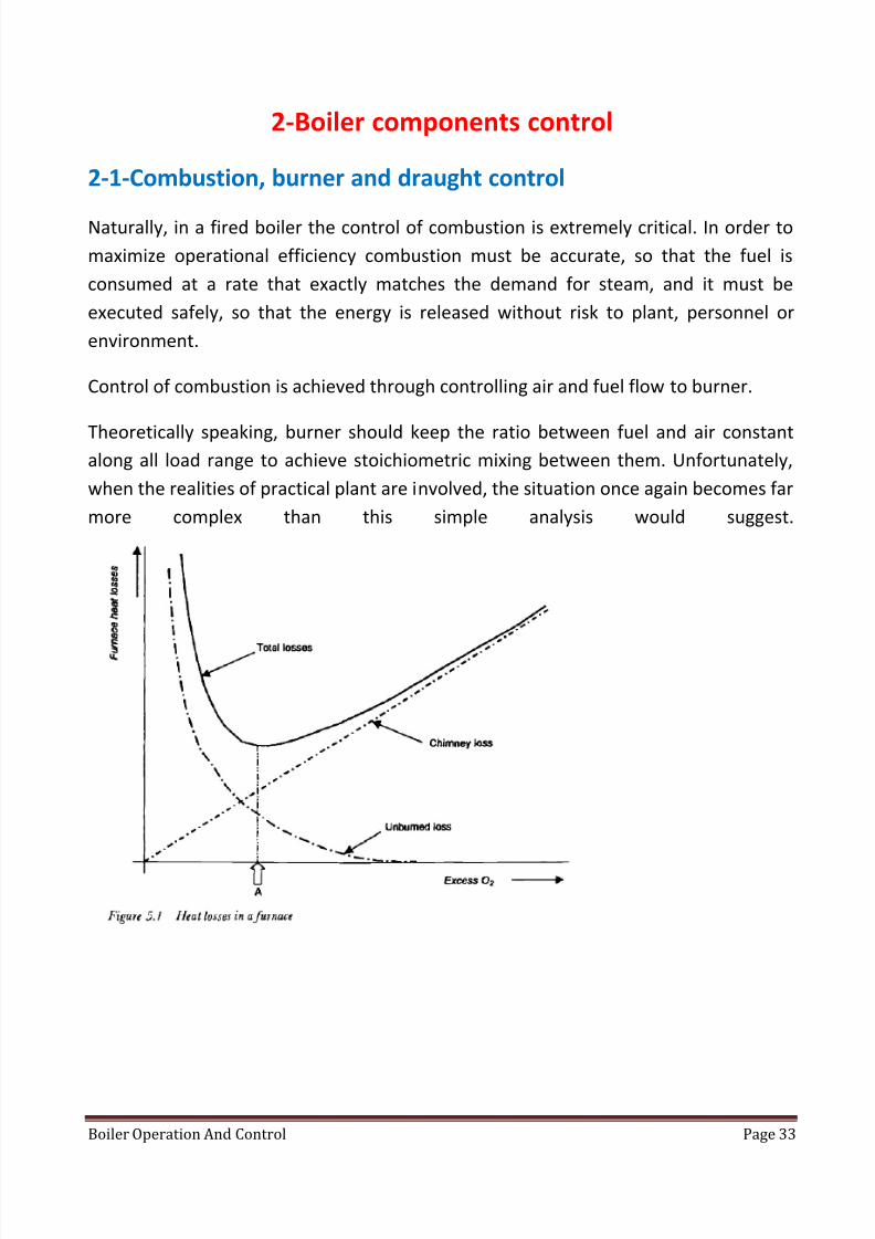
If amount of excess air is increase over a certain limit, it causes loss in efficiency.
The reduction in efficiency is due to losses which are composed of the heat wasted in
the exhaust gases and the heat which is theoretically available in the fuel, but which is
not burned. As the excess-air level increases, the heat lost in the exhaust gases
increases, while the losses in unburned fuel reduce (the shortage of oxygen at the
lower levels increasing the degree of incomplete combustion that occurs). The sum of
these two losses, plus the heat lost by radiation from hot surfaces in the boiler and its
pipe work, is identified as the total loss.
The figure above shows that operation of the plant at the point identified at 'A' will
correspond with minimum losses, and from this it may be assumed that this is the
point to which the operation of the combustion-control system should be targeted.
However, in practice air is not evenly distributed within the furnace. For example,
operational considerations require that a supply of cooling air is provided for idle
burners and flame monitors, to prevent them being damaged by heat from nearby
active burners and by general radiation from the furnace. Air also enters the
combustion chamber through leaks, observation ports, soot-blower entry points and
so on. The sum of all this is referred to as 'tramp air' or 'setting leakage'. If this is
included in the total being supplied to the furnace, and if that total is apportioned to
the total amount of fuel being fired, the implication is that some burners (at least) will
be deprived of the air they need for the combustion of their fuel.
In other words, the correct amount of air is being provided in total, but it is going to
places where it is not available for the combustion process.
Operation of the firing system must take these factors into account, and from then on
the system can apportion the fuel and air flows. If these are maintained in a fixedrelationship with each other over the full range of flows, the amount of excess air will
be fixed over the entire range.

8/13/2019 Boiler Operation and Control
http://slidepdf.com/reader/full/boiler-operation-and-control 35/99
Boiler Operation And Control Page 35
2-1-1-Burners control systems
2-1-1-1-A simple system: "parallel control"
The easiest way of maintaining a relationship between fuel flow and air flow is to usea single actuator to position a fuel-control valve and an air control damper in parallel
with each other as shown in figure below.
Here, the opening of an air-control damper is mechanically linked to the opening of a
fuel control valve to maintain a defined relationship between fuel flow and air flow.
This system is employed in very small boilers, and we can achieve a non-linear
relationship between valve opening and damper opening to be determined by the
shape of a cam, with a range of cams offering a variety of relationships.
Although this simple system may be quite adequate for very small boilers burning
fuels such as oil or natural gas, its deficiencies become increasingly apparent as thesize of the plant increases.
System problems
1-It assumes that for a given opening of fuel valve or air damper we get a certain
amount of flow and this is not true as flow depends also on pressure difference
between valves sides, also flow will depends on properties of fuel and air like density.

8/13/2019 Boiler Operation and Control
http://slidepdf.com/reader/full/boiler-operation-and-control 36/99
Boiler Operation And Control Page 36
2- Another problem is that the response times of the fuel and air systems are never
identical. Therefore, if a sudden load-change occurs and the two controlling devices
are moved to predetermined openings, the flows through them will react at different
rates.
With an oil-fired boiler, a sudden increase in demand will cause the fuel flow to
increase quickly, but the air system will be slower to react. As a result, if the fuel/air
ratio was correct before the change occurred, the firing conditions after the change
will tend to become fuel-rich until the air system has had time to catch up. This causes
characteristic puffs of black smoke to be emitted as unburned fuel is ejected to the
chimney.
On a load decrease the reverse happens, and the mixture in the combustion chamber
becomes air-rich. The resulting high oxygen content could lead to corrosion damage
to the metalwork of the boiler, and to unacceptable flue-gas emissions.
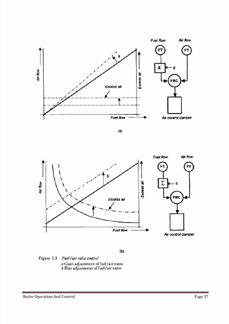
2-1-1-2-Flow ratio control
The first approach to overcoming the limitations of a simple 'parallel' system is to
measure the flow of the fuel and the air, and to use closed-loop controllers to keep
them in track with each other, as shown by the two configurations of figure shownnext page.
In each of these systems the master demand (not shown) is used to set the quantity
of one parameter being admitted to the furnace, while a controller maintains an
adjustable relationship between the two flows (fuel and air).
In the system shown in Figure a a gain block or amplifier in one of the flow-signal lines
is used to adjust the ratio between the two flows. As the gain (g) of this block is
changed, it alters the slope of the fuel-flow/airflow characteristic, changing the
amount of excess air that is present at each flow. Note that when the gain is fixed, the
amount of excess air is the same for all flows, as shown by the horizontal line.
In practice, this situation would be impossible to achieve, since some air inevitably
leaks into the furnace, with the result that the amount of excess air is proportionally
greater at low flows than high flows.
8/13/2019 Boiler Operation and Control
http://slidepdf.com/reader/full/boiler-operation-and-control 37/99
Boiler Operation And Control Page 37

8/13/2019 Boiler Operation and Control
http://slidepdf.com/reader/full/boiler-operation-and-control 38/99
Boiler Operation And Control Page 38
The system shown in figure in previous page shows a different control arrangement
working with the same idealized plant (i.e. one with no air leaking into the
combustion chamber). Here, instead of a gain function, a bias is added to one of the
signals. The effect of this is that a fixed surfeit of air is always present and this is
proportionally larger at the smaller flows, with the result that the amount of excess
air is largest at small flows, as shown. Changing the bias signal (b) moves the curve
bodily as shown.
Each of these control configurations has been used in practical plant, although the
version with bias (Figure 5.3b) exacerbates the effects of tramp air and therefore
tends to be confined to smaller boilers. The arrangement shown in figure (a) therefore
forms the basis of most practical fuel/air ratio control systems.
In these illustrations it has been assumed that the master demand is fed to the fuel
valve, leaving the air-flow controller to maintain the fuel/air ratio at the correct
desired value. When this is done, the configuration is known as a 'fuel lead' system
since, when the load demand changes, the fuel flow is adjusted first and the controller
then adjusts the air flow to match the fuel flow, after the latter has changed.
It doesn't have to be done this way. Instead, the master demand can be relayed to the
air-flow controller, which means that the task of maintaining the fuel/air ratio is then
assigned to the fuel controller. For obvious reasons this is known as an 'air-lead'
system.
So, Fuel lead system is the system which manipulates fuel flow according to load and
let the controller adjust the amount of air flow to achieve the predetermined air to
fuel ratio.
So, air lead system is the system which manipulates air flow according to load and letthe controller adjust the amount of fuel flow to achieve the predetermined air to fuel
ratio.
8/13/2019 Boiler Operation and Control
http://slidepdf.com/reader/full/boiler-operation-and-control 39/99
Boiler Operation And Control Page 39
Comparing the "fuel-lead' and 'air-lead' approaches
Of the two alternatives described above, the fuel-lead version will provide better
response to load changes, since its action does not depend on the slower-responding
plant that supplies combustion air to the furnace.
However, because of this, the system suffers from a tendency to produce fuel-rich
conditions on load increases and fuel-lean conditions on decreases in the load.
Disadvantages of working in rich fuel region
Operating in the fuel-rich region raises the risk of unburned fuel being ignited in an
uncontrolled manner, possibly causing a furnace explosion.
Disadvantages of working with too much excess air
Whereas operating with too much excess air, while not raising the risk of an
uncontrolled fire or an explosion, does cause a variety of other problems, including
back-end corrosion of the boiler structure, and undesirable stack emissions.
The air-lead system is slow to respond because it requires the draught plant to react
before the fuel is increased. Although this avoids the risk of creating fuel-richconditions as the load increases, it remains prone to such a risk as the load decreases
“as the air takes time to be reduced, hence the fuel will be injected during this period
which will make a fuel rich mixture”. However, the hazard is less than for the fuel lead
system.
Disadvantages of both systems
A further limitation of these systems (in either the fuel-lead or air-lead version) is that
they offer no protection against equipment failures, since these cannot be detected
and corrected without special precautions being taken.
For example, in the fuel-lead version, if the fuel-flow transmitter fails in such a way
that it signals a lower flow than the amount that is actually being delivered to the
furnace, the fuel/air ratio controller will attempt to reduce the supply of combustion
air to match the erroneous measurement. This will cause the combustion conditions
to become fuel rich, with the attendant risk of an explosion. Conversely, if the fuel-
flow transmitter in the air-lead system fails low, the fuel controller will attempt to

8/13/2019 Boiler Operation and Control
http://slidepdf.com/reader/full/boiler-operation-and-control 40/99
Boiler Operation And Control Page 40
compensate for the apparent loss of fuel by injecting more fuel into the furnace, with
similar risks.
2-1-1-3-Cross-limited control
Figure above shows the principles of the cross-limited combustion control system.
Individual flow-ratio controllers (FRC) (7, 8) are provided for the fuel and air systems,
respectively. The effect of the fuel/air ratio adjustment block (4) is to modify the air-
flow signal in accordance with the required fuel/air relationship. (FT) is a flow
transmitter to give a value for actual flow for fuel and air (2 & 3).
Because fuel flow and air flow are each measured as part of a closed loop, the system
compensates for any changes in either of these flows that may be caused by external

8/13/2019 Boiler Operation and Control
http://slidepdf.com/reader/full/boiler-operation-and-control 41/99
Boiler Operation And Control Page 41
factors. For this reason it is sometimes referred to as a 'fully metered' system. The
effect of the fuel/air ratio adjustment block (4) is to modify the air-flow signal in
accordance with the required fuel/air relationship.
How this system works?
So far, the configuration performs similarly to the basic systems in previous section.
The difference becomes apparent when the maximum and minimum selectors are
brought into the picture (components 5 & 6). Remembering the problems of the
differing response-rates of the fuel and air supply systems, consider what happens
when the master demand signal suddenly requests an increase in firing. Assume that,
prior to that instant; the fuel and air controllers have been keeping their respective
controlled variable in step with the demand, so that the fuel-flow and modified air-
flow signals are each equal to the demand signal.
When the master demand signal suddenly increases, it now becomes larger than the
fuel-flow signal and it is therefore ignored by the minimum-selector block (5) which
instead latches onto the modified air-flow signal (from item 4). The fuel controller
now assumes the role of fuel/air ratio controller, maintaining the boiler's fuel input
at a value that is consistent with the air being delivered to the furnace.
The air flow is meanwhile being increased to meet the new demand, since the
maximum-selector block (6) has latched onto the rising master signal.
On a decrease in load, the system operates in the reverse manner. The minimum-
selector block locks onto the collapsing master and quickly reduces the fuel flow,
while the maximum-selector block chooses the fuel flow signal as the demand for the
air-flow controller (8), which therefore starts to operate as the fuel/air ratio
controller, keeping the air flow in step with the fuel flow.
Analysis of the system will show that it is much better able to deal with plant or
control and instrumentation equipment failures. For example, if the fuel valve fails
open, the air controller will maintain adequate combustion air to meet the quantity of
fuel being supplied to the combustion chamber. This may result in over firing but it
cannot cause fuel-rich conditions to be created in the furnace. Similarly, if the fuel-
flow transmitter fails low, although the fuel controller will still attempt to
8/13/2019 Boiler Operation and Control
http://slidepdf.com/reader/full/boiler-operation-and-control 42/99
Boiler Operation And Control Page 42
compensate for the apparent loss of fuel, the air flow controller will ensure that
adequate combustion air is supplied.
2-1-1-4-Multiple-burner systems
The systems that have been described so far are based on the adjustment of the total
quantity of fuel and air that is admitted to the combustion chamber. This approach
may be sufficient with smaller boilers, where adjustment of a single fuel valve and air
damper is reasonable, but larger units will have a multiplicity of burners, fuel systems,
fans, dampers and combustion-air supplies. In such cases proper consideration has to
be given to the distribution of air and fuel to each burner or, if this is not practical, to
small groups of burners.
The concept of individually controlling air registers to provide the correct fuel/air ratio
to each burner of a multi burner boiler has been implemented, but in most practical
situations the expense of the instrumentation cannot be justified. Oil and gas burners
can be operated by maintaining a defined relationship between the fuel pressure and
the differential pressure across the burner air register (rather than proper flow
measurements), but even with such economies the capital costs are high and the
payback low. The need to provide a modulating actuator for each air register adds
further cost.
A more practical option is to control the ratio of fuel and air that flows to groups of
burners. Figure shown next page shows how the principles of a simple cross limited
system are applied to a multi burner oil-fired boiler.
The plant in this case comprises several rows of burners, and the flow of fuel oil to
each row is controlled by means of a single valve. The combustion air is supplied
through a common wind box, and the flow to the firing burners is controlled by asingle set of secondary-air dampers.

8/13/2019 Boiler Operation and Control
http://slidepdf.com/reader/full/boiler-operation-and-control 43/99
Boiler Operation And Control Page 43
In most respects the arrangement closely resembles the basic cross limited system
explained in previous section, with the oil flow inferred from the oil pressure at the
row. A function generator is used to convert the pressure signal to a flow-per-burner
signal, which is then multiplied by a signal representing the number of burners firing
in that row, to yield a signal representing the total amount of oil flowing to the
burners in the group.
Working with multiple fuels
The control systems of boilers burning several different types of fuel have to
recognize the heat-input contribution being made at any time by each of the fuels,

8/13/2019 Boiler Operation and Control
http://slidepdf.com/reader/full/boiler-operation-and-control 44/99
Boiler Operation And Control Page 44
and the arrangements become more complicated for every additional fuel that is to
be considered.
Figure above shows a system for a boiler burning oil and gas. The similarities to the
simple cross-limited system are very apparent, as are the commonalities with the fuel-
control part of the multi burner system (shown within the chain-dotted area of Figure
5.9).

8/13/2019 Boiler Operation and Control
http://slidepdf.com/reader/full/boiler-operation-and-control 45/99
Boiler Operation And Control Page 45
The cross-limiting function is performed at the minimum-selector block (5) which
continuously compares the master demand with the quantity of combustion air
flowing to the common wind box of the burner group. The gain block (6) translates
the air flow into a signal representing the amount of fuel whose combustion can be
supported by the available secondary air.
The selected signal (the load demand or the available air) ultimately forms the desired
value of both the gas and oil closed-loop controllers. But, before it reaches the
relevant controller a value is subtracted from it, which represents the heat
contributed by the other fuel (converted to the same heat/m s value as the fuel being
controlled). The conversion of oil flow to equivalent gas flow is performed in a
function generator (10), while the other conversion is performed in another such
block (14). Each of the two summator units (11 and 13) algebraically subtracts the
'other-fuel’ signal from the demand.
Note that, in the case of this system, the gas pressure signal is compensated against
temperature variations, since the pressure/flow relationship of the gas is
temperature-dependent.
As before, each fuel-flow signal represents the flow per burner and so it has to be
multiplied by the number of burners in service in order to represent the total fuel
flow.
These diagrams are highly simplified, and in practice it is necessary to incorporate
various features such as interlocks to prevent over firing and to isolate one or other of
the pressure signals when no burner is firing that fuel. (This is because a pressure
signal will exist even when no firing is taking place.)

8/13/2019 Boiler Operation and Control
http://slidepdf.com/reader/full/boiler-operation-and-control 46/99
Boiler Operation And Control Page 46
2-1-2-Draught control
We will understand draught control via inspecting draught system components, layout
and operation.
In the following section we shall see how air is delivered to the furnace at the right
conditions of flow and temperature, starting with the auxiliary plant that warms the
air and moving on to the types of fan employed in the draught plant.
The air heater
In a simple-cycle plant, air is delivered to the boiler by one or more forced draught
fans and the products of combustion are extracted from it by induced draught fans as
shown in figure below.
Figure above shows this plant in a simplified form, and illustrates how the heat
remaining in the exhaust gases leaving the furnace is used to warm the air being fed
to the combustion chamber. This function is achieved in an air heater, which can be

8/13/2019 Boiler Operation and Control
http://slidepdf.com/reader/full/boiler-operation-and-control 47/99
Boiler Operation And Control Page 47
either regenerative, where an intermediate medium is used to transfer the heat from
the exhaust gases to the incoming air, or recuperative, where a direct heat transfer is
used across a dividing partition.
In the regenerative type, air and exhaust may mix at a certain limit; this is referred to
as ‘air leakage’.
Leakage happens across the circumferential, radial and axial seals, as well as at the
hub. These leakages are minimized when the plant is first constructed, but become
greater as wear occurs during prolonged usage. When the sheer physical size of the
air heater is considered it will be appreciated that these leakages can become
significant.
2-1-2-1-Types of fan according to function
Here, classification is according to function, there are 3 types;
Forced draught fan
Induced draught fan
Booster fan

8/13/2019 Boiler Operation and Control
http://slidepdf.com/reader/full/boiler-operation-and-control 48/99
Boiler Operation And Control Page 48
In addition to the FD and ID fans mentioned above, another application for large fans
in a power-station boiler is where it is necessary to overcome the resistance
presented by plant in the path of the flue gases to the stack.
In some cases, environmental legislation has enforced the fitting of flue gas
desulphurisation equipment to an existing boiler. This involves the use of absorbers
and/or bag filters, plus the attendant ducting, all of which present additional
resistance to the flow of gases. In this case this resistance was not anticipated when
the plant was originally designed, so it is necessary to fit additional fans to overcome
the draught losses. These are called 'booster fans'.
2-1-2-2-Types of fans according to working principle
In power plant, we use 2 types of fans “according to fan design and working
principles”
Centrifugal fans
Axial flow fans
2-1-2-2-1-Centrifugal fans
The blades are set radially on the drive shaft with the air or flue gas directed to the
centre and driven outwards by centrifugal force.
2-1-2-2-2-Axial-flow fans
The air or gas is drawn along the line of the shaft by the screw action of the blades.
Whereas the blades of a centrifugal fan are fixed rigidly to the shaft, the pitch of axial-
flow fan blades can be adjusted. This provides an efficient means of controlling the
fan's throughput, but requires careful design of the associated control system becauseof a phenomenon known as 'stall', which will now be described.
2-1-2-3-Fan control constrains
There is some constrains for fan operation, this constrains are related to fan theory of
operation and its design, these limitation is explained below
8/13/2019 Boiler Operation and Control
http://slidepdf.com/reader/full/boiler-operation-and-control 49/99
Boiler Operation And Control Page 49
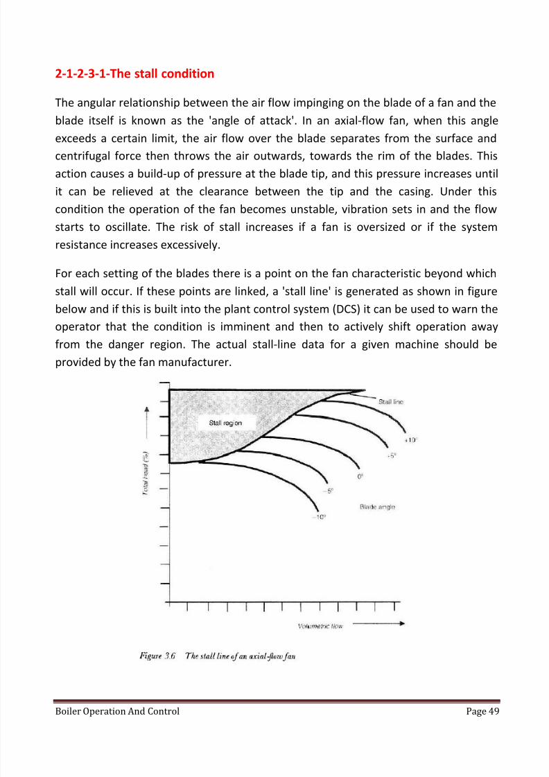
2-1-2-3-1-The stall condition
The angular relationship between the air flow impinging on the blade of a fan and the
blade itself is known as the 'angle of attack'. In an axial-flow fan, when this angle
exceeds a certain limit, the air flow over the blade separates from the surface and
centrifugal force then throws the air outwards, towards the rim of the blades. This
action causes a build-up of pressure at the blade tip, and this pressure increases until
it can be relieved at the clearance between the tip and the casing. Under this
condition the operation of the fan becomes unstable, vibration sets in and the flow
starts to oscillate. The risk of stall increases if a fan is oversized or if the system
resistance increases excessively.
For each setting of the blades there is a point on the fan characteristic beyond which
stall will occur. If these points are linked, a 'stall line' is generated as shown in figure
below and if this is built into the plant control system (DCS) it can be used to warn the
operator that the condition is imminent and then to actively shift operation away
from the danger region. The actual stall-line data for a given machine should be
provided by the fan manufacturer.

8/13/2019 Boiler Operation and Control
http://slidepdf.com/reader/full/boiler-operation-and-control 50/99
Boiler Operation And Control Page 50
2-1-2-3-2-Centrifugal fan surge
The stall condition affects only axial-flow fans. However, centrifugal fans are subjectto another form of instability. If they are operated near the peak of their
pressure/flow curve a small movement either way can cause the pressure to increase
or decrease unpredictably. The point at which this phenomenon occurs is known as
the 'surge limit' and it is the minimum flow at which the fan operation is stable.
2-1-2-4-Air flow control methods
After knowing about fans and their limitation, we will discuss methods of fan control
and characteristics of each control method.
There are 3 methods of fan control;
Damper
Fan speed
Blade angle

8/13/2019 Boiler Operation and Control
http://slidepdf.com/reader/full/boiler-operation-and-control 51/99
Boiler Operation And Control Page 51
1-Fan damper
The simplest form of damper consists of a hinged plate that is pivoted at the centre
so that it can be opened or closed across the duct. This provides a form of draught
control but it is not very linear and it is most effective only near the closed position.
Once such a damper is more than about 40- 60% open it can provide very little
additional control. Another form of damper comprises a set of linked blades across
the duct (like a Venetian blind). Such multi bladed dampers are naturally more
expensive and more complex to maintain than single-bladed versions, but they offer
better linearity of control over a wider range of operation.

8/13/2019 Boiler Operation and Control
http://slidepdf.com/reader/full/boiler-operation-and-control 52/99
Boiler Operation And Control Page 52
2-1-2-4-2-Vane control
The second form of control is by the adjustment of vanes at the fan inlet.
Such vanes are operated via a complex linkage which rotates all the vanes through the
same angle in response to the command signal from the DCS.
2-1-2-4-3-Variable-speed drives
Finally, control of fan throughput can be achieved by the use of variable speed motors
(or drives). These may involve the use of electronic controllers which alter the speed
of the driving motor in response to demand signals from the DCS or they can be
hydraulic couplings or variable-speed gearboxes, either of which allows a fixed-speed
motor to drive the fan at the desired speed. Variable speed drives offer significant
advantages in that they allow the fan to operate at the optimum speed for the
required throughput of air or gas, whereas dampers or vanes control the flow by
restricting it, which means that the fan is attempting to deliver more flow than is
required.

8/13/2019 Boiler Operation and Control
http://slidepdf.com/reader/full/boiler-operation-and-control 53/99
Boiler Operation And Control Page 53
As we know, in a fired boiler, the air required for combustion is provided by one or
more fans and the exhaust gases are drawn out of the combustion chamber by an
additional fan or set of fans. On boilers with retro-fitted flue-gas desulphurisation
plant, additional booster fans may also be provided. The control of all these fans must
ensure that an adequate supply of air is available for the combustion of the fuel and
that the combustion chamber operates at the pressure determined by the boiler
designer.
All of the fans also have to contribute to the provision of another important function -
purging of the furnace in all conditions-when a collection of unburned fuel or
combustible gases could otherwise be accidentally ignited. Such operations are
required prior to light-off of the first burner when the boiler is being started, or after a
trip.
The control systems for the fans have to be designed to meet the requirements of
start-up, normal operation and shut-down, and to do so in the most efficient mannerpossible, because the fans may be physically large and require a large amount of
power for their operation (several MW in some cases). In addition, as we know, the
performance constraints of the fans, such as surge and stall, have to be recognized, if
necessary by the provision of special control functions or interlocks.

8/13/2019 Boiler Operation and Control
http://slidepdf.com/reader/full/boiler-operation-and-control 54/99
Boiler Operation And Control Page 54
2-1-2-5-Draught system duties
The main duty of draught system is to maintain the furnace draught.
Apart from supplying air to support combustion, the FD fans have to operate inconcert with the ID fans to maintain the furnace pressure at a certain value. The
heavy solid line of figure shown below shows the pressure profile through the various
sections of a typical balanced-draught boiler system.
It shows the pressure from the point where air is drawn in, to the point where the flue
gases are exhausted to the chimney, and demonstrates how the combustion chamber
operates at a slightly negative pressure, which is maintained by keeping the FD and ID
fans in balance with each other.
If that balance is disturbed the results can be extremely serious. Such an imbalance
can be brought about by the accidental closure of a damper or by the sudden loss of
all flames. It can also be caused by mal operation of the FD and ID fans. The dashed
line on the diagram shows the pressure profile under such a condition, which known
as an 'implosion'.

8/13/2019 Boiler Operation and Control
http://slidepdf.com/reader/full/boiler-operation-and-control 55/99
Boiler Operation And Control Page 55
The results of an implosion are extremely serious because, even though the pressures
involved may be small, the surfaces over which they are applied are very large and the
forces exerted become enormous. Such an event would almost certainly result in
major structural damage to the plant.

8/13/2019 Boiler Operation and Control
http://slidepdf.com/reader/full/boiler-operation-and-control 56/99
Boiler Operation And Control Page 56
2-2-Feed water control system
Control of feed water is executed via feed water regulator, types of feed water
regulators are presented in the following sections
2-2-1-Feedwater Regulators
A boiler feedwater regulator automatically controls the water supply so that the level
in the boiler drum is maintained within desired limits.
This automatic regulator adds to the safety and economy of operation and minimizes
the danger of low or high water. Uniform feeding of water prevents the boiler from
being subjected to the expansion strains that would result from temperature changesproduced by irregular water feed. The danger in the use of a feedwater regulator lies
in the fact that the operator may be entirely dependent on it. It is well to remember
that the regulator, like any other mechanism, can fail; continued attention is
necessary.
2-2-1-1-Oldest feed water regulator
It consists of a simple float attached to lever to control feed water flow and to keep
level constant as shown above.
Next generation employs the float in a different manner as shown in figure a.

8/13/2019 Boiler Operation and Control
http://slidepdf.com/reader/full/boiler-operation-and-control 57/99
Boiler Operation And Control Page 57
For high-capacity boilers and those operating at high pressure, a pneumatic or
electrically operated feedwater control system is used.
There are basically three types of feedwater-control systems:
(1) Single element, (2) two element, and (3) three element.
2-2-1-2-Single-element control
This uses a single control loop that provides regulation of feedwater flow in response
to changes in the drum water level from its set point. The measured drum level is
compared to its set point, and any error produces a signal that moves the feedwater
control valve in proper response.

8/13/2019 Boiler Operation and Control
http://slidepdf.com/reader/full/boiler-operation-and-control 58/99
Boiler Operation And Control Page 58
Single-element control will maintain a constant drum level for slow changes in load,
steam pressure, or feedwater pressure. However, because the control signal satisfies
the requirements of drum level only, wider drum-level variation results.
2-2-1-3-Two-element control
This uses a control loop that provides regulation of feedwater flow in response to
changes in steam flow, with a second control loop correcting the feedwater flow to
ensure the correct drum water level.
The steam flow control signal anticipates load changes and begins control action in
the proper direction before the drum-level control loop acts in response to the drum
water level. The drum-level measurement corrects for any imbalance between the
drum water level and its set point and provides the necessary adjustment to cope
with the “swell and shrink” characteristics of the boiler.

8/13/2019 Boiler Operation and Control
http://slidepdf.com/reader/full/boiler-operation-and-control 59/99
Boiler Operation And Control Page 59
2-2-1-4-Three-element control
This uses a predetermined ratio of feedwater flow input to steam flow output to
provide regulation of feedwater flow in direct response to boiler load. The three-
element control regulates the ratio of feedwater flow input to steam flow output by
establishing the set point for the drum-level controller. Any change in the ratio is used
to modify the drum-level set point in the level controller, which regulates feedwaterflow in direct response to boiler load. This is the most widely used feedwater-control
system.

8/13/2019 Boiler Operation and Control
http://slidepdf.com/reader/full/boiler-operation-and-control 60/99
Boiler Operation And Control Page 60

8/13/2019 Boiler Operation and Control
http://slidepdf.com/reader/full/boiler-operation-and-control 61/99
Boiler Operation And Control Page 61
2-2-2-Types of feed water regulators
2-2-2-1-Thermohydraulic type
A thermohydraulic, or generator-diaphragm, type of boiler feedwater regulator isshown in Figure b. Connected to the radiator is a small tube running to a diaphragm
chamber. The diaphragm in turn operates a balanced valve in the feedwater line. The
inner tube is connected directly to the water column and contains steam and water.
The outside compartment, connecting the tube and valve diaphragm, is filled with
water. This water does not circulate. Heat is radiated from it by means of fins
attached to the radiator. Water in the inner tube of the regulator remains at the same
level as that in the boiler. When the water in the boiler is lowered, more of the
regulator tube is filled with steam and less with water. Since heat is transferred faster
from steam to water than from water to water, extra heat is added to the confined
water in the outer compartment. The radiating-fin surface is not sufficient to remove
the heat as rapidly as it is generated, so the temperature and pressure of the confined
water are raised. This pressure is transmitted to the balanced-valve diaphragm to
open the valve, admitting water to the boiler. When the water level in the boiler is
high, this operation is reversed.

8/13/2019 Boiler Operation and Control
http://slidepdf.com/reader/full/boiler-operation-and-control 62/99
Boiler Operation And Control Page 62
2-2-2-2-Thermostatic expansion-tube-type
The thermostatic expansion-tube-type feedwater regulator is shown in Figure c.
Because of expansion and contraction, the length of the thermostatic tube changes
and positions the regulating valve with each change in the proportioned amount of
steam and water.
A two element steam-flow-type feedwater regulator shown in the above figure
combines a thermostatic expansion tube operated from the change in water level in
the drum as one element with the differential pressure across the superheater as the
second element. The two combined operate the regulating valve.
An air-operated three-element feedwater control (Fig. 6.12a) combines three
elements to control the water level. Water flow is proportioned to steam flow, with
drum level as the compensating element; the control is set to be insensitive to the
level. In operation, a change in position of the metering element positions a pilot
valve to vary the air loading pressure to a standatrol (self-standardizing relay). The
resulting position assumed by the standatrol provides pressure to operate a pilot
valve attached to the feedwater regulator. The impulse from the standatrol passes
through a hand-automatic selector valve, permitting either manual or automatic
operation. The hand-wheel jack permits manual adjustment of the feedwater valve if
remote control is undesirable.

8/13/2019 Boiler Operation and Control
http://slidepdf.com/reader/full/boiler-operation-and-control 63/99
Boiler Operation And Control Page 63
8/13/2019 Boiler Operation and Control
http://slidepdf.com/reader/full/boiler-operation-and-control 64/99
Boiler Operation And Control Page 64
2-3-Steam temperature control
Why steam temperature control is needed:
The rate at which heat is transferred to the fluid in the tube banks of a boiler orHRSG will depend on the rate of heat input from the fuel or exhaust from the gas
turbine. This heat will be used to convert water to steam and then to increase the
temperature of the steam in the superheat stages. In a boiler, the temperature of the
steam will also be affected by the pattern in which the burners are fired, since some
banks of tubes pick up heat by direct radiation from the burners. In both types of
plant the temperature of the steam will also be affected by the flow of fluid within the
tubes, and by the way in which the hot gases circulate within the boiler.
As the steam flow increases, the temperature of the steam in the banks of tubes
that are directly influenced by the radiant heat of combustion starts to decrease as
the increasing flow of fluid takes away more of the heat that falls on the metal.
Therefore the steam-temperature/steam-flow profile for this bank of tubes shows a
decline as the steam flow increases.
On the other hand, the temperature of the steam in the banks of tubes in the
convection passes tends to increase because of the higher heat transfer brought
about by the increased flow of gases, so that this temperature/ flow profile shows a
rise in temperature as the flow increases. By combining these two characteristics, the
one rising, the other falling, the boiler designer will aim to achieve a fairly flat
temperature/flow characteristic over a wide range of steam flows.
No matter how successfully this target is attained, it cannot yield an absolutely flat
temperature/flow characteristic. Without any additional control, the temperature of
the steam leaving the final superheater of the boiler or HRSG would vary with the rate
of steam flow, following what is known as the 'natural characteristic' of the boiler. The
shape of this will depend on the particular design of plant, but in general, the
temperature will rise to a peak as the load increases, after which it will fall.
The steam turbine or the process plant that is to receive the steam usually requires
the temperature to remain at a precise value over the entire load range, and it is
mainly for this reason that some dedicated means of regulating the temperature must
be provided. Since different banks of tubes are affected in different ways by the

8/13/2019 Boiler Operation and Control
http://slidepdf.com/reader/full/boiler-operation-and-control 65/99
Boiler Operation And Control Page 65
radiation from the burners and the flow of hot gases, an additional requirement is to
provide some means of adjusting the temperature of the steam within different parts
of the circuit, to prevent any one section from becoming overheated.
Before looking at the types of steam-temperature control systems that are applied,
it will be useful to examine some of the mechanisms which are employed to regulate
the temperature according to the controller's commands. Depending on whether or
not the temperature of the steam is lowered to below the saturation point the
controlling devices are known as attemperators or desuperheaters. (Strictly speaking,
the correct term to use for a device which reduces the steam temperature to a point
which is still above the saturation point is an attemperator, while one that lowers it
below the saturation point may be referred to either as an attemperator or a
desuperheater. However, in common engineering usage both terms are applied
somewhat indiscriminately.)
2-3-1-The spray water attemperators
One way of adjusting the temperature of steam is to pump a fine spray of
comparatively cool water droplets into the vapour. With the resulting intermixing of
hot steam and cold water the coolant eventually evaporatesso that the final mixture
comprises an increased volume of steam at a temperature which is lower than that
prior to the water injection point. This cooling function is achieved in the
attemperator.
The attemperator is an effective means of lowering the temperature of the steam,
though in thermodynamic terms it results in a reduction in the performance of the
plant because the steam temperature has to be raised to a higher value than is
needed, only to be brought down to the correct value later, by injecting the spray
water.
Although the inherent design of the attemperation system may, in theory, permit
control to be achieved over a very wide range of steam flows, it should be understood
that the curve of the boiler's natural characteristic will restrict the load range over
which practical temperature control is possible, regardless of the type of
attemperator in use. It is not unusual for the effective temperature-control range of a
boiler to be between only 75% and 100% of the boiler's maximum continuous rating

8/13/2019 Boiler Operation and Control
http://slidepdf.com/reader/full/boiler-operation-and-control 66/99
Boiler Operation And Control Page 66
(MCR). This limitation is also the result of the spray-water flow being a larger
proportion of the steam flow at low loads.
2-3-1-1-The mechanically atomised attemperator
Various forms of spray attemperator are employed. Figure 1 shows a simple design
where the high-pressure cooling water is mechanically atomised into small droplets at
a nozzle, thereby maximising the area of contact between the steam and the water.
With this type of attemperator the water droplets leave the nozzle at a high velocity
and therefore travel for some distance before they mix with the steam and are
absorbed. To avoid stress-inducing impingement of cold droplets on hot pipework, the
length of straight pipe in which this type of attemperator needs to be
installed is quite long, typically 6 m or more.
With spray attemperators, the flow of cooling water is related to the flow rate and
the temperature of the steam, and this leads to a further limitation of a fixed-nozzle
attemperator. Successful break-up of the water into atomised droplets requires the
spray water to be at a pressure which exceeds the steam pressure at the nozzle by a
certain amount (typically 4 bar). Because the nozzle presents a fixed-area orifice to
the spray water, the pressure/flow characteristic has a square-law shape, resulting ina restricted range of flows over which it can be used (this is referred to as limited
turn-down or rangeability). The turn-down of the mechanically atomised type
ofattemperator is around 1.5 : 1.
The temperature of the steam is adjusted by modulating a separate spray-water
control valve to admit more or less coolant into the steam.
Because of the limitations of the single nozzle, the accuracy of control that is
possible with this type of attemperator is no greater than + 8.5 °C.
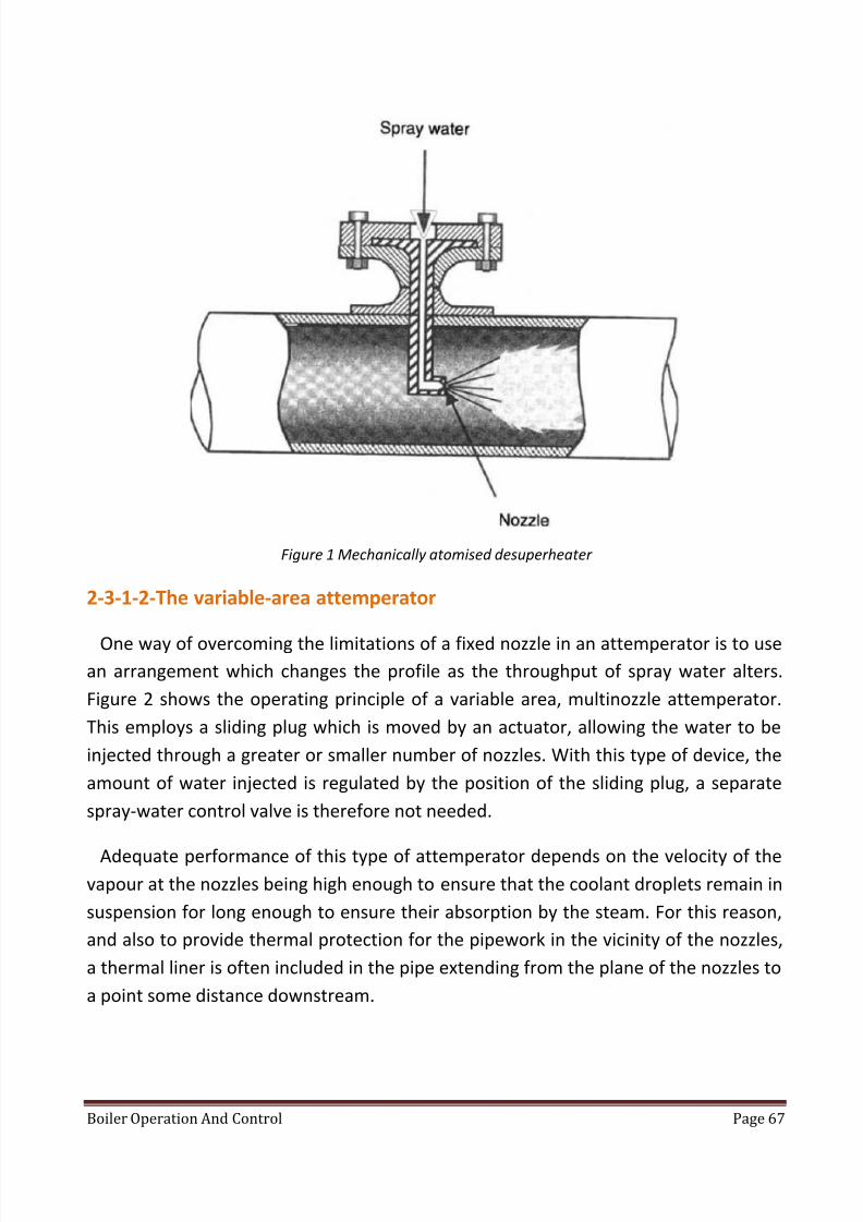
8/13/2019 Boiler Operation and Control
http://slidepdf.com/reader/full/boiler-operation-and-control 67/99
Boiler Operation And Control Page 67
Figure 1 Mechanically atomised desuperheater
2-3-1-2-The variable-area attemperator
One way of overcoming the limitations of a fixed nozzle in an attemperator is to use
an arrangement which changes the profile as the throughput of spray water alters.
Figure 2 shows the operating principle of a variable area, multinozzle attemperator.
This employs a sliding plug which is moved by an actuator, allowing the water to be
injected through a greater or smaller number of nozzles. With this type of device, the
amount of water injected is regulated by the position of the sliding plug, a separate
spray-water control valve is therefore not needed.
Adequate performance of this type of attemperator depends on the velocity of the
vapour at the nozzles being high enough to ensure that the coolant droplets remain in
suspension for long enough to ensure their absorption by the steam. For this reason,
and also to provide thermal protection for the pipework in the vicinity of the nozzles,
a thermal liner is often included in the pipe extending from the plane of the nozzles to
a point some distance downstream.

8/13/2019 Boiler Operation and Control
http://slidepdf.com/reader/full/boiler-operation-and-control 68/99
Boiler Operation And Control Page 68
The accuracy of control and the turndown range available from a multi-nozzle
attemperator is considerably greater than that of a single nozzle version, allowing the
steam temperature to be controlled to + 5.5°C over a flow range of 40: 1.
2-3-1-3-The variable-annulus desuperheater
Another way of achieving accurate control of the steam temperature over the
widest possible dynamic range is provided by the variable-annulus desuperheater
(VAD) (produced by Copes-Vulcan Limited, Road Two, Winsford Industrial Estate,
Winsford, Cheshire, CW7 3QL.). Here, the approach contour of the VAD head is such
that when the inlet steam flows through an annular ring between the spray head and
the inner wall of the steam pipe its velocity is increased and the pressure slightlyreduced. The 140 Power-plant control and instrumentation coolant enters at this
point and undergoes an instant increase in velocity and a decrease in pressure,
causing it to vapourise into a micron-thin layer which is stripped offthe edge of the
spray head and propelled downstream.
The stripping action acts as a barrier which prevents the coolant from impinging on
the inner wall of the steam pipe. The downstream portion of the VAD head is
contoured, creating a vortex zone into which any unabsorbed coolant is drawn,
Figure 2 Principle of a multi nozzle desuperheater

8/13/2019 Boiler Operation and Control
http://slidepdf.com/reader/full/boiler-operation-and-control 69/99
Boiler Operation And Control Page 69
exposing it to a zone of low pressure and high turbulence, which therefore causes
additional evaporation.
Due to the Venturi principle, the pressure of the cooled steam is quickly restored
downstream of the vena contracta point, resulting in a very low overall loss of
pressure.
An advantage of the VAD is that, due to the coolant injection occurring at a point
where the steam pressure is lowered, the pressure of the spray water does not have
to be significantly higher than that of the steam.
2-3-1-4-Other types of attemperator
At least two other designs of attemperator will be encountered in power station
applications. The vapour-atomising design mixes steam with the cooling water, thus
ensuring more effective break-up of the water droplets and shrouding the atomised
droplets in a sheath of steam to provide rapid attemperation.
Variable-orifice attemperators include a freely floating plug which is positioned above
a fixed seat--a design that generates high turbulence and more efficient
attemperation. The coolant velocity increases simultaneously with the pressure drop,
instantly vaporising the liquid. Because of the movement of the plug, the pressure
drop across the nozzle remains constant (at about 0.2 bar). The design of this type of
attemperator is so efficient that complete mixing of the coolant and the steam is
provided within 3 to 4 m of the coolant entry point, and the temperature can be
controlled to __+ 2.5 °C, theoretically over a turndown range of 100: 1.
Because the floating plug moves against gravity, this type of attemperator must be
installed in a vertical section of pipe with the steam through it travelling in an upward
direction. However, because of the efficient mixing of steam and coolant, it is
permissible to provide a bend almost immediately after the device. Figure 3 shows a
typical installation.

8/13/2019 Boiler Operation and Control
http://slidepdf.com/reader/full/boiler-operation-and-control 70/99
Boiler Operation And Control Page 70
Figure 3 Variable-orifice attemperator installation

8/13/2019 Boiler Operation and Control
http://slidepdf.com/reader/full/boiler-operation-and-control 71/99
Boiler Operation And Control Page 71
Location of temperature sensors: Because the steam and water do not mix
immediately at the plane of the nozzle or nozzles, great care must be taken to locate
the temperature sensor far enough downstream of the attemperator for the
measurement to accurately represent the actual temperature of the steam entering
the next stage of tube banks. Direct impingement of spray water on the temperature
sensor will result in the final steam temperature being higher than desired. Figure 4
shows a typical installation, in this case for a variable-annulus desuperheater.
Figure 4 a typical installation

8/13/2019 Boiler Operation and Control
http://slidepdf.com/reader/full/boiler-operation-and-control 72/99
Boiler Operation And Control Page 72
2-3-2-Temperature control with tilting burners
The burning fuel in a corner-fired boiler forms a large swirling fireball which can be
moved to a higher or lower level in the furnace by tilting the burners upwards or
downwards with respect to a mid position. The repositioning of the fireball changes
the pattern of heat transfer to the various banks of superheater tubes and this
provides an efficient method of controlling the steam temperature, since it enables
the use of spray water to be reserved for fine-tuning purposes and for emergencies. In
addition, the tilting process provides a method of controlling furnace exit
temperatures.
With such boilers, the steam temperature control systems become significantly
different from those of boilers with fixed burners. The boiler designer is able to define
the optimum angular position of the burners for all loads, and the control engineer
can then use a function generator to set the angle of tilt over the load range to match
this characteristic. A temperature controller trims the degree of tilt so that the correct
steam temperature is attained.
2-3-3-Controlling the temperature of reheated steam
In boilers with reheat stages, changes in firing inevitably affect the temperature of
both the reheater and the superheater. If a single control mechanism were to be used
for both temperatures the resulting interactions would make control-system tuning
difficult, if not impossible, to optimize. Such boilers therefore use two or more
methods of control.
Because of the lower operating pressure of reheat steam systems, the
thermodynamic conditions are significantly different from those of superheaters, and
the injection of spray water into the reheater system has an undue effect on the
efficiency of the plant. For this reason, it is preferable for the reheat stages to be
controlled by tilting burners (if these are available) or by apportioning the flow of hot
combustion gases over the various tube banks. However, if the superheat
temperature is controlled by burner tilting, gas apportioning or spray attemperation
must then be used for the reheat stages.
In boilers with fixed burners, steam-temperature control may be achieved by
adjusting the opening of dampers that control the flow of the furnace gases across the

8/13/2019 Boiler Operation and Control
http://slidepdf.com/reader/full/boiler-operation-and-control 73/99
Boiler Operation And Control Page 73
various tube banks. In some cases two separate sets of dampers are provided: one
regulating the flow over the superheater banks, the other controlling the flow over
the reheater banks.
Between them, these two sets of dampers deal with the entire volume of
combustion gases passing from the furnace to the chimney. If both were to be closed
at the same time, the flow of these gases would be severely restricted, leading to the
possibility of damage to the structure due to over pressurization. For this reason the
two sets are controlled in a so-called 'split-range' fashion, with one set being allowed
to close only when the other has fully opened.
These dampers provide the main form of control, but the response of the system is
very slow, particularly with large boilers, where the temperature response to changes
in heat input exhibits a second-order lag of almost two minutes' duration. For this
reason, and also to provide a means of reducing the temperature of the reheat steam
in the event of a failure in the damper systems, spray attemperation is provided for
emergency cooling.
The spray attemperator is shut unless the temperature at the reheater outlet
reaches a predetermined high limit. When this limit is exceeded, the spray valve is
opened. In this condition, the amount of water that is
injected is typically controlled in relation to the temperature at the reheater inlet, to
bring the exit temperature back into the region where gas-apportioning or burner
tilting can once again be effective. The relationship between the cold reheat
temperature and the required spray water flow can be defined by the boiler designer
or process engineer.
If a turbine trip occurs the reheat flow will collapse. In this situation the reheatsprays must be shut immediately in order to prevent serious damage being caused by
the admission of cold spray water to the turbine.
Spray attemperators for reheat applications
At first, it may seem that reheat spray-water attemperator systems should be similar
to those of the superheater. This is untrue, because reheat attemperators have to
cope with the lower steam pressure in this section of the boiler, which renders the
pressure of the water at the discharge of the feed pumps too high for satisfactory

8/13/2019 Boiler Operation and Control
http://slidepdf.com/reader/full/boiler-operation-and-control 74/99
Boiler Operation And Control Page 74
operation. Although a pressure-reducing valve could be introduced into the spray-
water line, this would be an expensive solution whose long-term reliability would not
be satisfactory because of the severe conditions to which such a valve would be
subjected. A better solution would be to derive the supply from the feed-pump inlet.
In some cases, even this is ineffective, and separate pump sets have to be provided
for the reheat sprays.
(A) Gas recycling
Where boilers are designed for burning oil, or oil and coal in combination, they are
frequently provided with gas-recirculation systems, where the hot gases exiting the
later stages of the boiler are recirculated to the bottom part of the furnace, close to
the burners. This procedure increases the mass-flow of gas over the tube banks, and
therefore increases the heat transfer to them.
Because the gas exiting the furnace is at a low pressure, fans have to be provided to
ensure that the gas flows in the correct direction. Controlling the flow of recycled
gases provides a method of regulating the temperature of the superheated and
reheated steam, but interlocks have to be provided to protect the fan against high-
temperature gases flowing in a reverse direction from the burner area if the fan is
stopped or if it trips.

8/13/2019 Boiler Operation and Control
http://slidepdf.com/reader/full/boiler-operation-and-control 75/99
Boiler Operation And Control Page 75
2-4-Boiler pressure control
In a typical generating station will perform the following functions:
To control boiler pressure under normal operating conditions to a specified setpoint.
To allow warm-up or cool-down of the heat transport system at a controlled
rate.
Since, under saturated conditions, steam pressure and temperature are uniquely
related, boiler pressure is used to indicate the balance between reactor heat output
and steam loading conditions.
Steam pressure measurement is used since it provides a faster response than a
temperature measurement.
The Boiler Pressure Control is a digital control loop application with a sampling period
every 2 seconds.
Basic Principles
A steam generator (boiler) is simply a heat exchanger and as such it obeys the
standard heat transfer relationship from one side of the boiler (tubes side) to the
other (shell-side).
Standard Heat transfer relationship can be described as:
Q = U. A. D T
where:
Q = the rate of heat exchange from the HTS to the boiler water (kJ/s).
U = heat transfer coefficient of the tubes (kJ/s/m2)
A = tube area (m2)
D T = temperature difference between HTS and steam generator inventory.
A and U are a function of boiler design and therefore Q is proportional to D T.

8/13/2019 Boiler Operation and Control
http://slidepdf.com/reader/full/boiler-operation-and-control 76/99
Boiler Operation And Control Page 76
If reactor power output increases, then more heat must be transferred to the boiler
water. Q has to rise, therefore D T must also increase.
This increase in D T can be achieved by either allowing the average HTS temperature
to increase as reactor power increases (as is the case for a pressurize installation) or
by arranging that the boiler Pressure falls, and therefore boiler temperature falls, as
reactor power increases (as is the case for a Solid HTS designs with no pressurize).
For all units designed with a pressurize, the first method is employed. Whereas for
units without Pressurize, the second method is used.

8/13/2019 Boiler Operation and Control
http://slidepdf.com/reader/full/boiler-operation-and-control 77/99
Boiler Operation And Control Page 77
2-4-1-Boiler pressure control operation for units having a pressurize
Under normal operating conditions, BPC manipulates the reactor power output in
order to control boiler pressure to the set point. The turbine/generator, which is the
heat sink for the boilers, is controlled to an operator specified set point.
"Alternate" or “Reactor Leading” Operation
• If the unit is operating in the reactor leading mode - at low power conditions - the
reactor power set point is specified by the operator.
• Boiler pressure is then controlled to its set point by manipulation of the steam
loads, i.e., turbine and steam discharge valves.
Steam Discharge Valve Control
The Atmospheric Steam Discharge Valves (ASDV) and Condenser Steam Discharge
Valves (CSDV) are, under normal operating conditions, closed due to the introduction
of a bias signal.

8/13/2019 Boiler Operation and Control
http://slidepdf.com/reader/full/boiler-operation-and-control 78/99
Boiler Operation And Control Page 78
If, for any reason, the boiler pressure rises above its set point by 70 kPa the
ASDVs will open.
If the rise in boiler pressure is greater than 125 kPa above set point the CSDVswill start to open.
If the positive boiler pressure error is not corrected by the ASDVs and CSDVs a
reactor setback will be initiated to correct the thermal mismatch (i.e. correct
both the demand and the supply).

8/13/2019 Boiler Operation and Control
http://slidepdf.com/reader/full/boiler-operation-and-control 79/99
Boiler Operation And Control Page 79
2-4-2-Boiler pressure control operation for Units without a Pressurize
• Units with only feed and bleed systems for Heat Transport pressure control are
normally run as base load, reactor leading, stations.
• The response of the Heat Transport System to transients caused by power
maneuvering is very limited.
• The Boiler Pressure Control System has a role in limiting the potential swell and
shrink of the HTS inventory by maintaining the HTS average temperature essentially
constant over the full operating range.
To control the boiler pressure, (the controlled variable) the
following manipulated variables are used:
(a) Reactor Power
(b) Turbine Steam Flow
(c) Steam Reject Valve (SRV) Steam Flow
• The boiler pressure will be decreased from 5 MPa to 4 MPa as unit power is raised
from 0 to 100% full power (this is to minimize HTS temperature changes).
• This is also the turbine operating ramp. The SRV set point is a parallel ramp set 100
kPa higher than the turbine ramp.
• Should the boiler pressure rise by more than 100 kPa excess pressure will be
released by the small SRVs.
• If the positive pressure transient is not corrected by the small SRVs the large SRVs
will start to open. Opening of the large SRVs will initiate a reactor setback.

8/13/2019 Boiler Operation and Control
http://slidepdf.com/reader/full/boiler-operation-and-control 80/99
Boiler Operation And Control Page 80
• If the boiler pressure falls below the turbine set point the speeder gear will run back
to a point where the decreased turbine power will be matched.

8/13/2019 Boiler Operation and Control
http://slidepdf.com/reader/full/boiler-operation-and-control 81/99
Boiler Operation And Control Page 81
2-4-3-Boiler Pressure Response to A Requested Increase in Electrical
Output
• A request for increased electrical output will create an error signal between the
existing output and the new set point.
• This error signal will cause the speeder gear to run up and thus increase the steam
flow to the turbine.
• This increased steam flow will result in an increased electrical output and eliminate
the electrical error which had been created.
• However, the increased steam flow will inevitably cause boiler pressure to fall.
• The increased governor valve opening results in an increased steam pressure on the
turbine side of the governor valve.
• This pressure increase is used as a feed forward signal which can be use d to modify
the reactor power set point in advance of the negative boiler pressure error
developing.
• In practice the feed forward signal will limit the size of the negative boiler pressure
transient but is unable to eliminate it completely.
• The resulting drop in boiler pressure is used as a feedback signal to the boiler
pressure control program. This will cause a further adjustment to be made to reactor
power output and thus return the boiler pressure to its set point.

8/13/2019 Boiler Operation and Control
http://slidepdf.com/reader/full/boiler-operation-and-control 82/99
Boiler Operation And Control Page 82
2-5-Control devices
The purpose of the control system is to start, operate, and shut down the combustion
process and any related auxiliary processes safely, reliably, and efficiently.
A combustion system typically includes a fuel supply, a combustion air supply, and an
ignition system, all of which come together at one or more burners. During system
start-up and at various times during normal operation, the control system will need to
verify or change the status of these systems. During system operation, the control
system will need various items of process information to optimize system efficiency.
Additionally, the control system monitors all safety parameters at all times and will
shut down the combustion system if any of the safety limits are not satisfied.
2-5-1-Control platforms
The control platform is the set of devices that monitors and optimizes the process
conditions, executes the control logic, and controls the status of the combustion
system.
2-5-1-1-Relay System
A relay consists of an electromagnetic coil and several attached switch contacts that
open or close when the coil is energized or de-energized. A relay system consists of a
number of relays wired together in such a way that they execute a logical sequence.
For example, a relay system may define a series of steps to start up the combustion
process. Relays can tell only if something is on or off and have no analog capability.
They are generally located in a local control panel.
Advantages of relays
Relays have several advantages. They are simple, easily tested, reliable, and well-
understood devices that can be wired together to make surprisingly complex systems.
They are modular, easily replaced, and inexpensive. They can be configured in fail-safe
mode so that if the relay itself fails, combustion system safety is not compromised.
Disadvantages
There are also a few disadvantages of relays. Once a certain complexity level isreached, relay systems can quickly become massive. Although individual relays are

8/13/2019 Boiler Operation and Control
http://slidepdf.com/reader/full/boiler-operation-and-control 83/99
Boiler Operation And Control Page 83
very reliable, a large control system with hundreds of relays can be very unreliable.
Relays also take up a lot of expensive control panel space. Because relays must be
physically rewired to change the operating sequence, system flexibility is poor.
2-5-1-2-Burner Controller
A variety of burner controllers is available from several different vendors. They are
prepackaged, hardwired devices in different configurations to operate different types
of systems. A burner controller will execute a defined sequence and monitor defined
safety parameters. They are generally located in a local control panel. Like relays, they
generally have no analog capability.
Advantages of burner controllers include the fact that they are generally inexpensive,compact, simple to hook up, require no programming, and are fail-safe and very
reliable. They are often approved for combustion service by various safety agencies
and insurance companies.
There are also some disadvantages. Burner controllers cannot control combustion
systems of much complexity. System flexibility is nonexistent. If it becomes necessary
to change the operating sequence, the controller must be rewired or replaced with a
different unit.
2-5-1-3-Programmable Logic Controller (PLC)
A programmable logic controller (PLC) is a small, modular computer system that
consists of a processing unit and a number of input and output modules that provide
the interface to the combustion components. PLCs are usually rack-mounted, and
modules can be added or changed. There are many types of modules available. Unlike
the relays and burner controllers above, they have analog control capability. They aregenerally located in a local control panel.
PLCs have the advantage of being a mature technology. They have been available for
more than 20 years. Simple PLCs are inexpensive and PLC prices are generally very
competitive. They are compact, relatively easy to hook up, and, because they are
programmable, they are supremely flexible. They can operate systems of almost any
complexity level. PLC reliability has improved over the years and is now very good.

8/13/2019 Boiler Operation and Control
http://slidepdf.com/reader/full/boiler-operation-and-control 84/99
Boiler Operation And Control Page 84
Disadvantages of PLCs include having to write software for the controller. Coding can
be complex and creates the possibility of making a programming mistake, which can
compromise system safety. The PLC can also freeze up, much like a desktop computer
freezes up, where all inputs and outputs are ignored and the system must be reset in
order to execute logic again. Because of this possibility, standard PLCs should never be
used as a primary safety device. Special types of redundant or fault-tolerant PLCs are
available that are more robust and generally accepted for this service, but they are
very expensive and generally difficult to implement.
2-5-1-4-Distributed Control System (DCS)
A distributed control system (DCS) is a larger computer system that can consist of a
number of processing units and a wide variety of input and output interface devices.
Unlike the other systems described above, when properly sized, a DCS can also control
multiple systems and even entire plants. The DCS is generally located in a remote
control room, but peripheral elements can be located almost anywhere.
DCSs have been around long enough to be a mature technology and are generally well
understood.
They are highly flexible and are used for both analog and discrete (on –off ) control.
They can operate systems of almost any level of complexity and their reliability is
excellent.
However, DCSs are often difficult to program. Each DCS vendor has a proprietary
system architecture, so the hardware is expensive and the software is often different
from any other vendor’s software. Once a commitment is made to a particular DCS
vendor, it is extremely difficult to change to a different one.
2-5-1-5-Hybrid Systems
If you could combine several of the systems listed above and build a hybrid control
system, the advantages of each system could be exploited. In practice, that is what is
usually done. A typical system uses relays to perform the safety monitoring, a PLC to
do the sequencing, and either dedicated controllers or an existing DCS for the analog

8/13/2019 Boiler Operation and Control
http://slidepdf.com/reader/full/boiler-operation-and-control 85/99
Boiler Operation And Control Page 85
systems control. Sometimes, the DCS does both the sequencing and the analog
systems control, and the safety monitoring is done by a fault-tolerant logic system.
Most approval agencies and insurers require the safety monitoring function to be
separate from either of the other functions.

8/13/2019 Boiler Operation and Control
http://slidepdf.com/reader/full/boiler-operation-and-control 86/99
Boiler Operation And Control Page 86

8/13/2019 Boiler Operation and Control
http://slidepdf.com/reader/full/boiler-operation-and-control 87/99
Boiler Operation And Control Page 87
When we control burners of boilers, we keep 2 bounds in our consideration;
1- If the amount of fuel burned is more than required duty, overheating will occur.
2- If the omount of fuel burned is less than required, drop in power will happen. If
we connect the boiler to turbine, it will make the turbine work in wet region.
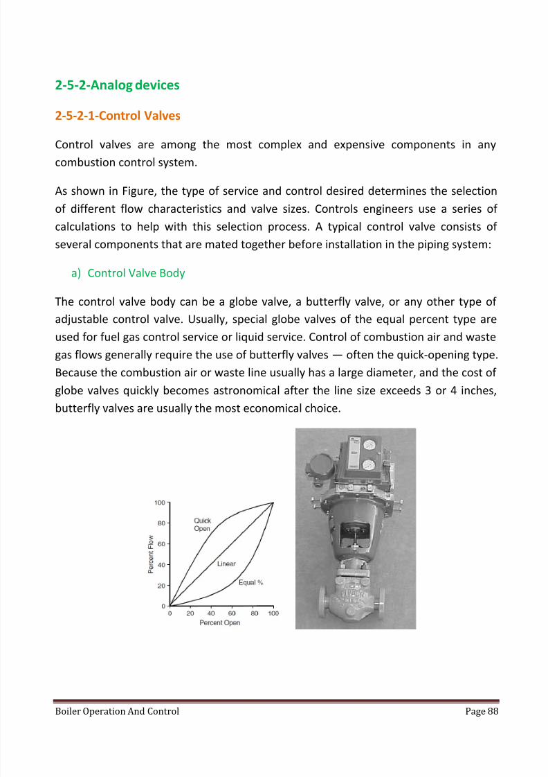
8/13/2019 Boiler Operation and Control
http://slidepdf.com/reader/full/boiler-operation-and-control 88/99
Boiler Operation And Control Page 88
2-5-2-Analog devices
2-5-2-1-Control Valves
Control valves are among the most complex and expensive components in any
combustion control system.
As shown in Figure, the type of service and control desired determines the selection
of different flow characteristics and valve sizes. Controls engineers use a series of
calculations to help with this selection process. A typical control valve consists of
several components that are mated together before installation in the piping system:
a) Control Valve Body
The control valve body can be a globe valve, a butterfly valve, or any other type of
adjustable control valve. Usually, special globe valves of the equal percent type are
used for fuel gas control service or liquid service. Control of combustion air and waste
gas flows generally require the use of butterfly valves — often the quick-opening type.
Because the combustion air or waste line usually has a large diameter, and the cost of
globe valves quickly becomes astronomical after the line size exceeds 3 or 4 inches,
butterfly valves are usually the most economical choice.

8/13/2019 Boiler Operation and Control
http://slidepdf.com/reader/full/boiler-operation-and-control 89/99
Boiler Operation And Control Page 89
b) Actuator
The actuator supplies the mechanical force to position the valve for the desired flow
rate. For control applications, a diaphragm actuator is preferred because, compared
to a piston-type actuator, it has a relatively large pressure-sensitive area and a
relatively small frictional area where the stem is touching the packing. This ensures
smooth operation, precision, and good repeatability.
Proper selection of the actuator must take into account valve size, air pressure,
desired failure mode, process pressure, and other factors. Actuators are usually
spring-loaded and single-acting, with control air used on one side of the diaphragm
and the spring on the other. The air pressure forces the actuator to move against the
spring.
If air pressure is lost, the valve fails to the spring position thus, the actuator is chosen
carefully to fail to a safe position (i.e., closed for fuel valves, open for combustion air
valves).
c) Current-to-Pressure Transducer
The current-to-pressure transducer, usually called the I/P converter, takes the 24 VDC
(4 to 20 milliamps) signal from the controller and converts it into a pneumatic signal.
The signal causes the diaphragm of the actuator to move to properly position the
control valve.
d) Positioner
The positioner is a mechanical feedback device that senses the actual position of the
valve as well as the desired position of the valve. It makes small adjustments to the
pneumatic output to the actuator to ensure that the desired and the actual position
are the same.
e) Three-Way Solenoid Valve
When energized, the three-way solenoid valve admits air to the actuator. When de-
energized, it dumps the air from the actuator. Because single-acting actuators are
generally used, the spring in the actuator forces the valve either fully open or fully
closed, depending on the engineer’s choice of failure modes when specifying thevalve. Obviously, a control valve that supplies fuel gas to a combustion system should

8/13/2019 Boiler Operation and Control
http://slidepdf.com/reader/full/boiler-operation-and-control 90/99
Boiler Operation And Control Page 90
fail closed, while the control valve that supplies combustion air to the same system
should fail open.
f) Mechanical Stops
Mechanical stops are used to limit how far open or shut a control valve can travel. If it
is vital that no more than a certain amount of fluid ever enters a downstream system,
an “up” stop is set. If it is necessary to ensure a certain minimum flow, for cooling
purposes for example, a “down” stop is set. In the case of a fuel supply control valve,
the “down” stop is set so that during system lightoff, an amount of fuel ideal for
smooth and reliable burner lighting is supplied. After a defined settling interval,
usually 10 seconds, the three-way solenoid valve is energized and normal control
valve operation is enabled.
2-5-2-2-Thermocouples
Whenever two dissimilar metals come into contact, current flows between the metals
and the magnitude of that current flow and the voltage driving it, vary with
temperature. This phenomenon is called the Seebeck effect.
If both of the metals are carefully chosen and are of certain known alloy
compositions, the voltage will vary in a nearly linear manner with temperature over
some known temperature range. Because the temperature and voltage ranges vary
depending on the materials employed, engineers use different types of
thermocouples for different situations. In combustion applications, the “K” type
thermocouple (0 to 2400°F or−18 to 1300°C) is usually used. When connecting a
thermocouple to a transmitter, the transmitter should be set up for the type of
thermocouple employed.
Installing thermocouples in a protective sheath known as a thermowell prevents the
sensing element from suffering the corrosive or erosive effects of the process being
measured. However, a thermowell also slows the response of the instrument to
changing temperature and should be used with care.

8/13/2019 Boiler Operation and Control
http://slidepdf.com/reader/full/boiler-operation-and-control 91/99
Boiler Operation And Control Page 91
Figure 1 thermo couple
2-5-2-3-Velocity Thermocouples
Also known as suction pyrometers, the design of velocity thermocouples attempts to
minimize the inaccuracies in temperature measurement caused by radiant heat.
Inside a combustor, the thermocouple measures the gas temperature. However, the
large amount of heat radiated from the hot surroundings significantly affects the
measurement. A velocity thermocouple shields the thermocouple from radiant heat
by placing it in one or more concentric hollow pipes.
Hot gas is induced to flow across the thermocouple, producing a gas temperature
reading without a radiant component.

8/13/2019 Boiler Operation and Control
http://slidepdf.com/reader/full/boiler-operation-and-control 92/99
Boiler Operation And Control Page 92
2-5-2-4-Resistance Temperature Detectors (RTDs)
Resistance of any conductor increases with temperature. For a specific material of
known resistance, it is possible to infer the temperature. Similar to the thermocouplesdescribed above, the linearity of the result depends on the materials chosen for the
detector and their alloy composition. Engineers sometimes use RTDs instead of
thermocouples when higher precision is desired. Platinum is a popular material for
RTDs because it has good linearity over a wide temperature range. Like
thermocouples, installation of RTDs in thermowells is common.

8/13/2019 Boiler Operation and Control
http://slidepdf.com/reader/full/boiler-operation-and-control 93/99
Boiler Operation And Control Page 93
2-5-2-5-Pressure Transmitters
A pressure transmitter is usually used to provide an analog pressure signal. These
devices use a diaphragm coupled to a variable resistance, which modifies the 24 VDC
loop current (4 to 20 milliamps) in proportion to the range in which it is calibrated. In
recent years, these devices have become enormously more accurate and
sophisticated, with onboard intelligence and self calibration capabilities.
They are available in a wide variety of configurations and materials and can be used in
almost any service. It is possible to check and reconfigure these “smart” pressure
transmitters remotely with the use of a handheld communicator.
2-5-2-6-Flow Meters
There are many different types of flow meters and many reasons to use one or
another for a given application. The following is a list of several of the more common
types of flow meters, how they work, and where they are used.

8/13/2019 Boiler Operation and Control
http://slidepdf.com/reader/full/boiler-operation-and-control 94/99
Boiler Operation And Control Page 94
2-5-2-6-1-Vortex Shedder Flow Meter
A vortex shedder places a bar in the path of the fluid. As the fluid goes by, vortexes
(whirlpools) form and break off constantly. An observation of the water swirling on
the downstream side of bridge pilings in a moving stream reveals this effect. Each
time a vortex breaks away from the bar, it causes a small vibration in the bar. The
frequency of the vibration is proportional to the flow.
Vortex shedders have a wide range, are highly accurate, reasonably priced, highly
reliable, and useful in liquid, steam, or gas service.
2-5-2-6-2-Magnetic Flow Meter
A magnetic field, a current carrying conductor, and relative motion between the both
creates an electrical generator.

8/13/2019 Boiler Operation and Control
http://slidepdf.com/reader/full/boiler-operation-and-control 95/99
Boiler Operation And Control Page 95
In the case of a magnetic flow meter, the meter generates the magnetic field and the
flowing liquid supplies the motion and the conductor. The voltage produced is
proportional to the flow. These meters are highly accurate, very reliable, have a wide
range, but are somewhat expensive. They are useful with highly corrosive or even
gummy fluids as long as the fluids are conductive. Only liquid flow is measured.
2-5-2-6-3-Orifice Flow Meter
Historically, almost all flows were measured using this method and it is still quite
popular. Placing the orifice in the fluid flow causes a pressure drop across the orifice.
A pressure transmitter mounted across the orifice calculates the flow from the
amount of the pressure drop. Orifice meters are very accurate but have a narrowrange. They are reasonably priced, highly reliable, and are useful in liquid, steam, or
gas service.

8/13/2019 Boiler Operation and Control
http://slidepdf.com/reader/full/boiler-operation-and-control 96/99
Boiler Operation And Control Page 96
2-5-2-6-4-Coriolis Flow Meter
The Coriolis flow meter is easily the most complex type of meter to understand. The
fluid runs through a U-shaped tube that is being vibrated by an attached transducer.The flow of the fluid will cause the tube to try to twist because of the Coriolis force.
The magnitude of the twisting force is proportional to flow. These meters are highly
accurate and have a wide range. They are generally more expensive than some other
types.

8/13/2019 Boiler Operation and Control
http://slidepdf.com/reader/full/boiler-operation-and-control 97/99
Boiler Operation And Control Page 97
2-5-2-6-5-Ultrasonic Flow Meter
When waves travel in a medium (fluid), their frequency shifts if the medium is in
motion relative to the wave source.
The magnitude of the shift, called the Doppler effect, is proportional to the relative
velocity of the source and the medium. The ultrasonic meter generates ultrasonic

8/13/2019 Boiler Operation and Control
http://slidepdf.com/reader/full/boiler-operation-and-control 98/99
Boiler Operation And Control Page 98
sound waves, sends them diagonally across the pipe, and computes the amount of
frequency shift.
These meters are reasonably accurate, have a fairly wide range, are reasonably priced,
and are highly reliable. Ultrasonic meters work best when there are bubbles or
particulates in the fluid.
2-5-2-6-6-Turbine Flow Meters
A turbine meter is a wheel that is spun by the flow of fluid past the blades. A magnetic
pickup senses the speed of the rotation, which is proportional to the flow. These
meters can be very accurate but have a fairly narrow range. They must be very
carefully selected and sized for specific applications. They are reasonably priced and
fairly reliable. They are used in liquid, steam, or gas service.

8/13/2019 Boiler Operation and Control
http://slidepdf.com/reader/full/boiler-operation-and-control 99/99
2-5-2-6-7-Positive Displacement Flow Meters
Positive displacement flow meters generally consist of a set of meshed gears or lobes
that are closely machined and matched to each other. When fluid is forced through
the gears, a fixed amount of the fluid is allowed past for each revolution. Counting the
revolutions reveals the exact amount of flow. These meters are extremely accurate
and have a wide range. Because there are moving parts, the meters must bemaintained or they can break down or jam. They also cause a large pressure drop,
which can be important for certain applications.