Embed Size (px)
Citation preview
Industrial Diesel Incorporated
8705 Harmon Road
Fort Worth, Texas 76177
(800) 323-3659
www.industrialdiesel.net
TECHNICAL SPECIFICATION
BBBO
OODDDY
YYLLLOOOA
AADDD
111000000---FFFBBBT
TT BBBL
LLEEENNND
DDEEERRR
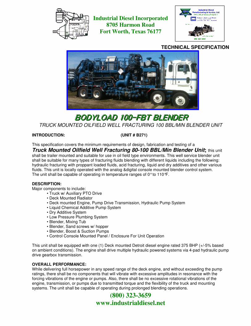
TRUCK MOUNTED OILFIELD WELL FRACTURING 100 BBL/MIN BLENDER UNIT
INTRODUCTION: (UNIT # B271) This specification covers the minimum requirements of design, fabrication and testing of a
Truck Mounted Oilfield Well Fracturing 80-100 BBL/Min Blender Unit; this unit
shall be trailer mounted and suitable for use in oil field type environments. This well service blender unit shall be suitable for many types of fracturing fluids blending with different liquids including the following: hydraulic fracturing with proppant loaded fluids, acid fracturing, liquid and dry additives and other various fluids. This unit is locally operated with the analog &digital console mounted blender control system. The unit shall be capable of operating in temperature ranges of 0° to 110°F. DESCRIPTION: Major components to include:
• Truck w/ Auxiliary PTO Drive • Deck Mounted Radiator • Deck mounted Engine, Pump Drive Transmission, Hydraulic Pump System • Liquid Chemical Additive Pump System • Dry Additive System • Low Pressure Plumbing System • Blender, Mixing Tub • Blender, Sand screws w/ hopper • Blender, Boost & Suction Pumps • Control Console Mounted Panel / Enclosure For Unit Operation
This unit shall be equipped with one (1) Deck mounted Detroit diesel engine rated 375 BHP (+/-5% based on ambient conditions). The engine shall drive multiple hydraulic powered systems via 4-pad hydraulic pump drive gearbox transmission. OVERALL PERFORMANCE: While delivering full horsepower in any speed range of the deck engine, and without exceeding the pump ratings, there shall be no components that will vibrate with excessive amplitudes in resonance with the forcing vibrations of the engine or pumps. Also, there shall be no excessive rotational vibrations of the engine, transmission, or pumps due to transmitted torque and the flexibility of the truck and mounting systems. The unit shall be capable of operating during prolonged blending operations.

Industrial Diesel Incorporated
8705 Harmon Road
Fort Worth, Texas 76177
(800) 323-3659
www.industrialdiesel.net
EQUIPMENT SPECIFICATIONS: This unit is truck mounted on a tandem drive axle / tandem steer axle oilfield type cab-over truck. The approximate physical dimensions of this unit are as follows: (approximate) Overall Length - 40 ft. Width - 8 ft. - 6’’ Height - 13 ft. - 2’’ Weight –58,620 Lbs. (Estimated only) CHASSIS OILFIELD TRUCK
The Kenworth cab-over truck is designed specifically for the application with the following features:
1998 Kenworth (153,586 Miles) Model Cab Over: Tandem Drive / Tandem Steer
Engine (106 Hours) Detroit Series 60, 500 BHP @ 2100 RPM
Capacity 80,000 #
Overall Length 40’
Overall Width 8’-6”
Deck Height 42’
Ground Clearance 12”
Suspension Drive / Steel Mechanical Leaf Spring
Wheels/Rims 8.25 X 22.5
Tires 11R22.5
POWER SYSTEM DRIVE / DISCHARGE DIESEL ENGINE (Truck mounted) Mounted in the truck chassis will be a Detroit Diesel Model Series 60 4-stroke diesel engine equipped with the following:
• Engine rated a minimum of 500 BHP at 2100 RPM • Air-filter, dry element, canister type with manual service indicators • Flywheel and flywheel housing dry type, for use with engine mounted Multi-speed transmission
• Manifold exhaust • Oil level dipstick • Oil pan, standard capacity • Pumps for fuel, lubricating oil, fuel transfer • Pumps, jacket water • Support, front trunnion • Thermostats and housing • Turbo charger • Vibration dampener • Shutoff group electrical (standard- analog controlled) • Alternator (12 VDC) with dedicated battery bank • Electric starter system • Lubricating oil filters, spin-on type element
COOLING SYSTEM: A vertical mounted radiator system with horizontal air discharge will be installed on the unit to include a mechanically driven fan assembly w/ remote PTO lock-in feature, completed with a water drain valve, a core

Industrial Diesel Incorporated
8705 Harmon Road
Fort Worth, Texas 76177
(800) 323-3659
www.industrialdiesel.net
guard. This radiator is designed to perform at ambient temperatures of 0° - 110° F. Separate cooling cores shall be provided as an integral part of the radiator design to include:
• Engine jacket water • Fuel cooler • Hydraulic oil cooler
TRANSMISSION: The engine shall be coupled to an Eaton Fuller Model 13-speed manual Hi/Lo transmission mounted with auxiliary hydraulic pump drive PTO system. Features include:
• Max. Net Input HP: 500 HP • Max. Input Speed: 2100 RPM • Manual Dry Clutch Driven
AUXILIARY DIESEL ENGINE (Deck mounted) Mounted on the truck chassis will be a Detroit Diesel Model 6V92TAB two-stroke oil well servicing diesel engine equipped with the following:
• Engine rated a minimum of 375 BHP at 2200 RPM • Air-filter, dry element, canister type with manual service indicators • Flywheel and flywheel housing (Industrial) dry type, for use with engine mounted pump drive gearbox transmission
• Lifting eyes • Manifold exhaust w/ stainless steel flex-joint connection • Oil level dipstick • Oil pan, standard capacity • Pumps for fuel, lubricating oil, fuel transfer • Pumps, jacket water • Support, front trunnion • Thermostats and housing • Turbo charger • Vibration dampener
• Exhaust system with industrial grade silencer with rain cap • Shutoff group electrical (standard- analog controlled) • Alternator (12 VDC) with dedicated battery bank • Electric starter system • Lubricating oil filters, spin-on type element • Webasto Diesel fired block heater system
COOLING SYSTEM: A vertical mounted radiator system with horizontal air discharge will be installed on the unit to include a mechanically driven fan assembly, completed with a water drain valve, a core guard. This radiator is designed to perform at ambient temperatures of 0° - 110° F. Separate cooling cores shall be provided as an integral part of the radiator design to include:
• Engine jacket water • Fuel cooler • Hydraulic oil cooler

Industrial Diesel Incorporated
8705 Harmon Road
Fort Worth, Texas 76177
(800) 323-3659
www.industrialdiesel.net
PUMP DRIVE GEARBOX TRANSMISSION: The engine shall be coupled to a Durst Model 12643 4-pad direct mounted hydraulic pump drive gearbox transmission system. Transmission accessories shall include: GEARBOX:
• 1.0:1 Ratio • Max. Net Input HP: 400 HP • Max. Input Speed: 2300 RPM • SAE #1, dry flywheel mounting w/ flex plate drive
ENGINE / TRANSMISSION MOUNTING: The engine shall be vibration isolated from the truck chassis by means of rubber vibration isolators and a front engine trunnion mount. This makes the engine / transmission mount combination work as a one unit. This is accomplished with a three (3)-point flexible mounting system with a single mount at the front and two flexible mounts at the rear. This type of mounting system eliminates any alignment problems on equipment where normal flexing of the frame may occur. The transmission is an integral part of the power unit assembly, therefore allowing easy access to the transmission and hydraulic pumps, filters, strainers and oil level indicators maintenance purposes. HYDRAULIC SYSTEMS: Four (4) dedicated hydraulic systems for powering the components incorporated on the unit other than truck mobility.
1. Suction C-Pump System: A closed-loop hydraulic pump is directly driven from the pump drive gearbox to hydraulically drive the Gorman-Rupp 6X12X20 centrifugal pump. This system shall be rated at 30 GPM @ 4500 PSI (approx.)
2. Sand Screw Drive System: A closed-loop hydraulic pump is directly driven from the pump drive gearbox to hydraulically drive the three (3) 14” sand screw conveyors via SAI GM2 Series motors. This system shall be rated at 30 GPM @ 5500 PSI (approx.)
3. Tub Mixing Paddle Drive System: An open-loop hydraulic pump is directly driven from the pump drive gearbox to hydraulically drive the rotating mixing paddles via a geroter type high torque, low speed motor. This system shall be rated at 40 GPM @ 3500 PSI (approx.)
4. Chemical-Additive Discharge Pump Drive System: An open-loop hydraulic pump is directly driven from the pump drive gearbox to hydraulically drive the hydraulically driven three stage liquid chemical additive pumps via a rotor type high torque, low speed motor. This system shall be rated at 10 GPM @ 2500 PSI (approx.) The discharge motor output speeds are remotely managed with the operator controlled 4-20Ma proportional valve system.
These hydraulic systems shall incorporate all equipment such as hydraulic oil tank (as required), suction filters, return line filters w/ bypass protection, relief valves w/ monitoring liquid filled gauges, pressure operated directional control valves to insure a complete and functional system. All plumbing utilized in the hydraulic system shall not exceed the radiator and component manufacturer’s recommended pressure and temperature ratings during normal operation.

Industrial Diesel Incorporated
8705 Harmon Road
Fort Worth, Texas 76177
(800) 323-3659
www.industrialdiesel.net
DISCHARGE/BOOST C-PUMP A mechanically driven Mission Magnum XP 6X12X20 centrifugal pump is connected to the discharge manifold on the road-side of the unit. The discharge pump includes the following features:
• 6X12X20 variable rate capable of 80-100 BBL/Min rate • 6” flanged discharge connection • 12” flanged suction connection • High performance self-adjusting shaft seal • Approximate weight: 475 lbs.
SUCTION C-PUMP A hydraulically driven Gorman-Rupp centrifugal pump is used connected to the blender/mixing tub to the suction manifold on the curb-side of the unit. The suction/recirculating pump includes the following features:
• 14X12X22 variable rate capable of 80-100 BBL/Min rate • 12” flanged discharge connection • 14” flanged suction connection • High performance self-adjusting shaft seal • Approximate weight: 575 lbs.
SUCTION MANIFOLD: A 12” “Log” style suction manifold is mounted on the curb-side of the unit is connected to the suction centrifugal pump inlet flanged connection. It is equipped with the following:
• Six (6) 4” Fig. 200 female threaded hose connections with manual butterfly valves and caps and chains
• Seven (7) 4” Fig. 200 female threaded connections with air actuated butterfly valves and caps and chains
• One (1) 12” air actuated isolation butterfly valve
DISCHARGE MANIFOLD: A 12” “Log” style discharge manifold is mounted on the road-side of the unit is connected to the discharge/boost centrifugal pump outlet flanged connection. It is equipped with the following:
• Six (6) 4” Fig. 200 female threaded hose connections with manual butterfly valves and caps and chains
• Seven (7) 4” Fig. 200 female threaded connections with air actuated butterfly valves and caps and chains
• One (1) 12” air actuated isolation butterfly valve
• Two (2) 12” Rosemount magnetic flow meters w/ digital readout

Industrial Diesel Incorporated
8705 Harmon Road
Fort Worth, Texas 76177
(800) 323-3659
www.industrialdiesel.net
• One (1) 3” Turbine style flow meter w/ digital readout
FLUID BLENDING/MIXING TUB A horizontal open top blending/mixing tub is mounted to the rear of the unit and includes the following:
• 5 barrel capacity
• Hydraulically driven paddle mixing system
• Tub level monitor
• Two (2) Discharge recirculating “cross-over” manifolds w/ 10” butterfly valves and air actuators
SAND HOPPER/CONVEYOR SYSTEM A vertical sand screw conveyor system is mounted at the rear of the unit to feed solid dry proppant material from an off-board supply via the open top hopper to the blender mixing tub. These screws are lowered to ground level and independently controlled by the operator. The screws are retractable for transporting the unit. This system is complete with the following:
• Three (3) 14” diameter hydraulically driven auger sand screws
• Hydraulic lift gates
• Rock screens
• Variable speed controlled SAI GM2 Series hydraulic motor drives
• 1-1/2 yard open top hopper with fold down access panel and three (3) 4” Fig 200 female threaded fluid cleanout connections
• Hydraulic lower & lift slide cylinders w/ manual control valve
• Remotely grease automatic Beka-Max grease pump system with dedicated lines to lubricated lower seals sand screw shaft end bearings

Industrial Diesel Incorporated
8705 Harmon Road
Fort Worth, Texas 76177
(800) 323-3659
www.industrialdiesel.net
LIQUID CHEMICAL ADDITIVE SYSTEM Included on the unit is a hydraulically powered liquid chemical additive pump system. This pump system allows operator controlled measured amounts of various liquid additives to be introduced into the discharge C-pump fluid stream during continuous blending operations. The system is complete as follows:
• Five (5) John Blue Co. Model DP-139 triple radial diaphragm type, hydraulic motor driven liquid chemical pumps w/ variable speed control (4-20 mA HDC variable speed proportional valves motor speed control w/ manual over-ride)
o Maximum Flow: 13.9 gpm @ 550 and 145 psi o Maximum Pressure: 580 psi o Maximum Speed: 550 rpm o Maximum Power: 5.6 hp o Weight: 30.8 lbs.
• Five (5) 2” Cam-lock liquid chemical supply hose connections DRY CHEMICAL ADDITIVE SYSTEM Included is an operator deck mounted dry chemical additive hopper for manually introducing various dry chemical additives into the blender tub during continuous tub mixing and fluid blending operation. The system includes:
• 200 Cu/In dry additive hopper capacity
• Manual isolation / metering butterfly valve
• Manual hopper cover lid LUBRICATION: A 12 VDC electrically driven Beka-Max EP-1 grease type bearing lube system is installed to provide lubrication to the three (3) lower sand screw bearings. The self-contained system ncludes the reservoir, over pressure relief, indicating lights and accessories continuously cycled and metered lubrication to each of the bearings on an adjustable, timed interval. The grease system will have adequate capacity for continuous operation up to 8 hour prior to needing a new charge of grease. Recharging is performed via externally accessible refill coupling for ease of service.

Industrial Diesel Incorporated
8705 Harmon Road
Fort Worth, Texas 76177
(800) 323-3659
www.industrialdiesel.net
CONTROL & INSTRUMENTATION SYSTEM
BLENDER CONTROL SYSTEM (AVAILABLE OPTION – PRICE ADDER APPLIES) OPERATOR CONTROL CONSOLE: The IDMS/CCG “Liberator” Blender Operator Automated Control System includes a locally deck mounted steel operator’s control console positioned for easy access and viewing of the mixing tub and other operator managed systems. The console includes an NEMA 4x interconnect enclosure isolated from the chassis and have a hinged locking door. Additional control components are mounted in various panel groups to control the truck and deck engine speed control and monitor vital pressures and temperatures. Additional gage and display panels are included for monitoring the critical blender density, pressure and flow rates of the blended fluid stream discharged down hole via the modular frac stage scheduling software and recorded within the Data Acquisition System. These systems are complete as follows: Truck Engine / Transmission Auxiliary PTO Drive System
• Engine throttle control
• Engine oil pressure
• Engine coolant temperature
• Transmission output speed
• Transmission oil temperature
• PTO Engage/Disengage indicator

Industrial Diesel Incorporated
8705 Harmon Road
Fort Worth, Texas 76177
(800) 323-3659
www.industrialdiesel.net
Deck Engine System
• Engine speed (RPM)
• Engine running hour meter
• Oil pressure
• Coolant Temperature Hydraulic Systems
• Charge Pressure
• Main Pressure
• Oil Temperature Blender / Mixing System
• Clean Fluid Flow Rate (BBL/Min)
• Discharge Slurry Fluid Flow Rate (BBL/Min)
• Tub Slurry Density (Lbs/Gal.)
• Sand Auger Speed (RPM) Liquid Chemical Additive System
• Liquid pump Speed (RPM)
• Liquid Chemical Flow Rate (GPM) Additional features included:
• Work lights
• Battery disconnect switch
• Grease lube “Auto / Manual” control toggle switch ADDITIONAL ITEMS: The blender will include a stand-alone data chart recording & logging system.

Industrial Diesel Incorporated
8705 Harmon Road
Fort Worth, Texas 76177
(800) 323-3659
www.industrialdiesel.net
UNITIZATION AND COMPLETION
DESCRIPTION
The above unit shall be fully assembled, unitized, and completed to the customer’s specifications. Note: If these items are already detailed above, they shall not be duplicated. This shall include the following items:
• Installation of all other electrical systems
• Installation of all hydraulic systems
• All steel and miscellaneous fittings to complete the unit
• All labor to complete unit
• Workmanship should be of good quality and appearance. Following is partial list of examples:
• Flame cut edges shall be ground smooth.
• Sharp corners and edges to which operators and mechanics are vulnerable shall be ground smooth.
• Bolt holes for bolts shall be drilled (not torch cut) no more than 1/8” larger than the bolt it accepts.
• Welds shall be of good quality and of sufficient strength.
• Use self-locking nuts where applicable.
• All hoses will be well supported with support type clamps.
• No sweated or brazed type hydraulic fittings will be used.
• All hose assemblies will have swivel ends.
• All hoses will be protected by well-secured rubber sleeves to prevent rubbing by frame, (as required)
• All reservoirs to be constructed of steel plate with sight level gauge, cleanouts, and vent fill cap, etc.

Industrial Diesel Incorporated
8705 Harmon Road
Fort Worth, Texas 76177
(800) 323-3659
www.industrialdiesel.net
Finish Coatings & Trim
• Level 1 (standard) Oxide primer coat and Urethane finish coat to customer’s one-color specifications.
• Level 2 (Premium) Endura Coatings 2-part epoxy primer & finish paint system, o Two (2) tone paint scheme: 5 year manufactures warranty (price adder applies)
1. Primary color: Color 1 2. Secondary color: Color 2
Completion:
• The complete function testing of the equipment. Two (2) copies of all relevant test and quality control certificates of the manufacturing and testing of all unit functions and parameters will be supplies together with two (2) copies of all required vendor and manufacturer’s test certificates in the English language.