Embed Size (px)
Citation preview

BODY ASSEMBLY PROCESS IMPROVEMENT FOR AUTOMOTIVE
INDUSTRY
MOHD NAJMI BIN MOHAMAD
A report is submitted in partial fulfillment
of the requirements for the award of the degree of
Bachelor of Mechanical Engineering with Automotive Engineering
Faculty of Mechanical Engineering
UNIVERSITI MALAYSIA PAHANG
NOVEMBER 2008
UNIVERSITI MALAYSIA PAHANG

ACKNOWLEDGEMENTS
I feel grateful to Allah S.W.T because this project has successfully completed. In
completion this final year project, I was in contact with many people that contributed
toward my understanding and problem solving. In particular, I wish to express my
sincere appreciation to my project supervisor, Ir Haji Nik Mohd Zuki B Nik Mohamad
for his guidance, advice and encouragement. Without his continued support and interest,
this thesis would not have been the same as presented here.
I am deeply thankful to En.Nik Adnan B Nik Abdullah as a manager at Body
Shop Mercedes-Benz Production (AMM) for sharing their knowledge and experience
for understanding me more about the process at body assembly. I also would like to
dedicate my appropriation and special thank to him because giving the permission to do
my case study at body assembly.
Not forgetting my friends who help me to grow further and influence my project
in order to finish this project. I appreciate very much to them because of the idea and
information given along done this project. I also would like thank to Dr. Kumaran A/L
Kadirgama who act as a co-supervisor and give a support to finish this report.
Last but not least I acknowledge without endless love and relentless support from
my family. All of them, you all have given me the inspirations and encouragement until
these days. This project definitely not exists without full encouragement from them.

ABSTRACT
An automotive body assembly system consists of many individual sub-
assemblies and sheet metal parts welded. The objective in this project is to identify the
problem that always happens in line assembly. Then improve the problem in line
assembly to overcome from the problem arise. Hence make a comparison and find a
solution about body assembly to improve the problem from the data analysis. At body
assembly process there are several problem could happen such as miss the spot part,
dent or hump, scratch, spatter burr and hole to the body during assembly. But the major
problem happen at line assembly is spot weld and men mistake. By using 4M method
which includes machine, method, material and man, this problem can be identify easily
and effected. As a result there are some problem that contributes to the problem happen
such as logistic problem which involve the wrong part delivery and wrong shipment.
Besides that, man power and workability also be the problem to the line assembly. Lack
of discipline, behaviour and competency of worker give a worse impact to the company.
Wrong workability involves many of tools, machine and man power and affected the
production and flow in line assembly. Spot welding becomes a problem when the
current voltage supply is not enough and it can work properly. Lastly jigs and fixture
need to be right servicing schedule to make sure the machine and tools are in good
condition and avoid the problem happen used it. The method were used to make the
analysis data is by making study case at AMM factory which more focus at body
assembly line and problem occur during the process. From the data collected, analysis
data can be done and improve the problem that always happen in line assembly. Hence it
gives benefit to the company either in productivity or working environment from the
solution has done.

ABSTRAK
Proses penyambungan badan kereta mempunyai banyak bahagian-bahagian
individu dan kepingan besi yang perlu di sambung. Objektif untuk projek ini ialah untuk
mengenal pasti masalah yang sering berlaku di dalam proses penyambungan. Selepas
itu, penyelesaian yang paling sesuai akan di cadangkan dalam mengatasi masalah yang
sering kali timbul. Justeru itu, perbandingan dan penyelesaian dapat di buat daripada
analisis data. Di bahagian penyambungan badan kereta masalah yang selalu terjadi
adalah seperti tersalah pateri bahagian badan,kemik, lekuk,calar dan lubang di bahagian
badan kereta yang di sambung. Tetapi masalah utama ialah spot weld dan kecuaian
pekerja. Dengan menggunakan kaedah 4M yang merangkumi mesin, kaedah, bahan
mentah dan pekerja dapat mengesan masalah dengan mudah dan cekap. Keputusan yang
dapat di lihat ialah masalah pemindahan dan pengankutan bahan yang di hantar dengan
salah dan tempat yang tidak betul. Selain itu, pekerja dan kemahiran yang ada juga
menjadi salah satu punca masalah yang sering berlaku. Kurangnya disiplin, perangai dan
komitmen yang di berikan memberi impak yang besar kepada syarikat. Salah
penggunaan alatan dan mesin akan menyebabkan masalah kepada produktiviti dan
pengeluaran produk yang di hasilkan. Spot welding menjadi masalah apabila arus yang
di bekalkan tidak mencukupi. Ini kerana ia tidak dapat berjalan dengan baik apabila arus
tidak mencukupi. Langkah-langkah yang di buat dalam menghadapi masalah ini ialah
dengan membuat kajian dan pemantauan di kilang AMM di mana pengkhususan lebih di
berikan kepada tempat penyambungan badan kereta dan masalah yang sering berlaku
ketika proses penyambungan. Dari data analisis yang di kumpul langkah-langkah untuk
mengatasi masalah yang sering berlaku dapat di cadangkan. Dengan itu, ia akan member
manfaat samaada dari segi produktiviti atau suasana pekerjaan hasil daripada langkah-
langkah yang telah di cadangkan.

TABLE OF CONTENTS
CHAPTER TITLE PAGE
TITLE i SUPERVISOR DECLARATION ii STUDENT DECLARATION iii ACKNOWLEDGEMENTS iv ABSTRACT v ABSTRAK vi TABLE OF CONTENTS vii LIST OF TABLES x LIST OF FIGURES x LIST OF SYMBOLS xii LIST OF ABBREVIATION xii LIST OF APPENDICES xii

CHAPTER 1 INTRODUCTION
1.1 Project Background 1
1.2 Problem Statement 1
1.3 Project aim and objective 2
1.4 Project Scopes 2 CHAPTER 2 LITERATURE REVIEW
2.1 Introduction 3
2.2 Spot Welding 9 2.21 Large Panel with Members and Brackets 10
2.22 Preassembled Parts 11 CHAPTER 3 METHODOLOGY
3.1 Introduction 16 3.2 Flow Chart of Methodology 16
3.3 Method 19
3.3.1 Process in assembly line 19 3.3.2 Overcome the problem arise 21 3.4 Propose Solution 22

3.5 Comparison Data 23 CHAPTER 4 RESULTS AND DISCUSSION 4.1 Introduction 25 4.2 Line assembly process result 25 4.3 Problem from Line Assembly Result 34 4.31 Human mistake 40 4.32 Machine 43 4.4 Conclusion 45
CHAPTER 5 CONCLUSION 5.1 Conclusion 46
5.2 Recommendations 47
5.3 Future recommendation 48
REFERENCES 49 APPENDIX 51

LIST OF TABLES
TABLE NO.PAGE TITLE 2.0 Activity Process in Line Assembly 7
2.1 Dimensional Accuracy in Body Assembly 14
3.1 Table of quality control at assembly line 24
LIST OF FIGURES
FIGURE NO. TITLE 2.0 An auto body assembly process 4 2.1 Body in white 5 2.2 Possible Measuring Station Locations 5 2.3 Single-sided RSW of a large panel 10 2.4 Conventional way to build package tray panels 12 2.5 Proposed way to build preassembled package tray panels 12 3.0 Flow Chart of Methodology 18 3.2 Diagram for fish bone 22 4.0 Reinforcement A and B-pillar 26 4.1 Sidewall Integral 27

4.2 Sidewall Inner 28 4.3 Sidewall outer 29 4.4 Engine comp.1 and 2 30 4.5 Main jig 32 4.6 Stud welding 33 4.7 Complete car body 34 4.80 Bar chart quality control 36 4.81 23 April 2008 37 4.82 24 April 2008 37 4.83 Problem happen in line assembly 38 4.84 Fishbone diagram for data analysis 39 4.85 Wrong delivery and shipment 41 4.86 Absent of worker 42 4.87 Spot welding 43 4.88 Electrode of spot weld 44 4.90 Quality checking for the body 51 4.91 Infrared heated for glue sealant 51 4.92 Clamp compartment 52 4.93 Clinching machine 52 4.94 Final stage of quality checking 53 4.95 Complete car of Mercedes model 53 4.96 Gantt chart FYP 1 54

4.97 Gantt chart FYP 2 55
LIST OF SYMBOL
% Percentage
LIST OF ABBREVIATION
4M Man, machine, method and material
Assy Assembly
AMM Automotive Manufacture Malaysia
LHS Left hand side
RHS Right hand side
Comp Compartment
MIG Metal inert gas
BIW Body in white
RSW Resistance spot welding
LIST OF APPENDICES
APPENDIX TITLE PAGE
A Figure 51

CHAPTER 1
INTRODUCTION
1.1 Project Background
Assembly requirements of individual components going in the sub-assembly and
accessibility of weld spots decide the numbers of stages required and weld gun style.
Welding guns are generally available in standard configurations dependent on size and
style. Special guns may be essential to meet specific requirement of body design.
Numbers of fixtures and welding guns, man power engaged and their efficiency along
with efficiency of the overall system such as maintenance, decide the production
capacity of the line.
In the body assembly there several method were used such as laser weld, tailor
welded blank and spot weld. For this report, spot weld will be taken as the main research
and case study. Resistance spot welding (RSW) is used for the fabrication of sheet metal
assemblies. The process is used extensively for joining low carbon steel components for
the bodies and chassis of automobiles, trucks, trailers, buses, mobile homes, motor
homes and recreational vehicles, and appliances and many other products.
1.2 Problem Statement
In the body assembly process there are several problem could happen. When this
happen it could stuck the process in assembly line and disturb certain department. The
major problem in the body assembly is spot weld gun and human mistake. Everyday

there are always have problems regarding this two factor such as miss the spot part, dent
or hump, scratch, spatter burr and hole to the body during assembly. For analysis
purpose, this problem will delay the time and production to recover it back. Hence, this
research will help by making the analysis and case study at the body assembly by
proposing a solution to avoid the problem or reduce it from happening.
1.3 Objective and Project Aim
The aim of this project is to reduce the problem occurs during body assembly
process and decrease the possibility that mistake could happen during work. The aim can
be achieve by objective below:
I. Identify the problem that always happen in line assembly
II. Improve the problem in line assembly
III. Make a comparison and find a solution in line assembly
1.4 Project Scope
The scope of this project, more focus on E-class Mercedes car assembly at
Automotive Manufacture Malaysia (AMM) factory at Pekan. Collecting the data have be
done by visited the AMM factory for several time where all the data were recorded for
used in this report. The report cover several scope:
I. Make a analysis in the line assembly
II. Study function of spot weld gun
III. Improve the problem in line assembly

CHAPTER 2
LITERATURE REVIEW 2.1 Introduction With increased competition in the automobile market, more attention has been
given to managing variations in automobile body assembly processes. Dimensional
variation affects fit quality and functionality. For example, variations in a body-in-white
(BIW) can ultimately cause poor sealing, undue effort required for door closing, water
leaks, excessive wind noise, prolonged time-to-market and added manufacturing costs.
Typically, the automobile body assembly process comprises numerous steps, utilizing
300–500 compliant sheet metal parts, 50–120 assembly stations and 3000–6000 spot
welds. Each step in the process is capable of contributing a degree of variation. Those
variations in turn act on one another to compound distortion in the final BIW. The
complexity of this interaction places severe demands on the existing methods of
simulation, which currently fall far short of satisfaction. (Min Hu, Zhongqin Lina et.al,
2001)
An automotive body assembly system consists of many individual subassemblies
and sheet metal parts welded at more than 200 stations. Dimensional variation in the
final body is accumulated as sheet metal parts are assembled at each level of the system.
In designing such a system, engineers are interested in predicting how variation
propagates through the system so that process problems can be solved early. During the
launch of the manufacturing system, engineers are interested in identifying the sources
of variation quickly so that quality products can be produced in the shortest possible
time. Traditional variation simulation techniques were developed mainly for simulation
of product variations and are based on rigid body assumptions. They are not applicable
for compliant sheet metal assembly because parts can deform, causing changes in

dimensions during assembling. In addition, existing diagnostic tools focus on single
machines, rather than an entire multi-leveled manufacturing system.
An automotive body assembly system is a multi-leveled hierarchical system, in
which sheet metal parts are joined together to form subassemblies, which in turn
becomes the component to the next level of assembly. A simplified process is shown in
Fig. 2.0. At Level 2, the body is framed by assembling the major subassemblies, such as
the underbody, side frames, roof, shelves etc. At Level 3, the major subassemblies are
formed. For example, the side frame is assembled by welding together the door ring,
quarter panel, and motor rail. At Level 4, parts are welded together to form the
components for the level 3 assembly, e.g., door ring inner and door ring outer are
assembled to form the door ring. (S. J. Hu, 1997)
Figure 2.0: An auto body assembly process

In the Body in White assembly process, a hierarchy of in process measuring
stations can be established, as shown in the following block diagram. The number of
these stations that is actually implemented in a given process is dependent upon several
factors that shown in figure 2.1 and figure 2.2.
Figure 2.1: Body in white
Figure 2.2 : Possible Measuring Station Locations

One very serious factor to consider when determining how many measuring
stations that there will be is of course cost. This leads to the minimum number that
should be considered, namely four: Body in White, Under body, Left Body side, and
Right Body side. Going beyond this minimum will of course lead to a more capable
measuring regime that will lead to better and tighter process control. (Omer L Hageniers,
2001 )
Below is the overall flow chart of how the process in assembly line for body
assembly. All the activity and the process along the line assembly were mention in the
Table 2.0 start from beginning the process until finish. From the chart, process and
information of the car that will assemble can be analyzed.

Table 2.0: Activity Process in Line Assembly
PROCESS FLOW ACTIVITY
Main Jig Z2.1
1. Spot Welding for :-
- Inner Side Wall to Assy Z1 RH/LH
2. Apply Glue at Inner Side Wall
3. Rivet Inner Side Wall to Assy Z1 RH/LH
4. Spot Welding Condition check
Main Jig Z2.1 Respot
1. Spot Welding for :-
- C pillar RH/LH to Inner S/Wall Top
- C pillar RH/LH to Inner S/W Bottom
- Front Open reinforcement
2. Foam Part attachment
3. Spot Welding Condition check
Main Jig Z2.2
1. Spot Welding for :-
- Side Wall Outer to Assy Z2.1
- Roof Bow to side wall outer (E200K)
- Roof Panel to Side Wall (E200K)
2. Apply Glue to Side Wall Outer
3. Foam Part Attachement to Side Wall Outer
4. Spot Welding Condition check
Main Jig Z2.3
1. Spot Welding for :-
- Roof
- Rocker Panel
2. Folding Rear Wheel Arch
3. MIG Welding
4. Drilling Front Wheel House RH/LH
5. Spot Welding Condition check

PROCESS FLOW ACTIVITY
Turn Over Jig
1. Spot Welding Rear Panel
2. Complete Stud Welding
3. Spot Welding Condition checlk
4. Stud Welding Start Up Check
Brazing & Clinching
1. Apply Glue for Parcel Tray
2. Clinching Parcel Tray to Rear End
3. Roof Drilling
4. Brazing & Grinding Rear End Joint
5. Sealant Apply to Rear End
Fitting & Adjustment
1. Fitting Bonnet, Trunk Lid, LH/RH Doors.
2. Adjustment Gap & Flushness & confirm Torque
Metal Finish
1. Sanding body surface if required.
2. Repair body surface if required
Quality Gate
2.2 Spot Welding
Resistance spot welding (RSW) is used for the fabrication of sheet metal
previous term assemblies. The process next term is used extensively for joining low
carbon steel components for the previous term bodies next term and chassis of
automobiles, trucks, trailers, buses, mobile homes, motor homes and recreational
vehicles, and railroad passenger cars, as well as cabinets, office furniture, appliances and
many other products. High-strength low-alloy steel, stainless steel, nickel-, aluminum-,
titanium and copper alloys are also spot welded commercially.
The major advantages of spot welding are high speed and adaptability for
automation in high-volume and/or high-rate production. Despite these advantages, RSW
suffers from a major problem of inconsistent quality from weld to weld. This problem
results from both the complexity of the basic previous term process next term as well as
from numerous sources of variability, noise, and errors. Any or all of these complicate
automation, reduce weld quality, demand over-welding (i.e., the production of more
welds than are structurally needed, if each were perfect), and drive up production costs.
For this reason, ensuring weld quality has been and remains a major challenge and goal.
( Min Jou, 2003)
Resistance spot welding uses the surface resistance of the materials to be joined
to generate an intense localized heat under pressure with a short passage of a high
current. Use of coated sheet in vehicles for corrosion resistance has presented problems
related to the electrode life. The electrode life may get reduced to 50~500 welds before
maintenance (tip dressing) as against 3000~6000 welds in case of uncoated plain steels.
With introduction of HSLA steels, the need for reliability of weld quality has become
much more demanding. Suitable shop floor quality tests are vitally important. ( Cho, Y.,
and Rhee, S. 2003)
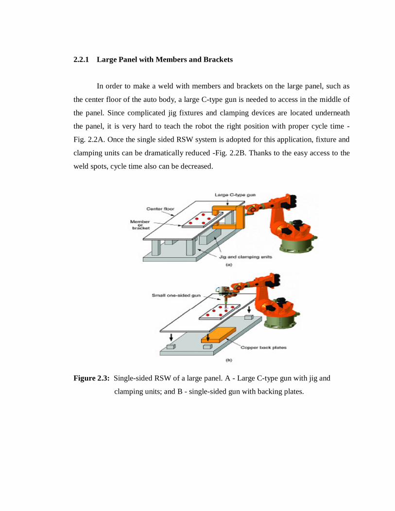
2.2.1 Large Panel with Members and Brackets
In order to make a weld with members and brackets on the large panel, such as
the center floor of the auto body, a large C-type gun is needed to access in the middle of
the panel. Since complicated jig fixtures and clamping devices are located underneath
the panel, it is very hard to teach the robot the right position with proper cycle time -
Fig. 2.2A. Once the single sided RSW system is adopted for this application, fixture and
clamping units can be dramatically reduced -Fig. 2.2B. Thanks to the easy access to the
weld spots, cycle time also can be decreased.
Figure 2.3: Single-sided RSW of a large panel. A - Large C-type gun with jig and
clamping units; and B - single-sided gun with backing plates.

2.2.2 Preassembled Parts
Usually, large parts are assembled at original equipment manufacturers (OEMs).
This means the OEMs need large facilities with complicated manufacturing processes.
Once parts are provided as a preassembled unit, lean assembly line manufacturing can
be achieved with a minimum number of production cells. As shown in Fig. 2.3, package
tray panels are assembled with three stages. In this case, the package tray side panel has
to be welded in the first stage and then the side outer panel is assembled, resulting in
body side complete. After that, this complete is built together with a package tray at a
later assembly station. However, if the package tray assembly is preassembled (Figure.
2.4), the manufacturing process can be reduced to two stages; body side complete stage
and its joining stage with package tray assembly. In order to assemble package tray
panels on the body side complete, a single-sided welding technique is needed. While arc
or laser beam welding may not be a perfect solution due to the gap issue of the end of
the panel edge, single- sided RSW has sufficient electrode force to control the gap.
(Dickinson, D. W., Franklin, J. E., and Stanya, A, 1980)

Figure 2.4: Conventional way to build package tray panels.
Figure 2.5: Proposed way to build preassembled package tray panels.

Spot weld quality is ensured through control of four principal parameters:
Current
Weld Force
Weld time
Electrode configuration
Automotive manufacturing system emphasized first on constant current in resistant
welding for its practical advantages:
Automatic compensation for power variation of mains.
Correction for welding gun impedance change when welding across large
sections of body panel.
Less program changes
Compensation allows different number of thickness to be welded on one setting
in many applications.
Weld timers provide the ability to monitor each spot weld so that its peak current
level is within predetermined limits. Dynamic resistance principle measuring the
variation of resistance over time during the weld is also used to ensure a higher level of
guaranteed quality. A sophisticated dynamic resistance system may incorporate an
adaptive control feature that varies the weld settings within certain limits to achieve
correct weld quality. The system also includes a weld current stepper function linked to
the counting of welds executed. The parameter limits are established for the specific
application and programmed for control. With capability of microprocessor based
controls, the constant current system could easily be attained for ensuring weld quality.
The weld time variation is unlikely with electronic controls. Welding forces is
applied pneumatically through line supply and hardly require a more rigid control
attained for ensuring weld quality. Tips of electrodes are to be maintained for consistent
current density. Either an individual weld count or an interface with the robot (if used) is
applied to make electrode dressing compulsory after an established number of cycles.

Pneumatic or electrically driven tip dressers shape both electrodes simultaneously to
ensure established geometry and decontaminated condition of the tip surfaces.
For quality of spot welding of automotive body, in addition to accurate panels and
jigs, tightly controlled position, sequence and direction of spot welding as well as
attitude of welding gun are necessary. Spot welding was basically manual operation.
Dedicated multi weld machines are used for high volume production in totally automatic
mode. The application of robots provided the appropriate human solution with much
higher precision in positioning and repeatability as shown Table 2.1.
With increased acceleration and deceleration of robots, spots can be applied at high
rate: a 50 mm step takes less than 0.3 seconds and a 300 mm one can be traversed in
under 0.7 second. Welding robots are generally supplied as a complete system including
gun transformer, air, water and electrical power supply, and all controls.
TABLE 2.1: Dimensional Accuracy in Body Assembly