Embed Size (px)
Citation preview
Bode 100 more than just a
PC controlled Vector Network Analyzer
It’s amazing what this compact measurement & test instrument can do for you!
Gain Phase Meter
Vector Network Analyzer
Impedance Meter
Sine Wave Generator
State of the art Vector Network Analyzer - unbeatable price performance ratio
PC controlled test set - much easier to work with
All test results already on the PC - simplifies documentation
Easy data processing - utilize software such as MATLAB®* or Excel®**
Compact and lightweight design - outstanding portability to test wherever you want
Standardized automation interface - simple integration into automated measurement setups
Standard file formats - effortless data sharing
Smart Measurement Solutions®
Bode 100 shown together with Future.Pad Mobile Tablet PC provided by www.ibd-aut.com
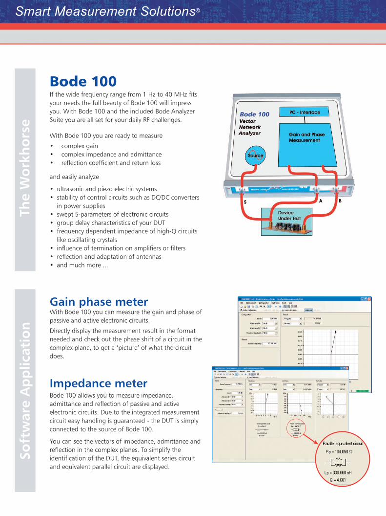
Bode 100 If the wide frequency range from 1 Hz to 40 MHz fits your needs the full beauty of Bode 100 will impress you. With Bode 100 and the included Bode Analyzer Suite you are all set for your daily RF challenges.
With Bode 100 you are ready to measure
complex gain•complex impedance and admittance•reflection coefficient and return loss•
and easily analyze
ultrasonic and piezo electric systems•stability of control circuits such as DC/DC converters •in power suppliesswept S-parameters of electronic circuits •group delay characteristics of your DUT •frequency dependent impedance of high-Q circuits •like oscillating crystals influence of termination on amplifiers or filters•reflection and adaptation of antennas•and much more ...•
Gain phase meter With Bode 100 you can measure the gain and phase of passive and active electronic circuits.
Directly display the measurement result in the format needed and check out the phase shift of a circuit in the complex plane, to get a ‘picture’ of what the circuit does.
Impedance meterBode 100 allows you to measure impedance, admittance and reflection of passive and active electronic circuits. Due to the integrated measurement circuit easy handling is guaranteed - the DUT is simply connected to the source of Bode 100.
You can see the vectors of impedance, admittance and reflection in the complex planes. To simplify the identification of the DUT, the equivalent series circuit and equivalent parallel circuit are displayed.
Soft
war
e A
pp
licat
ion
Th
e W
ork
ho
rse
Smart Measurement Solutions®
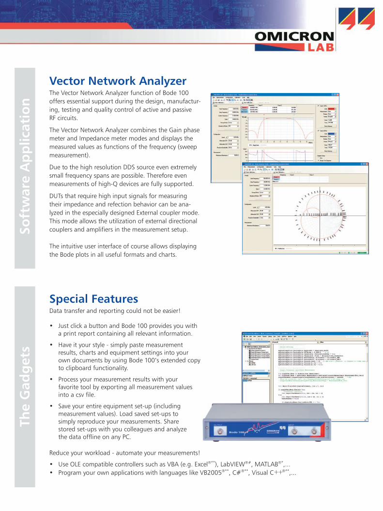
Vector Network AnalyzerThe Vector Network Analyzer function of Bode 100 offers essential support during the design, manufactur-ing, testing and quality control of active and passive RF circuits.
The Vector Network Analyzer combines the Gain phase meter and Impedance meter modes and displays the measured values as functions of the frequency (sweep measurement).
Due to the high resolution DDS source even extremely small frequency spans are possible. Therefore even measurements of high-Q devices are fully supported.
DUTs that require high input signals for measuring their impedance and refection behavior can be ana-lyzed in the especially designed External coupler mode. This mode allows the utilization of external directional couplers and amplifiers in the measurement setup.
The intuitive user interface of course allows displaying the Bode plots in all useful formats and charts.
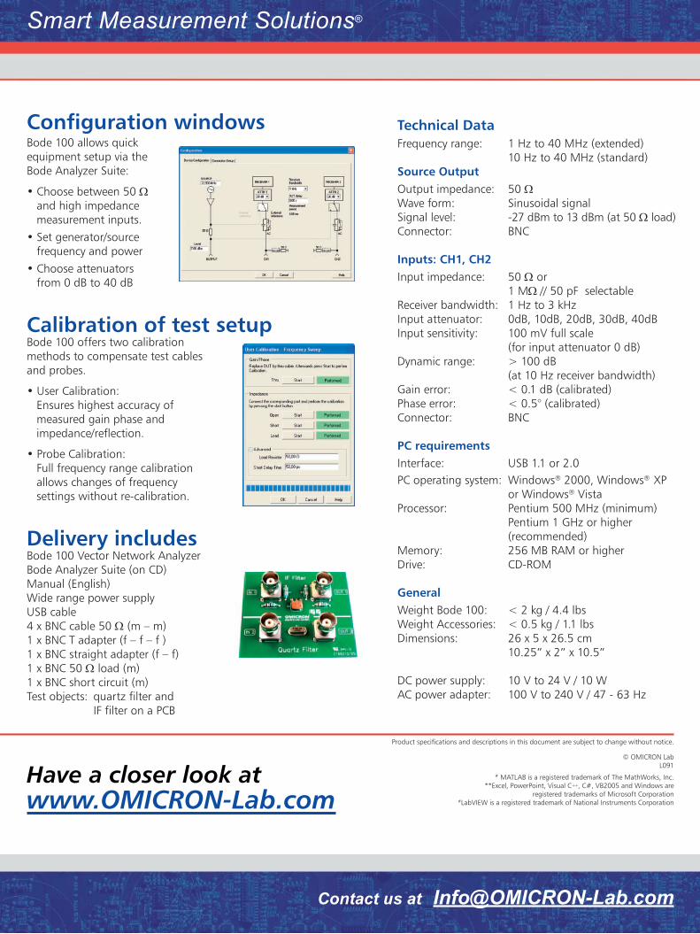
Special FeaturesData transfer and reporting could not be easier!
Just click a button and Bode 100 provides you with •a print report containing all relevant information.
Have it your style - simply paste measurement •results, charts and equipment settings into your own documents by using Bode 100’s extended copy to clipboard functionality.
Process your measurement results with your •favorite tool by exporting all measurement values into a csv file.
Save your entire equipment set-up (including •measurement values). Load saved set-ups to simply reproduce your measurements. Share stored set-ups with you colleagues and analyze the data offline on any PC.
So
ftw
are
Ap
plic
atio
nTh
e G
adg
ets
Reduce your workload - automate your measurements!
Use OLE compatible controllers such as VBA (e.g. Excel• ®**), LabVIEW®#, MATLAB®*,...Program your own applications with languages like VB2005• ®**, C#®**, Visual C++®**,...
Configuration windows Bode 100 allows quick equipment setup via the Bode Analyzer Suite:
Choose between 50 • Ω and high impedance measurement inputs.
Set generator/source • frequency and power
Choose attenuators • from 0 dB to 40 dB
Calibration of test setupBode 100 offers two calibration methods to compensate test cables and probes.
User Calibration: • Ensures highest accuracy of measured gain phase and impedance/reflection.
Probe Calibration: • Full frequency range calibration allows changes of frequency settings without re-calibration.
Delivery includesBode 100 Vector Network Analyzer Bode Analyzer Suite (on CD) Manual (English)Wide range power supplyUSB cable4 x BNC cable 50 Ω (m – m)1 x BNC T adapter (f – f – f )1 x BNC straight adapter (f – f) 1 x BNC 50 Ω load (m) 1 x BNC short circuit (m) Test objects: quartz filter and IF filter on a PCB
Technical DataFrequency range: 1 Hz to 40 MHz (extended)
10 Hz to 40 MHz (standard) Source OutputOutput impedance: 50 ΩWave form: Sinusoidal signalSignal level: -27 dBm to 13 dBm (at 50 Ω load)Connector: BNC
Inputs: CH1, CH2Input impedance: 50 Ω or 1 MΩ // 50 pF selectableReceiver bandwidth: 1 Hz to 3 kHzInput attenuator: 0dB, 10dB, 20dB, 30dB, 40dBInput sensitivity: 100 mV full scale
(for input attenuator 0 dB) Dynamic range: > 100 dB
(at 10 Hz receiver bandwidth)Gain error: < 0.1 dB (calibrated)Phase error: < 0.5° (calibrated)Connector: BNC
PC requirementsInterface: USB 1.1 or 2.0PC operating system: Windows® 2000, Windows® XP
or Windows® VistaProcessor: Pentium 500 MHz (minimum)
Pentium 1 GHz or higher (recommended)
Memory: 256 MB RAM or higher Drive: CD-ROM
GeneralWeight Bode 100: < 2 kg / 4.4 lbsWeight Accessories: < 0.5 kg / 1.1 lbsDimensions: 26 x 5 x 26.5 cm 10.25” x 2” x 10.5”
DC power supply: 10 V to 24 V / 10 WAC power adapter: 100 V to 240 V / 47 - 63 Hz
Product specifications and descriptions in this document are subject to change without notice.
© OMICRON Lab L091
Have a closer look atwww.OMICRON-Lab.com
Contact us at [email protected]
Smart Measurement Solutions®
* MATLAB is a registered trademark of The MathWorks, Inc. **Excel, PowerPoint, Visual C++, C#, VB2005 and Windows are
registered trademarks of Microsoft Corporation#LabVIEW is a registered trademark of National Instruments Corporation