Embed Size (px)
Citation preview
8/2/2019 BOC Laser Cutting Flyer
http://slidepdf.com/reader/full/boc-laser-cutting-flyer 1/2
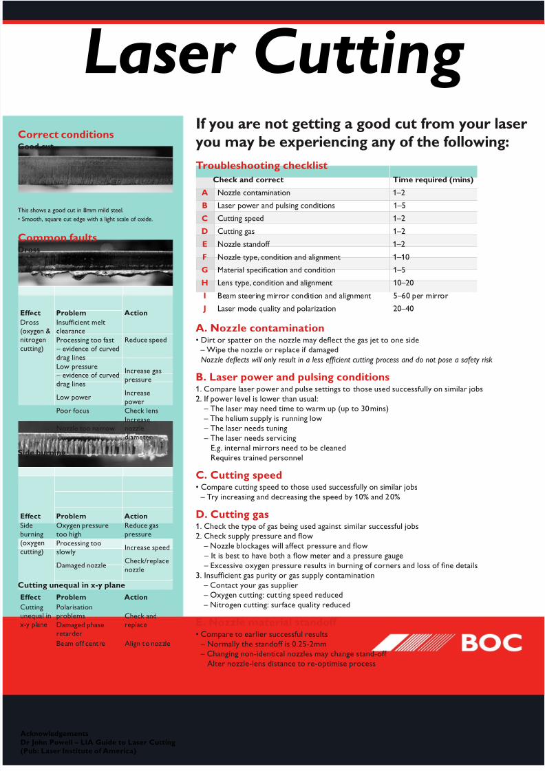
Troubleshooting checklist
Check and correct Time required (mins)
A Nozzle contamination 1–2
B Laser power and pulsing conditions 1–5
C Cutting speed 1–2
D Cutting gas 1–2
E Nozzle stando 1–2
F Nozzle type, condition and alignment 1–10
G Material specication and condition 1–5H Lens type, condition and alignment 10–20
I Beam steering mirror condition and alignment 5–60 per mirror
J Laser mode quality and polarization 20–40
A. Nozzle contamination• Dirt or spatter on the nozzle may defect the gas jet to one side – Wipe the nozzle or replace i damaged
Nozzle deects will only result in a less efcient cutting process and do not pose a saety risk
B. Laser power and pulsing conditions1. Compare laser power and pulse settings to those used successully on similar jobs
2. I power level is lower than usual:
– The laser may need time to warm up (up to 30mins) – The helium supply is running low
– The laser needs tuning
– The laser needs servicing
E.g. internal mirrors need to be cleaned
Requires trained personnel
C. Cutting speed• Compare cutting speed to those used successully on similar jobs
– Try increasing and decreasing the speed by 10% and 20%
D. Cutting gas1. Check the type o gas being used against similar successul jobs2. Check supply pressure and fow
– Nozzle blockages will aect pressure and fow
– It is best to have both a fow meter and a pressure gauge
– Excessive oxygen pressure results in burning o corners and loss o ne details
3. Insucient gas purity or gas supply contamination
– Contact your gas supplier – Oxygen cutting: cutting speed reduced
– Nitrogen cutting: surace quality reduced
E. Nozzle material stando • Compare to earlier successul results
– Normally the stando is 0.25-2mm – Changing non-identical nozzles may change stand-o
Alter nozzle-lens distance to re-optimise process
Laser Cutting If you are not getting a good cut from your laser
you may be experiencing any of the following:
AcknowledgementsDr John Powell – LIA Guide to Laser Cutting(Pub: Laser Institute o America)
Correct conditionsGood cut
This shows a good cut in 8mm mild steel.
• Smooth, square cut edge with a light scale o oxide.
Common aultsDross
Eect Problem Action
Dross(oxygen &
nitrogen
cutting)
Insucient meltclearance
Reduce speedProcessing too ast
– evidence o curved
drag lines
Low pressure – evidence o curved
drag lines
Increase gas
pressure
Low powerIncrease
power
Poor ocus Check lens
Nozzle too narrowIncreasenozzle
diameter
Side burning
Eect Problem Action
Side
burning
(oxygencutting)
Oxygen pressure
too high
Reduce gas
pressure
Processing tooslowly
Increase speed
Damaged nozzleCheck/replace
nozzle
Cutting unequal in x-y plane
Eect Problem Action
Cuttingunequal in
x-y plane
Polarisationproblems Check and
replaceDamaged phase
retarder
Beam o centre Align to nozzle

8/2/2019 BOC Laser Cutting Flyer
http://slidepdf.com/reader/full/boc-laser-cutting-flyer 2/2
IP XXXX FDAUS 0506 4K
Details given in this documen t are believed to be correct at the time of pr inting. Whilst proper care has been taken in the preparation, BOC Ltd excludes all and any liability permitted by law for injur y, damage or loss resulti ng from use. BOC is a trading name of BOC Limited, which is an operatingcompany within The BOC Group, the parent company of which is The BOC Group plc. The stripe symbol and the word BOC are a registered trademark of The BOC Group plc and used under licence by BOC Limited. © BOC Limited 2006. Reproduction without permission is strictly prohibited.
AUSTRALIA
131 262Fax: 132 427 • Email: [email protected]: www.boc.com.au
BOC Limited ABN 95 000 029 729
Riverside Corporate Park
10 Julius Avenue North Ryde, NSW 2113
AUSTRALIA
NEW ZEALAND
0800 111 333Fax: 0800 229 923 • Email: [email protected]: www.boc.co.nz
BOC Limited970–992 Great South Road
Penrose, Auckland
NEW ZEALAND
F. Nozzle type, condition and alignment
1. Is the nozzle o the right type (exit diameter) or the job?2. Is the nozzle worn or scratched?
3. Is the laser in the centre o the nozzle (i.e. centre o the gas jet)?
I not:
– The machine will not cut equally well in all directions: – Sparks may exit top o the cut zone when cutting in
certain directions
– Reduction o sparks leaving the bottom o the cut when
cutting in certain directions
G. Material specifcation and condition1. What is the material?
2. Is the condition o the material aecting the cutting?
– Surace coating (rust, paint, mill scale, etc.)
– Deep scratches
H. Lens type, condition and alignment1. Is the right ocal length lens being used? Is it tted correctly?2. Is the lens scratched or dirty? Both can give cutting problems
Even i it is clean it may have become over-heated
3. Is the laser beam correctly aligned onto the lens?
– Beam steering mirrors may need re-alignment
I. Beam steering mirror condition and alignment1. Are the mirrors clean?
– Take power readings ater each one. Power losses should be below 5% per mirror
2. Alignment should be square and central
– Realignment o mirrors requires training
J. Laser mode quality and polarisation1. The distribution o energy across the laser beam cross section is called its mode
– Poor mode quality results in poor cutting quality
– Laser mode identication and tuning require training
2. CO2 laser beam polarisation requires careul control or successul metal cutting
– I circular proles are oval on the bottom but circular on top, the polarising mirror(s)
may need cleaning or replacing
Gas consumption v. nozzle size
Laser Cutting Material related ault
Example o how material quality can aect cut quality
– oxygen cutting o low grade mild steel.
Nitrogen purity related aults
• Oxidation o the cut is evident at 100 ppm purity.
• The edge becomes rough at 0.1% purity (1000 ppm).
Laser mode quality andpolarisation
Perspex “mode burn”. Laser evaporation gives good 3Dapproximation o beam prole, but it requires practice
or reproducability, and produces noxious umes.
Good mode (TEM00)
Bad mode
Nitrogen,1% oxygen
100 ppmoxygen
0.1% oxygen
– cut edgeoxidised
25 ppmoxygen