Embed Size (px)
Citation preview
1
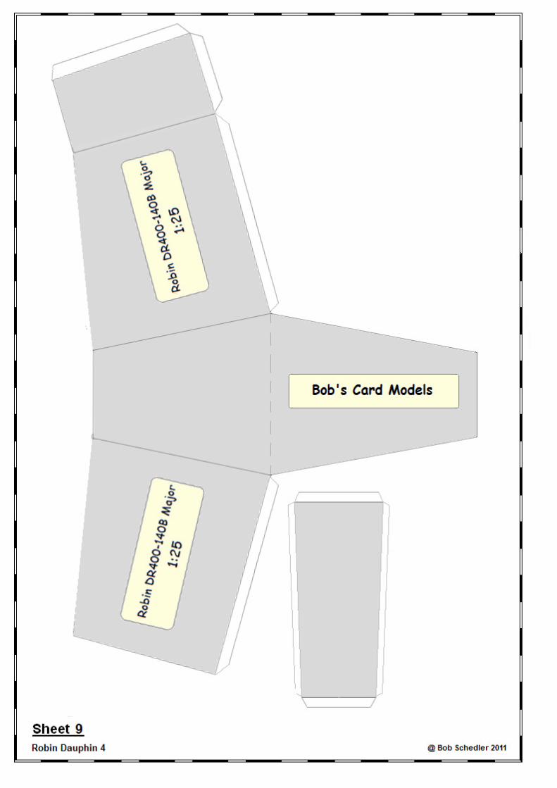
Bob's Card Models www.bobscardmodels.altervista.org and www.zealot.com [Resources]
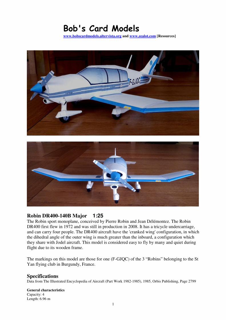
Robin DR400-140B Major 1:25
The Robin sport monoplane, conceived by Pierre Robin and Jean Délémontez. The Robin
DR400 first flew in 1972 and was still in production in 2008. It has a tricycle undercarriage,
and can carry four people. The DR400 aircraft have the 'cranked wing' configuration, in which
the dihedral angle of the outer wing is much greater than the inboard, a configuration which
they share with Jodel aircraft. This model is considered easy to fly by many and quiet during
flight due to its wooden frame.
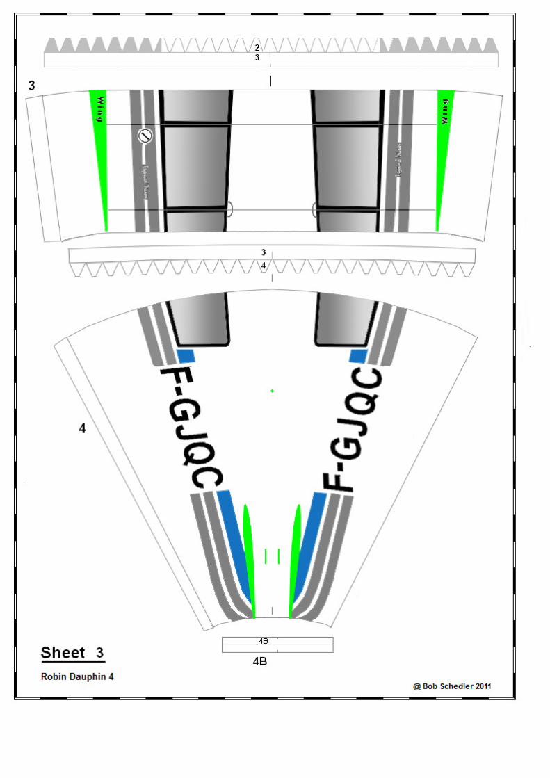
The markings on this model are those for one (F-GJQC) of the 3 “Robins” belonging to the St
Yan flying club in Burgundy, France.
Specifications
Data from The Illustrated Encyclopedia of Aircraft (Part Work 1982-1985), 1985, Orbis Publishing, Page 2799
General characteristics
Capacity: 4
Length: 6.96 m
2
Wingspan: 8.72 m
Height: 2.23 Wing area: 14.20 m² (152.85 ft²)
Empty weight: 600 kg
Gross weight: 1100
Powerplant: 1 × Lycoming O-360-A flat-four piston engine, 134 kW (180 hp)
Performance Maximum speed: 278 km/h
Range: 1450 km
Service ceiling: 4715 m
------------------------------------
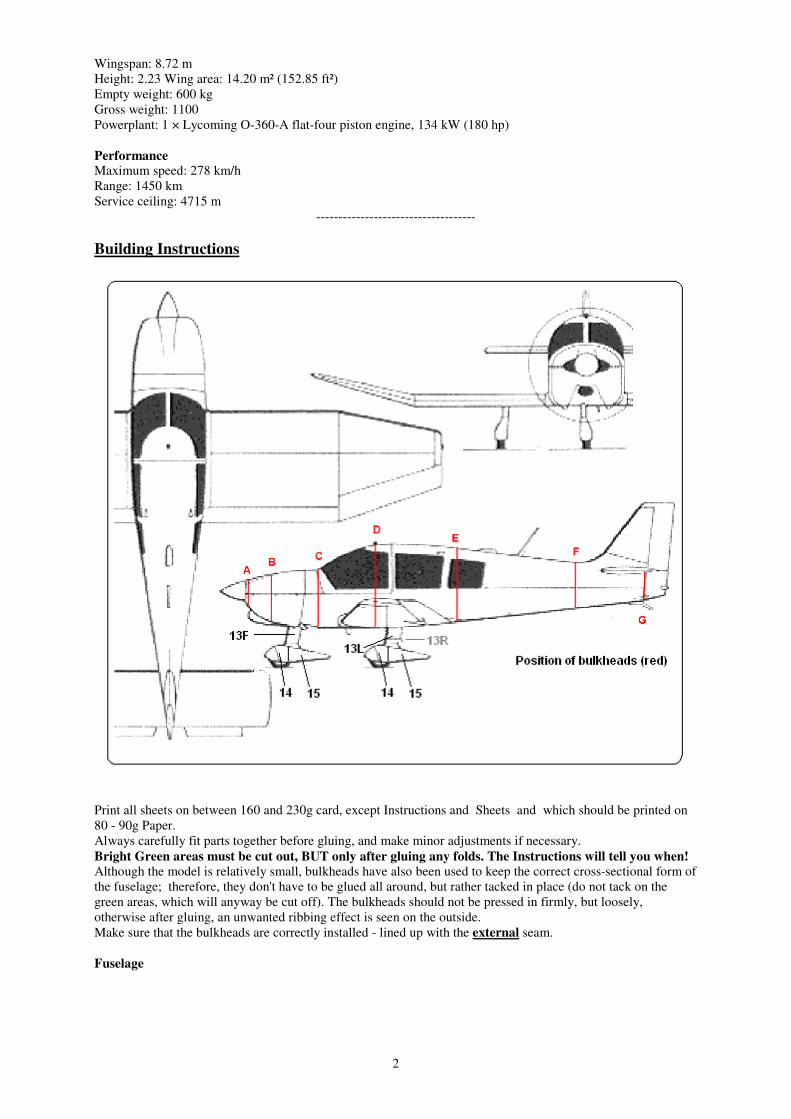
Building Instructions
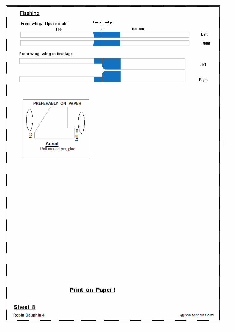
Print all sheets on between 160 and 230g card, except Instructions and Sheets and which should be printed on
80 - 90g Paper.
Always carefully fit parts together before gluing, and make minor adjustments if necessary.
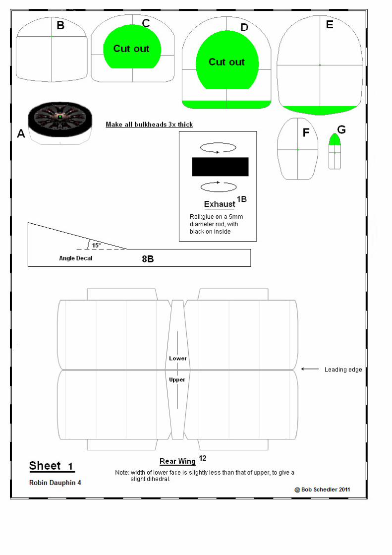
Bright Green areas must be cut out, BUT only after gluing any folds. The Instructions will tell you when!
Although the model is relatively small, bulkheads have also been used to keep the correct cross-sectional form of
the fuselage; therefore, they don't have to be glued all around, but rather tacked in place (do not tack on the
green areas, which will anyway be cut off). The bulkheads should not be pressed in firmly, but loosely,
otherwise after gluing, an unwanted ribbing effect is seen on the outside.
Make sure that the bulkheads are correctly installed - lined up with the external seam.
Fuselage

3
1. Cut out all bulkheads (BH), and make 3x thick, by gluing on waste card.
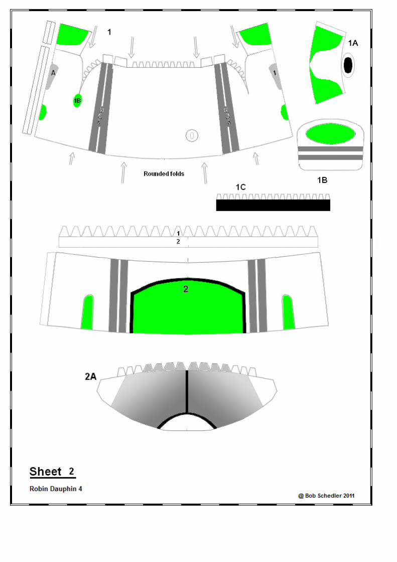
2. Cut out parts 1 to 4, round close and glue each of the tabs.
3. Glue tab strip 2-3 onto front of part 3, and tab strip 3-4 onto rear end of part 3.
2. In 4, glue BH F in place, then BH G in rear end of 4, and finally glue in tab 4B on rear.
3. In 3, insert and glue BH's E then D through the front end , and glue/tack in place. Glue 3 onto 4.
4. Glue 2A onto 3.
5. Cut out green area of part 2 (for cockpit, not for wing!), then glue 2 onto 2A/3.
6. Glue tab-strip 1-2 onto 2, then from rear, insert and glue/tack on BH C, after cutting out its green area.
7. Glue tab/strip 1-2 on 2.
8. Part 1: Insert BH A so that it is 'countersunk' about 0.5-2mm from the front, then insert/tack BH B. NB!
Before tacking BH B, insert a cocktail stick (= prop shaft) through holes in A and B to make sure that the
shaft is horizontal, before tacking/gluing.
9. Insert/glue 10g weight just behind bulkhead B, making sure that hole for front wheel shaft is kept free
(Glue: preferably epoxy, as wood glue will have difficulty in drying in enclosed space).
10. Part 1A (air intake, just below propeller): Cut out, round/glue to a truncated cone. Cut out green area, glue
on position marked on 1. Glue unit 1 onto part 2.
11. Insert exhaust 1B in position marked.
Main Wing
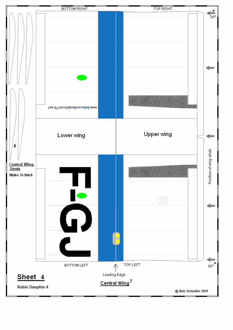
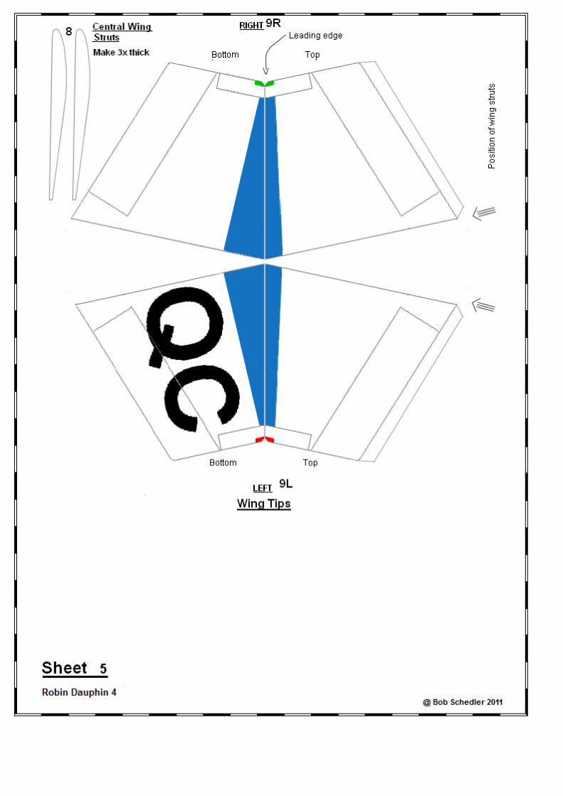
12. Cut out central part of main wing 7, fold along leading edge, and tab.
13. Cut out the 5 wing struts 8 (3x thickness), and glue in place on the bottom portion of the wing (NB: the two
outer struts, must be at 85° to the vertical, to take into account the bent wing tips - use the angle decal 8B).
14. Close/glue the wing.
Wing Tips
15. Cut out wing tips 9L, 9R and 2 struts 8. Assemble as for Main Wing.
16. Glue ONLY ONE of the tips to the end of the Main Wing. If the tip angles are correct, when the total wing
unit is laid on a flat surface, the wing tips should be about 2 cm above the surface.
17. Cut out green areas on fuselage parts 3 and 4, cut off green areas on BH's D and E (to make way for wing)
insert wing and glue in place (if necessary, enlarge the cut-outs). Then add the other wing tip.
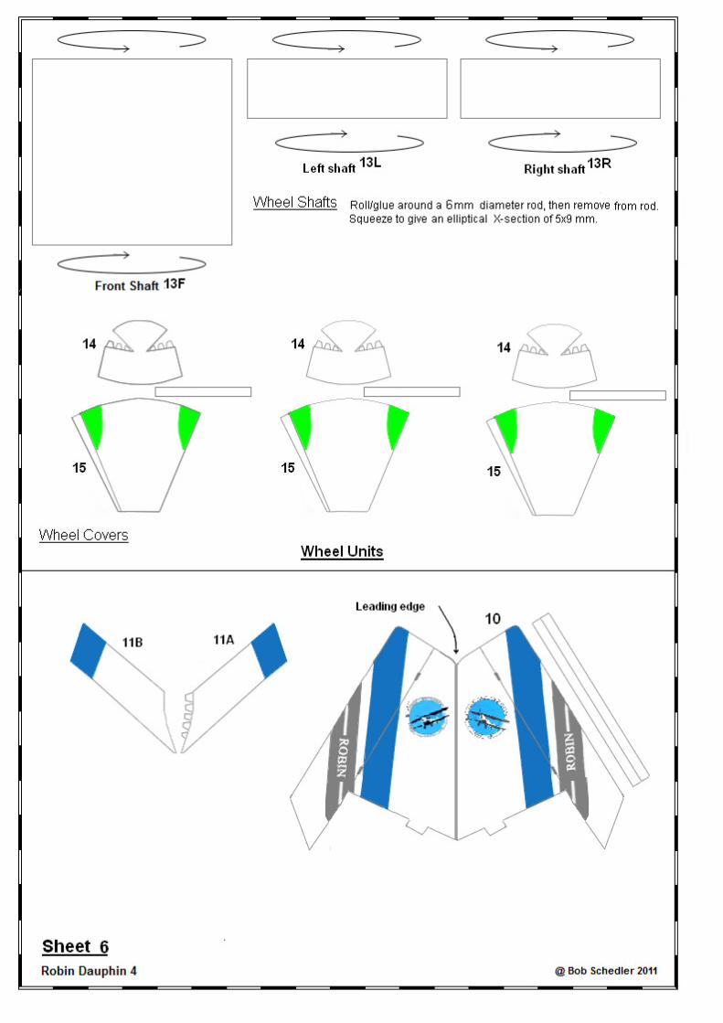
Tailplane
18. Cut out 12, close and glue. Cut out green portions and slits of 5.
19. Glue wing 12 in place, followed by fin 10.
20. Fold back tabs of 11A, and glue on 11B. Attach around base of Fin 10 where it joins wing 12.
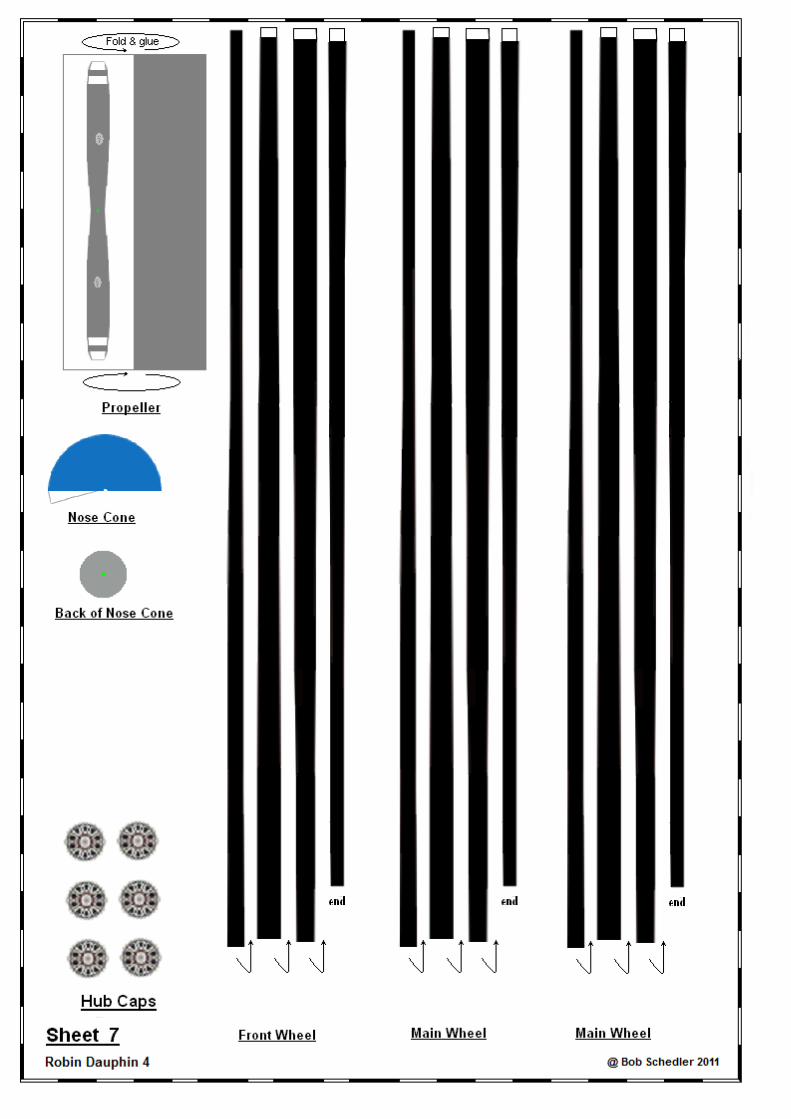
Undercarriage Cut out, and roll/glue the 3 wheels.
FRONT:
21. Assemble parts 14 and 15, glue on the shaft 13F, carefully noting the positions and angles in the diagram
above. The bottom of part 13F, using curved nails scissors, should be formed to make a perfect fit onto
14/15. Cut out the green area on part 1, insert the unit 13/14/15 as far as it will go with the correct angle off
90° (see diagram). Previously, the top of shaft 13F has had a drop of glue added, so that the whole shaft is
glued in 2 places - at the top, and where it exits the underside of the fuselage (part 1). Glue one of the
wheels inside the unit 14/15.
22. For the 2 main undercarriage units, likewise. Insert/glue in place under the wings after cutting out the 2
green areas for the undercarriage.