Embed Size (px)
Citation preview
I
I
@
I
INDEXPAGE
a
General Information ............................................................................................................... 2Warranty .... .. .. .. ... . . ... .. .. . ... .. . ... . .. ... . .. ... .. ... . .. ... .. . .. . . .... . .. ... . .. ... . .. ... . . ... .. .. . .. . .. .. .. . .. ... . .. .. .. .. . ........ 2Warranty Information ............................................................................................................. 3Warranty Procedure .............................................................................................................. 3
Purchaser’s Responsibility ...... . .. ... . .. .. . .. ... .. . ... .. . .. . .. ... . .. ... . .. .. .. .. ... . . ... .. .. . ... .. . ... . .. .. .. . .. ... . . .. .. 4Truck Preparation Information ............................................................................................... 4Truck Preparation Illustration ................................................................................................. 4Propane Tank Location/illustration ........................................................................................ 5Hard Water Area Map ............................................................................................................ 5
Machine Specifications ....... . .. ... . ... .. .. ... . .. ... .. .. .. .. ... . ... .. . .. ... . .. ... . .. .. .. .. ... . .. . .. . . .. .. .. .. .. .. . .. . .. . . .. .. 5Spare Parts Fiecommendation/Parts Orders .................................................................... 5-6
Water %1Chemical Flow Operation ..... . .. ... .. ... . .. ... . .. ... .. . ... . .. ... . .. ... . .. ... . .. .. .. . .. ... . .. .. .. . .. . ... . .. .. . 6Water Flow Diagram .............................................................................................................. 6Chemical Flow Diagram ......................................................................................................... 6
High Pressure Pump Information ......................................................................................... 7Bypass Valve Assembly Illustration ....................................................................................... 7High Pressure Pump/Chemical System Troubleshooting ............................................. 7&16Model 290 Cat Pump Operating Instructions .................................................................. 8-15Chemical Proportioning and Level Control Illustration ......................................................... 16Chemical Tank Troubleshooting .......................................................................................... 16
Heating System Information ............................................................................................... 16bleater Operating Instruction ................................................................................................ 17Heater Troubleshooting ....................................................................................................... 17
a Vacuum System Information .............................................................................................. 18Vacuum Flow Diagram ........................................................................................................ 18Vacuum Tank Filter Bag ...................................................................................................... 18Vacuum Blower Lubrication (Diagram) ................................................................................ 18Vacuum System Warranty ................................................................................................... 19Vacuum System Troubleshooting ........................................................................................ 20
Engine Manual/Warranty ............................................................................................. 21-28Engine Troubleshooting ....................................................................................................... 29
Electrical Diagram ............................................................................................................. 30Electrical Troubleshooting ................................................................................................... 30
Machine Installation Information ....................................................................................... 31Machine Tie Down Cleat Informationw ............$...................................................................... 31Propane Hook-Up Illustration ............................................................................................... 31Gas Hook-Up Illustration ...................................................................................................... 31Water Softener Information .................................................................................................. 32Jet Assembly ....................................................................................................................... 32Wand Assembly ................................................................................................................... 32Valve Assembly ................................................................................................................... 32
Machine Operation Instructions ......................................................................................... 33Control Panel ....................................................................................................................... 33Operation Precautions ......................................................................................................... 33Freeze Protection ...@............................................................................................................ 34
0
Cleaning and Chemical Precautions and Information ......................................................... 34Cleaning Stroke Procedure/Over-Wetting ........................................................................... 34
Maintenance Procedures ...... . ... . .. ... . .... . .. ... .. .. .. .. ... . .. ... . .. .. .. .. .. .. . .. ... . . .. ... . .. ... . .. . ... . .. . ... . .. . .. .. 35Overall Care of Machine .......$.............................................................................................. 35Maintenance Log ................................................................................................................. 36
—
GENERALINFORMATIONThis manual contains installation and operation instructions as wellas information required for proper maintenance, adjustment and re-pair of this Uink. Wrkcm the first and most important part of repair workis ttw cm’rect d[agnasis of the trouble, a general troubleshooting sec-tion and cm”ryxment manual troubleshooting charts have beert in-cluded far yaur oortvermiencxa
Unlike the garden tractor, Iavvnmower and cement mixer, all havingone or two functions to perform, the truck-mounted carpet cleaningplant has many functions to perform simultaneously.
@ Engine has to run crmsistent RPM.@ VWUUrn has to pull air and dirty water back from cleaning site.e Water pump provides stable pressure at proper water flow for
cleaning.@ Chemical has to be injected into the water stream at the right
consistency.@ Heater must maintain proper heat.a Vacuum tank must store dirty water until drained.
As you can see, it is not just a turn key operation with only one thingta worry about, Dcmmit start?!
In-E SYSTEMS WORK AsFOLLOWS:The water system takes incoming water at tap (low) pressure, com-bines it with chemical from the chemical system automatically,pumps it under high pressure through the heating system and out tothe chsaning toQ:l.After being sprayed into the carpet being cleaned,the wtMer/chwmical/soil solution is extracted by the vacuum systemand returned to th@waste recovery tank.
As there is no guess work in the manufacture of these highly ad-vanced cleaning plants, there must be none in preparing it to get thejob done in the field. It is the purpose of this manual to help you prop-erly understand, maintain and service your cleaning plant. Followthe directions carefully and you wil~be rewarded with years of profita-ble trauble-frwe operation.
It is imperativ~ that no section be overlooked when preparing forop-@ratienof this equipment.
The manufacturer uses this symbolthroughout the manual to warn ofpossible injury or death.
HYDRA= MASTER
Effective October 1, 19$31
WARRANTY IPOLNXf
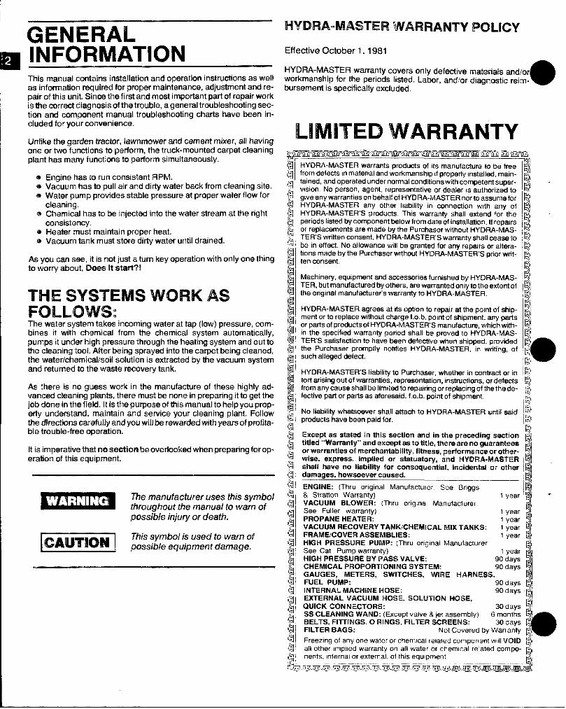
HYDRA-MASTER warranty covers only defective rnatawkalssmhrworkmanship for the periods listed. Labor, andfor diagnostic reim-abursement is specifically excluded.
LIMITED WARRANTYHYDRA-MASTER warrantsproductsof its manufactureto be freefrom defects in material and workmanship if properly rw.tailed, maint-ained, and operated under normal conditions with competent super-vwiion. No person, agent, representative or dealer is authorized togive any warranties on behalf o?HYDRA-MASTER nor to assume forHYDRA-MASTER any other liability m connection with any ofHYDRA-MASTER’S products. This warranty shall extend for tlmperiods listed by component below from date of installation. If repawsor replacements are made by the Purchaser without HYDflA-MAS-TER’S written consent, HYDRA-MASTER’S warranty shall cease tobe in effect. No allowance will be granted for any repairs or alttwa-tions made by the Purchaser without HYDRA-MASTER’S prior writ-ten consent.
Machinery, equipment and accessories furnished by l-fYf2FlA-MAS-TER, but manufactured by others, are warranted only to the extent ofthe original manufacturer’s warranty to HYDRA-MASTER.
HYDRA-MASTER agrees at its option to repair at the p@int of ship-ment or to replace without charge f .o. b. point of shipment, any partsor parts of products of HYDRA-MASTER’S manufacture, which with-in the specified warranty period shall be proved to PiYD RA-M.4S-TER’S satisfaction to have been defective when shipped, providedthe Purchaser promptly notifies HYDRA-MASTER, in writing, ofsuch alleged defect,
HYDRA-MASTER’S liability to Purchaser, whether in contract or intori arising out of warranties, representation, instructions, or d@fwXsfrom any cause shall be limited to repafring or replacing of the the r.$e-factive part or parts as aforesaid, f,o.b. point of shipment.
No liaMlity whatsoever shall attach to HYDRA-MASTER un~[ saidproducts have been paid for. 1$’Except as stated in this section and in the prwcedhtg aractlon
~~,
titled ‘Warranty” and except as to title, thare are no $wmrarmtwm
1
Ior warranties of mrarchantabiHty,fitness, prwformanoeor Wver- (wise, express, implied or statuatmy, and WW3RA-MASTER ~‘{shall have no liability for consequential, im%drmtalor othsr I ~damages, howsoever caused. ‘tENGINE: (Thru ongmal Manufacturer See 13nggs !? .& Stratton Warranty) 1 yearVACIJtJM BLOWER: (Thru original Manufacturer.See Fuller warranty) 1 yearPROPANE HEATER: 1year -,VACUUM RECOVERY TAMtWCkfEMICAL MIX TANKS: 1 year -}FRAME/Ct3VEFt ASSIEMB!JES: 1 year “jHIGH PRESSURE PtJMP: (Thru ongmal ManufacturerSee Cat Pump warranty) 1year F
HIGH PRESSURE BY PASS VALVE: 90 daysCHEMICAL PROPORTIONING SYSTEM:
~
90 days ““GAUGES, METERS, SWITCHES, WIRE HARNESS,FUEL PUMP: 90 days 1~,INTERNAL MACHINE HOSE:EXTERNAL VACUUM HOSE, SOLI,JTION HOSE, ‘odays ‘~$
QUICK CON NECTOf?S: 2.Odavs ,~?
SS CLEANING WAND: (Except valve& let assembly) 6 montk ~~BELTS, FITTINGS, O RINGS, FILTER SCREENS:
o
30 days i q’FILTER BAGS: Not Covered by Warranty ~~j
Freezing of any one water or chem!cal related component WIII VOID I@ —all other implied warranty on all water or chemical related comPo- E~
$iwi.m!iiiriii
nents. internal or external, of this equipmenty!
d/ ~ @;3.’,m.7’rL-m —7F.F%-m.titijrm.- -# .- .---, --’-.--’ -.-..--++- -+- 4..-.
WARRANTYINFORMATIONTo-avoid misunderstandings which might occur between machineowners and manufacturer, we are listing causes of component fail-ure that specifically voids warranty coverage. Such causes as listedbelow shall constitute abuse or neglect.
EN~fl~E: Operation at speed in excess of 2600 RPM. Failure tomaintain proper oil level (oil should be checked every 5 runninghours). Failure to use the proper oil viscosity and type (see enginemanual). Use of other than manufacturer’s recommended sparkplug in engines. Failure to perform recommended maintenance asdescribed on pages 3 and 4 of engine manual.
~~~~~~: Failure to lubricate impellers daily with LPS-1 orWD-40 lubricant. Failure to lubricate bearings as recommended inblower manual. Failure to maintain proper oil levels in the blower.Failure to use the correct oil grade and viscosity as recommended inblower manual. Failure to properly maintain blower safeguard sys-tems such as waste tank filter screen, vacuum safety relief valve invacuum tank lid and waste tank automatic shut-off system.
~1~1+ PRESSURE WATER PUMP: Operation of pump atpressures over 1200 PSI. Failure to maintain proper oil level as rec-ommended in pump manual. Failure to change oil in pump at recom-mended intervals. Failure to protect pump against freezing. Failureto maintain pump protection shut-off system. Failure to use watersoftener in hard water areas. Use of improper chemicals.
HEATER: Operation of heater without adequate water supply.Changing factory set propane regulator. Operating heater withoutproper ventilating. Failure to protect heater against freezing. Operat-ing machine at water pressures over 1000 PSI. Overfilling of pro-pane tank. Use of improper chemicals. Failure to use water softenerin hard water areas.
WACTANK: Failure to properly maintain filtering devices in tank.Failure to clean tank as recommended by manufacturer. Failure tomaintain vacuum safety release in tank lid. Use of improper chemi-cals.
~~~~. ~~~f%)~~~~~~~: Use of improper chemical. Failureto use water softener in hard water area. Operating machine withoutproper chemical filter screen. Failure to protect against freezing.
~ONTFlO~ PANEL: Failure to protect flow meter and waterpressure gauge against freezing.
VACUUM AND SOLUTION HOSES: Failure to protecthoses against freezing. Failure to protect hoses against burns fromenginelblower exhaust. Damage to hoses from being run over by ve-hicles. Kinking or cracking from failure to store or unroll hoses cor-rectly. Normal wear and tear from everyday use.
CLEANING WAND: Failure to protect against freezing. Obvi-ous physical abuse of wand.
WARRANTY PROCEDUREWarranty coverage is available to you ONLY through Hydra-MasterCorporation, 20309 64th Ave. West, Lynnwood, Washington 98036;When warranty parts are needed, write Hydra-Master WarrantyDept. at the above address, or call the Warranty/Service Dept. at(206) 775-7275. No collect calls will be accepted. Hours of theWarranty/Service Dept. are 8:00-11:30 am and 12:30-5:00 pm,Pacific Time.
IMPORTANT
parts shipment will be sent to the customer for the amount of theparts sent. The customer’s faulty parts must be returned forevalua-tion prior to the expiration of the thirty (30) day period. Upon warrantyapproval, a credit will be issued the customer for the replacementparts invoice. Werranty disapproval or faiiure to return the fauityparts withhr the thirty (30) day period allowed will result In the 9customer being charged for the replacement parts sent.
HOW TO ORDERTo obtain a proper diagnosis of your malfunction, and to order war-ranty replacement parts, it is important you foiiow the below proce-dure:
1. Call Hydra-Master Warranty/Service Dept. at (206) 775-7275
2. Give the Warranty/Service Representative the following informa-tion:
A.
:.D.E.F.G.H.
Name of your company and your address.Equipment Model (i.e. Hydra-Cat, Bobcat 2, etc.)Date of purchase.Hours on the unit.Seriai number of unit.Name of person authorized to order parts.Salesman unit purchased from.Description of malfunction.
i. Pressure readings on high pressure gauge with wand turned onand off.
3. ifwarranty replacement parts are needed, piease specify methodof shipment desired. NOTE: Ail replacement parts are sentfreight coiiect, via:
A. U.P.S.B. AirfreightC. Air mailD. Air expressE. Auto Freight
4. Do not give malfunctioning parts to a Hydra-Master Sales or Ser-vice Representative. All parts must be returned directiy to Hydra-Master, freight prepaid.
ONE FINAL NOTE:Any questions you have regarding the warranty program shouid bedirected to the Warranty/Service Dept. Personnel at Hydra-MasterCorporation.
We shall always endeavor to be fair in our evaluation of your war-ranty claim, and shall provide you with a compiete anaiysis of ourfindings.
Hydra-Master’s warranty poiicy provides replacement parts withoutcharge for thirty (30) days to customers maintaining current accountstatus. An invoice dated thirty (30) days from date of replacement
PURCHASER’S@3 ESPONSlBlLlTY
PF$MWITo AFWWtfAL OF WWT:@ install %+”extmicwplywood flooring in vehicle and cover with I
artificial turf.@ Have belly mounted pfioparretank installed on vehicle. Tank
must br3propane vapor type.
Purchase heavv dutv 42-60 amn hourbatte~ and have battery ‘slow’ ch&ge6 if new. If battery is notfully charged damage can occur to the engine chargingregulator.
AWHHW,AFJCE OF S&l[PMENT:@ If unit shows any outward signs of damage, do not sign the
delivery receipt until you have closely inspected the unit andnoted any damage on the delivery receipt. Have the freightcompany representative acknowledge the damage by signingthe notation of damage on the delivery receipt.
I%EADING (W CIPERATIION MANUAL:@ It is the purchaser’s responsibility to read the unit operation
manual and to familiarize himself with the information containedtherein.
SALES REPRESENTATIVERESPONSIBILITY
e The salesman from whom you purchased your unit isresponsible for supervising the correct installation of the unit inyour vehicle and thoroughly training you in its operation andmaintenance.
(X2RREGT INSTALLATION INCLUDES:Supewising the purchaser in the following:
@ Installation of through-floor fittings for propane and gasolinefuel lines: installing propane regulator included with unit, out-side vehicle; placing unit and recovery tank in vehicle andsecuring them with bolts or tie down cleats; connecting allpropane and gasoline lines; connecting battery; checkingpump, vacuum Mower and engine oil levels, prior to startingwrit; starting I-NMto check engine to see that all systemsfunction normally; also checking ali hoses, wands, etc., forcorrect operation.
TR%MNING SHALL INCLUDE:@ Thorough revi~w of the operation manual with purchaser;
instruction arndfamiliarization in: how to correctly start up andshut down unit; how to correctly clean with the unit; how, whereand how often to check and change component oil levels; howthe unit’s systems work; how to troubleshoot the unit; how todo basic repairs; safety precautions and their importance;freezing damage and how to avoid it and a thorough review ofthe unit warranty and warranty procedures.
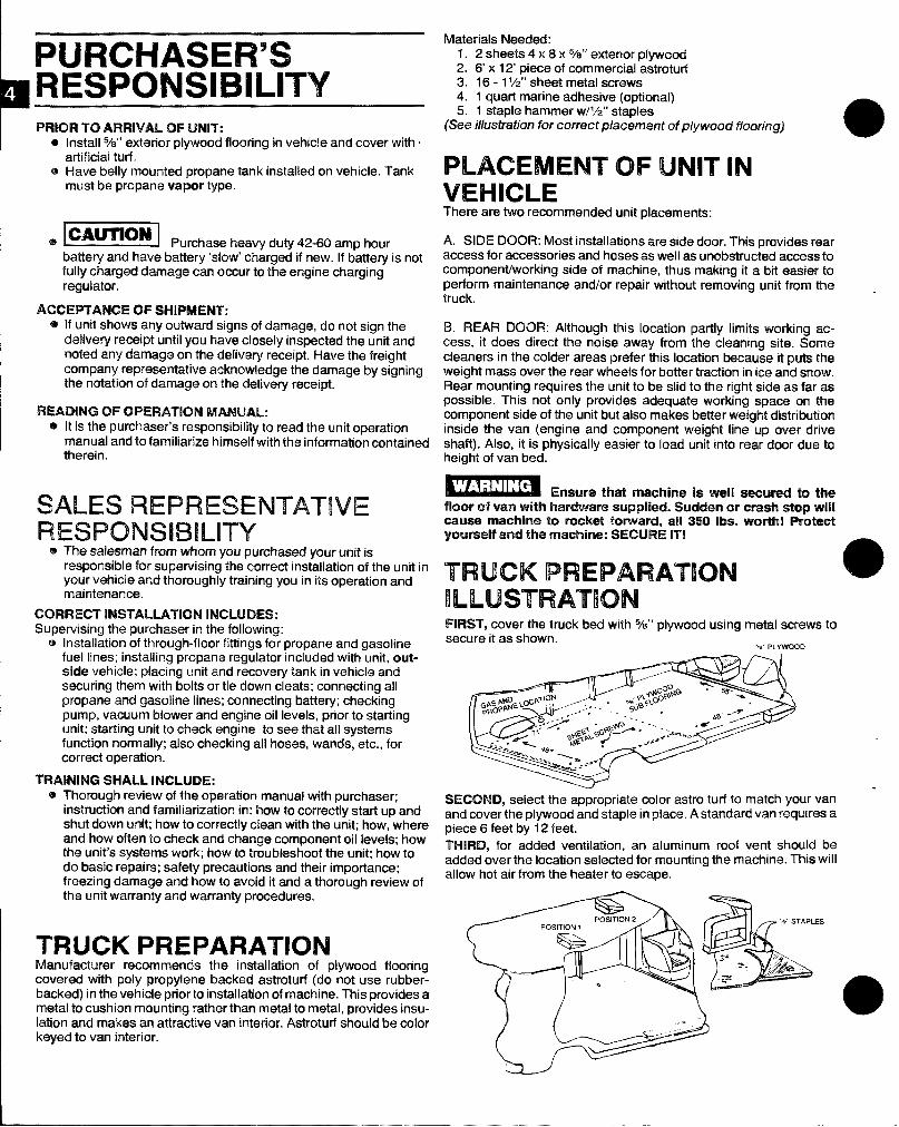
TRUCK PREPARATIONManufacturer recommends the installation of plywood flooringcovered with poly pnopylene backed astroturf (do not use rubber-backed) in the vehicle pricwtoinstallation of machine. This provides ametal to cushion mounting rather than metal to metal, provides insu-lation and makes an attractive van interior. Astroturf should be colorkeyed to van interior.
Materials Needed:1. 2 sheets 4 x 8 x 5/a” exterior plywood2. 6’ x 12’ piece of commercial astroturf3. 16-1 ‘/2” sheet metal screws4. 1 quart marine adhesive (optional)5. 1 staple hammer w/’/z” staples
(See illustration for correct placement of p!ywood ffooring)m
PLACEMENT OF UNIT’INVEHICLEThere are two recommended unit placements:
A. SIDE DOOR: Most installations are side door. This providw roaraccess for accessories and hoses as well as unobstructed access tocomponenffworking side of machine, thus making it a bit easier toperform maintenance and/or repair without removing unit from thetruck.
B. REAR DOOR: Although this location partly limits working ac-cess, it does direct the noise away from the cleaning site. Somecleaners in the colder areas prefer this location because it puts theweight mass over the rear wheels for better traction in ice and snow.Rear mounting requires the unit to be slid to the right side as far aspossible. This not only provides adequate working space on tlmcomponent side of the unit but also makes better weight distributioninside the van (engine and component weight line up over driveshaft). Also, it is physically easier to load unit into rem’ door due toheight of van bed.
Ensure that machino is !R@l secured to tl’mfloor of van with hardwar@ supplied. %Miran m’ crash atop willcause machine to rocket forward, all 350 lb. worth! Pratectyourself and the machine: SECURE IT!
TRUCK PREPARATION a
ILLUSTRATIONFIRST, cover the truck bed with 5/8” plywood using metal screws to
secure it as shown. % PLYWOOD
SECOND, select the appropriate color astro turf to match your vanand cover the plywood and staple in place. A standard van requires apiece 6 feet by 12 feet.THIRD, for added ventilation, an aluminum roof vmt should beadded over the location selected for mounting the machine. This willallow hot air from the heater to escape.
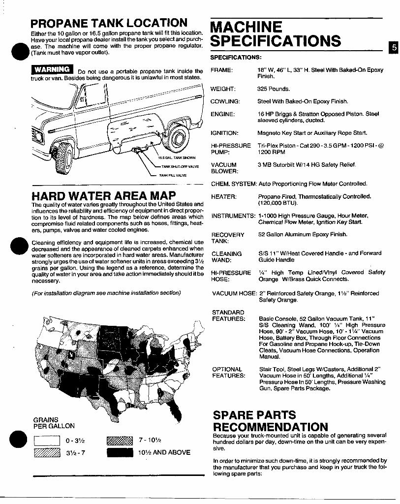
PROPANE TANK LOCATIONEither the 10 gallon or 16.5 gallon propane tank will fit this location.Have your local propane dealer install the tank you select and purch-
0
ase. The machine will come with the proper propane regulator.(Tank must have vapor outlet).
Do not use a portable propane tank inside thetruck or van. Besides being dangerous it is unlawful in most states.
-.. —
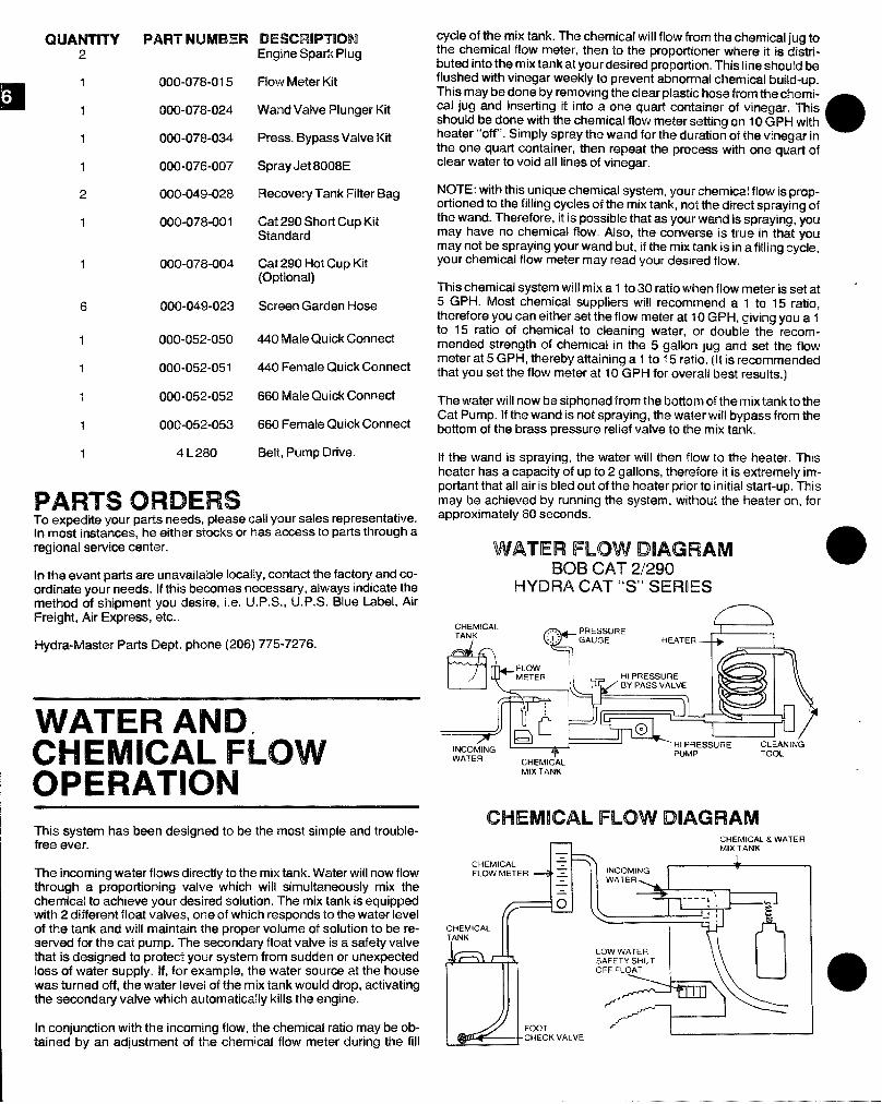
HARD WATER AREA MAPThe quality of water varies greatly throughout the United States andinfluences the reliability and efficiency of equipment in direct propor-tion to its level of hardness. The map below defines areas whichcompromise fluid related components such as hoses, fittings, heat-ers, pumps, valves and water cooled engines.
Cleaning efficiency and equipment life is increased, chemical usedecreased and the appearance of cleaned carpets enhanced whenwater softeners are incorporated in hard water areas. Manufacturerstrongly urges the use of water softener units in areas exceeding 3%grains per gallon. Using the legend as a reference, determine thequality of water in your area and take action immediately should it benecessary.
(For installation diagram see machine installation section)
—..PE-R--GALLON
,,.
u 0-31’2 E%E$%i37-’0”2Izzzn “/2-7 - ‘01’2ANDAB0vE
MACHINESPECIFICATIONS ESPECIFICATIONS:
FRAME: 18“ W, 46’ L, 33’ H. Steel With Baked-On EpoxyFinish.
WEIGHT: 325 Pounds.
COWLING: Steel With Baked-On Epoxy Finish.
ENGINE: 16 HP Briggs & Stratton Opposed Pk3crn. Steelsleeved cylinders, ducted.
IGNITION: Magneto Key Start or Auxiliary Rope Start
HI-PRESSURE Tri-Plex Piston - Cat 290- 3.5GPM -1200 PSI-@PUMP: 1200 RPM
VACUUM 3 MB Sutorbilt W/l 4 HG Safety Relief.BLOWER:
CHEM. SYSTEM: Auto Proportioning Flow Meter Controlled.
HEATER: Propane Fired, Thermostatically Controlled.(120,000 BTU).
INSTRUMENTS: 1-1000 High Pressure Gauge, Hour Meter,Chemical Flow Meter, Ignition Key Start.
RECOVERY 52 Gallon Aluminum Epoxy Finish.TANK:
CLEANING S1S 11” W/Heat Covered Handle - and ForwardWAND: Guide Handle
HI-PRESSURE ‘A” High Temp LinedlVinyl Covered SafetyHOSE: Orange W/Brass Quick Connects.
VACUUM HOSE: 2“ Reinforced Safety Orange, 1%“ ReinforcedSafety Orange.
STANDARDFEATURES: Basic Console, 52 Gallon Vacuum Tank, 11”
S/S Cleaning Wand, 100’ lA” High PressureHose, 90-2’ Vacuum Hose, 10’-1 l/.” VacuumHose, Batte~ Box, Through Floor ConnectionsFor Gasoline and Propane Hook-up, Tie-DownCleats, Vacuum Hose Connections, OperationManual.
OPTIONAL Stair Tool, Steel Legs W/Casters, Additional 2’FEATURES: Vacuum Hose in 50’ Lengths, Additional 1/4”
Pressure Hose In 50 Lengths, Pressure WashingGun, Spare Parts Package.
SPARE PARTSRECOMMENDATIONBecause your truck-mounted unit is capable of generating severalhundred dollars per day, down-time on the unit can be very expen-sive.
In order to minimize such down-time, it is strongly recommended bythe manufacturer that you purchase and keep in your truck the fol-lowing spare parts:
CWANTITY2
1
1
1
1
2
1
1
6
1
1
1
1
1
PAFIT NLMBER’i
000-0?8-015
000-07’$-024
000-078-034’
000-076-007’
000-049-028
000-078-001
000-078-004
000-049-023
000-052-050
000-052-051
MJO-052-052
000-052-053
4 L 280
PARTS ORDERS
DESGR!PT!OMEngine Spark Plug
Flow Meter Kit
Wand Valve Plunger Kit
Press. Bypass Valve Kit
Spray Jet 800BE
Recovery Tank Filter Bag
Cat 290 Short Cup KitStandard
Cat 290 Hot Cup Kit(Clpticmal)
Screen Gard@nHose
44o Male Quick Connect
440 Female Quick Connect
660 Male Quick Connect
660 Female Quick Connect
Belt, Pump Drive.
To expoditrayour parts newts, please call your sales representative.In most instances, he either stocks or has access to parts through aregional service center.
[n the event parts are unavailable locally, contact the factoy and co-ordinate your needs. If this becomes necessary, always indicate themethod of shipment you desire, i.e. U.P.S., U.P.S. Blue Label, AirFreight, Air Express, etc..
Hydra-fwfaster Parts Dept. phone (206) 775-7276.
WATER AMIDICHEMICAL FLOWOPERATIONIThis systam has been designed to be the most simple and trouble-frwe ever.
This incoming water flows directly to the mix tank. Water will now flowthrough a pmpcwtioning valve which will simultaneously mix thechemical to achiew your desired solution. The mix tank is equippedwith 2 different float valves, one of which responds to the water levelaf the tank and will maintain the proper volume of solution to be re-swwed for the cat pump. The secondary float valve is a safety valvethat is desigmsd to protect your system from sudden or unexpectedloss of water supply. if, for example, the water source at the housewas turned off, the water level of the mix tank would drop, activatingthe secondary valve which automatically kills the engine.
[n conjunction with the incoming flow, the chemical ratio maybe ob-tained by an adjustment crfthe chemical flow meter during the fill
cycle of the mix tank. The chemical will flow from the chwrrical jug tothe chemical flow meter, then to the proportuonerwhere it is cWatri-buted into the mix tank at your desired propo~lon. This line ~h~u~db~flushed with vinegar weekly to prevent abnormal chemical build-up.This may be done by removing the clear plastic hose from the c!wm+cal jug and inserting it into a one quart container of vinegar. Thisshould be done with the chemical flow meter sisttirq on 10 GPl+ withheater “off’. Simply spray the wand for the duration of the vinegar in a
the one quart cantainer, then repeat the process with one quart afclear water to void all lines of vinegar.
NOTE: with this unique chemical system, your chemical flow is pro-portionedto the filling cycles of the mix tank, not tha direct spraying afthe wand. Therefore, it is possible that as your wand is spraying, youmay have no chemical flow. Also, the converse is true in that youmay not be spraying your wand but, if the mix tank is in a filling cycle,your chemical flow meter may read your desired flow.
This chemical system will mix a 1 to 30 ratio when flow meter is set at “5 GPH. Most chemical suppliers will recommend a 1 to 15 ratio,therefore you can either set the flow meter at 10 GPH, giving you a 1to 15 ratio of chemical to cleaning water, or double the recomm-ended strength of chemical in the 5 gallon jug and set the flowmeter at 5 GPH, thereby attaining a 1 to 15 ratio. (It is recommendedthat you set the flow meter at 10 GPH for overall best results.)
The water will now be siphoned from the bottom of the mix tank to theCat Pump. If the wand is not spraying, the water will bypass from thebottom of the brass pressure relief valve tothe mix tank.
If the wand is spraying, the water will then flow to the heater. Thisheater has a capacity of up to 2 gallons, therefore it is extremely im-portant that all air is bled out of the heater prior to initial start-up. Thismay be achieved by running the system, without the beater on, forapproximately 60 seconds.
WATER FLOW DIAGRAMBOBCAT 2/290
WDRA CAT “S” SEFMES
CHEMICALTANK
~
PRESSURE
& ‘;:
GAUGE HEATER
+
MIXTANK
CHEMICAL FLOW DIAGRAMCHEMICAL& WI%TE17MIXTANK
vCHEMICAL v 7 &FLOWMETER d .= INCOMING
v WATER.
z{~ —
-IEMICALlNK
LOWWATERr - -K, SAFETYSHUT
OFF FLOAT
1
/-’--- tI .
As you remove your discharge manifold, there is a set of 3 check val-ves (which usually fall out during dis-assembly). If the surfaces ofthese check valves are dirty, or show signs of chemical build-up, it isprobable that they would remain open causing pressure loss or pul-sation. Upon inspecting the valves, make sure that the teflon buttonsin the valve spring retainers are still itact. Also examine the dis-charge manifold. Look for problems such as cracks, chemical build-up or warpage due to freezing. If this discharge manifold is warped, itwill cause the check valves to stick and will result in loss of pressure.
The Cat pump cups are often the source of pressure loss. Upon in-spection they may appear melted or torn, but often they will lookgood. Replace them anyway. There is no sure method of visually in-specting the cups. Hydra-Master recommends changing cupswhether they look good or not.
Anytime your’pump is being dismantled, Hydra-Master recommendsreplacement of all ‘o’ rings and seals. This is merely a convenienceto the customer to make sure that the Cat pump is in top operatingcondition.
The prrrm-a-lube seals located within the intake manifold will allowair to enter the pump if they are worn. Again, it is difficult to visuallypinpoint a defective prrrm-a-lube seal. Replace them all.
Within the piston sleeve cylinders there are 6 ‘o’ rings that are about
e
‘/4 the size of a penny. If these ‘o’ rings are bad, water will be pumpedback into the oil. If this has occured the oil will raise in level and willappear milky. If you are unable to repair seals right away, change oilfrequently. Repair the pump as soon as possible so as to not dam-age bearing or connecting rods.
Repairing of Cat pumps is not a difficult task. However, before disas-sembling make sure you have the proper parts required.
1- short (or hot) cup kit6- piston sleeve ‘o’ rings3- Prrrm-a-lube seals1- bottle Cat oil
Read instructions thoroughly, supplied in the Cat pump manual,prior to disassembly and follow directions as stated. Oil all sealsthoroughly prior to installation. (Remember, a newly scarred seal isno better than one you just took out.)
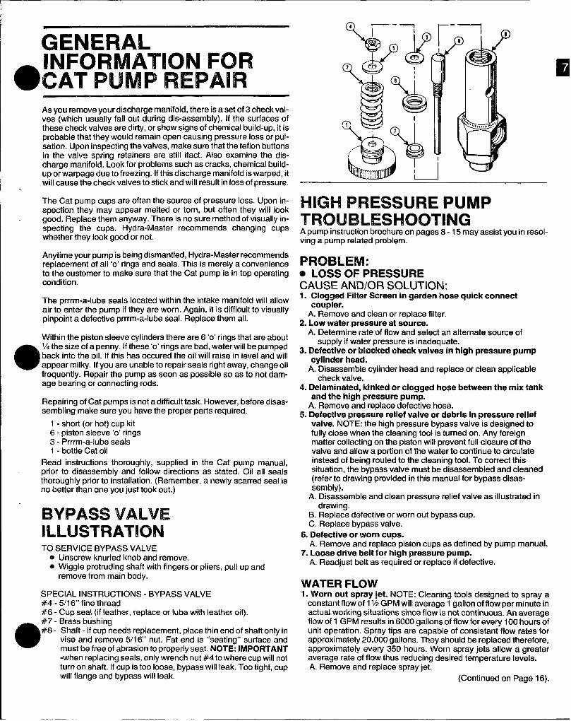
BYPASS VALVEILLUSTRATIONTO SERVICE BYPASS VALVE
@ Unscrew knurled knob and remove.@ Wiggle protruding shaft with fingers or pliers, pull up and
remove from main body.
SPECIAL INSTRUCTIONS - BYPASS VALVE#4 - 5/16“ fine thread#6 - CUD seal {if leather, redate or lube with leather oil).
a #7 - Brass bushing#8- Shaft - if cup needs replacement, place thin end of shaft only in
vise and remove 5/1 6“ nut. Fat end is “seating” surface andmust be free of abrasion to mo~erlv seat. NOTE: lMPORTANT-when replacing seals, only”wrenc~ nut #4to where cup will notturn on shaft. If cup is too loose, bypass will leak. Too tight, cupwill flange and bypass will leak.
HIGH PRESSURE PUMPTROUBLESHOOTINGA pump instruction brochure on pages 8-15 may assist you in resol-ving a pump related problem.
Plmmmvl:o LOSS OF PRESSURECAUSE AND/OR SOLUTION:1. Clogged Filter Screen in garden hose quick connect
coupler.A. Remove and clean or replace filter.
2. Low water pressure at source.A. Determine rate of flow and select an alternate source of
supply if water pressure is inadequate.3. Defective or blocked check valves in high pressure pump
cylinder head.A. Ok-assemble cylinder head and replace or clean applicable
check valve.4. Delaminated, kinked or clogged hose between the mix tank
and the high pressure pump.A. Remove and replace defective hose.
5. Defective pressure relief valve or debris in pressure reliefvalve. NOTE: the high pressure bypass valve is designed tofully close when the cleaning tool is turned on. Any foreignmatter collecting on the piston will prevent full closure of thevalve and allow a potilon of the water to continue to circulateinstead of being routed to the cleaning tool. To correct thissituation, the bypass valve must be disassembled and cleaned(refer to drawing provided in this manual for bypass disas-sembly).
A. Disassemble and clean pressure relief valve as illustrated indrawing.
B. Replace defective or worn out bypass cup.C. Replace bypass valve.
6. Defective or worn cups.A. Remove and replace piston cups as defined by pump manual.
7’. Loose drive belt for high pressure pump.A. Readjust belt as required or replace if defective.
WATER FLOW1. Worn out spray jet. NOTE: Cleaning tools designed to spray a
constant flow of 1‘/2 GPM will average 1 gallon of flow per minute inactual working situations since flow is not continuous. An averageflow of 1 GPM results in 6000 gallons of flow for every 100 hours ofunit operation. Spray tips are capable of consistent flow rates forapproximately 20,000 gallons. They should be replaced therefore,approximately every 350 hours. Worn spray jets allow a greateraverage rate of flow thus reducing desired temperature levels.A. Remove and replace spray jet.
(Continued on Page 16).
Model 290OPERATING INSTRUCTIONS
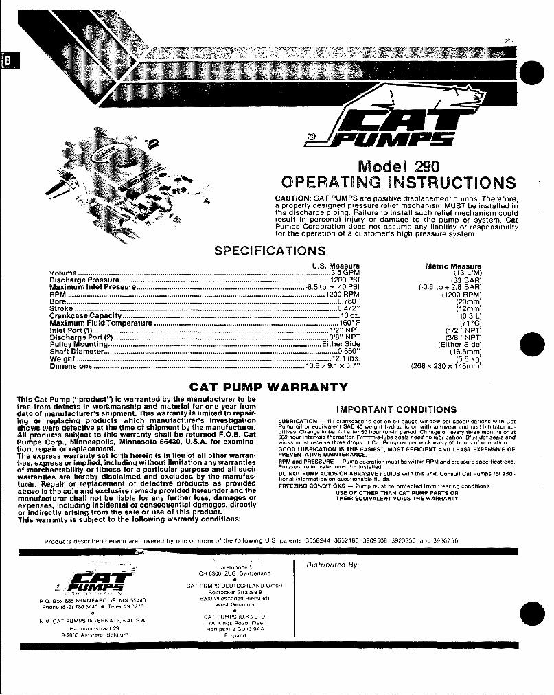
CAUTION: CAT PUMPS are positive displacement pumps. Therefore,a properly designed pressure reltef mechanism MUST’ be installed inthe discharge piping. Failure to install such relief mechanism couldresult in personal injury or damage to the pump or system. CatPumps Corporation does not assume arty liability or responsibilityfor the operation of a customer’s high pressure system.
SPECIFICATIONSU.S. Measuro
vdurrme ...........................................................................................................................3.5 Gf?MlMdmarfJcr Pressur@......................................................................................................1200 PSI#~m#num Ink$t Press ure . .... . .... .. . .... ... . .... ... . .... .... .... ... .. .... ... . ... ..... . .... .... . ... .... . .. -8.5 to + 40 PSI
............................................................................................................................. 1200 RPMB’occr... .. .... .. . .... .. . .... .. . .... .. . ..... .. . ... .... .. .... .. . .... ... . .... ... . .... ... .. ... ... .. .... ... .. ... .... .. ... ..... .... ............O.78O''Stroke . .... ... .... .. . ... ... ..... .. . .... ... . .... ... . ..... .. . .... ... . .... ... . .... ... .. ... ... . ..... ... .. ... .... . .... ... .. .... .... ........O.472''Crankcase Capacity ..........................................................................................................10 oz.Maximum Fluid Tmpmtlm ..........................................................................................1k30”FInlet Port (l) .. . ... .. . .... .. .. ... ... .. ..." . . ..... .. . .... .... . ... ... .. ... ... . ..... ... . .... ... .. ... .... . .... ... . ..... ... .. .... ... 1/2” N PTLNschargaPcwt(2) ..... ........................................ .......................................... ..................3/8'' N PTI%dky MQunting .... .. . .... ... . .... ... . .... ... . .... ... . .... ... . .... ... . .... .... . ... ... .. .... ... .. .... ... . .... ... .. .... .. Eit her SideShaft fJimmrt@r ..................................................................................................................O.65O''Wtright ............................................................................................................................ 12.1 tbs.Dim@n$iQn$.......................................................................................................10.6 X 9.1 X 5.7”
CAT IPUMPThis Cat Pump ($’prackt”) is warranted by the manufacturer to beMoe from dttrf~cts in workmanship and matr3rial for one year fromdat@of rmmufactumr’s sh@’rmwTl. This warranty is I!mifed to repair-ing or ropltmhr~ products which manufacturer’s investigationMrcmrawara ddmtiv~ at the time of shipment by the manufacture.AIUproducts sub@ to this warranty shall be retumad F.0.k%Cat
/Pumps Corp., M mmnwpdis, Mhmeaota 55430, tJ.S.A. for axamina.tkm,impairor raplacament.Tim express warranty set fcwthhwwin is IFIlhw of all other warren.tkm, exprcmsor hrmplid,hclmfhg without limitation any warrantiesd merdrmatrahility or fitness for a particular purpose and all suchwwrarotle%+are Iwwekwdisclaitmatf and exc!uded by the mamdac-turm’. Repsrtr cm I’E@WMIWtnt Qf defectiw products as providedabwm la the501@ 8rIud exclusive remmty providad hereunder and thammnufactumr shall mrt be liable for any further loss, dama ea or
7tmfmnwwi, irmc!udim’u$Incktwrtal m consequential damages, d rectlyor irrdlrectly arisiq Irm the sale m trae o~ this product.Thla warranty it?aub@ct tothe following warranty condition
WARRANTY
Metric Measure[13 L./M)
(-0.6 to+ !2!8: :;;;(1200 RPM)
(20mm)(12mm)
(0.3 L)(71“c)
(1/2” NPT)(3/8” NPT)
(Either Side)(l~5\mk~]
(268 x 230x 146mm)
IMPORTANT t2C)NKNTlCJNSLUaFIICATION - fill crankcase to dot on o(I gauge window per specifications with CatPump 011 or equivalent SAE 40 weight hydraulic 011 with antlwear and rust Inhibitor ad.dttives. Change mltml fill after 50 hour run.m parmd, Chwage O(I %V%Wibrme months or atS00 hour lflterWdS thereafter. Prrrrrm.a-lube seals need no Iubrlcatton. Blu% dot WX3113andwicks mu$t r9C91v9 three drops of Cat Pump 011 per wick every 54 hour8 of operation.
GOOD LUBRICATION IS WE EASIEST, MOST EFFfC!ENT AND LEAST EXPW4SWE OFPREVENTATIVE MAINTENANCE.IIPMmd PRESSURE- Pump oper@#o” must be wlthm RPM and pmasure specttlcat(onsPressure relkef valve must be [nstalled,
DO NOT PUMP ACIDS OR AL!RASIVE FUJIOS wdh this unit Consult Cat Pumps km addl.tlonal #nf0rr17at10n on questionable flulds.
FREEZING CONDITIONS - Pump must be protectect 1rom iroez!ng cond!l Ions.USE OF OTHER THAN CAT PUMP PARTS Or?THEIR EQUIVALENT VOIOS THE WAWIAMIT
Products df3$Cr(b@dhereon are covered by one or more of the follo’w,og U S Patems 3558244 3652188 3809508 3920356 and 3930 T56
~Hq&g&”,.
LorelohOhe 5CH 6300. ZUG Switzerland
eCAT PUMPS DEUTSCHLANO GmbH
,,!,f+,.,~f{.., ,,, > Restocker Strasse 9
P O BOX 885 MW4NEAPOLK. MN 55440Phone (612) 7805440 m Telex 290276
6200 Wlesbaden.Blersladlwest Germany
e.N V CAT PUMPS INTERNATIONAL SA
CAT PUMPS (U K ) LTO17A K,ngs RoaIY Fleet
Harmonteslraal 29 Hampsh, re GU13 9AA0.2000 Antwerp Belwum England
3/8’
1 \
1/2”-’ II
I
1.34[34]4 ! L- ~apI
.79k(20)
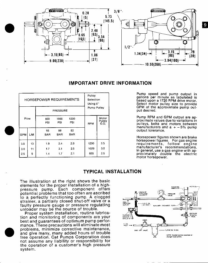
IMPORTANT DRIVE INFORMATION
Pulley
HORSEPOWER REQUIREMENTS SelectionUsing 5“Pump Pulley
PRESSURE
Flow 800 1000 1200 tblotorPsl Psl Psl P; I&y
RPM .
55 69 83;PM LIM BAR BAR BAR
3.5 13 1.9 2.4 2.9 1200 3.5
3.0 11 1.7 2.1 2.5 1029 3.0
2.5 9 1.4 1.7 2.1 858 2,5
Pump speed and pump output ingallons per minute as tabulated isbased upon a 1725 RPM drive motor.Select motor pulley size to provideGPfvl of the approximate pump out-put desired.
Pump RPM and GPM output are ap-proximate values due to variations inpulleys, belts and motors betweenmanufacturers and a + – 5°/0 pumpoutput tolerance.
Horsepower figures shown are brakehorsepower figures. For gas enginerequirements, follow enginemanufacturer’s recommendations.In general, use a gas engine with ap-proximately double the electricmotor horsepower.
TYPICAL INSTALLATION
The illustration at the right shows the basicelements for the proper installation of a high--pressure pump. Each component offerspotential problems that too often are ascribedto a perfectly functioning pump. A cloggedstrainer, a partially closed shut-off valve or afaulty pressure gauge or pressure regulatingunloader may be the source of trouble.
Proper system installation, routine lubrica-tion and monitoring of components are yourbest and guarantees of optimum pump perfor-mance. These precautions will eliminate most
a
problems, minimize corrective maintenance,and give many, many added hours of troublefree operation. Cat Pumps Corporation doesnot assume any liability or responsibility forthe operation of a customer’s high pressuresystem.
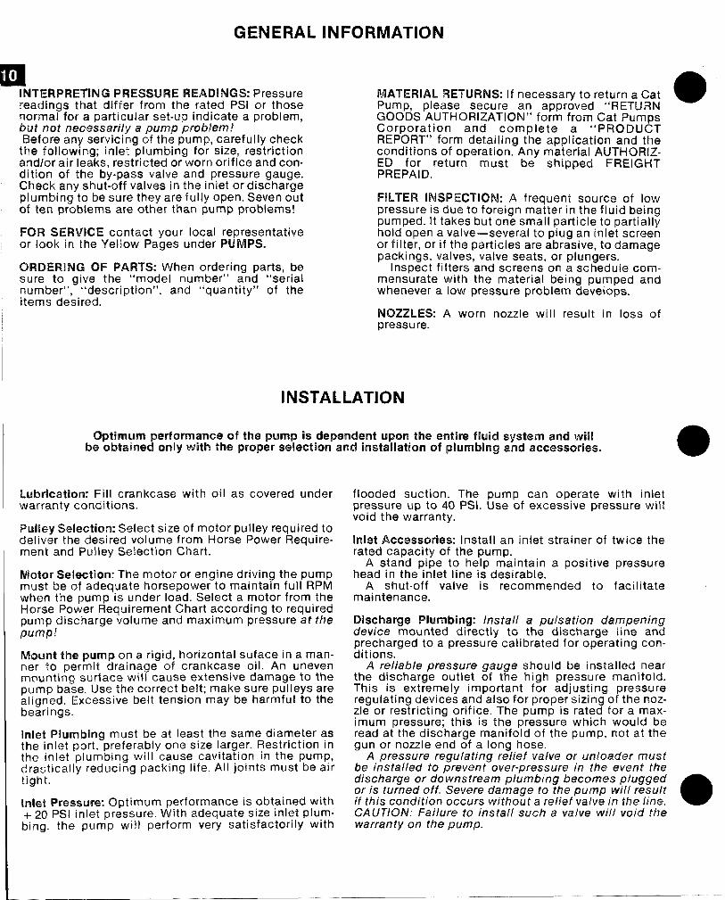
GENERAL IINFORMATIC)N
p~It
INTERPRETING PRESSURE READINGS: Pressure MATERIAL RETURNS: If necessary to return a Cat areadings that differ from the rated IISl or those Pump, please secure an approved “RETLfRNnormal far a particular set-up indicate a problem, GOODS AUTHORIZATION” form from Cat Purnrmbuf not necessarily a pump probkem!Ehefore any servicing of the pump, carefully check
the following; inlet plumbing for size, restrictionandlor air leaks, restricted or worn orifice and con-dition of the by-pass valve and pressure gauge.Ch@ck any shut-off valves in the inlet or dischargeplumbing to be sure they are fully open. Seven outof ten problems are other than pump problems!
FOR SERVICE contact your local representativecw look in the Yellow Pages under PUMPS.
ORDERING OF PARTS: When ordering parts, besure to give the “model number” and “serialnumber”, “description”, and “quantity” of theitems desired.
Corporation and complete a “PRODUCTREPORT” form detailing the application and th~conditions of operation. Any material AIJTHQRIZ-ED for return must be shipped FREIGHTPREPAID.
FILTER INSPECTION: A frequent source of lowpressure is due to foreign matter in the fluid beingpumped. It takes but one small particle to partiallyhold open a valve— several to plug an inlet screenor filter, or if the particles are abrasive, to damagepackings, valves, valve seats, or plungers.
Inspect filters and screens on a schedule comm-ensurate with the material being pumped andwhenever a low pressure problem develops.
NOZZLES: A worn nozzle will result in loss ofpressure.
INSTALLATION
Optimum ptwfomantm at tfw pump is dependent upon ths entire fluid system and willbe obtained only with NM?properselection and installation of plumb!ngand acmassories. @
Lubrication: Fill crankcase with oil as covered underwarranty conditions.
PIuil@y $elactitm: Select size of motor pulley required todeliver the desired volume from Horse Power Require-ment and Pulley Selection Chart.
Wutar Sel@cticm: The motor or engine driving the pumpmust be of adequate horsepower to maintain full RPMwhen the pump is under load. Select a motor from theHorse Power Requirement Chart according to requiredpIJrYIP discharge volume and maximum pressure at tfrepump!
MourIt tl’m pump cm a rigid, horizontal suface in a man-ner to permit drainage of crankcase oil. An unevenmounting surface will cause extensive damage to thepump base. Use the correct belt; make sure pulleys arealigned. Excessive belt tension may be harmful to thebearings.
Inlat Plumbing must be at least the same diameter asthe inlet port, preferably one size larger. Restriction inthe inlet plumbing will cause cavitation in the pump,di”autically reducing packing life. All joints must be airtight.
Inhat Prmwwm%x Optimum performance is obtained with+ 20 PSI inlet. pressure. With adequate size inlet plum-bing, the pump will perform very satisfactorily with
flooded suction. The pump can operate with inletpressure up to 40 PSI. Use of excessive pressure willvoid the warranty.
Inlet Accessories: Install an inlet strainer of twice therated capacity of the pump.
A stand pipe to help maintain a positive pressurehead in the inlet line is desirable.
A shut-off valve is recommended to facilitatemaintenance.
Discharge Plumbing: Install a puisatian dampeningdevice mounted directly to the discharge line andprecharged to a pressure calibrated for operating con-ditions.
A re/iab/e pressure gauge should be installed nearthe discharge outlet of the high pressure manifold.This is extremely important for adjusting pressureregulating devices and also for proper sizing of the noz-zle or restricting orifice. The pump is rated for a max-imum pressure; this is the pressure which would beread at the discharge manifold of the pump, not at thegun or nozzle end of a long hose.
A pressure regulating relief valve or unloader mustbe installed to prevent over-pressure in the event thedischarge or downstream plumbing becomes pluggedor is turned off. Severe damage to the pump wif[ resultif this condition occurs without a rslief valve in the line. aCA UTIOIV: Failure to install such a valve wtil void thewarranty on the pump.
I58
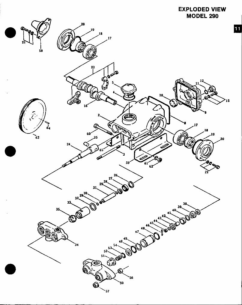
EXPLODED VIEWMODEL 290
20
17
’15
—
‘ 57
❑
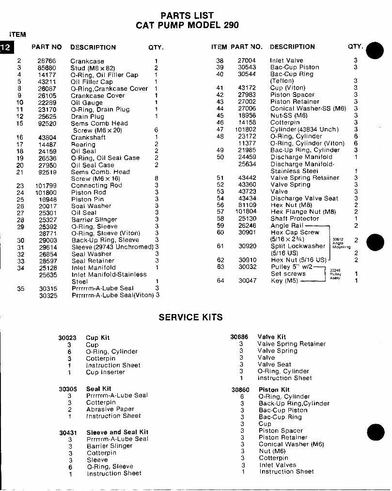
PARTS LIST
ITEM
23458910111215
161718192’021
23242526
X2!2
3’031323334
35
PART No
28766856W)141774321126(M3726105222892317025625%2520
438041448724159265362795092519
101799101 ‘Boo
169482001725301253272539228771290032961426854285972512825635
3031530325
CAT PUMP MODEL 290
Dmclllm’lc)l’i! QTY. ITEM PART NO.
CrankcaseStud (M8 x 82)Cl-Ring, Oil Filler CapOil Filler CapO-Ring, Crarrkcase CoverCrankcase CoverOil GaugeO-Ring, Drain PlugDrain PlugSems Comb l-leadScrew (IM6 x 20)
CrankshaftRearingOil SealQ. Ring, Oil Seal CaseOil Seal CaseSemrs Comb. HeadScrew (M6 x 16)Confecting RodPiston RodPiston PinSeal WasherOil Sea!Harrier SlingerO-Ring, SleeveO-Rina, Sleeve (Viton)
;1111111
612222
8333333333
3a3940
414243444546474a
4950
515253545657585960
Back-U”p Ring, SleeveSleeve (29743 Lfnchrorned) 3 61Seal Washer 3Seal Retainer 3 62Inlet Manifold 1 63Inlet Manifold-StainlessSteel 64Prrrrrm-A-Lube Seal :Prrrrrm-A-Lube Seal(Viton) 3
3002336311
3’03053321
30431333
i1
SERVICE KITS
Cup KitcupO-Ring, CylinderCotterpinInstruction SheetCup Inserter
Seal KitPrrrrrm-A-Lube SealCotterpinAbrasive PaperInstruction Sheet
Slt?eve and Seal KitPrrrrrm-A-Lube SealBarrier SlingerCotterpinSleeveO-Ring, Sleeveinstruction Shee’
270043054330544
431722798327002270061895614158
1018022317211377219852445925634
4344243360437234343481109
101804251302624630901
30920
3091030032
30047
30686333331
3086063
:33333331
DESCFUPTIC)N
Inlet Valvef3ac-Cup PistonBat-Cup Ring(Teflon)Cup (Viton}Piston SpacerPiston RetairwConical Washer-SS (M6)Nut-SS (M6)CotterpinCylinder (43834 Unch)O-Ring, CylinderO-Ring, Cylinder (Viton]Bat-Up Ring, CylinderDischarge ManifoldDischarge Manifold-Stainless SteelValve Spring RetainerValve SpringValveDischarge Valve SeatHex Nut (MS)Hex Flange Nut (M8)Shaft ProtectorAngle Rail
1Hex Cao Screw
3
3333’33336631
;33322
;
(5/16 x23A) 30612 2Split Lockwasher Mk,ng
a(5116 US) 2I’-lex Nu~ (5/16 LfS)~ 2Pulley 5“ w{2
JSet screws
30246Pulley 1
Key (M5)Asbly
1
Vahm KitValve Spring RetainerValve SpringValveValve SeatO-Ring, CylinderInstruction Sheet
Piston KitO-Ring, CylinderBack-Up Ring, CylinderBat-Cup Pistoni3ac-Cup RingcupPiston SpacerPiston Retain@rConical Washer (M6)Nut (!v16)CotterpinInlet ValvesInstruction Shr3e!
e%
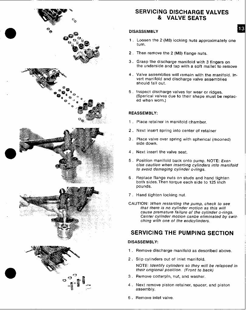
SERVICING DISCHARGE VALVES& VALVE SEATS
DISASSEMBLY
1.
2.
3.
4.
5.
Loosen the 2 (M8) locking nuts approximately oneturn.
Then remove the 2 (M8) flange nuts.
Grasp the discharge manifold with 3 fingers onthe underside and tap with a soft mallet to remove
Valve assemblies will remain with the manifold. in-vert manifold and discharge valve assembliesshould fall out.
Inspect discharge valves for wear or ridges.(Sperical valves due to their shape must be replac-ed when worn.)
REASSEMBLY:
1.
2.
3.
4.
5.
6.
7.
Place retainer in manifold chamber.
Next insert spring into center of retainer
Place valve over spring with spherical (mooned)side down.
Next insert the valve seat.
Position manifold back onto pump. NOTE: Exer-cise caution when inserting cylinders into manifoldto avoid damaging cylinder o-rings.
Replace flange nuts on studs and hand tightenboth sides. Then torque each side to 125 inchpounds.
Hand tighten locking nut.
CAUTION: When restarting the pump, check to seethat there is no cy/inder motion as this willcause premature failure of the cylinder o-rings.Center cy/inder motion canbe eliminated by swit-ching with one of the endcylinders,
SERVICING THE PUMPING SECTION
DISASSEMBLY:
1.
2.
3.
4.
5.
Remove discharge manifold as described above.
Slip cylinders out of inlet manifold.
NOTE: Identify cylinders so they will be re/apced intheir origional position. (Front to back)
Remove cotterpin, nut, and washer.
Next remove piston retainer, spacer, and pistonassembly.
Remove inlet valve.
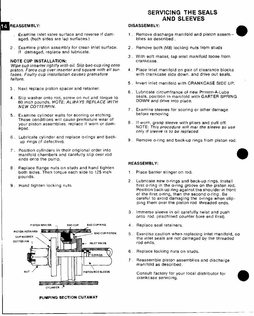
SERVICING THE SEALSAND SLEEVES
mA WEASSEMBLY:
2.
Exarnirm inlet valve surface and reverse if dam-aged. {both sides are lap surf aces.)
Examine piston assembly for clean inlet surface.If damag~d, replace and lubricate.
lWITE CUP INW”M.LAT[QN:Wipe cup Inswfer Iight/y with oii. Slip Me-cup ring ontopisfon. Force cup over inserter and square with all sur-faces. Faulty cup installation causes prematurefa)lure.
3.
4.
5.
6.
7.
%.
9.
Next replace piston spacer and retainer.
Slip washer onto rod, screw on nut and torque to60 inch pounds. NOTE: ALWAYS REPLACE WITHNEW CQT7ERPIN.
Examine cylinder walls for scoring or etching.These conditions will cause premature wear ofyour piston assemblies. replace if worn or dam-aged.
Lubricate cylinder and replace o-rings and back-up rings (if defective).
Position cylinders in their origional order intomanifold chambers and carefully slip over rodends onto the pump.
Replace flange nuts on studs and hand tightenboth sides. Then torque each side to 125 inchpounds.
Hand tighten locking nuts.
PISTON SPACER . . EIAC.CUP BAC.CUP RING
coTTER”N1 \Y
IliE--4l+--- INLET VALVE
DISASSEMBLY:
1. Remove discharge manifold and piston a.sst?m - a
2.
3.
4.
5.
6.
7.
8.
9.
blies as describ~d .
Remove both (M8) locking nuts from studs
With soft ma[let, tap inlet manifcdd lcms@ fromcrankcase.
Place inlet manifold on pair of clearance Mockswith crankcase side down. and drive out seals.
Invert inlet manifold with CRANKCASE SIDE UP.
Lubricate circumfrance of new Prrmrrn-A-Lubeseals, position in manifold with GARTER SPRINGDOWN and drive into place.
Examine sleeves for scoring or other damagebefore removing
If worn, grasp sleeve with pliers and pull off.NOTE: This procedure will mar the s[et?ve so LJiWonly it sleeve is to be replaced,
Remove o-ring and back-up rings from piston rod.
REASSEMBLY:
1
2
3
4
5
6
7
Place barrier slinger on rod.
Lubricate new o-rings and back-up rings. Installfirst o-ring in the o-ring groove on the piston rod.Position back-up ring against the shoulder in frontof the first o-ring, then the second o-ring. lilt?careful to avoid damaging the o-rings whtan slip-ping them over the piston rod threaded ends.
Immerse sleeve in oil carefully twist and pushonto rod. (machined counter bore end first].
Replace seal retainers.
Exercise caution when replacing inlet manifold, sothe inlet seals are not damaged by the threadedrod ends.
Replace locking nuts on studs.
Reassemble piston assemblies and dischargemanifold as described.
Consult factory for your local distributor forcrankcase servicing.
a
CYLINDER ~
PUMPING SEGTION CUTAWAY
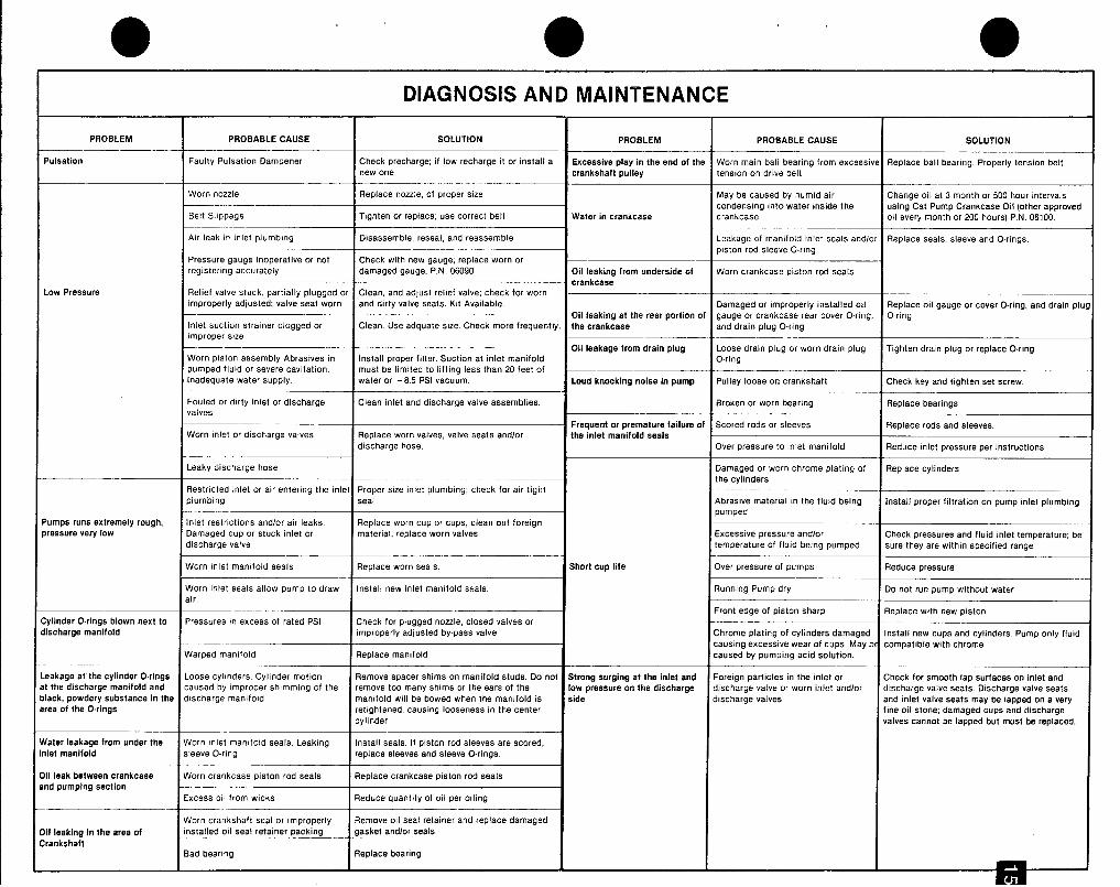
●DIAGNOSIS AND MAINTENANCE
PROBLEM PROBABLECAUSE SOLUTION PROBLEM PROBABLECAUSE SOLUTION
Pulsation Faulty PulsationDampener Check Precharge if low recharge it or install a Excessiva play in the end of tha Worn main ball bearing from excessive Replace ball bearing. Properly tenaion belt.new one crankshaft pulley tension on drive belt
Worn nozzle Replace nozzle, of proper alze May be caused by humid ah Change oIl at 3 month or 500 hour intervals
Belt Sllppage
condensing into water inside theTighten or replace; use correct belt
using Cat Pump Crankcase Oil (other approvedWater in crankcase crankcase oil every month or200houra) P. N. 06100,
Alrleakir inlet plumbing Disassemble,reseal, andreassemflle Leakage of manifold inlet seals andlm Replace seals, sleeve and O.mgs,
Pressuregauge inoperativeor not Check with new gaugq replace worn or
piston rod sleeve O.nng
registering accurately damaged gauge, P.N. 06090 Oil leaking from underside of Worn crankcase piston rod seals
Low Pressurecrankcase
Relief valve stuck, partially pluggedor Clean, andadjusl relief valve;check for wornImproperlyadjusted;valve seat worn and dirty valveseata. Kit Available. Damagedor improperlyinstalled od Replace oil gauge or coverO-ring,and drain plu
Oil leaking at tha rear portionof gauge or crankcaae rear coverO.ring,Inlet suction strainer clogged or
O-ringClean. Use adquate size. Check more frequently. the crankcase
Impropersizeand drain plug O.ring
Oil leakage from drain plug Loose drain plug or worn drain plug Tighten drain plug or replace O.ringWorn p]ston assembly Abrasivesin Install proper falter. Suction at inlet manifold O.ring
pumped fluid or severe cavitation. must be Iimited to lifting less than 20 feet ofInadequate water supply. water or -8.5 PSI vacuum. Loud knocking noise in pump Pulley Ioose on crankshaft Check key and tighten set screw.
Fouled or dirty inlet or discharge Clean inlet and discharge valve assemblies. Broken or worn bearingvalves
Replace bearings
Frequent or premature failure of Scored mds or sleeves
Worn Inlet or discharge valvesReplace rods and sleeves.
Replace worn valves, valve seats andlor the inlat manifold sealsdischarge hose. Over preaaure to inlet manifold Reduce inlet pressure per instructions
Leaky discharge hose Damaged or worn chrome plating of Replace cylindersthe cylinders
Restricted !nlet or air entering the inlet Proper size inlet plumbing; check for air tight
plumbing seal Abraswe material mthe fluid being Install proper filtration on pump inlet plumbing
Wmps runs axtremely rough,
pumped
Inlet restnctionsa ndlorair leaks. Replace worn cup or cups, clean out foreignwessure very low Damaged cup or stuck inlet or material, replace worn valves Excassive pressure andlor
discharge valve
Check pressures and fluid inlat temperature; betemperature of fluid being pumped Sure they arewithinapecified range
Worn Inlet manifold seala Replace worn seals. Short cup life Over pressure of pumps Reduce pressure—
Worn Inlet seals allow pump to draw Install new inlat manifold seals. Running Pump dry Do not run pump without water
air.Front edge of piston sharp Replace with new piston
:yfinder O.rings blown nexf to Preaaures In excesaof rated PSI Check for plugged nozzle, closed valves or
iacharge manifold !mproperly adjusted bypass valve Chrome plating of cylinders damaged Install new cups and cylinders. Pump only fluld
Warped manifold
causing excessive wear of cups. Maybe compatible with chrome
Replace manifold caused by pumping acid solution.
eakage atthe cylinder O.rings Loose cyl!nders. Cylinder motion Remove spacer shims on manifold studs. Do not Strong surging at the inlet and
t fhe discharge manifold and
Foreign particles in the inlet or check for smooth lap surfaces on inlet and
cau5ed by improper shrmming of the remove too many shims orthe ears of the low preaaure on the dischargelack, powdery substanca in fhe discharge manifold
discharge valve or worn inlet andlm discharge valve seats. Discharge valve seats
manifold will be bowed when the manifold is side d ischarge valves
rea of the O.rings retightened, causing looseness in the center
a nd inlet Valve seats may belapped on a very
cylinder
fine oil stone; damaged cups and dischargevalves cannot ba lapped but must be replaced.
later leakage from under the Worn Inlet manifold seala. Leaking Installaeals If piston rodsleevea prescored,
det manifold sIeeve O-ring replace sleeves and aleeve O.rings.
ii leak between crankcase Worn crankcase piston rod seals RePIaCe crankcase piston rod Seak
nd pumping sectionExcess 011from wicks Reduce quantity of oil per oiling
Worn crankshaft seal or Improperly Remove oil seal retainer and replace damaged
il leaking in the area of Installed oil seal retainer packing gasket andlor seala
rankahaftBad bearing Replace bearing
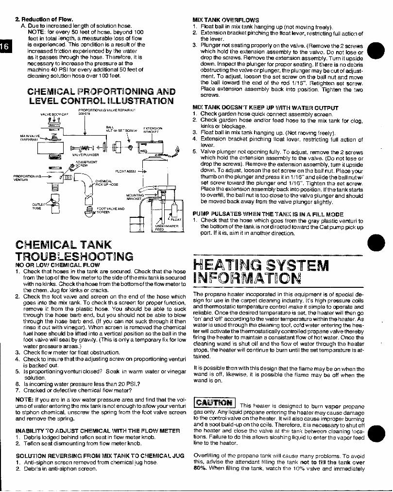
as it passes thrcwgh”tha hose. Therefore, it isnecessary to increase the pwwsure at themachine 40 PSI for eve~ additional 50 feet ofcleaning solution hos~ over 1100feet.
CHEMICAL PROPORTIONING ANDLEVEL CONTROL ILLUSTRATION
PROI=QRTIONING VALVE REPAIR KIT
PmVE
iawCHEMICAL TANKTROUBLESHOOTINGWIm LawCHEMICALFmw1.
2.
Chack that hoses in the tank are secured. Check that the hosefrom the top of the flow mieterto the sid~ of the mix tank is securedwith no kinks, Check the hose from ttm bottom of the flow meter tothe them. Jug for kinks or cracks.ICheck th~ foot valve and screen on the end of the hose whichgoes into the mix tank. To check Wis screw for proper function,remove it fmrm the plastic hose. You should ba able to suckthrough the hcwmbarb end, but you should not be able to blowthrough the hose barb end. (If you can not suck through it thenrinso it out with vinegar). When screen is removed the chemicalbsl hose should km Iifkadinto a vertical position so the ball in thefoot valve will seat by gravity. (This is only a tempora~ fix for lowwatfiwfwessuns areas.)
3. Check flmv metcwfor float obstruction.4. Check ta h’ummethat the adjusting screw on proportioning venturi
is ‘b~cked out.5. ls proportioning wimturiclmsed? Soak in warm water or vinegar
Soh.ltkm.& Is incoming waihwpressure lIsssthan 20 PSI.?7. Cracked or defective ch@micalflow meter?
IWITE!: If YOUam in a low water pressure area and find that the vol-umo of water entering the mix tank is not enough to allow your venturito siphon chemical, unsc~ew the spring from the foot valve screenand rwmmm the spring.
IEMJ3MJW To ADJUST CWWKL5L WITH THE mow METER1, Debris lodged L@tincfteflon seat in flow meter knob.2. TIMlcmsaat dismcmnting from flow meter knob.
W31JJTiClN REVERSlklG FIWWd MM TANK To CHEMICAL JUG1. Anti-siphon scnwanremoved from chemical jug hose.2. Debris in anti-siphon wmsen.
MIX TANK OVERFL~W$1. Float ball in mix tank hanging up (not moving frissdy).2. Extension bracket pinching the float lever, restricting full a@km of
the lever.3. Plunger not seating properly cmthe vakm. (Remove the 2 screws
which hold the extension assembly to th~ valve. Do not Iasti ordrop thisscrews. Remove the wtmwion assembly. Turn it upsk.ka @down. Inspect the plunger for proper seating. If tl%ra is no ckbrisobstructing the vahm or plunger, the plunger maybe nut of adj,ust-me.nt. To adjust, loosen thes@ screw on ths ball nut rarncfmowtho ball toward the end of the rod 1/1 6“. Retighten set scxww.Place wtension assembly back into position. Tighten the twoscrews.
MIX TANK DOESN’T’ KEEP UP WITH WATER CM$TPWF1.2.
3.4.
5.
Check garden hose quick connect assembly screen.Check garden hose mdlor feed hose to the mix tank far clog,kinks or blockage.Float ball in mix tank hanging up. (Not moving freely).Extension bracket pinching float lever, restricting full action oflever.Valve plunger not o~eninq fullv. To adiust, remmm tlm 2 screwswhich “hold-theextension >sse-mbly to ‘the ‘valve. (Do not lose wdrop the screws). Remove the extension assemb[y, turn it upsidedown. To adjust, loosen the setscrew on tho bait nut. Place yourthumb on the plunger and pressitin1/16“ and siide the ball nut WIset screw toward the plunger end 1/16“, Tighhan the s~t screw.Place the extension assembly back into position. If the tank starts
to overfill, the ball nut is too c[ose to the valvo plunger and shouldbe moved back away from the valve plunger slightly.
PUMP PULSATES WHEN W-METANK [$ IN A FM. MODE1.Check that the hose which goes from the gray plastic venturi to
the bottom of the tank is not directed toward the Cat pump pickupport. If it is, aim it in another direction.
HEATING SYSTEMINFORMATIONThe propane heater incoporatad in this equipment is of special d@-sign for use in the carpet cleaning industry. [t’s high pressure coilsand thermostatic temperature control make it simple to operate andreliable. One@tlw desired temperature is set, the heater’ will then go‘on’ and ‘off according to the water temperature within the heater. Aswater is used through the cleaning tool, cold water entering tlw hea-ter will ati]vate the thermostatically controlled propane valve therebyfiring the heater to maintain a consistent fiow of hot water. One@thocleaning wand is shut off and the flow of water through the heatfwstops, the heater will continue to burn until the set tempimatwe is at-tained.
It is possible th~n with this design that the flame maybe on when tlmwand is off, likewise, it is possible the flame may be off when thewand is on.
~ This beater is desicmed to burn warm mopanegas only. Any liquid propane entering tke heater may c~use damageto the control valve on the heater. It will also cause improptmburningand a soot build-upon the coils. Therefore, it is necessary to shut offthe heater and close the valve at the tank bfftween cleaning loca-tions. Failure to do this allows sloshing liquid to enter t17E3vapor feedline to the heater. o
Overfilling of the propane tank will cause many problems. To avoidthis, advise the attendant filling the tank rmt W fftil We t$snk tmmr!307.. When filling the tank, watch the 10?6 valve and imm~diately
stop filling when whke liquid starts spurting from the 107. valve. Toprevent damage to the propane regulator, always close the valve onthe tank before filling.
When venting the heater through the roof of the van, it is necessaryto install a draft diverter on top of the heater. This will prevent downdrafts from blowing out the pilot light.
The propane regulator is pre-set at the factory at 6 oz. of propane.This reading is taken at the control valve on the heater (see figure A#6). To prevent road dust and moisture from entering the propaneregulator, keep the white Tupperware cover (supplied) on the reg-ulator at all times.
To avoid restriction of air flow at base of heater, keep articles such aschemical containers, hose, boxes, etc. from within 18 inches of baseof heater. NOTE: This restricted situation also creates an over richcondition which results in soot build-up.
IMPORTANT: If a new propane tank has been installed or hoseshave been disconnected, air may enter propane hoses and must bepurged prior to attempting to light the pilot burner. Should this condi-tion exist, operator must depress the pilot button for 1-5 minutes andattempt to ignite the pilot light at 15 second intervals. A very slighthissing noise should be evident while performing this operation.
HEATER - OPERATINGINSTRUCTIONS
Heater must be Wed with watermm!z!ilpriortoignmg.A. TO START PILOT:
1. Adjust thermostat control knob on unitrol to ‘normal’. @ Fig. A.
2. Adjust upper dial to ‘pilot’ position. @Fig. A.3. Depress pilot button. @Fig. A.4. While pilot button is depressed with the left hand, use
your right hand forefinger to depress the electric spark pilotigniter button several times in rapid succession, then look tosee if pilot is lit. If not, depress in rapid succession again untillit. If this fails, use the resourceful match.
NOTE: Whenever igniting pilot, hold lit match in front of pilot sightopening before inspection. Move lit match toward pilotburner. The pilot should ignite.
IF HEATER FAILS TO LIGHT:Is propane tank full?Is propane tank valve open?Has air been properly bled from propane line?Once pilot is lit continue depressing button for 10 seconds to
insure thermo coupler has been heated.
B. TO LIGHT MAIN BURNER:1. Turn upper knob to ‘on’ position. Flame will come on.
IF NOT: Pilot has expired.Turn upper dial to ‘off position. @Fig. A.Do not attempt to relight pilot for 60 seconds.Then repeat instructions A -#1 -4.Water may already beat controlled temperature.
IF YES: Flame will turn off when thermostat senses maximum temp.
C. TO ACHIEVE PROPER CARPET CLEANINGTEMPERATURE:
1. Complete procedures A & B2. With 100’ of hose, turn cleaning wand on for 5 minutes and
the temperature should stabilize.3. Once a constant temperature is established, turn cleaning B
wand ‘off. The flame on the heater burner should remain onfor 10-15 seconds.
A. If the flame expires prior to 10 seconds, turn thethermostat dial to a higher reading, then repeat C 1-3.
B. If the flame remains lit after 15 seconds, turn thethermostat dial to a lower reading, then repeat C 1-3.
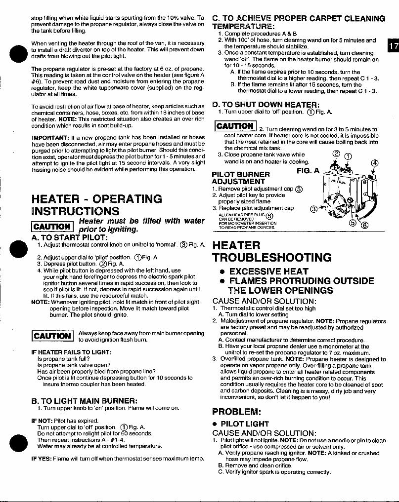
D. W SHUT 12N3WWNHEATER:1. Turn upper dial to ‘off position. @ Fig. A.
_ 2. Turncleaningwandonfor3 t05min.testocool heater core. If heater core is not cooled, it is impossiblethat the heat retained in the core will cause boiling back intothe chemical mix tank.
3. Close propane tank valve whilewand is on and heater is cooling.
PILOT BURNER FIG
ADJUSTMENT1. Remove pilot adjustment cap@2. Adjust pilot key to provide
properly sized flame3. Replace pilot adjustment cap
oALLEN HEAD PIPE PLUG ~CAN BE REMOVEDFOR MONOMETER INSERTIONTO HEAD PROPANE OUNCES.
HEATERTROUBLESHOOTING
o EXCESSWE HEATo FLAMES PROTRUDING OUTSIDE
THE ILOWER OPENINGSCAUSE ANDOR SOLUTION:1. Thermostatic control dial set too high
A. Turn dial to lower setting2. Maladjustment of propane regulator. NOTE: Propane regulators
are facto~ preset and maybe readjusted by authorizedpersonnel.
A. Contact manufacturer to determine correct procedure.B. Have your local propane dealer use a monometer at the
unitroi to re-set the propane regulator to 7 oz. maximum.3. Overfilled propane tank. NOTE: Propane heater is designed to
operate on vapor propane only. Over-filling a propane tankallows liquid propane to enter all heater related componentsand permits an over-rich burning condition to occur. Thiscondition usually requires the heater core to be cleaned of sootand carbon deposits. Cleaning is a messy, dirty job and veryinconvenient, so don’t let it happen to you!
PROBLEM:● PILOT LIGHTCAUSE AND/OR SOLUTION:1. Pilot lightwill not ignite. NOTE: Do not use a needle or pinto clean
pilot orifice - use compressed air or solvent only.A. Veri@ propane reaching igriitor. NOTE: A kinked or crushed
hose may impede propane flow.B. Remove and clean orifice.C. Verify igniter spark is operating correctly.
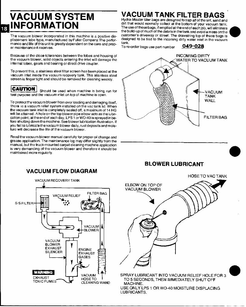
VACUUM SYSTEM~lNFORMATIoN
Tlw vacuum Mcwwwincorporated in this machine is a positive dis-placement lobe type, manufactured by Fuller Company. The perfor-marwm and life of this unit is greatly dependent on the care and prop-isrmaintiarnancait mtmives.
Bacausa of ti’m close tolerances between the lobes and housing ofthe vacuum blower, solid objects entering the inlet will darnage theinternal lobes, gears and bearing or direct drive coupler.
TCIprevent this, a stainless steel filter screen has been placed at thevacuum inlet inside the vacuum recovery tank. This stainless steelscreen is finger tight and should be removed for cleaning weekly.
~ Should be used when machine is heirm run fortest purposa and the vacuum inlet orI top of machine is op~n.
TCIprotect the vacuum Mower from overloading and damaging itself,thrwe is a vacuum relief system installed on the vac tank lid. Whenth~ vacuum tank inlet is completely sealed off, a maximum of 14 HGwi!l ‘b@attained. A hole on the top blower pipe elbow acts as the lubri-caticm point; at the end of each day, LPS 1 or WD-40 is sprayed in be-fore shutting down the machine. See blower lubrication illustration. Ifyou fail to lubricate the vacuum blower daily, rust deposits and mois-ture will decrease the life of the vacuum blower.
FMad the vacuum blower manual carefully for proper oil change andgrease application. The maintenance log may differ slightly from themanual, but the truck-mounted carpet cleaning machine applicationis very demanding of the vacuum blower and therefore it should bemaintained more regularly.
VACUUM FLOW DIAGRAM
VACUUM RECOVERY TANK
1 I
1FII-TER BAG
VACUUM RELIEF
hS/S FILTER a:**
00
A
A
wVN3JLMBLOWER w
EXHAUST= E’xcTOXIC FUMES
‘VACUUMTANK FILTER BAGS ‘Hydra-fwlashsrfilter bags are designed to trap all c#tfm lint, sand anddirt that would normally collect at the bottom of your vacmmrntank.The use of these bags, ifemptied at the end of @achjob, will fflimhvatathe build-up of much of the debris in the tank and avoid a moss on th~customer’s driveway or street. The drawstring top of thwse bags is adesigned to be tied to the incominq dirtv water irrlet in the vacuumtank.
-.
Tore-order bags use part numbw 049-02$
INCOMING DIRTY
a“”””””\
//((i VACX.JUM.
TANK
WALL
ILTER BAG
BLOWER LUBRICANT
HOSE K) VAC TANK
SPRAY LUBRICANT INTO VACUUM RELIEF HOLE FOR 3TO 5 SECONDS, THEN IMMEDIATELY SHUT OFFMACHINE.
USE ONLY LPS 1 OFI WD-4(1 MOISTURE DISPLACINGLUBRICANTS.
m
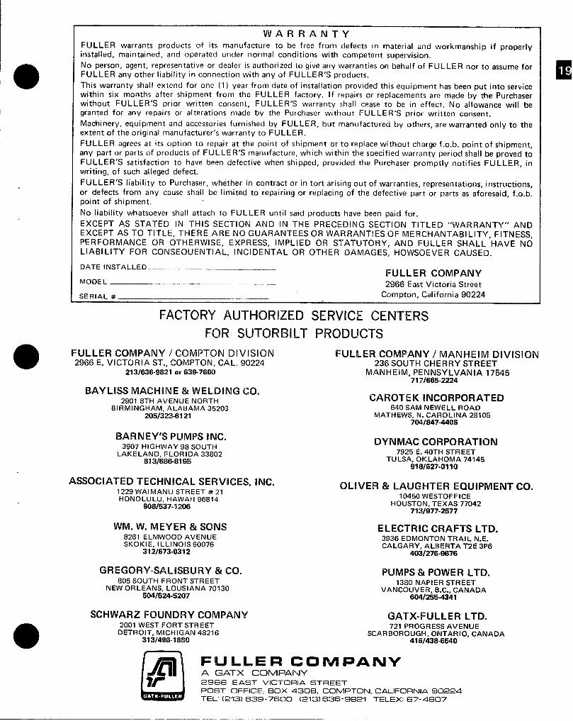
WARRANTYFULLER warrants products of its manufacture to be free from defects in material and workmanship if properlyinstalled, maintained, and operated under normal conditions with competent supervision.
No person, agent, representative or dealer isauthorized togiveany warranties on behalf of FULLER norto assume forFULLER any other liability in connection with any of FULLER’S products.
This warranty shall extend for one (1) year from date of installation provided this equipment has been put into servicewithin six months after shipment from the FULLER factory. If repairs or replacements are made by the Purchaserwithout FULLER’S prior written consent, FULLER’S warranty shall cease to be in effect. No allowance will begranted for any repairs or alterations made by the Purchaser without FULLER’S prior written consent.
Machinery, equipment and accessories furnished by FULLER, but manufactured by others, are warranted only to theextent of the original manufacturer’s warranty to FULLER.
FULLER agrees at its option to repair at the point of shipment or to replace without charge f.o.b. point of shipment,
any part or parts of products of FULLE R’S manufacture, which within the specified warranty period shall be proved toFULLER’S satisfaction to have been defective when shipped, provided the Purchaser promptly notifies FULLER, inwriting, of such alleged defect.
FULLER’S liability to Purchaser, whether in contract or in tort arising out of warranties, representations, instructions,or defects from any cause shall be limited to repairing or replacing of the defective part or parts as aforesaid, f.o.b.point of shipment,
No liability whatsoever shall attach to FULLER until said products have been paid for.
EXCEPT’ AS STATED IN THIS SECTION AND IN THE PRECEDING SECTION TITLED “WARRANTY” ANDEXCEPT AS TO TITLE, THERE ARE NO GUARANTEES OR WARRANTIES OF MERCHANTABILITY, FITNESS,PERFORMANCE OR OTHERWISE, EXPRESS, IMPLIED OR STATUTORY, AND FULLER SHALL HAVE NOLIABILITY FOR CONSEQUENTIAL, INCIDENTAL OR OTHER DAMAGES, HOWSOEVER CAUSED.
DATE installed ______FULLER COMPANY
MODEL ____ 2966 East Victoria Street
SERIAL #——--–- Compton, California 90224
FACTORY AUTI-ICRL?ED SERVICE CENTERS
FOR SLJTOF?BILT PRODUCTS
a FULLER COMPANY / COMPTON DIVISION FULLER COMPANY / MANHEIM DIVISION2966 E. VICTORIA ST., COMPTON, CAL. 90224 236 SOUTH CHERRY STREET
2131636-9821 or 639-7’600 MANHElM. PENNSYLVANIA 17545“7771665-2224
BAYLISS IMACHINE & WELDING CO.2901 8TH AVENUE NORTH CAROTEK INCORPORATED
BIRMINGHAM, ALABAMA 35203 640 SAM NEWELL ROAD
205/323-61 21 MATHEWS, N. CAROLINA 2810570418474406
BARNEY’S PUMPS INC.3907 HIGHWAY 98 SOUTH
DYNMAC CORPORATION
LAKE LAND, FLORIDA 33802 7925 E. 40TH STREET
81 3/686-819!5 TULSA, OKLAHOMA 74145918f627-lM 10
ASSOCIATED TECHNICAL SERVICES, INC.1229 WAIMANU STREET #21HONOLULU, HAWAll 96814
8081537-1206
OLIVER %sLAUGHTER EQUIPMENT CO.10450 WESTOFFICE
HOUSTON, TEXAS 770427131977-2577
WM. W. MEYER & SONS ELECTRIC CRAFTS LTD.8261 ELMWOOD AVENUESKOKIE, IL LINOIS 60076
3936 EDMONTON TRAIL N.E.
312/673-0332CALGARY, ALBERTA T2E 3P6
403f276-8676
GREGORV-SALISBURY & CO. PUMPS & POWER LTD.805 SOUTH FRONT STREET
NEW ORLEANS, LOUSIANA 701301380 NAPIER STREET
5041524-6207VANCOUVER, B. C., CANADA
604/255-4341
SCHWARZ FOUNDRY COMPANY GATX-FULLER LTD.2001 WEST FORT STREET 721 PROGRESS AVENUE
DETROIT, MICHIGAN 48216 SCARBOROUGH, ONTARIO, CANADA373/496-7880 416/438-6540
od+ril FLJLLIEFB C~MPANYA GATX COMPANY
W 2966 EAST VICTORIA STREETPOST OFFICE, BOX 430B, COMPTONJ, CALIFORNIA 90224
TEL: [=?=] 639-7600 (Q131 636-9821 TELEX: GT-4607
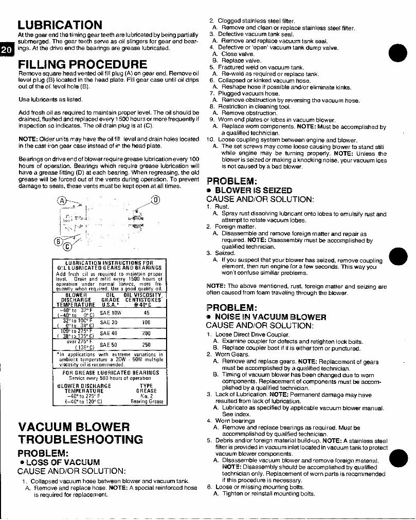
At the gear end the timing gear teath are lubricated by being partially
m
subrrrewged.The graartw?th serve as oil slingers for gear end bear-
0 ings. At this drive end the bearings are grease lubricated.
FILLING PROCEDUREl%rnove squzwshead vented oil fill plug (A) on gear end. Remove oillevel plug (B) located in the head plate. Fill gear case until oil dripsout ctfthe oil lev@lhale (B).
Use lubricants as listed.
Add Mmh oil as required to maintain proper k?vei.The oil should bedrained, flushed and rr@aced every 1500 hours or more frequently ifinspection so indicates. The oil drain plug is at (C).
Nt3TE: CMJer units may have the oil fi!l level and drain holes locatedin the cast iron gear case instead of in the head plate.
Bearings on drive end of blower require grease lubrication every 100hours of operation. Bearings which require grease lubrication willhave a greasa fitting {13) at each bearing. VVhen regressing, the oldgrease will be forced out of the vents during operation. To preventdamage to soaks, these vents must be kept open at all times.
LIJBHICATION INSTRUCTIONS FOROIL l. IDBFliICATEDGEARS AND BEARINGS
Add fresh oil as required to maintain proparleml. Orain and refill every 1500 hours ofoporation under normal service, more fre.quently when required. Use a good quality oil.
BLOWER OIL OIL VISCOSITYDISCHARGE GRADE CEN&S’l&KES’
TEMPERATURE U.S.A.*
~~j$;~ 3;[) SAE 10W 45
K!”to 100°F( O“to 38”C)
SAE 20 100
100’ to275° F38°to 135” c) ‘AE 40 200
over275°F( 135” C)
SAE 50 250
*ln applications with axtreme variations inambient temperature a 20W 50W multiplevisco$ityoil is recommended.
FOR GREASE LMBRICATEO BEARINGSServiceevery 500 hours of operation
8LOWER DISCHARGE TYPETEMFERATUFIE GREASE
–40” to 275” F No. 2(–@o”to 12W’C) BearingGrease
VACIJIJMBLOWERTROUBLESHOOTINGFwmmul:a~~s~QFv~cu~~
CAUSE AND/CWl SOLUTION:1. Collapsed vacuum hose between blower and vacuum tank.A. FMmave and replace hose. hKYl%R A special reinforced hose
is required for ~eplacement.
2. Clogged stainless steel filter.A. Remove and clean or replace stainless st~el filter.
3. Defective vacuum tank seal.A. Remove and replace vacuum tank seal.
4. Defective or ‘open’ vacuum tank dump valve.A. Close valve.B. Replace valve.
5. Fractured weld on vacuum tank.A. Re-weld as required or replace tank.
6. Collapsed or kinked vacuum hose.A. Reshape hose if possible ar?d/or eliminate kinks.
7. Plugged vacuum hose.A. Remove obstruction by reversing th~ vacuum hose.
8. Restriction in cleaning tool.A. Remove obstruction.
9. Worn end plates or lobes in vacuum blower.A. Replace worn components. NOTE: Must be accomplished by
a qualified technician,10. Loose coupling system between engine and blower.
A. The set screws may come loose causing blower to stand stillwhile engine may be turning properly. NOTE: Unless theblower is seized or making a knocking noise, your vacuum lossis not caused by a bad blower.
‘PFmmuEllwl:@BLOWER 1SSEKZEDCAUSE AND/OR SOLUTION:1. Rust.
A. Spray rust dissolving lubricant onto lobes to emulsify rust andattempt to rotate vacuum lobes.
2. Foreign matter.A. Disassemble and remove foreign matter and repair as
required. NOTE: Disassembly must be accomplished byqualified technician.
3. Seized.A. If you suspect that your blower has seized, remave coupling
aelement, then run engine for a few seconds. This way youwon’t confuse similiar problems.
NOTE: The above mentioned, rust, foreign matter and s@izingamoften caused from foam traveling through the blower.
PROBLEM :@NOLSE IN VACUUM BLCNVEB3CAUSE AND/CW! SOLUTION:1. Loose Direct Drive Coupler.
A. Examine coupler for defects and rsdighten lock boks.B. Replace coupler boot if it is either torn or punctured.
2. Worn Gears.A. Remove and replace gears. NOTE: Replacement of gears
must be accomplished by a qualified technician.B. Timing of vacuum blower has been changed clue to worn
components. Replacement of components must be accom-plished by a qualified technician.
3. Lack of Lubrication. NOTE: Permanent damage may havaresulted from lack of lubrication.
A. Lubricate as specified by applicable vacuum blower manual.See index.
4. Worn bearingsA. Remove and replace bearings as r~quired. Must be
accomplished by qualified technician.5. Debris and/or foreign material build-up. NOTE: A stainkms steel
filter is provided in vacuum inlet Iocat@din vacuum t~k to pr@@~tvacuum blower components.
A. Disassemble vacuum blower end remove foreign material.NOTE: Disassembly should be accomplished by qualified a
technician only. Replacement of worn parts is recommw’wkfif this procedure is necessary.
6. Loose or missing mounting bolts.A. Tighten or reinstall mounting bolts.
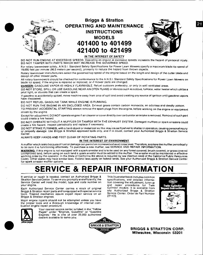
Briggs & Stratton -%w%--...OPERATING AND MAINTENANCE (
INSTRUCTIONS d
MODELS
401400 to 401499421400 to 421499
IN THE INTEREST OF SAFETY.. . ..— —. -.. —.DO NOT RUN ENGINE AT EXCESSWE SPEEDS. Operating an engine at excessive weeds increases the hazard of personal injury.DO NOT TAMPER WITH PARTS WHICH MAY INCREASE THE GOVERNED SPEED.
For rotary Iawnmower safety, A. N.S. I. Standard Safety Specifications for power Lawn Mowers specify a maximum blade tip speed of19,000 feet per minute (96.5 meters per second), primarily to reduce the hazard from thrown objects.
Rotary Iawnmower manufacturers select the governed top speed of the en9ine based on the length and design of the cutter blade anddesbgn of other mower parts.All rotary Iawnmowers should be checked for conformance to the A. N.S. I. Standard Safety Specifications for Power Lawn Mowers onblade tip speed, if the engine is repaired or replaced, or if mower parts are changed.
DANGER: GASOLINE VAPOR IS HIGHLY FLAMMABLE. Refuel outdoors preferably, or only in well ventilated areas.DO NOT STORE, SPILL OR USE GASOLINE NEAR AN OPEN FLAME or devices such as a stove, furnace, water heater which utilize apilot light, or devices that can create a spark.
If gasoline is accidentally spilled, move machine away from area of spill and avoid creatin9 any source of ignition until gasoline vaporshave dissipated.
DO NOT REFUEL GASOLINE TANK WHILE ENGINE IS RUNNING.
DO NOT RUN THE ENGINE IN AN ENCLOSED AREA. Exilaust gases contain carbon monoxide, an odorless and deadly poison.TC) PREVENT ACCIDENTAL STARTING always remove the spark plugs from the engine, before working on the engine or equipment
driven by the engine.
Except for adjustment; DO NOT operate engine if air cleaner orcoverdirectly over carburetor air intake is removed. Removal of such partcould create a fire hazard.
DO NOT OPERATE WITHOUT A M,UFFLEROR TAMPEFI WITH THE EXHAUST SYSTEM. Damaged mufflers or spark arresters couldcreate a fire hazard. Inspect periodically and replace If necessary.DO NOT STRIKE FLYWHEEL with a hard objector metal tool as this may,cause flywheel to shatter in operation, causing personal injuryor property damage. Use Briggs & Stratton approved tools only, and If m doubt, contact your Authorized Briggs & Stratton ServiceCenter.ALWAYS KEEP HANDS AND FEET CLEAR OF ROTATING PARTS.
IN THE INTEREST OF ENVIRONMENT
A muffler which leaks because of rust or damage can permit an increased exhaust noise leVel. Therefore, examine the muffler periodical yto be sure it is functioning effectively. To purchase a new muffler, see SERWCE AND REPAIR INFORMATION.
WARNING: If this engine is not equipped with a spark arrester and is to be used on any fOre5t covered, brush covered, or grass coveredunimproved land, before using on such land a spark arrester must be added to the muffler. The arrester must be maintained in effectiveworking order by the operator. In the State of California the above is required by law (Section 4442 of the California Public ResourcesCode). Other states may have similar laws. Federal laws apply on federal lands. See your Authorized Briggs & Stratton Service Centerfor spark arrester muffler options.
SERVICE & REPAIR INFORMATIONIf service or repair is needed, contact an Authorized Briggs & This illustrated book includes commonStratton Service Center. To serve you promptly and efficiently, the specifications, and detailed informa-Service Center will need the model, type and code number on tion covering the adjustment, tune-upyour engine. and repair procedures for TwinEach Authorized Service Center carries a stock of original Cylinder models. It is available from
Briggs & Stratton repair parts and is equipped with special service any Authorized Briggs & Stratton
tools. Trained mechanics assure expert repair service on all Service Center. Order as Part Number
Briggs & Stratton engines. 271172.
Major engine repairs should not be attempted unless you havethe proper tools and a thorough knowledge of internal com-bustion engine repair procedure.
m
Your nearest service center is listed in the “YellowPages” under “Engines, Gasoline” or “GasolineEngines.” He is one of over 25,000 authorizeddealers avaiiable to serve you.
WJWPs!WBRIGGS & STRAITON
w’BRIGGS & STRATTON CORP.
Milwaukee, Wisconsin 53201
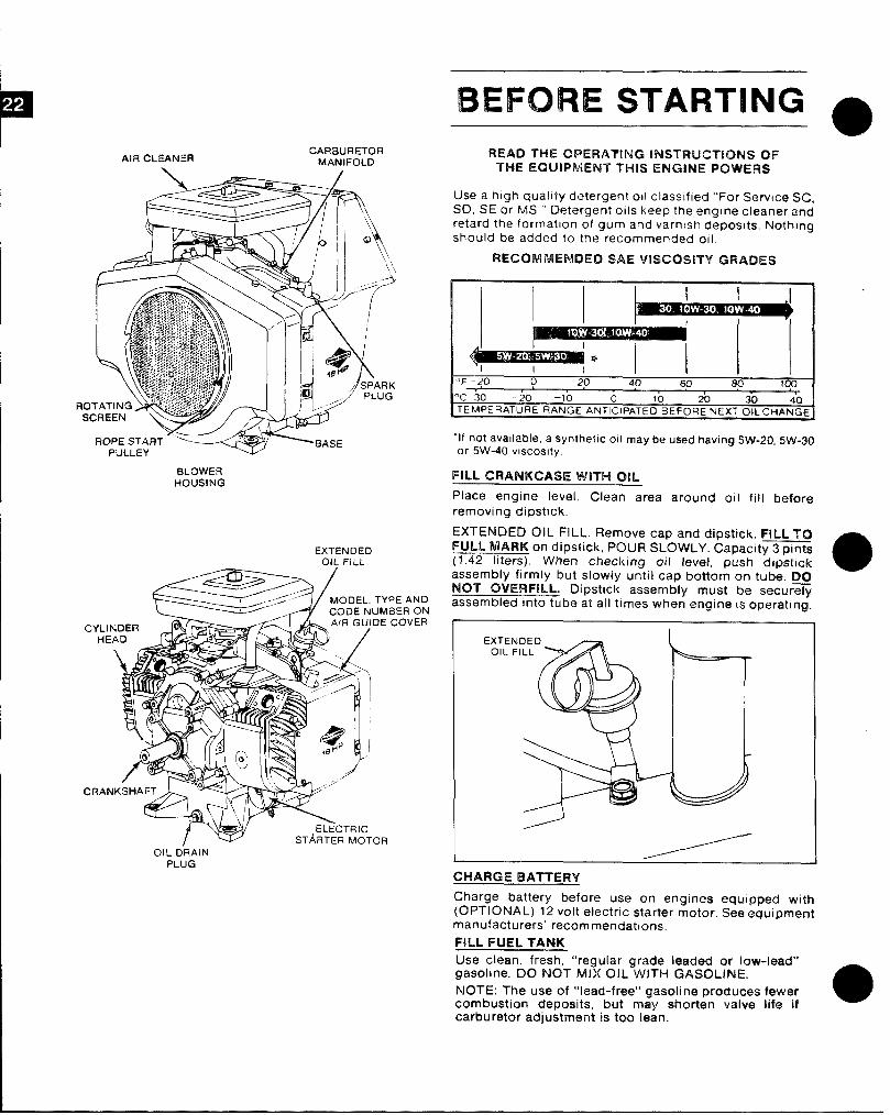
Ali? CLEANERCARBURETOR
MANIFOLD
mPE START - “—~
PULLEY-r .Wb
HLOWERHOUSING
BEFORE STARTINGa
READ THE OPERATING INSTRUCTIONS OFTHE EQUIPMENT THIS ENGINE Pt2WERS
Use a high quality detergent 011 classified “ForService SC,SC), SE or MS. ” Oetergent OIIS keep the engine cleaner andretard the formation of gum and varnish deposits, Nothingshould be added to the recommended 011
RECOMMENDED SAE Vlscosmf GRADES
‘F 20 0 20 40 m 80 lCO
“c 30 20 –lo o 10 20 30 40TEMPERATuRE RANGE ANTICIPATED BEFORE NEXT OIL CHANGE
“If not available, a synthetic oli may b% used hawng 5W-20, 5W-30or 5W-40 vwcoslty.
FILL CRANKCASE WITH OIL
Place engine level. Clean area around oil fill before
removing dipstick,
EXTENDED OIL FILL, Remove cap and dipstick. FILL TOFULL MARK on dipstick, POUR SLOWLY. Capacit-s(1 ,42 liters). When checking oil level, push dipstick
aassembly firmly but slowly until cap bottom on tube. DjlNOT OVERFILL. Dipstick assembly must be securelyassembled Into tube at all times when engine w operating.
EXTENDED
OIL FILL
EXTENOIL F
OIL DRAINPLUG
CHARGE BATTERY
Charge battery before use on eng~nes equipp~d with(OPTIONAL) 12 volt electric starter motor. See equipmentmanufacturers’ recommendations.
FILL FUEL TANK
Use clean, fresh, “regular grade leaded or low-lead”gasoline. DO NOT MIX OIL WITH GASOLINE.
NOTE: The use of ‘“lead-free” gasoline produces fewercombustion deposits, but may shorten valve life ifcarburetor adjustment is too tean.
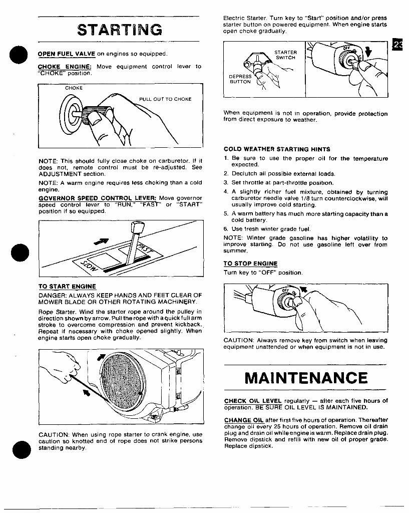
STARTING
o OPEN FUEL VALVE on engines so equipped—
CHOKE ENGINE: Move equipment control lever to“CHOKE” position.
CHOKE
PULL OUT TO CHOKE
NOTE: This should fully close choke on carburetor. If itdoes not, remote control must be re-adjusted. SeeADJUSTMENT section.
NOTE: A warm engine requires less choking than a coldengine.
GCVERNOR SPEED CONTROL LEVER: Move governorst)eed control lever to “RUN,” “FAST” or “START”position if so equipped.
TO START ENGINE
DANGER: ALWAYS KEEP HANDS AND FEET CLEAR OFMOWER BLADE OR OTHER ROTATING MACHIN~RY.
Rope Starter. Wind the starter rope around the pulley indirection shown by arrow. Pull the rope with a quick full armstroke to overcome compression and prevent kickback..Repeat if necessary with choke opened slightly. Whenengine starts open choke gradually.
CAUTION: When using rope starter to crank engine, use
a caution so knotted end of rope does not strike personsstanding nearby.
Electric Starter. Turn key to “Start” position and/or pressstarter button on powered equipment. When engine startsopen choke gradually.
10--OFF
STARTER
% %
SWITCH t
DEPRESSBUTTON .+
When equipment is not in operation, provide protection
from direct exposure to weather.
COLD WEATHER STARTING HINTS
1.
2.
3.
4.
5.
6.
Be sure to use the proper oil forexpected.
Declutch ail possible external loads.
Set throttle at part-throttle position.
the temperature
A slightly richer fuel mixture, obtained by turningcarburetor needle valve 1/$ turn counterclockwise, willusually improve cold starting.
A warm battery has much more starting capacity than acold battery.
Use fresh winter grade fuel.
NOTE: Winter grade gasolineimprove starting. Do not usesummer.
TO STOP ENGINE
Turn key to ‘IOFF” position.
has higher volatility togasoline left over from
CAUTION: Always remove key from switch when leavingequipment unattended or when equipment is not in use.
MAINTENANCECHECK OIL LEVEL regularly — after each five hours ofoperation. BE SLJRE OIL LEVEL IS MAINTAINED.
CHANGE OIL after first five hours of operation. Thereafterchange oil every 25 hours of operation. Remove oil drainplug and drain oil while engine iswarm. Fleplacedrain plug.Remove dipstick and refill with new oil of proper grade.Replace dipstick.
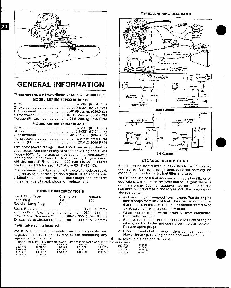
. ,,,.rr \.
\ ‘LA = b---“% /- ) “B” 1’—--- _.—”
“D”
GENERAL INFORMATIONThese engines are two-cylinder L-head, air-cooled type.
MODEL SERIES401400to 401499Bore. . . . . . . . . . . . . . . . . . . . . . . . . . . . . ..3-7/16’’ (87.31 mm)Stroke . . . . . . . . . . . . . . . . . . . . . . . . . . . ..2-5/32’’ (54.77 mm)Displacement . . . . . . . . . . . . . . . . . ..4t10cucin in. (656.0 CC)Horsepower . . . . . . . . . . . . . . . . . . 16 HP Max. @3600 RPfvfTorque (Ft,-Lbs. ) . . . . . . . . . . . . . . . 25.8 Max. @2700 RPfM
MQDEL SERIES 421400 tO 42T499
Bore.. . . . . . . . . . . . . . . . . . . . . . . . . . . . . .3-7/16’’ (87.31 mm)Stake . . . . . . . . . . . . . . . . . . . . . . . . . . . . .Displacement . . . . . . . . .
2-9/32” (57.94 mm}. . . . . . . . . . 42.33 cu. in. (694.0 cc)
Horsepower . . . . . . . . . . . . . . . . . . . . . . . 18 f-fP@3600RpMTorque (Ft.-Lbs.) . . . . . . . . . . . . . . . . . . .. 28.6 @2600 RPfM
?he horsepower ratings listed above are established inaccordancowith the Societyof Automotive Engineers TestCode-J607. For practical operation, the horsepowerIoading should notexceed85?b ofthisrating. Engine powerwill decrease S%”/O for each 1,0010 feet (304.8 m) aboveSealeveiand l%for,each 10° above60° F(16° C).
lnsomearea~,local lawrequiresthe useofaresistor sparkplug seas to suppress ignition signals. lfan engine wasoriginally equipped withresistorspark plugs,besureto usethesame type of spark plugs for replacement.
TUNE-LIP SWECIFICMTIONS
Spark PIug Type Champion AutoliteLong Plug J-8 295Flesistor Long Plug RJ-8 306
Spark Plug Gap . . . . . . . . . . . . . . . . . . . . . . . ..030’’ (.76 mm)lgnit~on Po~nt Gap . . . . . . . . . . . . . . . . . . . . . ..020’’ (.51 mm)Intake Valve Clearance”* . . . . . . .004’’ -. 0(6’’(.l O-.l5mm)Exhaust Valve Clearance “*. . . . . .007’’ -,00(,18,23 mm)3mm)
““with valve spring installed.
WARNING, For electrical safety always remove cable fromnegative (-) side of the battery before attempting anyrepairs or ma~ntenance,
TrbClmult
STORAGE INSTRUCTIONS
Engines to be stored over 30 days should be completelydrained of fuel to prevent gum deposits forming anessential carburetor parts, fuel fitter and tank.
NOTE: The use of a fuel additive, such as STA-131L, or’ anequwalent, will minim izetheformation of fuel gum depositsduring storage. Such an additive may be add&d to thegasoline in the fuel tank of the engine, ortothegasalino ina ~storage container.
a. ‘All fue[ should be removed from the tank. Run theerngineuntil it stops from lack of fuef. The smafl amount of fuel
b,
c.
d,
6 e.BRIOGS & STRATTON ENGINES ARE MAOE uNo ER ONE OR MORE OF THE FOLLOWING PATENTS
28,960 3.149618 3,276439 3,526,146 3625.071 3831 268 39688542,999,491 3,194224 3305223 3572.218 3650354 3882336 3971 .753
that remains in the sump of the tank should be removed
by absorbfng It with a clean, dry cloth.
While engine is still warm, drain oil from crankcase.Refill with fresh oil.Remove spark plugs, pour one ounce (29 6CC) ofenglrw011 Into each cyl]nder and crank slowly to distribute ml,Replace spark plugs,
Clean dirt and chaff from cyllnders, cyllnder head ftns,blower housing, rotating screen and muffler areas,
Store In a clean and dry area.
2.999,562 3,236937 3,457804 3572307 3 745.3933.114,851 3242741
3,901 1993,465740
3991 1523625492 3738345 3,961 724 4 168288
3.118,433 3252449
a
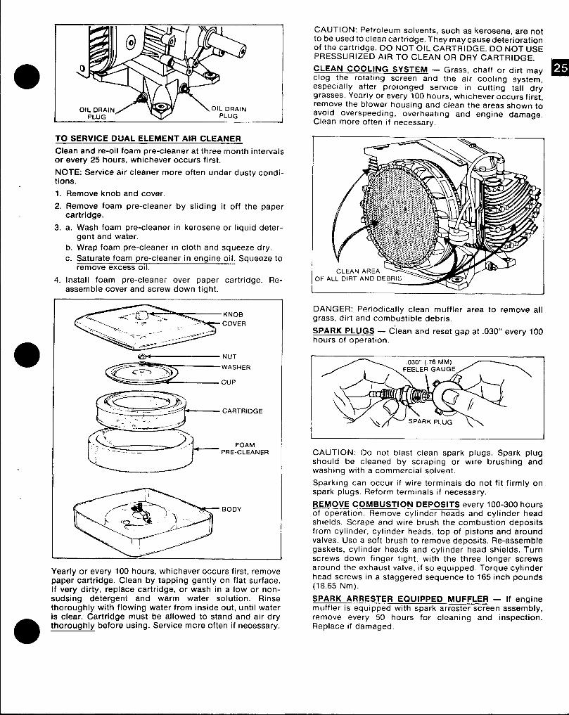
9
TO SERVICE DUAL ELEMENT AIR CLEANER
Clean and re-oil foam pre-cleaner at three month intervalsor every 25 hours, whichever occurs first.
NOTE: Service air cleaner more often under dusty condi-tions.
1. Remove knob and cover.
2. Remove foam pre-cleaner by sliding it off the papercartridge.
3. a. Wash foam pre-cleaner in kerosene or liquid deter-gent and water.
b. Wrap foam pre-cleaner in cloth and squeeze dry.
c. Saturate foam pre-cleaner in engine oil. Squeeze toremove excess 011.
4. Install foam pre-cleaner over paper cartridge. Re-assemble cover and screw down tight
-. . ..- CARTRIDGE
“— “-
FOAMPRE-CLEANER
Yearly or every 100 hours, whichever occurs first, removepaper cartridge. Clean by tapping gently on flat surface.If very dirty, replace cartridge, or wash in a low or non-sudsing detergent and warm water solution. Rinsethoroughly with flowing water from inside out, until wateris clear. Cartridge must be allowed to stand and air drythoroughly before using. Service more often if necessary.
CAUTION: Petroleum solvents, such as kerosene, are notto be used to clean cartridge. They maycause deteriorationof the cartridge. DO NOT OIL CARTRIDGE. DO NOT USEPRESSURIZED AIR TO CLEAN OR DRY CARTRIDGE.
CLEAN COOLING SYSTEM — Grass, chaff or dirt mayclog the rotating screen and the air cooling system,especially after prolonged service in cutting tall drygrasses. Yearly or every 100 hours, whichever occurs first,remove the blower housing and clean the areas shown toavoid overspeeding, overheating and engine damage.Clean more often if necessary.
DANGER: Periodically clean muffler area to remove allgrass, dirt and combustible debris,
SPARK PLUGS — C’”lean and reset gap at .030” every 100hours of operation.
I 1
CAUTION: Do not blast clean spark plugs. Spark plugshould be cleaned by scraping or wire brushing andwashing with a commercial solvent.
Sparking can occur if wire terminals do not fit firmly onspark plugs. Reform terminals if necessary,
REMOVE COMBUSTION DEPOSITS every 100-300 hoursof operation. Remove cylinder heads and cylinder headshields. Scrape and wire brush the combustion depositsfrom cylinder, cylinder heads, top of pistons and aroundvalves. Use a soft brush to remove deposits. Re-assemblegaskets, cylinder heads and cylinder head shields. Turnscrews down finger tight, with the three longer screwsaround the exhaust valve, if so equipped. Torque cylinderhead screws in a staggered sequence to 165 inch pounds(18.65 Nm).
SPARK ARRESTER EQUIPPED MUFFLER — If enginemuffler is equipped with spark arrester screen assembly,remove every 50 hours for cleaning and inspection.Replace if damaged.
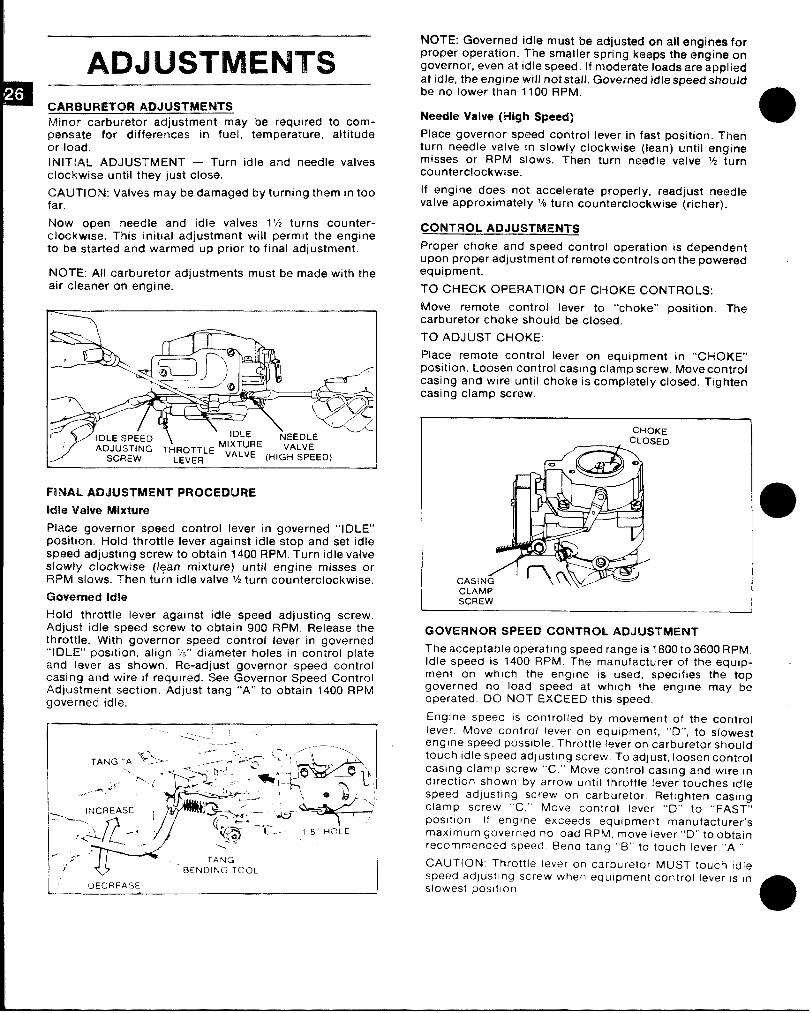
ADJUSTMENTSCARBURETOR ADJUSTMENTSMinor carburetor adjustment may be required to com-pensate for differences in fuel, temperature, altitudeor load.
INITIAL ADJUSTMENT — Turn idle and needle valvesclockwise until they just close.
CAIJTION: Valves may be damaged by turning them in toofar.
Now open needle and idle valves 1 ‘h turns counter-clockwise, This initial adjustment will permit the engineto be started and warmed up prior to final adjustment.
NOTE: All carburetor adjustments must be made with theair ckwtner on ‘engine. -
FINAL, ADJUSTMENT PROCEDURE
Idle Vahm Mixtuw
Place governor speed control lever in governed “IDLE”position. Hold throttle lever against idle stop and set idleSpewl adjusting screw to obtain 1400 RPM. Turn idle valveslowly clockwise (lean mixture) until engine misses orRPM slows. Then turn idle valve ‘/2 turn counterclockwise.
t2mN?rll@d Idle
Hold throttle lever against idle speed adjusting screw,Adjust idle speed screw to obtain 900 RPM. Release thethrottle. WJith governor speed control lever in governed“IDLE” posjtion, align %“ diameter holes in control plateand lever as shown. Re-adjust governor speed controlcasing and wire if required. See Governor Speed ControlAdjustment section. Adjust tang “A” to obtain 1400 RPMgoverned idle.
1’ DECRFAS’E I
NOTE: Governed idle must be adjusted on all ongirtes forproper operation. The smaller spring keeps tho engine ongovernor, even at idle speed. If mod.arate loads are appliedat idle, the engine will not stall. Governed idle speed shouldbe no lower than 1100 RPM.
Needle Valve (High Speed)
Place governor speed control lever in fast position. Thenturn needle valve In slowly clockwise (lean) until enginemisses or RPM slows. Then turn needle valve M turncounterclockwise.
If engine does not accelerate properly, readjust ntmdlevalve approximately % turn counterclockwise (richer).
CQNTROL ADJUSTMENTS
Proper choke and speed control operation IS dependentupon proper adjustment of remote controls on the poweredequipment.
TO CHECK OPERATION OF CHOKE CONTROLS:
Move remote control lever to “choke” position. Thecarburetor choke should be closed.
TO ADJUST CHOKE:
Place remote control lever on equipment in “CHOKE”’pcsition. Loosen control casing clamp screw. Move controlcasing and wire until choke is completely closed. Tightencasing clamp screw.
CtiOKF
CLAMP.\--
SCREW
GOVERNOR SPEED CONTROL ADJUSTMENT
The acceptable operatlnq s~eed ranae IS ?800t03600 RPM,Idle speed is 1400 RPM- T’he manu~acturer of the equ!p-ment on which the engtne IS used, specifies the topgoverned no load speed at wh[ch the engine may beoperated. DO NOT EXCEED this speed,
Engine speed IS controlled by movement of the controllever Move contro( lever on equipment, “O”, to slow~sfengine speed possible Throttle lever on carburetor shoutdtouch Idle speed adjusting screw. To adjust, loosen controlcasing clamp screw “C.”’ Move control casing and wtre Indlrectlon shown by arrow until throttle lever touches Idlespeed adlusting screw on carburetor. Retighten casingclamp screw “C.” Move control lever “D” to ‘<FAST”posltlon. If engine exceeds equipment manufacturer’smaximum governed no load RPM, move lever “D” Ioobtalnrecommended speed Bend tang “B” to touch lever “A.”
CAUTION Throttle lever on carburetor MUST touch tdlespeed adjusting screw when equipment control lever IS in
slowest posltlon.
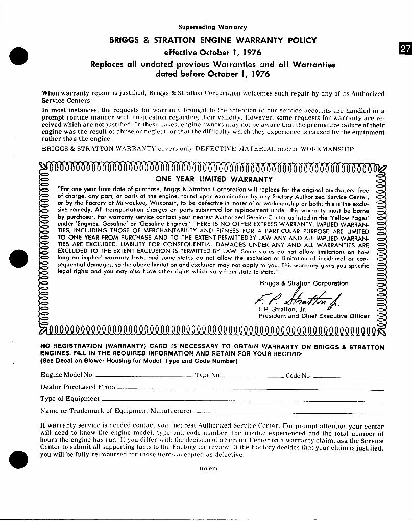
Superseding Warranty
BIUGGS & STRAT7’ON ENGINE WARRANTY POLICY
o effective October 1, 1976
Replaces all undated previous Warranties and all Warrantiesdated before October 1, 1976
When warranty repair is justified. Briggs & Stratton Corporation welcomes such repair by any of its AuthorizedService Centers.
In most instances, the requests for warranty brought to the attention of our service accounts are handled in aprompt routine manner with no question regarding their validity. However. some requests for warranty are re-ceived which are not justified. In these cases. engine owners may not be aware that the premature failure of theirengine was the result of abuse or neglect. or that the difficulty which they experience is caused by the equipmentrather than the engine.
BRIGGS & STRATTON WARRANTY covers only DEFECTIVE MATERIAL tind/or WORKMANSHIP.
ONE YEAR LIMITED WARRANTY“For one year from date of purchase, Briggs & Stratton Corporation will replace for the original purchasers, free
of charge, any part, or parts of the engine, found upon examination by any Factory Authorized Service Center,or by the Factory at Milwaukee, Wisconsin, to be defective in material or workmanship or both; this is-the exclu-sive remedy. All transportation charges on parts submitted for replacement under thjs warranty must be borneby purchaser. For warranty service contact your nearest Authorized Service Center as listed in the ‘Yellow Pages’
under ‘Engines, Gasoline’ or ‘Gasoline Engines.’ THERE IS NO OTHER EXPRESS WARRANTY. IMPLIED WARRAN-
TIES, INCLUDING THOSE OF MERCHANTABILITY AND FITNESS FOR A PARTICULAR PURPOSEARE LIMITEDTO ONE YEAR FROM PURCHASE AND TO THE EXTENT PERMITTED BY LAW ANY AND ALL IMPLIED WARRAN.TIES ARE EXCLUDED. LIABILITY FOR CONSEQUENTIAL DAMAGES UNDER ANY AND ALL WARRANTIES ARE
●EXCLUDED TO THE EXTENT EXCLUSION IS PERMITTED BY LAW. Some states do not allow limitations on howlong an implied warranty lasts, and some states do not allow the exclusion or limitation of incidental or con-
sequential damages, so the above Iimitatian and exclusion may not apply to you. This warranty gives you specificlegal rights and you may also have other rights which vary from state to state.”
NO REGISTRATION (WARRANTY) CARD IS NECESSARY TO OBTAIN WARRANTY ON BRIGGS & STRATTONENGINES. FILL IN THE REQUIRED INFORMATION AND RETAIN FOR YOUR RECORD:(See Decal on Blower Housing for Model, Type and Code Number)
Engine Model No. Type No. Code No.
Dealer Purchased From
Type of Equipment
Name or Tracfemark of Equipment Manufacturer
If warranty service is needed contact your ne:lrest Authorized Service Center. For prompt attention your centerwill need to know the engine model. type and code number. the trouble experienced and the total number ofhours the engine has run. If you differ with the decision of a Service Center on a warranty claim. ask the ServiceCenter to submit all supporting f~lcts to the Factory for review. If the Factory decides tha_t your claim is justified,
m
you will be fully reimbursed for those items accepted as defective.
(o\’er)
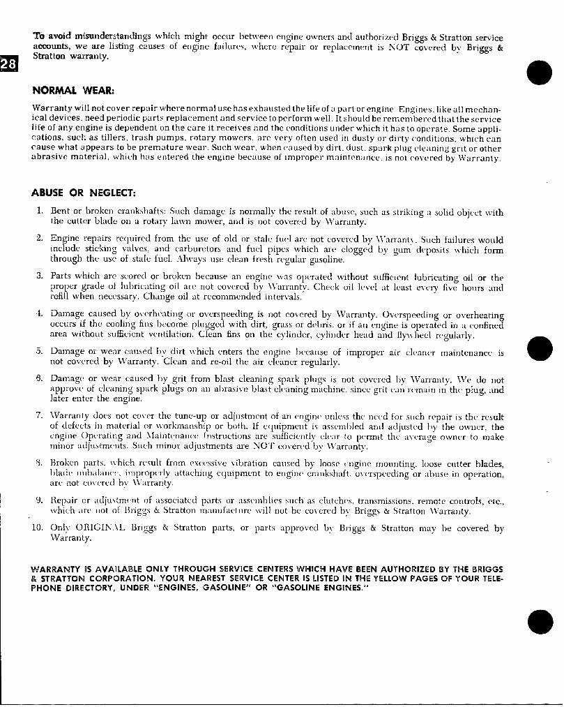
❑a*
~a avoitl mismderstandimgs which might occur between engine owners and authorizrcl Briggs & Stratton serviceacommts, we are listing causes of engine failures, where repair or replacement is NOT covered by !3ri~s &Stratton warranty.
NWMAL WEAR:
Warranty wil[ not cover repair where normal use hasexhaustedthe life of a part or engine. Engines, like a[l mechan-ical devices, need periodic parts replacement and serviceto perform well. It should be remembered that the servicelife of any engine is dependent on the care it receives and the conditions under which it has to operate. Some appli-cations, such as tillers, trash pumps, rotary mowers, are very often used in dusty or dirty conditions. which cancause what appears to be premature wear. Such wear, when caused by dirt. dust, spark plug cleaning grit or otherabrasive material, which has entered the engine because of improper maintenance. is not cw~’ered by Warranty,
ABUSE OR NEGLECT:
2.
I 3.
I -1.
I 5.
I 6.
I 7.
I w
10,
Brnt or broken crankshafts: Such damage is normally the result of abuse, such as striking a soIid object withthe cutter black on a rotary lalvn mower, and is not covered by \Varranty.
Engine repairs rquircd from the use of old or stale fm>l arc not covered by lVarranty. Such failures wouldinclude sticking va[ves, and carburetors and fuel pipes which are clogged by gum d(~posits tvhich formthrough the use of stale fuel. .Always use cIwn fresh regular gasoline.
Parts which are scorecl or broken !wcause an engine was opc>ratecl without sufficient lubricating oiI or theproper grade of Iubricat ing oi 1 are not covered by \\’arranty. Check oil level at least ev(>ry five hours ondrefill when necessary. Change oil at recommended intervals.
Damage caused by o~whcating or overspeeding is not covered by TVarranty, Ov<’rspecding or overheatingoccurs if the cooling fins become plugged with dirt, grass or dt>bris, or if an engine is operat[’d in a confinedarea without sufficient ventilation. Clean fins on the cylinder, cylinclcr head and fiywhecl rx’gularly.
Damage or wear caused by dirt \vhich cmters the engine becausr of improper air cleaner maintenance isnot covered by lVarranty. Clean and re-oil the air cleaner regularly,
e
Damage or wear caused by grit from blast cleaning spark plugs is not covered by lVarranty. \ve do l]otapprovt~ of cleaning spark plugs on an abrasive blast cleaning machine, since grit cm] remain in th(’ plug, a]]dlater entm the engine.
lVarranty does not cover the tune-up or a(ljustrncnt of an (mgin{ unl(ws the ncxd for such repair is the resultof defects i]) material or workmanship or both. If c(luipmcnt is ass(mll)led and adjust(, d l)v the owner, thecmgint’ Op(’rating and \laintcmance Instructions arc s(lfficicmtly cl(ar to p(mnit the a~x’rag~ owner to makeminor acljustmwts. Such minor adjustments are NOT covered by kVarranty.
13rolwm parts. ~thich result from exc{,ssive vibration ca~]sed by IOOSC(ngine mo~lnting, loosr clltter blades,blad[’ Ilnlmlallc(’. impropi’rly attaching c(]uipment to engine crankshaft, uv(~rspetding or abuse in operation,arr not cot(’rc(l I)y \Varranty.
Repair or adimsttn(mt of associated parts or asselnblies such as clutches, transmissions, remote controls, etc.,which tw( not of Briggs & Stratton manufactllrc, \vilI not I]c coi(m’d by Briggs & Stratton lf’arranty.
OrLly ORICIIN:\L Briggs & Stratton parts, or parts approved b? Briggs & Stratton ]nav be cwered bykVarrantyu
WARRANTY !S AVAILABLE 0NL% THROUGH SERVICE CENTERS WHICH HAVE BEEN AUTHORIZED BY THE BRIGG$& STRATTON CORPORATION. Y~UR NEAREST SERVICE CEN’TERIS LISTED IN THE YELLOW PAGES OF YOUR Telep-hone DIRECTORY, UNDER “ENGINES, GASOI.INE” OR “GASOf.lhfE ENGINES.”
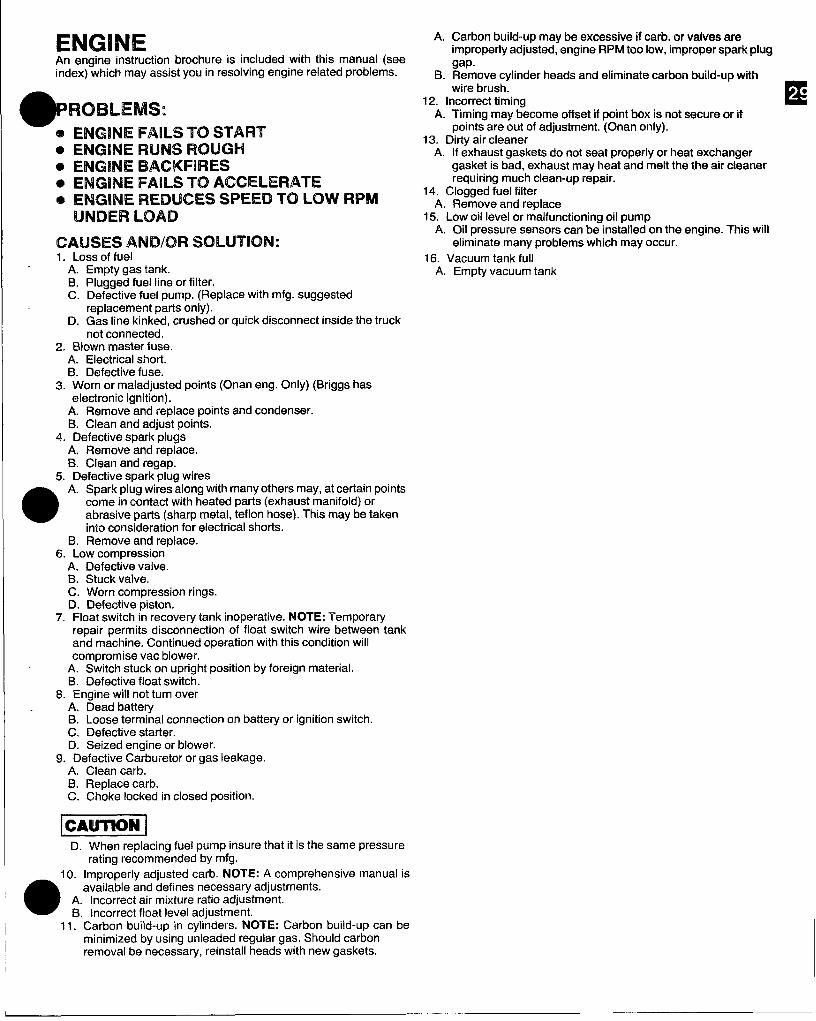
ENGINEArr engine instruction brochure is included with this manual (seeindex) which may assist you in resolving engine related problems.
*ROBLEMS:
@ENGINE FAILS “m STARTo IENGH4E RUNS ROUGHo ENGINE BACKFIRESID ENGINE FAILS TO ACCELERATE* ENG!NE REDUCES SPEED TO Low RPM
UNDER ILOAD
CAUSES AND/OR SOLUTION:1. Loss of fuel
A. Empty gas tank.B. Plugged fuel line or filter.C. Defective fuel pump. (Replace with mfg. suggested
replacement parts only).D. Gas line kinked, crushed or quick disconnect inside the truck
not connected.2. Blown master fuse.
A. Electrical short.B. Defective fuse.
3. Worn or maladjusted points (Onan eng. Only) (Briggs haselectronic ignition).
A. Remove and replace points and condenser.B. Clean and adjust points.
4. Defective spark plugsA. Remove and replace.B. Clean and regap.
5. Defective spark plug wires
a
A. Sparkplug wires along with many others may, at certain pointscome in contact with heated parts (exhaust manifold) orabrasive parts (sharp metal, tefIon hose). This maybe takeninto consideration for electrical shorts.
B. Remove and replace.6. Low compression
A. Defective valve.B. Stuck valve.C. Worn compression rings.D. Defective piston.
7. Float switch in recovery tank inoperative. NOTE: Temporaryrepair permits disconnection of float switch wire between tankand machine. Continued operation with this condition willcompromise vac blower.
A. Switch stuck on upright position by foreign material.B. Defective float switch.
8. Engine will not turn overA. Dead batteryB. Loose terminal connection on battery or ignition switch.C. Defective starter.D. Seized engine or blower.
9. Defective Carburetor or gas leakage.A. Clean carb.B, Replace carb.C. Choke locked in closed position.
A.
B.
Carbon build-up may be excessive if carb. or valves areimproperly adjusted, engine RPM too low, improper spark pluggap.Remove cylinder heads and eliminate carbon build-up withwire brush.
E●
12. Incorrect timingA. Timing may ~ecome offset if point box is not secure or if
points are out of adjustment. (Onan only).13. Dirty air cleaner
A. If exhaust gaskets do not seat properly or heat exchangergasket is bad, exhaust may heat and melt the the air cleanerrequiring much clean-up repair.
14. Clogged fuel filterA. Remove and replace
15. Low oil level or malfunctioning oil pumpA. 011pressure sensors can be installed on the engine. This will
eliminate many problems which may occur.16. Vacuum tank full
A, Empty vacuum tank
D. When replacing fuel pump insure that it is the same pressurerating recommended by mfg.
10. Improperly adjusted carb. NOTE: A comprehensive manual is
a
available and defines necessary adjustments.A. Incorrect air mixture ratio adjustment.B. Incorrect float level adjustment.
11. Carbon build-up in cylinders. NOTE: Carbon build-up can beminimized by using unleaded regular gas. Should carbonremoval be necessary, reinstall heads with new gaskets.
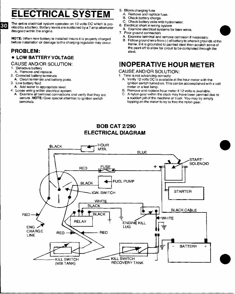
ELECTRICAL SYSTEMTha smtire ehsctrical system operates cm 12 volts DC which is pro-vidad by a bathery. Battwy levels are sustained by a 7 amp alternatordemigrwd within the engine.
NOTE: W1’risnmaw battery is installed insure it is properly chargedWore installation m damage to the cha~ging regulator may occur.
PROBLEM:
@ LOW H~lTIEFly VOLTAGE
CAUSE ANWOFI SOLUTION:1. Defective battery
A. Remove and replace.2. Corroded battery terminals
A. Clean te!rnmirnalsand battery pasts.3. Low battery fluid
A. Add water to appropriate level.4. Loose wiring within electrical system.
A. Examine all terminal connections and verify that they aresecure. NOTE: Give special attention to ignition switchterminals.
5. Blown charging fuseA. Remove and replace fuse.B. Check batteiy charge.C. Check battery cells with hydrometer.
6. Electrical short in wiring systemA. Examine eiecttical systems for bare wires.
7. Poor ground connection aA. Examine terminal and remove corrosion if necossa~.B. Follow ground wire from (-) of battery to where itgrounds at ttwa
frame. 1$it is grounded to painted steel then scratch some ofthe paint off to allow for circuit to be ccwn@et@dthrough ttmsteel.
INOPERATIVE HOUR METERCAUSE AND/OR SOLUTION:1. Time IS not advancing correctly
A.
B.c.
Verify 12 volts DC is availatile at the ~~ur meter with theignition switch turned on. This can be accomptisheci with a voltmeter or a test lamp.Remove and replace hour meter if 12 volts is available.A nylon gear within the clock may have been iammed due toa sudden jolt of the machine or truck. You may try simplytapping on the meter to try to free the nylon gear.
BOB CAT 2/290ELECTRICAL DIAGRAM
BLACK HOURMTR.
BLUE#l N
l\
a’”ELpuMp_ IGN. SWITCH
WHITE“LACK
‘?11? BLACK CABLE
ncu
3EmCHAFWIELINE
RED
(MIX TANK) RECOVERY TANK
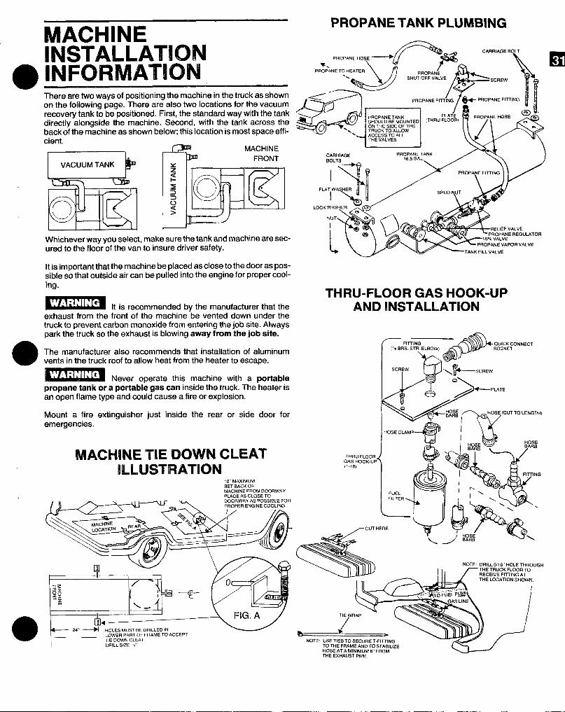
MACHINEPROPANE TANK PLUMBING
INSTALLATIONINFORMATIONThere are two ways of positioning the machine in the truck as shownon the following page. There are also two locations for the vacuumrecovey tank to be positioned. First, the standard way with the tankdirectly alongside the machine. Second, with the tank across theback of the machine as shown below; this location is most space effi-cient.
MACHINE
Whichever way you select, make sure the tank and machine are sec-ured to the floor of the van to insure driver safety.
It is important that the machine be placed as close to the door as pos-sible so that outside air can be pulled into the engine for proper cool-ing.
It is recommended by the manufacturer that theexhaust from the front of the machine be vented down under thetruck to prevent carbon monoxide from entering the job site. Alwayspark the truck so the exhaust is blowing away from the job site.
The manufacturer also recommends that installation of aluminumvents in the truck roof to allow heat from the heater to escape.
1“’1-’.’m,.
Never o~erate this machine with a portablepropane tank or a portable gas can inside the truck. The-heater isan open flame type and could cause afire or explosion.
Mount a fire extinguisher just inside the rear or side door foremergencies.
MACHINE ‘TIE li30WWNCLEATllmAAstnRA-mN
10 MAXIMUMSET BACK OFMACHINE FROM DOORWAY
---->
J-35’ 1~, /PROPANE FIT+NG
— &
BOLT
\/ j&-Pf30PANEFim(Nc3
-m ‘“”d
SHOULD BE MOUNTED (THBu FLOOR)
CARRIAGE PRIJ&.:::ANKan, -e / \\
F’”~q [// ‘“”y ~
‘OcK‘ASHY&
THRU-FLOOR GAS HOOK-UPAND INSTALLATION
hi?FITTING
&
QUICK CONNE.T(,%SRS. STR ELBOW) SOCKET
G
SCREW, /.\&
lb-k-’A 2-PUT’
RW3u9
/HOSEBARS
HOSE (CUT TO LENGTH)
HOSE CIAMP ,,<< /
i
HOSE ‘““ HOSE
“Rs G
E)ARS
THRu FLOORGAS HOOK.UP(1-10) “19 Y’
F?’Wc- r-&/FITTING
P.FUELFILTER l’,
L&\
L’
c%—NOTE: uSE TIES TO SECURE T-FITTING
TO THE FRAME AND TO STABILIZEHOSE AT A MINIMUM 6’ FROMTHE EXHAUST PIPE.
-QYJ!9!Y’/---’G---J
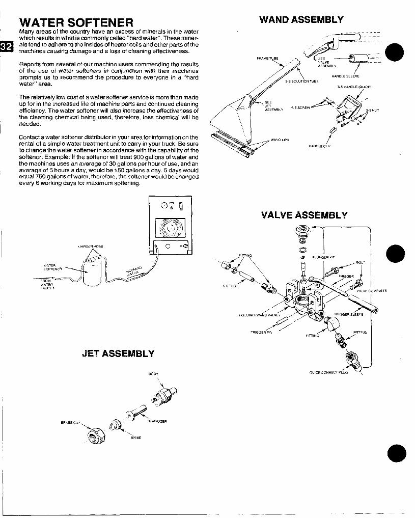
WATER SOFTENER WAt+dDASSEMBLYMany areas of the country have an excess of minerals in the waterwhich results in what is commonly called “hard water”. These miner-als tend to whsre to the insides d heater coils and other parts of themachimas causing damag~ and a lass of cleaning effectiveness. \,/,&~:_:@
FRAME TUBE
FlaPcIrts from sevw’al of our machine users commending the results.-+
.ASSEM13LY
I of ~ht+use af wab.m’softc$nersin conjuntilon with the~r machinesprompts us to recmnm~nd the procedure to everyone in a “hard ,/’\ iHANOLE SLEEVE
water” area.5S SOLUTION TUBE
S S HANDLS [QU&OE)
The relatively law cost of a water softener service is more than made
/<
\up for in the increased life of machine parts and continued cleaning ~ :;:
SSXREWAefficiency. The water sofkmer will also increase the effectiveness of
‘\ ‘/ ,’. ::,/ ASSEMBLY ‘s NU1
the cleaning chemical being used, therefore, less chemical will be \,,needed. \
Contact a water softener distributor in your area for information on therental of a simple water treatment unit to carry in your truck. Be sureto change the water softener in accordance with the capability of thesdhwkw. Example: If the softener will treat 900 gallons of water andthe machines uses an average of 30 gallons per hour of use, and anaverage of 5 hours a day, would be 150 gallons a day. 5 days wouldequal 7!30 gallons of water, therefore, th@softener would be changedevery Gworking days for maximum softening.
-:.$9 “FAuCET
&’WAND LIPS
tbi&NDLE CLIP
BRASS C&P
JET ASSEMBLY
BODY
VALVE ASSEMBLY
.. mLIZTE
@QJx“QUICK CONNECT PLuG \
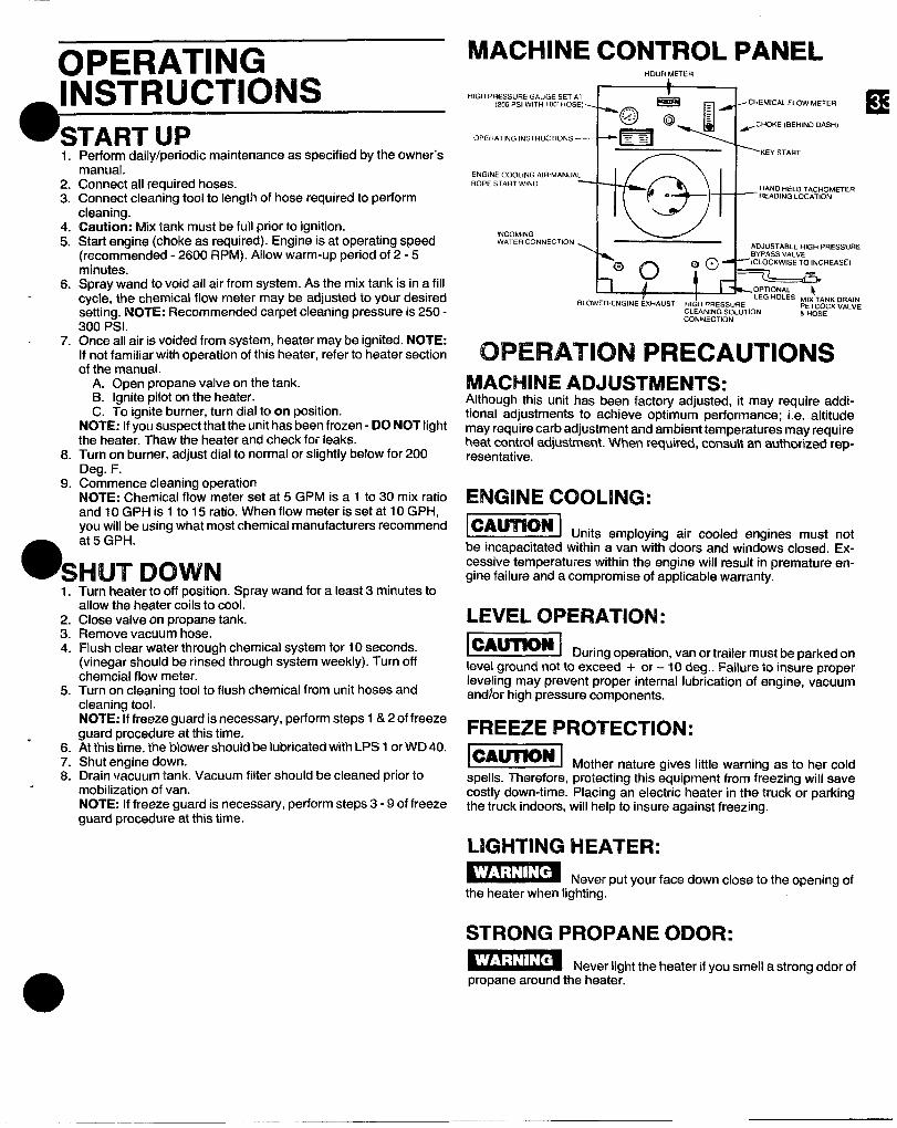
OPERATINGINSTRUCTIONSSTART UP1.
2.3.
4.5.
6.
7.
8.
9<
Perform daily/periodic maintenance as specified by the owner’smanual.Connect all required hoses.Connect cleaning tool to length of hose required to performcleaning.Caution: Mix tank must be full prior to ignition.Start engine (choke as required). Engine is at operating speed(recommended -2600 RPM). Aliow warm-up period of 2-5minutes.Spray wand to void all air from system. As the mix tank is in a fillcycle, the chemical flow meter may be adjusted to your desiredsetting. NOYE: Recommended carpet cleaning pressure is 250-300 Psi.Once all air is voided from system, heater maybe ignited. NOTE:If not familiar with operation of this heater, refer to heater sectionof the manual.
A. Open propane valve on the tank.B. Ignite pilot on the heater.C. To ignite burner, turn dial to on position.
NOTE: If you suspect that the unit has been frozen-DO NOT lightthe heater. Thaw the heater and check for leaks.Turn on burner, adjust dial to normal or slightly below for 200Deg. F.Commence cleanirm o~erationNOTE: Chemical fl~w “meterset at 5 GPM is a 1 to 30 mix ratioand 10 GPH is 1 to 15 ratio. When flow meter is set at 10 GPH,vou will be usina what most chemical manufacturers recommend
O&5 GPH. -
SHUT DOWNI1.
2.3.4.
5.
*6.7.8.
Turn heater to off position. Spray wand for a least 3 minutes toallow the heater coils to cool.Close valve on propane tank.Remove vacuum hose.Flush clear water through chemical system for 10 seconds.(vinegar should be rinsed through system weekly). Turn offchemcial flow meter.Turn on cleaning tool to flush chemical from unit hoses andcleaning tool.NOTE: If freeze guard is necessary, perform steps 1 & 2 of freezeguard procedure at this time.At this time, the biower should be lubricated with LPS 1 orWD 40.Shut engine down.Drain vacuum tank. Vacuum filter should be cleaned prior tomobilization of van.NOTE: If freeze guard is necessary, perform steps 3-9 of freezeguard procedure at this time.
MACHINE
HIGH PRESSURE GAuGE SET AT(200 PSI WITH $00 HOSE)>
CONTROL PANELHOUR METER
a ~w
T I LEG HOLES ~lx ~*NK DRAINBLOWER, E.GINE ExHAusT HIGH PRESSURE
CLEANING sOLUT10.PETCOCK VALVE& HOSE
CONNECTION
OPERATION PRECAUTIONSMACHINE ADJUSTMENTS:Although this unit has been factory adjusted, it may require addi-tional adjustments to achieve optimum performance; i.e. altitudemay require carb adjustment and ambient temperatures may requireheat control adjustment. When required, consu\t an authorized rep-resentative.
ENGINE COOLING:
_ Units employing air cooled engines must notbe incapacitated within a van with doors and windows closed. Ex-cessive temperatures within the engine will result in premature en-gine failure and a compromise of applicable warranty.
LEVEL OPERATION:
Durina o~eration. van or trailer must be ~arked onlevel ground not to exce%d’ + or – 10 deg.. Failure to ins~re properleveling may prevent proper internal lubrication of engine, vacuumand)or high pressure components.
FREEZE PROTECTION:
~ Mother nature gives little warning as to her coldspells. Therefore, protecting this equipment from fr=ezing will savecostly down-time. Placing an electric heater in the truck or parkingthe truck indoors, will help to insure against freezing.
LIGHTING HEATER:
Never put your face down close to the opening ofthe heater when lighting.
STRONG PROPANE ODOR:
Never light the heater if you smell a strong odor ofpropane around the heater.
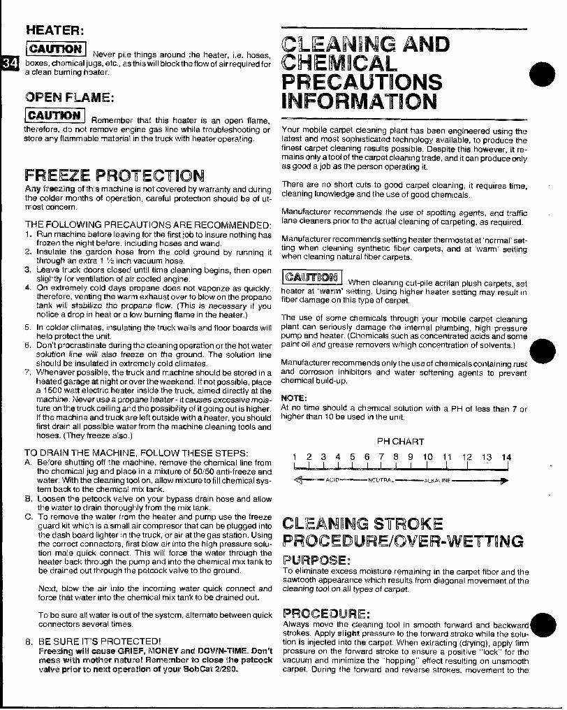
HEATER:
~ I%evar pk3 things around the Iwater, i.e. hosas,boxes, chemical jugs, etc., as this will block the flow of air required fora clean burning Iwlu@r.
OPEN FLAME:
lQ?wENJRternelrnbw thatthis heater is an open flame,therefore, do not remove engine gas limewhile troubleshooting orstore any flammable material in the truck with heater operating.
FREEZEPROTECTIONAny fre~zing of this machine is not covered by warranty and duringtl’m colcfar months of operation, cafieful protection should be of ut-most cmnccwn.
THE FOLLOWING PRECALJTICXNS ARE RECOMMENDED:1.
2.
3.
4,
!5.
6.
7.
Run machine before Ioaving for the first job to insure nothing hasfrozen the night before, including hoses and wand.Insulate the garden hose from the cold ground by running itthrough an extra 1 % inch vacuum hose.L@av+etruck doors closed until time cleaning begins, then openslightly for ventilation of air cooled ‘engine.On extwmwly cold days propane does not vaporize as quickly,thmefo~e, venting the warm exhaust over to blow on the propanetank will stabilize thra propane flow. (This is necessary if younotico a drop in l’mat or a low burning flame in the heater, )
In colder climates, insulating the truck wails arid floor boards willhelp pmtf?ct ttw w-lit.Don’t procrastinate during the cleaning operation or the hot watersalution line will also freeze on the ground. The solution lineshould btr insulated in extremely cold climates.Whenever possible, the truck and machine should be stored in atvaatd gfwage at night or over the weekend. If not possible, placea 1500 watt electric heater inside the truck, aimed directiy at themachine. Nrmmruse a propane heater-it causes excessive mois-tum on the truck ceiling and the possibility of it going out is higher.If the machine and truck are left outside with a heater, you shouldfirst drain all possible water from the machine cleaning tools andhoses. (They freeze also.)
TCl DRAIN THE MACHINE, FOLLOW THESE STEPS:A.-’ “ ‘“ ‘“s “
.,, . . . .
B.
c
8.
Bemre snumng on me macnme, remove me cnemlcal Ime wornthe chemical jug and place in a mixture of 50/50anti-freeze andwater. With tt%acleaning tool on, allow mixture to fill chemical sys-tem back to the chemical mix tank.Loosen the petcock valve on your bypass drain hose and allowthe water todrain thoroughly from the mix tank.To remove the water from the heater and pump use the freezeguard kit which is a small air compresor that can be plugged intothe clash board lighter in the truck, or air at the gas station. Usingthe correct connectors, first blow air into the high pressure solu-ticm male quick connect. This will force the water through theheater back through the pump and into the chemical mix tank tobe drakwd out through the petcock valve to the ground.
Next, MOW the air into the incoming water quick connect andforce that water into the chemical mix tank to be drained out.
To bo sure all water is out of the system, aiternate between quickccmnec$orsseveral times.
HE SURE IT’S PFlOTECTED!I%waxing will cause? GRIEF, MONEY and DOWN-TIME. Don’t
mess ‘with mothw’ nature! !WlwxmbW to UAXW the petcock
valve pIFkw to rmxt ,qmerath-t 0$ your EWKat 2/290.
CLEANINGANDCHEMICALPRECAUTIONSINFORMATIONYour mobile carpet cleaning plant has b~en engineered using thelatest and most sophisticated technology available, to produce thefinest carpet cleaning results possible. Despite this however, it re-mains only a tooi of the carpet cleaning trade, and it can produce onlyas good a job as the person operating it,
There are no short cuts to good carpet cleaning, it requires time,cleaning knowiedge and the use of good chramicals.
Manufacturer recommends the use of spotting agents, and trafficlane cleaners prior to the actual cleaning of carpeting, as r~quired.
Manufacturer recommends setting heater thermostat at ‘normal’ s@t-ting when cleaning synthetic fiber carpets, and at ‘warm’ settingwhen cleaning natural fiber carpets.
~ Wh en cieaning cut-pii~ acrilan plush carpets, setheater at ‘warm’ setting. Using bighw heater setilng may resuit infiber damage on this type of carpet.
The use of some chemicals through your mobile carpet cleaningplant can seriously damage the internal plumbing, high prmsurepump and heater. (Chemicais such as concentrated ac~dsand some _paint oil and grease removers wihigh concentration of solvwts.)
Manufacturer recommends only the use of chemicals containing rust eand corrosion inhibitors and water softening agents to Dr&ventchemical build-up.
NOTE:At no time should a chemical solution with a pH of less than 7 orhigher than 10 be used in the unit.
PI-4 CHART
1234567891011 121314I I I i I I i I I I J
4— ACl@ —NEUTRAL— “’h’’”’~
.
CLEANING STROKEPROCEDURE/OVER-WETTINGPURPOSE:To eliminate excess moisture remaining in the carpet fiber and thesawtooth appearance which results from diagonal movement of thecleaning tool on all types of carpet.
PROCEDURE:Always move the cleaning tool in smooth forward and backwardstrokes. Apply slight pressure to the forward stroko whii~ tl’m soiu- 0tion is injected into the carpet. When extracting (drying), apply firmpressure on the forward stroke to ensure a positive “lock” for thevacuum and minimize the “hopping” effect resulting on unsmoothcarpet. During the forward and reverse strokes, movement to the
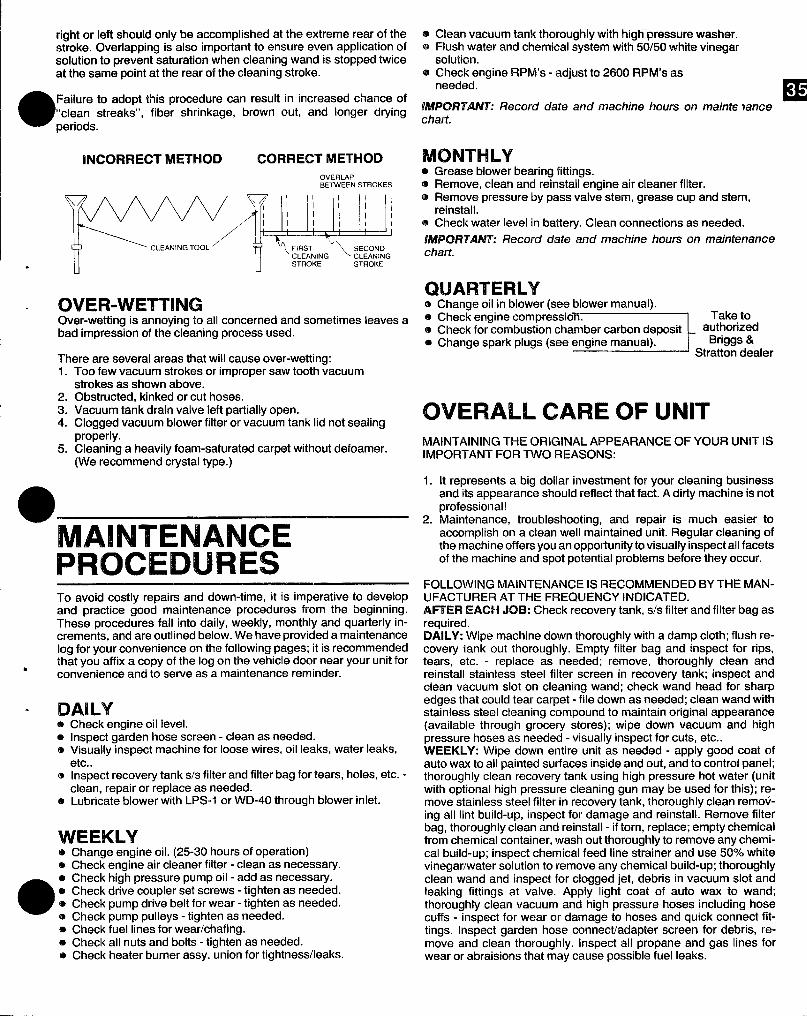
right or left should only be accomplished at the extreme rear of thestroke. Overlapping is also important to ensure even application ofsolution to prevent saturation when cleaning wand is stopped twiceat the same point at the rear of the cleaning stroke.
e Failure to adopt this procedure can result in increased chance of“clean streaks”, fiber shrinkage, brown out, and longer dving
periods.
INCORRECT METHOD CORRECT METHODOVERLAPBETWEEN STROKES
\/—
%YYfxq/qJJ&!,;CLEANING
. STROKE STROKE
OVER-WETTINGOver-wetting is annoying to all concerned and sometimes leaves abad impression of the cleaning process used.
There are several areas that will cause over-wetting:1. Too few vacuum strokes or improper sawtooth vacuum
strokes as shown above.2. Obstructed, kinked or cut hoses.3. Vacuum tank drain valve left partially open.4. Clogged vacuum blower filter or vacuum tank lid not sealing
properly.5. Cleaning a heavily foam-saturated carpet without defoamer.
(We recommend crystal type.)
●—
MAINTENANCEPROCEDURESTo avoid costly repairs and down-time, it is imperative to developand practice good maintenance procedures from the beginning.These procedures fall into daily, weekly, monthly and quarterly in-crements, and are outlined below. We have provided a maintenancelog for your convenience on the following pages; it is recommendedthat you affix a copy of the logon the vehicle door near your unit fornconvenience and to serve as a maintenance reminder.
DAILY@ Check engine oil level.e Inspect garden hose screen - clean as needed.e Visually inspect machine for loose wires, oil leaks, water leaks,
etc..o Inspect recovery tank s/s filter and filter bag for tears, holes, etc. -
clean, repair or replace as needed.o Lubricate blower with LPS-I or WD-40 through blower inlet.
WEEKLYChange engine oil. (25-30 hours of operation)Check engine air cleaner filter - clean as necessary.Check high pressure pump oil - add as necessary.Check drive coupler set screws - tighten as needed.Check pump drive belt for wear - tighten as needed.Check pump pulleys - tighten as needed.Check fuel lines for wear/chafing.Check all nuts and bolts - tighten as needed.Check heater burner assy. union for tightness/leaks.
a Clean vacuum tank thoroughly with high pressure washer.@ Flush water and chemical system with 50/50 white vinegar
solution.@ Check engine M%4’s - adjust to 2600 FIPM’s as
needed.m
LWWRTANT: Record date and machine hours on mairrte lancechart.
MONTHLY● Grease blower bearing fittings.aI Remove, clean and reinstall engine air cleaner filter.@ Remove pressure by pass valve stem, grease cup and stem,
reinstall.@ Check water level in battey. Clean connections as needed.
M%W3T.AFW: Record date and machine hours on maintenancechart.
QUARTERLYs change oil in blower (see blower manual).
‘—}j&&,er
e Check engine compression.e Check for combustion chamber carbon deposite Change spark plugs (see engine manual).
OVERALL CARE OF UNITMAINTAINING THE ORIGINAL APPEARANCE OF YOUR UNIT ISIMPORTANT FOR TWO REASONS:
1. It represents a big dollar investment for your cleaning businessand its appearance should reflect that fact. A dirty machine is notprofessional!
2. Maintenance, troubleshooting, and repair is much easier toaccomplish on a clean well maintained unit. Regular cleaning ofthe machine offers you an opportunity to visually inspect all facetsof the machine and spot potential problems before they occur.
FOLLOWING MAINTENANCE IS RECOMMENDED BY THE MAN-UFACTURER AT THE FREQUENCY INDICATED.AFTER EACH JOB: Check recovey tank, s/s filter and filter bag asrequired.DAILY: Wipe machine down thoroughly with a damp cloth; flush re-covery tank out thoroughly. Empty filter bag and inspect for rips,tears, etc. - replace as needed; remove, thoroughly clean andreinstall stainless steel filter screen in recovery tank; inspect andclean vacuum slot on cleaning wand; check wand head for sharpedges that could tear carpet - file down as needed; clean wand withstainless steel cleaning compound to maintain original appearance(available through grocery stores); wipe down vacuum and highpressure hoses as needed - visually inspect for cuts, etc..WEEKLY: Wipe down entire unit as needed - apply good coat ofauto wax to all painted surfaces inside and out, and to control panel;thoroughly clean recovery tank using high pressure hot water (unitwith optional high pressure cleaning gun may be used for this); re-move stainless steel filter in recovery tank, thoroughly clean remov-ing all lint build-up, inspect for damage and reinstall. Remove filterbag, thoroughly clean and reinstall - if torn, replace; empty chemicalfrom chemical container, wash out thoroughly to remove any chemi-cal build-up; inspect chemical feed line strainer and use 50% whitevinegar/water solution to remove any chemical build-up; thoroughlyclean wand and inspect for clogged jet, debris in vacuum slot andleaking fittings at valve. Apply light coat of auto wax to wand;thoroughly clean vacuum and high pressure hoses including hosecuffs - inspect for wear or damage to hoses and quick connect fit-tings. Inspect garden hose connect/adapter screen for debris, re-move and clean thoroughly. Inspect all propane and gas lines forwear or abrasions that may cause possible fuel leaks.
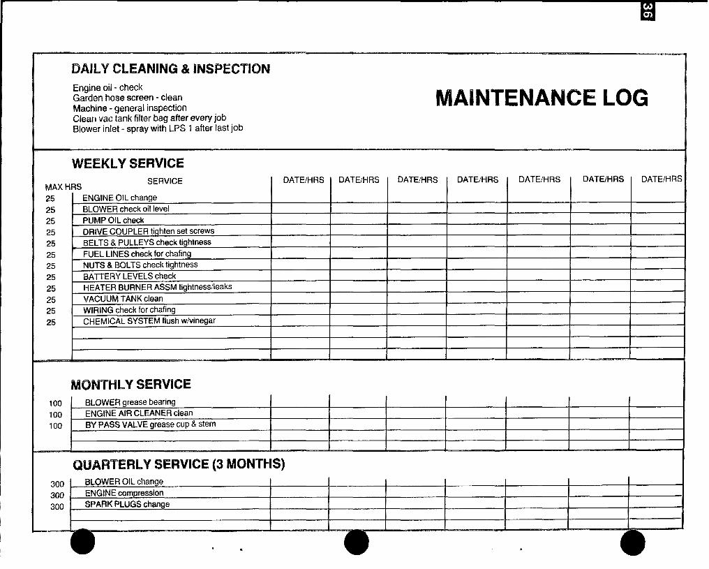
MAINTENANCE LOG
DAILY CLEANING & INSPECTION
Engine oil - checkGarden hose screen - cleanMachine - general inspectionClean wc tank filter bag after every jobBlower inlet - spray with U% 1 after last job
WEEKLY SERVICESERVICE
IDATWHRS I DATE/HRS IDATE/HRS
MAX HRS IDATE/EIRS
IDATE/HRS
IDATE/HRS
IDATE/i-lflS
25
25
25
25
25
2525
25
25
2525
25
I ENGINE OIL change I I IBLOWER check oil level I I
I PUMP OIL check‘m’”= COUPLER tighten set screws
& PULLEYS check tightness
l#W3 check for chafing
,.-, - .i BOLTS check tightness
BAITERY LEVELS check
I-BEATERBURNER ASSfvltightness/leaksVACUUM TANK cleanWIRING check for chafing
CHEMICAL SYSTEM flush w/vinegar
MONTHLY SEFWKX!100100
100
BLOWER grease bearingENGINE AIR CLEANER cleanBYPASS VALVE grease cup &.stem
11 I I I
QUARTERLY SERVICE (3 MONTHS)
300 SLOWER OIL change I 1
300 ENGINE impression
300 SPARK PLUGS change I I
1I I
.‘e


![I WIII MMWWWW| · United States Patent [19] Leeet al. I USOOS6 WIII MMWWWW| 33793A [11] Patent Number: 5,633,793 [45] Date ofPatent: May27, 1997 [54] SOFTSWIICHEDTHREE-PHASEBOOST](https://img.pdfslide.us/doc/110x75/5f08172e7e708231d42049b6/i-wiii-mmwwww-united-states-patent-19-leeet-al-i-usoos6-wiii-mmwwww-33793a.jpg)


![[Endeavor Silver]](https://img.pdfslide.us/doc/110x75/55cf8dfe550346703b8d6ced/endeavor-silver.jpg)