Embed Size (px)
Citation preview

1
WORK SAMPLESBO ZHAO

2 3
01. CULTURE CENTER IN NAGASAKI
THE GROUND FLOOR THE SECOND FLOOR THE THIRD FLOOR
TRAFFIC STREAMLINE ANALYSISB-B SECTION PLAN
The site in Nagasaki around the bay area next to the water and Kengo Kuma’s Nagasaki Prefectural Museum. With its excellent location and good accessibility, the site also well exposed and visible from a large part of the city and across the bay. However, beyond the significance or symbolic role of this large complex’s outside appearance, the internal arrangement and the impressive quality of all its public areas, or the interiors, are equally important. The relationship between outside and inside spaces is one of the critical aspects of the design. This also means that the shaping of outdoor places, a park, plazas, etc, will be integral part of the work.
JAPANESE ELEMENTS DESIGN PROCESS
SITE ANALYSIS
4 5
02. CONVERTIBLE TENSEGRITY -DOME STRUCTURE
CONCEPT
120 degree
PARAMETERS
The structure has axis generating triangular and hexago-nal shape of patterns. The reason to design in triangular shape is that triangle is more stiff than rectangular shape
in terms of structural stability.
The 6 points in hexagonal pattern has 2 differnet height level: 3 high and 3 low points. This level differences help the structure build beautiful membrane which will work
as tension member.
Rectangular tensegrity
Hexagonal & triangular tensegrity
MODULE OF TRIANGULAR TENSEGRITY3 studs are suspended in tension members.
MODULE OF BOX TENSEGRITY4 struts are suspended in tension members. Discontinuous compression
members in the sea of continuous tension members.
Module
Module
Rectangular tensegrity by Rene Motro
MECHANISM
Flat phase Flat phase
Actuated phase Actuated phase
189 MM
434 MM
434 MM
189 MM
366
MM
452
MM 36
6 M
M
189 MM
434 MM
434
MM
189 MM
366
MM
452
MM
366
MM
SECTION DIAGRAM
PLAN
The ability to flex the fingers consists of a flexor muscles in the forearm and their tendons are inserted into the bones of the fingers. The bones on human’s fingers works as compression members such as steel or concrete, and tendons will be tension members like cables.
When brain commends arm muscle to pull tendon (cable) to move forefinger, the muscle pulls tendon (cable) and then forefinger bone (steel) move toward the direction the tendon pulls.
The structure has the same concept. It is called folding tensegrity.
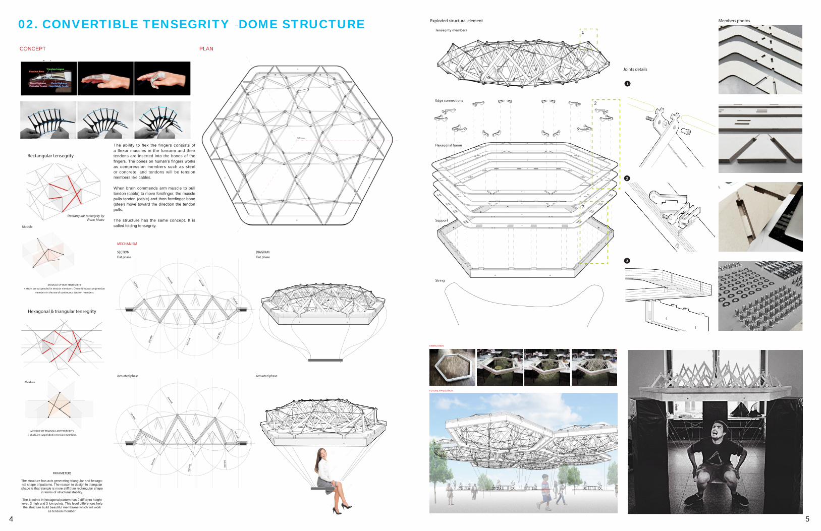
STRUCTURE AND JOINTS
Exploded structural element
Joints details
Members photos
Tensegrity members
Edge connections
Hexagonal frame
Support
String
1
2
3
1
2
3
FABRICATION
FUTURE APPLICATION

6 7
03. TOURISTS CENTER AT THE ANCIENT FERRY
Two axises based on main avenue and landscpe analysis.
Based on founction, seperating the site into two parts, one for public, and the ohter one for hotel.
Shaped by the surrouding environment, creating a new part for entrance space and connecting public and hotel space.
Refining the building details, such as skin and shape, specially the elevations. Make sure the new budling could in harmony with surrouding environment.
ROADS ANALYSIS
TRAFFIC ANALYSIS
PEDESTRIANS
MAIN ROADS
FOR PUBLICFOR BUILDING FOR INTERIOR
RECEPTION
INSIDE OUTSIDE PUBLIC
EXEHIBTION HOTEL
SECONDARY ROADS
PATHS
LANDSCAPE ANALYSIS
SPACE ANALYSIS
GREEN LANDANALYSIS
VEHICLES
1. Entrance2. Square3. Yard4. Garden5. Landscape Path6. Wharf A7.Wharf B8. Xianyang Lake9. Parking10. Public Landscape11. Nanping Rd.12.South Gate Building13. Weiyang West Rd.14. Residential Buidlings15. Commercial Buildings
THE GROUDN FLOOR THE SECOND FLOOR
THE THIRD FLOOR THE FOURTH FLOOR

8 9
04. CITY OASIS-GREEN DESIGN
SITE BOUNDARY RESIDENTIAL AREA ROAD SYSTEM
RESIDENTIAL PART COMMERCIAL PART
VENTILATION SYSTEM
DWELLING TYPES
SOLAR SYSTEM
CONCEPTS
TECHNOLOGIES
WATER SYSTEM
HOUSE COMBINATIONS

10 11
05. SLOW CITYHIGH-RISE RESIDENTIAL COMMERICAL BUILDING DESIGN
SITE ANALYSIS BLOCKS ANALYSIS
PLANS
GROUND FLOOR PLAN

12 13
06. AT&T CORPORATE CENTER CASE STUDY
BUILDING CONFIGURATION VERTICAL TRANSPORTATION
WIND LOADS CAISSON PLAN WATER RISER DIAGRAM AIR RISER DIAGRAM
16TH FLOOR MECHANICAL LEVEL TYPICAL FLOOR AIR DISTRIBUTION PLAN

14 15
07. DRAWINGS & SKETCHINGS 08. PHOTOGRAPHS