Embed Size (px)
Citation preview

1
“Bo” LArTPC Cryostat Piping System Engineering Note
Rev Date Description Originated by Approved by None June 24, 2008 Original issue T. Tope
Reviewed by: ________________________
Date: ______________________________
Fermilab

2
”Bo” LArTPC Cryostat
Piping System Engineering Note
Table of Contents
1.0 Introduction........................................................................................................3 2.0 Flow schematic...................................................................................................3 3.0 Design codes and evaluation criteria ...................................................................5 4.0 Materials ............................................................................................................5 5.0 Piping design and analysis ..................................................................................5 6.0 Pressure relief system .......................................................................................15 7.0 Welding and inspection ....................................................................................16 8.0 Pressure testing.................................................................................................16 9.0 Appendix..........................................................................................................17

3
“Bo” LArTPC Cryostat Piping System Engineering Note
1.0 Introduction This document constitutes the Piping System Engineering Note for the cryogenic
piping associated with the LArTPC cryostat known as “Bo” which is located inside the
Proton Assembly Building at Fermilab.
The cryogenic piping transports liquid argon to the cryostat for the purpose of
filling the cryostat with ultra-pure liquid argon. The pipe descriptions and a summary of
the operating parameters are shown in Table 1.1.
Table 1.1: Cryogenic piping description and summary
Description Fluid OD (in) ID (in) P oper (psid)
P max (psid)
T (approx)
“Bo” LAr supply line (vacuum jacketed)
GAr/LAr 0.500 0.430 250 400 87 K
“Bo” relief valve supply piping
GAr/LAr 1.90 1.682 10 35 87 K
“Bo” relief valve discharge vent piping
GAr/LAr 3.00 2.87 0 < 1 87 K
“Bo” cooldown/blowdown vent piping
GAr/LAr 0.500 0.430 < 15 < <350 87 K
2.0 Flow schematic
The relevant portion of the flow schematic for the cryostat is shown in Figure 2.1.
The complete flow schematic is available at http://lartpc-docdb.fnal.gov:8080/cgi-
bin/ShowDocument?docid=265 in Section 1.2.

4
Figure 2.1 Cryostat piping flow schematic.

5
3.0 Design codes and evaluation criteria
The “Bo” LArTPC cryostat piping must meet all of the requirements of Section
5031.1 of the Fermilab ES&H Manual. This section states that piping systems containing
cryogenic fluids fall under the category of Normal Fluid Service and shall adhere to the
requirements of the ASME Process Piping Code B31.3.
4.0 Materials
The piping is fabricated from 304/304L stainless steel tube and pipe. In addition
to 304/304L material, some of the components and flanges are 316/316L stainless steel.
The lowest allowable stress for both of these materials from Table A-1 of ASME B31.3
will be used in this analysis, which is 16,700 psi.
The LAr piping will be operated at 87 K. This is above the minimum temperature
listed for 304/316 stainless steel pipe or tube (19 K). According to Table 323.2.2 of the
Code, impact testing is not required for these austenitic stainless steels. However, Table
323.2.2 does require impact testing of the weld metal and heat affected zone except as
stated in Table 323.2.2 Note (6) where impact testing is not required when the minimum
obtainable Charpy specimen has a width along the notch of less than 2.5 mm (0.098 in).
All of the pipe or tube used in the “Bo” cryostat piping system has a manufacturer’s
minimum wall thickness less than 0.098 in. Therefore, impact testing is not required for
this piping system. It should also be noted the Fermilab has extensive service experience
using the 300 series stainless steels at liquid nitrogen temperatures.
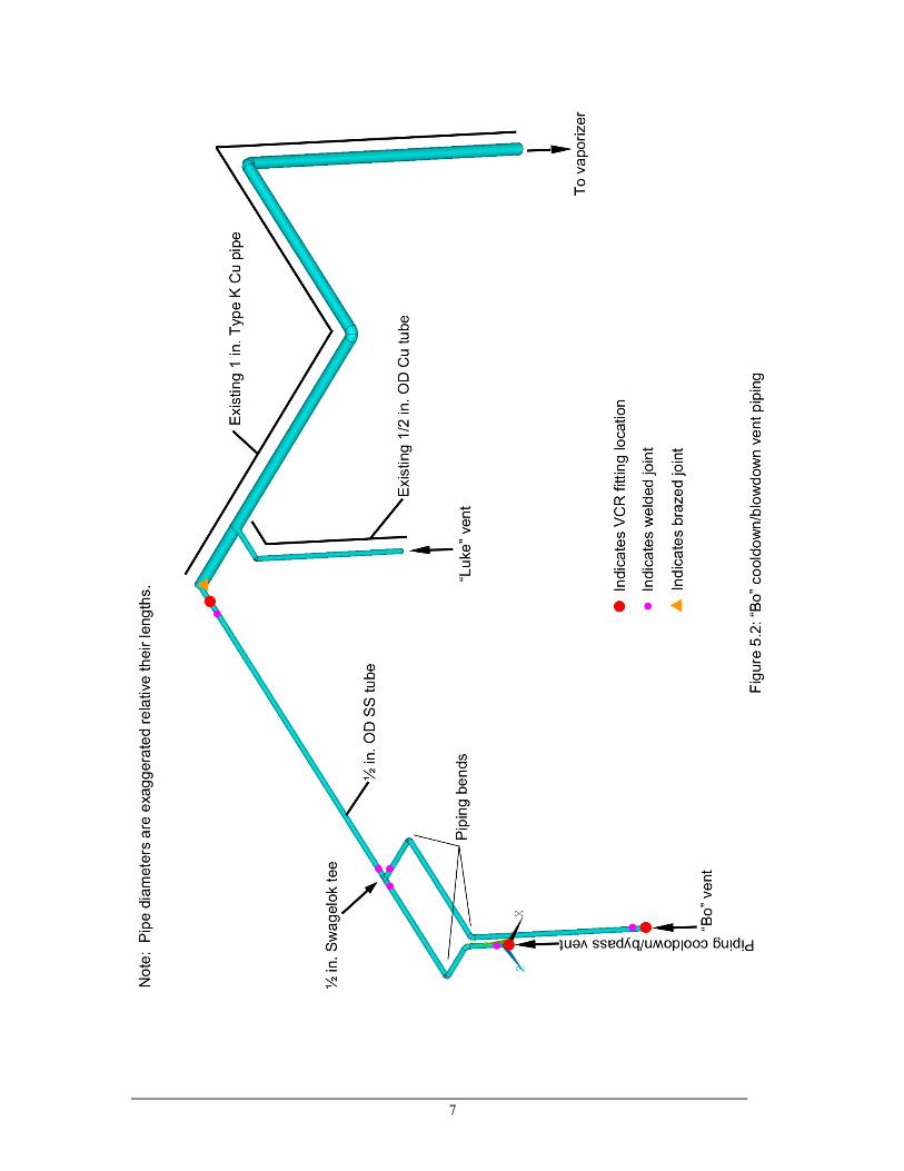
5.0 Piping design and analysis A schematic of the piping that supplies LAr to “Bo” is shown in Figure 5.1. The cooldown/bypass vent piping associated with “Bo” is shown in Figure 5.2.

6
7

8
The minimum thickness of the pipes is evaluated using the procedures in
304.1.2(a) of ASME B31.3. The minimum tube thickness for seamless or longitudinally
welded piping for t<D/6 is given by:
)(2 PYSEW
PDt
+=
where: t = wall thickness, (manufacturers minimum value is used)
P = internal design pressure
D = outside diameter (manufacturers nominal value is used)
S = allowable stress from table A-1
E = quality factor from table A-1A or A-1B = 0.8 (worst case)
W = weld joint strength reduction factor = 1
Y = coefficient from Table 304.1.1 = 0.4
Table 5.1 summarizes the results of the wall thickness calculation.
Table 5.1. Cryogenic piping parameters
Pipe / Tube P (psid)
D (in)
S (psi)
E t req’d (in)
t mfg min (in)
MAWP (psid)
LAr supply line (vacuum jacketed)
400a 0.500 16,700 0.8 0.00740 0.0315 1772
“Bo” relief valve supply piping
35b 1.900 16,700 0.8 0.00249 0.0954 1397
“Bo” relief valve discharge piping
< 1c 3 16,700 0.8 0.0001 0.0585 529
“Bo” cooldown/blowdown vent piping
<< 350d 0.500 16,700 0.8 0.0065 0.0315 1772
(a) Pressure limited by trapped volume relief valve (PSV-250-Ar).
(b) Pressure limited by cryostat ASME relief valve (PSV-377-Ar).
(c) Relief valve calculations estimate vent pressure drop as less than 1 psi
(http://lartpc-docdb.fnal.gov:8080/cgi-bin/ShowDocument?docid=265, Section
4.1a).
(d) Supply dewer reliefs are set at 350 psig. The pressure in the cooldown/blowdown
vent pipe during system cooldown (when the crysotat is bypassed) will be much
less than 350 psig because 98% of the flow resistance is upstream of the vent
pipe. The resistance coefficient for the supply piping up to the
9
cooldown/blowdown vent piping is 340.9 while the resistance coefficient for the
vent piping is only 4.3 (all piping converted to a common reference diameter).
In the above four cases the manufacturer’s minimum wall thickness of the piping
is greater than the minimum thickness required by ASME B31.3.
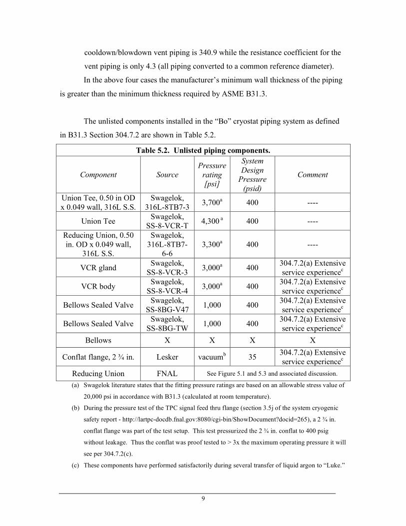
The unlisted components installed in the “Bo” cryostat piping system as defined
in B31.3 Section 304.7.2 are shown in Table 5.2.
Table 5.2. Unlisted piping components.
Component Source Pressure
rating [psi]
System Design
Pressure (psid)
Comment
Union Tee, 0.50 in OD x 0.049 wall, 316L S.S.
Swagelok, 316L-8TB7-3 3,700a 400 ----
Union Tee Swagelok, SS-8-VCR-T 4,300 a 400 ----
Reducing Union, 0.50 in. OD x 0.049 wall,
316L S.S.
Swagelok, 316L-8TB7-
6-6 3,300a 400 ----
VCR gland Swagelok, SS-8-VCR-3 3,000a 400 304.7.2(a) Extensive
service experiencec
VCR body Swagelok, SS-8-VCR-4 3,000a 400 304.7.2(a) Extensive
service experiencec
Bellows Sealed Valve Swagelok, SS-8BG-V47 1,000 400 304.7.2(a) Extensive
service experiencec
Bellows Sealed Valve Swagelok, SS-8BG-TW 1,000 400 304.7.2(a) Extensive
service experiencec Bellows X X X X
Conflat flange, 2 ¾ in. Lesker vacuumb 35 304.7.2(a) Extensive service experiencec
Reducing Union FNAL See Figure 5.1 and 5.3 and associated discussion.
(a) Swagelok literature states that the fitting pressure ratings are based on an allowable stress value of
20,000 psi in accordance with B31.3 (calculated at room temperature).
(b) During the pressure test of the TPC signal feed thru flange (section 3.5j of the system cryogenic
safety report - http://lartpc-docdb.fnal.gov:8080/cgi-bin/ShowDocument?docid=265), a 2 ¾ in.
conflat flange was part of the test setup. This test pressurized the 2 ¾ in. conflat to 400 psig
without leakage. Thus the conflat was proof tested to > 3x the maximum operating pressure it will
see per 304.7.2(c).
(c) These components have performed satisfactorily during several transfer of liquid argon to “Luke.”

10
The piping bends are analyzed based on 304.2.1 of the Code. The minimum
required thickness is given by:
))/((2 PYISEW
PDt
+=
where: t = wall thickness
P = internal design pressure, 400 psid
D = outside diameter, 0.50 in.
S = allowable stress from table A-1, 16,700 psi for 304 S.S.
E = quality factor from table A-1A or A-1B = 0.8 (worst case)
W = weld joint strength reduction factor = 1
Y = coefficient from Table 304.1.1 = 0.4
I = factor for location in pipe bend: intrados, extrados and centerline
The following equations are used to determine I at the three locations:
at the intrados: 2)/(4
1)/(4
1
1
!
!=
DR
DRI
at the extrados: 2)/(4
1)/(4
1
1
+
+=
DR
DRI
at the centerline: I = 1.0 R1 = bend radius of the tubing, 5.0 in. The results are as follows: t(in) at intrados = 0.00760; extrados = 0.00722; centerline =
0.00740 (same as straight tube).
The bent tubing has a minimum wall thickness of 0.0315 inches so this requirement is satisfied.
The transition between the ½ inch SS 316L tee and the 3/8 in. OD Cu tube was fabricated
from a Swagelok VCR tee (SS-8-VCR-T) as shown in Figure 5.3. Two sides of the tee
are used to make up VCR joints that feed “Luke” and “Bo.” The third side of the tee had
the VCR threads cut off and has a copper line brazed into it. Because the inside diameter
of the tee is larger than the 3/8 in Cu tube OD, a Cu spacer was machined to create a tight

11
fit for brazing. The joint was brazed by Cary Kendziora using XUPER 1020 XFC silver
brazing alloy which has a tensile strength of 85 ksi (data sheet included in the appendix).
The flexibility of the LAr supply piping was analyzed using ANSYS. The model boundary conditions and results are summarized in Figures 5.4 and 5.5. The thermal shrinkage was taken to be 290 x 10-5 ΔL/L for 304 Stainless and 314 x 10-5 ΔL/L for Cu tube. The modulus of elasticity of 304 Stainless was input as 2.07E11 Pa along with a Poisson’s Ratio of 0.28. The modulus of elasticity of Cu was input as 1.207E11 Pa along with a Poisson’s Ratio of 0.35. The model also considers the density of the contained fluid, which was input as 1400 kg/m3 for argon. The model is comprised of ANSYS PIPE 16 (straight), PIPE 17 (tee), and PIPE 18 (elbow) elements in which ANSYS calculates flexibility and stress intensification per B31.1. The stress intensification factors for B31.3 are the same as for B31.1. The model contour plot shows a peak Von Mises stress of 2,161 psi where the ½ inch OD stainless steel tube discharges into Bo. Per B31.3 Appendix P, the operating stress is computed using equation (P17a)
!
So
= Sa
+ Sb( )2
+ 4St
2 where the axial (Sa), bending (Sb), and torsional (St) stresses are combined and compared to the allowable stress SoA in para. P302.3.5(d) where
Brazed joint
3/8 in. OD Cu tube
Machined Cu tube spacer to create tight fit
Flow to “Bo”
Flow to “Luke” Flow from O2 filter
0.375 in.
Figure 5.3: Brazed joint details
12
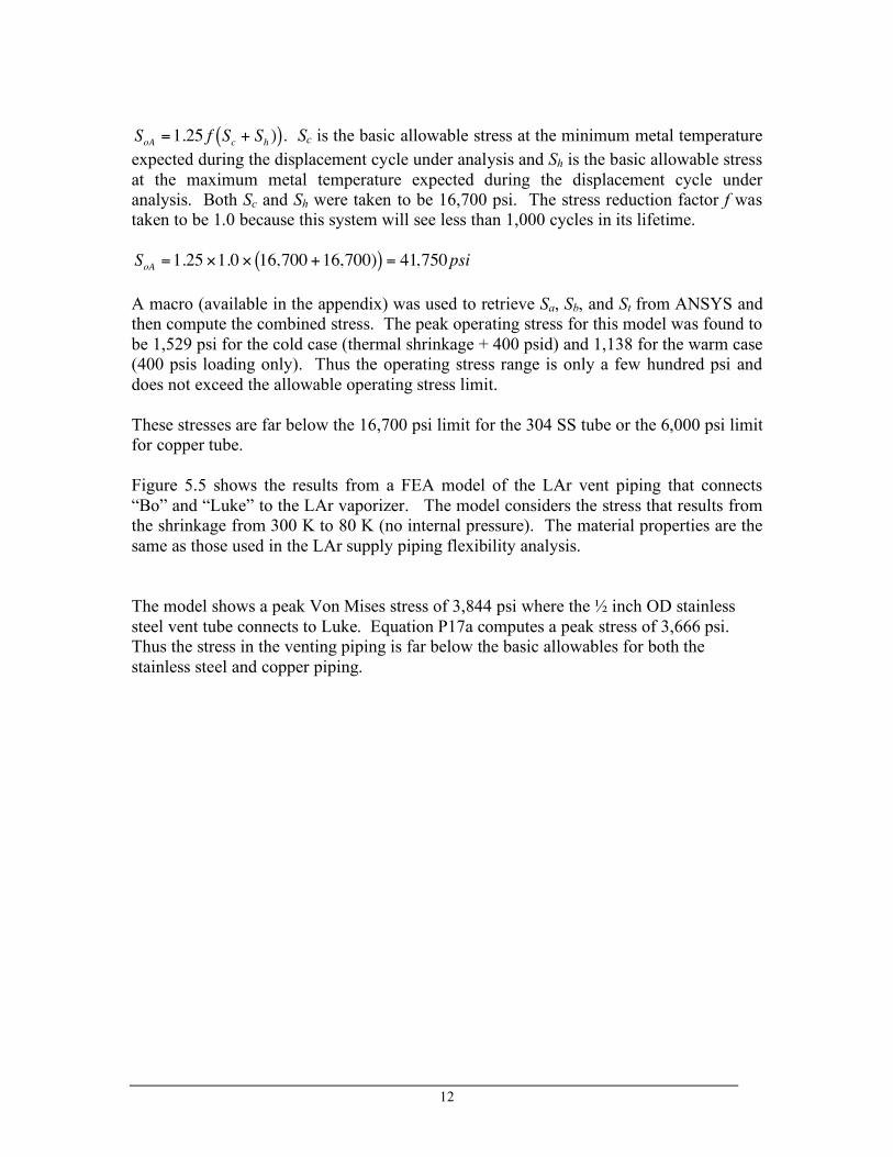
!
SoA =1.25 f Sc + Sh )( ). Sc is the basic allowable stress at the minimum metal temperature expected during the displacement cycle under analysis and Sh is the basic allowable stress at the maximum metal temperature expected during the displacement cycle under analysis. Both Sc and Sh were taken to be 16,700 psi. The stress reduction factor f was taken to be 1.0 because this system will see less than 1,000 cycles in its lifetime.
!
SoA =1.25 "1.0 " 16,700 +16,700)( ) = 41,750psi A macro (available in the appendix) was used to retrieve Sa, Sb, and St from ANSYS and then compute the combined stress. The peak operating stress for this model was found to be 1,529 psi for the cold case (thermal shrinkage + 400 psid) and 1,138 for the warm case (400 psis loading only). Thus the operating stress range is only a few hundred psi and does not exceed the allowable operating stress limit. These stresses are far below the 16,700 psi limit for the 304 SS tube or the 6,000 psi limit for copper tube. Figure 5.5 shows the results from a FEA model of the LAr vent piping that connects “Bo” and “Luke” to the LAr vaporizer. The model considers the stress that results from the shrinkage from 300 K to 80 K (no internal pressure). The material properties are the same as those used in the LAr supply piping flexibility analysis. The model shows a peak Von Mises stress of 3,844 psi where the ½ inch OD stainless steel vent tube connects to Luke. Equation P17a computes a peak stress of 3,666 psi. Thus the stress in the venting piping is far below the basic allowables for both the stainless steel and copper piping.

13
Fixed to bottom of O2 filter
Liquid discharge fixed to piping vacuum jacket in Luke
Liquid discharge fixed to piping vacuum jacket in Bo
This end free in model due to bellows between inner pipe and vacuum jacket
3/8 in. OD Cu tube
3/8 in. OD SS tube
1/2 in. OD SS tube
Figure 5.4: LAr supply piping Von Mises Stresses due to cooldown shrinkage and internal 400 psig pressure.
(2,161 psi) (1,355 psi)
N/m2
LAr flow direction

14
Fixed to LAr vent piping vacuum jacket
Fixed to LAr vaporizer inlet
Figure 5.5: LAr vent piping Von Mises Stresses due to cooldown shrinkage.
(3,844 psi) (19 psi)
N/m2
Fixed to Bo top flange
Fixed to Luke top flange
1/2 in. OD SS tube
1 in. Type K Cu
Hanger fixes pipe in all directions except for Z
Hanger fixes pipe in all directions except for X
Z X
Y
15
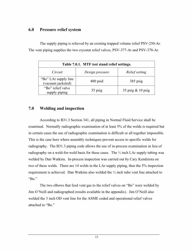
6.0 Pressure relief system
The supply piping is relieved by an existing trapped volume relief PSV-250-Ar.
The vent piping supplies the two cryostat relief valves, PSV-377-Ar and PSV-378-Ar.
Table 7.0.1. MTF test stand relief settings.
Circuit Design pressure Relief setting
“Bo” LAr supply line (vacuum jacketed) 400 psid 385 psig
“Bo” relief valve supply piping 35 psig 35 psig & 10 psig
7.0 Welding and inspection According to B31.3 Section 341, all piping in Normal Fluid Service shall be
examined. Normally radiographic examination of at least 5% of the welds is required but
in certain cases the use of radiographic examination is difficult or all together impossible.
This is the case here where assembly techniques prevent access to specific welds for
radiography. The B31.3 piping code allows the use of in-process examination in lieu of
radiography on a weld-for-weld basis for these cases. The ½ inch LAr supply tubing was
welded by Dan Watkins. In-process inspection was carried out by Cary Kendziora on
two of these welds. There are 14 welds in the LAr supply piping, thus the 5% inspection
requirement is achieved. Dan Watkins also welded the ½ inch tube vent line attached to
“Bo.”
The two elbows that feed vent gas to the relief valves on “Bo” were welded by
Jim O’Neill and radiographed (results available in the appendix). Jim O’Neill also
welded the 3 inch OD vent line for the ASME coded and operational relief valves
attached to “Bo.”
16
8.0 Pressure testing
The piping system was pressure tested in accordance with Section 5034 of the
Fermilab ES&H Manual and 345.5 of the Code. The test pressure is 110% of the design
pressure. The test pressures was as follows:
• LAr circuit: 440 psig (while the vacuum jacket was evacuated an
monitored. (See section 3.5k http://lartpc-docdb.fnal.gov:8080/cgi-
bin/ShowDocument?docid=265).
• Relief valve supply piping: Will be tested to 38.5 psig.
The test medium was gaseous argon.

17
9.0 Appendix
Figure A.1: “Bo” relief valve supply elbows.
Butt welds radiographed

18
Figure A.2: Radiography results. Weld W-3 is a weld that is part of a different piping
system that is not associated with “Bo.”

19
Figure A-3: ANSYS macro used to compute operating stress.

20
Figure A-4: Dan Watkin’s welding qualification for stainless steel.

21
Figure A-5: Jame’s O’Neal’s welding qualifications for stainless steel.