Embed Size (px)
Citation preview

BNI IOL-802-102-Z036
BNI IOL-802-102-Z037
Smart Light
User’s Guide

www.balluff.com 1
Content
1 Notes to the user 3 1.1 About this guide 3 1.2 Structure of the guide 3 1.3 Typographical conventions 3
Enumerations 3 Actions 3 Syntax 3 Cross-references 3
1.4 Symbols 3 1.5 Abbreviations 3
2 Safety 4 2.1 Intended use 4 2.2 Installation and startup 4 2.3 General safety instructions 4
Hazardous voltage 4
3 Getting Started 5 3.1 Overview BNI IOL-802-102-Z036 5 3.2 Overview BNI IOL-802-102-Z037 6 3.3 Mechanical connection 7 3.4 Electrical connection 7 3.5 Function ground 7 3.6 IO-Link connection 7
Smart Light connection 7 Module versions 7
3.7 Short description of the functionality 8 3.8 Segment mode 8 3.9 Level mode 8 3.10 Runlight mode 11
4 IO-Link Interface 12 4.1 IO-Link Data 12 4.2 Process data / Input data 12
BNI IOL-802-102-Z03x 12 Error codes 12
4.3 Process data / Output data 12 BNI IOL-802-102-Z03x, Segment Mode 13 BNI IOL-802-102-Z03x, Level Mode 16 BNI IOL-802-102-Z03x, Runlight Mode 19
4.4 Parameter data/ Request data 22 Level resolution 43hex 24 Level mode limit x-y 49hex 4Ahex 4Bhex 4Chex 24 Supply monitoring 50hex 25 Brightness 51hex 25 User color FChex 25 Limit type FDhex 26 Buzzer type FEhex 26
4.5 Errors 26 4.6 Events 26
5 Technical Data 27 5.1 Dimensions 27 5.2 Mechanical data 27 5.3 Electrical data 27 5.4 Operating conditions 27 5.5 LED indicator 28
Status LED 28
6 Appendix 29

Balluff / IO-Link BNI IOL-802-102-Z03x
www.balluff.com 2
6.1 Product ordering code 29 6.2 Order information 29
Included material 29

www.balluff.com 3
1 Notes to the user
1.1 About this guide This guide describes the Balluff BNI IOL-802-102-Z03x for the application as status light module. Hereby it is about an IO-Link device which communicates by means of IO-Link protocol with the superordinate IO-Link master assembly.
1.2 Structure of the
guide The guide is organized so that the sections build on one another.
Section 2: Basic safety information.
Section 3: The main steps for installing the device. Section 4: IO-Link, parameter and process data for the device. Section 5: Technical data for the device.
1.3 Typographical
conventions The following typographical conventions are used in this Guide.
Enumerations Enumerations are shown in list form with bullet points.
• Entry 1, • Entry 2.
Actions Action instructions are indicated by a preceding triangle. The result of an action is indicated
by an arrow. Action instruction 1. Action result. Action instruction 2.
Syntax Numbers:
Decimal numbers are shown without additional indicators (e.g. 123), Hexadecimal numbers are shown with the additional indicator hex (e.g. 00hex).
Cross-references Cross-references indicate where additional information on the topic can be found (see
Section 5 -"Technical Data“).
1.4 Symbols Note! This symbol indicates a security notice which must be observed.
Note, tip This symbol indicates general notes.
1.5 Abbreviations BNI
DPP EMC FE IOL ISDU
Balluff Networking Interface Direct Parameter Page Electromagnetic Compatibility Function Earth IO-Link Indexed Service Data Unit

Balluff / IO-Link BNI IOL-802-102-Z03x
www.balluff.com 4
2 Safety
2.1 Intended use
This guide describes the Balluff BNI IOL-802-102-Z03x for the application as status light module. Hereby it is about an IO-Link device which communicates by means of IO-Link protocol with the superordinate IO-Link master assembly.
2.2 Installation and
startup Note
Installation and startup are to be performed only by trained specialists. Qualified personnel are persons who are familiar with the installation and operation of the product, and who fulfills the qualifications required for this activity. Any damage resulting from unauthorized manipulation or improper use voids the manufacturer's guarantee and warranty. The Operator is responsible for ensuring that applicable of safety and accident prevention regulations are complied with.
2.3 General safety
instructions Commissioning and inspection
Before commissioning, carefully read the operating manual. The system must not be used in applications in which the safety of persons is dependent on the function of the device. Authorized Personnel Installation and commissioning may only be performed by trained specialist personnel. Intended use Warranty and liability claims against the manufacturer are rendered void by:
Unauthorized tampering
Improper use
Use, installation or handling contrary to the instructions provided in this operating
manual Obligations of the Operating Company The device is a piece of equipment from EMC Class A. Such equipment may generate RF noise. The operator must take appropriate precautionary measures. The device may only be
used with an approved power supply. Only approved cables may be used. Malfunctions In the event of defects and device malfunctions that cannot be rectified, the device must be taken out of operation and protected against unauthorized use. Intended use is ensured only when the housing is fully installed.
Hazardous voltage
Note Disconnect all power before servicing equipment.
Note In the interest of product improvement, the Balluff GmbH reserves the right to change the specifications of the product and the contents of this manual at any time without notice.

www.balluff.com 5
3 Getting Started
3.1 Overview BNI IOL-802-102-Z036
Fig. 3-1: BNI IOL-802-102-Z036 1 Cap
2 Segment 1 3 Segment 2 4 Segment 3 5 Segment 4
6 Segment 5
7 Socket 8 M12 connector 9 M18 thread for mounting 10 Status LED
8
10
6
7
9
5
4
3
2
1
Balluff / IO-Link BNI IOL-802-102-Z03x
www.balluff.com 6
3 Getting Started
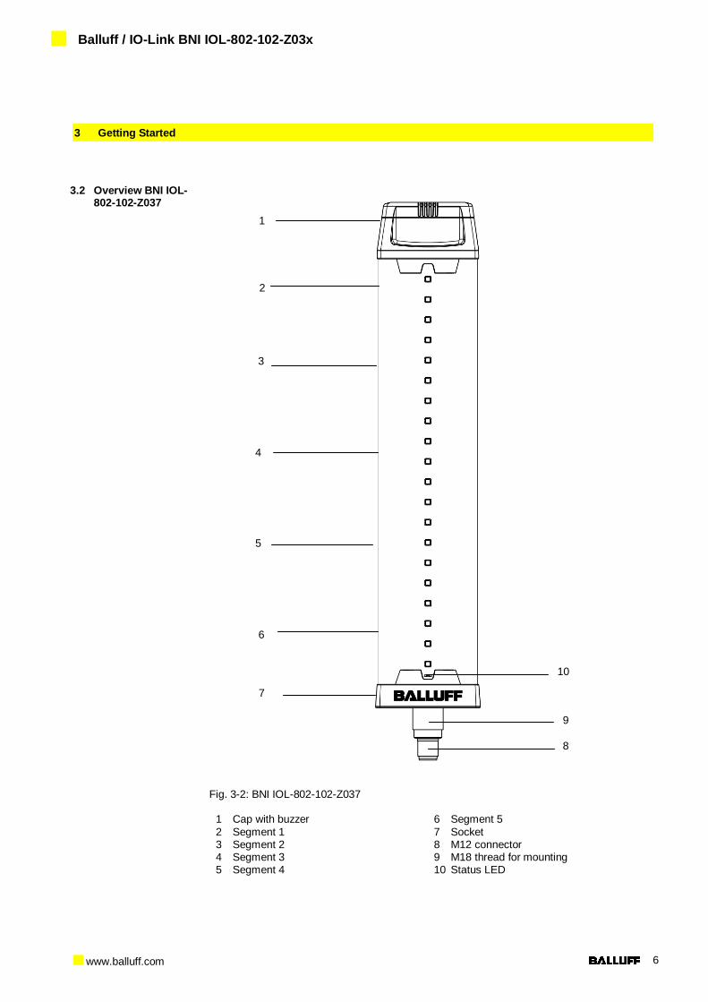
3.2 Overview BNI IOL-802-102-Z037
Fig. 3-2: BNI IOL-802-102-Z037 1 Cap with buzzer
2 Segment 1 3 Segment 2 4 Segment 3 5 Segment 4
6 Segment 5
7 Socket 8 M12 connector 9 M18 thread for mounting 10 Status LED
8
10
6
7
9
5
4
3
2
1
www.balluff.com 7
3 Getting Started
3.3 Mechanical connection
The BNI IOL-802-102-Z03x modules are attached by using an M18 nut.
3.4 Electrical
connection The BNI IOL-802-102-Z03x modules require no separate supply voltage connection. Power
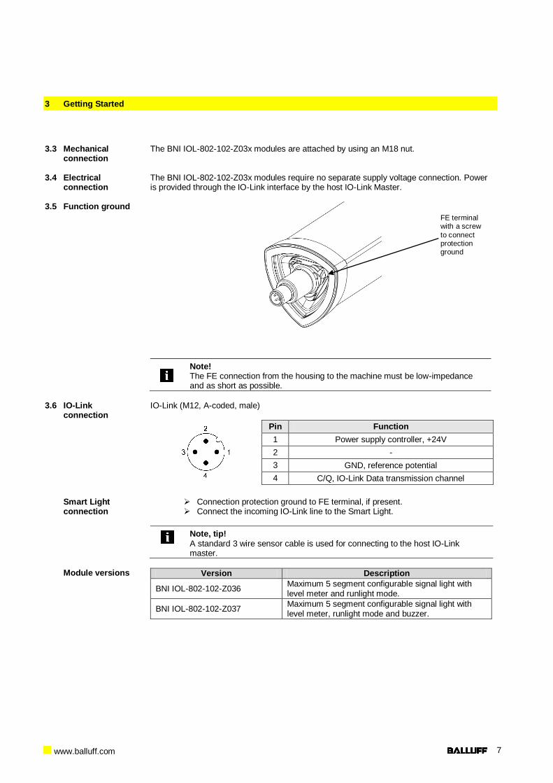
is provided through the IO-Link interface by the host IO-Link Master. 3.5 Function ground
Note! The FE connection from the housing to the machine must be low-impedance and as short as possible.
3.6 IO-Link
connection
IO-Link (M12, A-coded, male)
Pin Function
1 Power supply controller, +24V
2 -
3 GND, reference potential
4 C/Q, IO-Link Data transmission channel
Smart Light
connection
Connection protection ground to FE terminal, if present. Connect the incoming IO-Link line to the Smart Light.
Note, tip! A standard 3 wire sensor cable is used for connecting to the host IO-Link master.
Module versions Version Description
BNI IOL-802-102-Z036 Maximum 5 segment configurable signal light with level meter and runlight mode.
BNI IOL-802-102-Z037 Maximum 5 segment configurable signal light with level meter, runlight mode and buzzer.
FE terminal with a screw
to connect protection ground

Balluff / IO-Link BNI IOL-802-102-Z03x
www.balluff.com 8
3 Getting Started
3.7 Short description of the functionality
The functionality of the Balluff status light module can be controlled through process data and ISDU registers. It has three main mode of functionality:
Segment mode
Level mode
Runlight mode With the help of these three modus various warning and indication signals can be indicated. The buzzer function is available in all modes.
3.8 Segment mode To use the module as a standard status light, the corresponding byte (Mode select) must be
written with the proper value in the process data. The process data controls the color of each segment. In the segment mode the module can be used as a standard status light, with configurable number of segments. Maximum five segments can be set. Irrespectively of the selected number of segments, always all of the LEDs are used as a display element. The number of the segments can be set any number between 1 and 5. The module has 20 LEDs, which are equally distributed between the segments. (When three segments are set, one-one LEDs between the segments will be always switched off). The color of each segment can be selected from a color table, which has six pre-defined colors and one user defined color. The combinations of the pre-defined colors are not limited. In the segment mode, the segments can be set to blink too. Each segment has two control bits in process data, which determine the blinking state of the corresponding segment and the type of the blinking. The blinking has two modus. Either normal blinking or flash mode can be selected. In normal blinking the LEDs are switched on and off periodically with a 50% duty cycle. In the flash mode, the LEDs are switched on and off quickly three times. The flash is repeated in every second. The frequency of the normal blinking can be changed too.
3.9 Level mode To use the module as a standard status light, the corresponding byte (Mode select) must be
written with the proper value in the process data. In level mode the complete module works as one indicator element. In this case a level value can be displayed. The input process data gives the level value. The higher value the module becomes, the more LEDs will be switched on. This mode can be used as a level indicator, for example to indicate a fluid level in a tank. The resolution of the input level can be selected from 8 bit up to 16 bit. In the level mode various parameters can be controlled through the process data or ISDU registers. The ISDU parameters should be set before the level mode is used. The level display can be selected to be bottom-up or top-down. In the bottom-up mode the level indicator increases from the bottom of the module. In the top-down mode the indicator increases from the top of the module. Although there are no real segments in the level mode, because the LEDs are controlled by the input level, the LEDs are divided into five virtual segments. These virtual segments can have their own color. The color of these segments can be set in the process data. So it can be realized, that the level meter can have more colors (up to the maximum number of the segments). Some or all colors can be set as dominant color. This means, when the input level is high enough to switch on the next LED and this LED is in another virtual segment, the LEDs, which are under the actual LED, take over the color of the actual LED. In this case, as the input level increases, the color of the full LED bar can be changed. For example: The lower two segments are green, the middle two segments are yellow and the upper segment is red. The LEDs are shown in the next figures, when the Smartlight level mode is configured differently.

www.balluff.com 9
3 Getting Started
The LED bar at increasing input data and no color dominance. (The virtual segments can be seen on the left side.) Of course the segment 2 or 4 does not have to be the same color as segment 3 or 5.
Seg. 1
Seg. 2
Seg. 3
Seg. 4
Seg. 5

Balluff / IO-Link BNI IOL-802-102-Z03x
www.balluff.com 10
3 Getting Started
The LED bar at increasing input data, all the colors are dominant.
Seg. 1
Seg. 2
Seg. 3
Seg. 4
Seg. 5

www.balluff.com 11
3 Getting Started
By default the 20 LEDs are divided into equal virtual segments. The height of the virtual segments can be modified too. There are four ISDU registers (Level mode limit x-y ISDU register), in which the limits of the virtual segments can be modified. For example: If the input level value is higher than the limit value of the 2. and 3. segment (Level mode limit 2-3), the current LED will become the color of the Level mode segment 2 color. The limits can be given either in percent or in absolute value.
The LED bar at increasing input data, there is no color dominance. The limits of the
segments are modified, so they are not equally distributed. Of course segment 3, 4 and 5 could have different colors too.
Seg. 1
Seg. 2
Seg. 3
Seg. 4
Seg. 5
3.10 Runlight mode To use the module as a standard status light, the corresponding byte (Mode select) must be
written with the proper value in the process data. In the runlight mode, the complete module displays a running light effect. In this case all of the LEDs are working as one runlight effect. The process data defines the color of the running segment, the background color, the size of the running segment and the speed of the segment. One segment has a size of 4 LEDs. The number of the running segment can be set between 1 and 3.

Balluff / IO-Link BNI IOL-802-102-Z03x
www.balluff.com 12
4 IO-Link Interface
4.1 IO-Link Data BNI IOL-802-102-Z036, BNI IOL-802-102-Z037
Data transmission rate COM2 (38,4 kBaud)
Minimal cycle time 7.2 ms
Process data length 8 Byte output, 1 Byte input
IO-Link Revision 1.1 1.0
Frame type 2.V 1
Process data cycle time* 7.2 ms 72 ms
* by min. cycle time
4.2 Process data / Input data
The BNI IOL-802-102-Z03x has one byte input process data. The input process data contains the error value for configuration errors. There are different errors, which can be present at the same time, but only the error code with the highest priority will be send in the input process data.
BNI IOL-802-102-Z03x
Byte 0
Bit 7 6 5 4 3 2 1 0
Des
cri
pti
on
Error code
Error codes 0x00 – No error 0x01 – Wrong mode selected 0x02 – Level value out of range 0x04 – Wrong number of segments selected 0x05 – Wrong frequency selected 0x06 – Wrong speed selected 0x07 – Wrong buzzer function selected (Only in case of BNI IOL-802-102-Z037) An error code (values from 0x01 to 0x07) with lower value has higher priority than error code with higher value.
4.3 Process data / Output data
The BNI IOL-801-102-Z03x has 8 byte output process data. The output process data has different meaning depending on the selected mode (segment mode, level mode or runlight mode). The byte 3 has a special meaning in the output process data. It is common for all modes. The mode of the Smart Light can be selected with the help of this byte.

www.balluff.com 13
4 IO-Link Interface
BNI IOL-802-102-
Z03x, Segment Mode
Byte 0
Bit 7 6 5 4 3 2 1 0
Des
cri
pti
on
Segm
ent
2 b
link
Segm
ent
2
colo
r
Segm
ent
1 b
link
Segm
ent
1
colo
r
Byte 1
Bit 7 6 5 4 3 2 1 0
Des
cri
pti
on
Segm
ent
4 b
link
Segm
ent
4
colo
r
Segm
ent
3 b
link
Segm
ent
3
colo
r
Byte 2
Bit 7 6 5 4 3 2 1 0
Des
cri
pti
on
Buzzer
sta
te
-
Buzzer
Type
Segm
ent
5 b
link
Segm
ent
5
colo
r
Bit 0-2/4-6, Segment color
000 = Off 001 = Green 010 = Red 011 = Yellow 100 = Blue 101 = Orange 110 = User defined 111 = White Bit 3, Segment blink 0 – Segment does not blink 1 – Segment blinks according to the blink modus settings
Bit 4-5, Buzzer type (Only in case of BNI IOL-802-102-Z037) 00 = Continuous sound 01 = 1 Hz chopped sound 10 = 5 Hz chopped sound 11 = 3 short beep, 2 sec pause Bit 7, Buzzer state (Only in case of BNI IOL-802-102-Z037) 0 – Buzzer is off 1 – Buzzer is on

Balluff / IO-Link BNI IOL-802-102-Z03x
www.balluff.com 14
4 IO-Link Interface
Byte 3
Bit 7 6 5 4 3 2 1 0
Des
cri
pti
on
- - - - -
Run
light
Mod
e
Levle
Mo
de
Segm
ent
Mod
e
The operating mode of the Smart Light can be selected in the Byte 3. Only one bit should be
set at the same time.
Byte 4
Bit 7 6 5 4 3 2 1 0
Des
cri
pti
on
Number of segments (1 – 5)
Byte 5
Bit 7 6 5 4 3 2 1 0
Des
cri
pti
on
- - -
Blin
k m
od
e S
egm
en
t 5
Blin
k m
od
e S
egm
en
t 4
Blin
k m
od
e S
egm
en
t 3
Blin
k m
od
e S
egm
en
t 2
Blin
k m
od
e S
egm
en
t 1
Blink mode segment X
0 – The segment is blinking with a 50% duty cycle 1 – The segment is flashing.

www.balluff.com 15
4 IO-Link Interface
Byte 6
Bit 7 6 5 4 3 2 1 0 D
es
cri
pti
on
Blinking frequency (1 – 5)
0x01 – 0.5 Hz
0x02 – 1 Hz 0x03 – 2 Hz 0x04 – 5 Hz 0x05 – 10 Hz
Byte 7
Bit 7 6 5 4 3 2 1 0
Des
cri
pti
on
Reserved

Balluff / IO-Link BNI IOL-802-102-Z03x
www.balluff.com 16
4 IO-Link Interface
BNI IOL-802-102-Z03x, Level Mode
Byte 0
Bit 7 6 5 4 3 2 1 0
Des
cri
pti
on
Segm
ent
2
dom
ina
nce
Segm
ent
2
colo
r
Segm
ent
1
dom
ina
nce
Segm
ent
1
colo
r
Byte 1
Bit 7 6 5 4 3 2 1 0
Des
cri
pti
on
Segm
ent
4
dom
ina
nce
Segm
ent
4
colo
r
Segm
ent
3
dom
ina
nce
Segm
ent
3
colo
r
Byte 2
Bit 7 6 5 4 3 2 1 0
Des
cri
pti
on
Buzzer
sta
te
-
Buzzer
Type
Segm
ent
5
dom
ina
nce
Segm
ent
5
colo
r
Bit 0-2/4-6, Segment color
000 = Off 001 = Green 010 = Red 011 = Yellow 100 = Blue 101 = Orange 110 = User defined 111 = White Bit 3 / 7, Segment dominance 0 – Segment is not dominant 1 – Segment is dominant
Bit 4-5, Buzzer type (only by BNI IOL-802-102-Z037) 00 = Continuous sound 01 = 1 HZ chopped sound 10 = 5 Hz chopped sound 11 = 3 short beep, 2 sec pause Bit 7, Buzzer state (only by BNI IOL-802-102-Z037) 0 – Buzzer is off 1 – Buzzer is on

www.balluff.com 17
4 IO-Link Interface
Byte 3
Bit 7 6 5 4 3 2 1 0 D
es
cri
pti
on
- - - - -
Run
light
Mod
e
Levle
Mo
de
Segm
ent
Mod
e
The operating mode of the Smart Light can be selected in the Byte 3. Only one bit should be
set at the same time. The Smart Light will be switched off, when the operating mode is set to 0x00.
Byte 4
Bit 7 6 5 4 3 2 1 0
Des
cri
pti
on
- - - - - - -
Leve
l ty
pe
0 – bottom – up
1 – top - down
Byte 5
Bit 7 6 5 4 3 2 1 0
Des
cri
pti
on
Level value (16 bit) – Low byte
Byte 6
Bit 7 6 5 4 3 2 1 0
Des
cri
pti
on
Level value (16 bit) – High byte

Balluff / IO-Link BNI IOL-802-102-Z03x
www.balluff.com 18
4 IO-Link Interface
Byte 7
Bit 7 6 5 4 3 2 1 0
Des
cri
pti
on
Reserved
Level value (16 bit) – High byte level value (16 bit) – Low byte
15 14 13 12 11 10 9 8 7 6 5 4 3 2 1 0
MS
B
8 bit level value
LS
B
MS
B
10 bit level value
LS
B
MS
B
12 bit level value
LS
B
MS
B
14 bit level value
LS
B
MS
B
16 bit level value
LS
B
Level value: 8, 10, 12, 14 or 16 bit value for level indicator. The resolution can be set in
Level resolution ISDU register. The Level value is always left justified.

www.balluff.com 19
4 IO-Link Interface
BNI IOL-802-102-Z03x, Runlight Mode
Byte 0
Bit 7 6 5 4 3 2 1 0 D
es
cri
pti
on
-
Run
nin
g
colo
r
-
Backgro
un
d
colo
r
Byte 1
Bit 7 6 5 4 3 2 1 0
Des
cri
pti
on
- - - - - - - -
Byte 2
Bit 7 6 5 4 3 2 1 0
Des
cri
pti
on
Buzzer
sta
te
-
Buzzer
Type
- - - -
Bit 0-2 / 4-6, Background Color / Running
color 000 = Off 001 = Green 010 = Red 011 = Yellow 100 = Blue 101 = Orange 110 = User defined 111 = White Bit 4-5, Buzzer type (only by BNI IOL-802-102-Z037) 00 = Continuous sound 01 = 1 HZ chopped sound 10 = 5 Hz chopped sound 11 = 3 short beep, 2 sec pause
Bit 7, Buzzer state (only by BNI IOL-802-102-Z037) 0 – Buzzer is off 1 – Buzzer is on

Balluff / IO-Link BNI IOL-802-102-Z03x
www.balluff.com 20
4 IO-Link Interface
Byte 3
Bit 7 6 5 4 3 2 1 0
Des
cri
pti
on
- - - - -
Run
light
Mod
e
Levle
Mo
de
Segm
ent
Mod
e
The operating mode of the Smartlight can be selected in the Byte 3. Only one bit should be
set at the same time. The Smart Light will be switched off, when the operating mode is set to 0x00.
Byte 4
Bit 7 6 5 4 3 2 1 0
Des
cri
pti
on
Number of running segments (1 – 3)
Byte 5
Bit 7 6 5 4 3 2 1 0
Des
cri
pti
on
- - - - - - - -

www.balluff.com 21
4 IO-Link Interface
Byte 6
Bit 7 6 5 4 3 2 1 0 D
es
cri
pti
on
Running speed (1 – 5)
The speed of the running segment can be set between 1 and 5. The segment will be
running slowly, when the speed is set to 1, and it will be running quicker when the speed value is set to higher value.
Byte 7
Bit 7 6 5 4 3 2 1 0
Des
cri
pti
on
Reserved

Balluff / IO-Link BNI IOL-802-102-Z03x
www.balluff.com 22
4 IO-Link Interface
4.4 Parameter data/ Request data
DPP ISDU Object name Length Access right
Default Value Index Index Sub-
index Id
en
tifi
cati
on
Data
07hex Vendor ID 2 Byte
Rea
d o
nly
0378hex 08hex
09hex
Device ID 3 Byte 050A07hex
050A08hex 0Ahex
0Bhex
10hex 0 Vendor name 7 Byte BALLUFF
11hex 0 Vendor text 15 Byte www.balluff.com
12hex 0 Product name
20 Byte BNI IOL-802-102-Z036 BNI IOL-802-102-Z037
13hex 0 Product ID 7 Byte BNI0082 BNI0085
14hex 0 Product text 21 Byte 33 Byte
Smart Light 5 segment
Smart Light 5 segment with buzzer
16hex 0 Hardware Revision
1 Byte
17hex 0 Firmware
Revision 48 Byte
18hex 0 Application tag* 32 Byte Read / Write
* 32 Byte string adjustable by the user

www.balluff.com 23
4 IO-Link Interface
P
ara
mete
r D
ata
ISDU Object name Length Range Default
Value Index Sub-index
43hex 0 Resolution 1 Byte 0…4 4
49hex 0 Level mode
limit 1-2 2 Byte 0hex…FFFFhex 80
4Ahex 0 Level mode
limit 2-3 2 Byte 0hex…FFFFhex 60
4Bhex 0 Level mode
limit 3-4 2 Byte 0hex…FFFFhex 40
4Chex 0 Level mode
limit 4-5 2 Byte 0hex…FFFFhex 20
50hex 0
1-2 Supply monitoring* 1 Byte - -
51hex 0
1-3 Brightness 3 Byte 0hex…7F7F7Fhex 7F7F7Fhex
FChex 0
1-3 User color 3 Byte 0hex…FFFFFFhex 008080hex
FDhex 0 Limit type 1 Byte 0…1 0
*Read only

Balluff / IO-Link BNI IOL-802-102-Z03x
www.balluff.com 24
4 IO-Link Interface
Level resolution 43hex
The resolution of the input data in level mode. 0 = 8 bit 1 = 10 bit 2 = 12 bit 3 = 14 bit 4 = 16 bit
Level mode limit
x-y 49hex
4Ahex
4Bhex
4Chex
The level limit values are interpreted either as a percent value or as an absolute value depending on the value of the Limit type register (FDhex). The values are interpreted as a percent value between 0% and 100% by default. When the Limit type is set to absolute value, an 8, 10, 12, 14, 16 bit number (depends on the resolution) determines the limits between two segments in level mode. The limit values are always right justified.
Byte 0 1
Bit 7 6 5 4 3 2 1 0 7 6 5 4 3 2 1 0
Lim
it t
yp
e is
ab
so
lute
MS
B
8 bit limit value
LS
B
MS
B
10 bit limit value
LS
B
MS
B
12 bit limit value
LS
B
MS
B
14 bit limit value
LS
B
MS
B
16 bit limit value
LS
B
Lim
it t
yp
e
is p
erc
en
t
Percent value: 0 – 100
Note, tip Before changing the limit values, the Resolution and Limit type should be set to the desired value!

www.balluff.com 25
4 IO-Link Interface
Supply monitoring 50hex
Bit 7 6 5 4 3 2 1 0
Sub
Index - - - - - - 2 1
Des
cri
pti
on
- - - - - -
LE
D V
olta
ge f
ailu
re
Und
er
vo
lta
ge U
s
Under voltage Us
0: Us voltage is Ok 1: Low voltage on IO-Link pin 1
LED Voltage failure 0: LED Voltage is Ok 1: LED Voltage failure
Brightness 51hex
This register sets the brightness for each channel (red, green and blue). Values from 0x00 to 0x7Fare accepted for each channel. This register can be accessed through the subindices 0, 1, 2 or
3. Reading/writing the subindex 0 the whole 3 byte brightness data can be accessed. Subindex 1, 2 and 3 contains the brightness data for red, green and blue channels.
Byte 0 1 2
Sub
Index 1 2 3
Des
cri
pti
on
Brightness value for red channel
Brightness value for green channel
Brightness value for blue channel
User color FChex
This register sets the value of the user defined color. Values for 0x00 to 0xFF are accepted for each channel. This register can be accessed through the subindices 0, 1, 2 or 3. Reading/writing the subindex 0 the whole 3 byte user color data can be accessed. Subindex 1, 2 and 3 contains the red, green and blue
channel data for the user color.
Byte 0 1 2
Sub
Index 1 2 3
Des
cri
pti
on
User defined color, red
channel
User defined color, green
channel
User defined color, blue
channel

Balluff / IO-Link BNI IOL-802-102-Z03x
www.balluff.com 26
4 IO-Link Interface
Limit type FDhex
The limit registers are evaluated either as a percent value or as an absolute value. The Limit type register sets the type of the evaluation. 0x00 – Limit type is given in a percent value 0x01 – Limit type is given in an absolute value
Buzzer type
FEhex This register is available only for BNI IOL-802-102-Z037. The type of the buzzer sound can be
set in this register. This register is available only for BNI IOL-802-102-Z037. 0 = continuous sound 1 = 1 Hz chopped sound 2 = 5 Hz chopped sound 3 = 3 short beep, 2 sec pause
4.5 Errors Error Code Description
0x8011 Index not available
0x8012 Subindex not available
0x8023 Access Denied
0x8030 Parameter Value out of Range
0x8033 Parameter length overrun
0x8034 Parameter length underrun
4.6 Events IO-Link Revision 1.0
Event Code Description
0x5112 Low supply voltage (US)
IO-Link Revision 1.1
Event Code Description
0x5111 Low supply voltage (US)

www.balluff.com 27
5 Technical Data
5.1 Dimensions
BNI IOL-802-102-Z036
BNI IOL-802-102-Z037
5.2 Mechanical data Housing Material Polycarbonate transparent - die-cast zinc housing
IO-Link-Port M12, A-coded, male
Enclosure rating IP67 (only when plugged-in)
Weight BNI IOL-802-102-Z036 ca. 500 g BNI IOL-802-102-Z037 ca. 570 g
Dimensions (L × W × H, excluding connector)
BNI IOL-802-000-Z036: 310 × 60 × 60 mm BNI IOL-802-000-Z037: 330 × 60 × 60 mm
5.3 Electrical data Operating voltage 18 ... 30,2 V DC, per EN 61131-2
Ripple < 1 %
Current draw all segments off ≤ 40 mA @24V
Current draw all segments white, buzzer on
BNI IOL-802-102-Z036: ≤ 400 mA @ 24V BNI IOL-802-102-Z037: ≤ 410 mA @ 24V
5.4 Operating
conditions Operating temperature -5 °C … +50 °C
Storage temperature -15 °C … +50 °C
EMC Immunity tests Emission tests
EMC-directive 2004/108/EC EN 61000-6-2:2005 /AC:2005 EN 61000-6-4:2007/A1:2011
Vibration/shock EN 60068-2-6 EN 60068-2-27

Balluff / IO-Link BNI IOL-802-102-Z03x
www.balluff.com 28
5 Technical Data
5.5 LED indicator
Status LED LED Indicator Function
Status LED Green, green flashing Status for supply and communication
The status LED indicates the current status of the power supply and the communication. It can be switched on, switched of and flashing.
Communication error Communication ok
Supply modul undervoltage
LED is static off
LED is flashing
Supply module ok LED is static on
LED is flashing
Status LED

www.balluff.com 29
6 Appendix
6.1 Product ordering code
6.2 Order information Type Order Code
BNI IOL-802-102-Z036 BNI0082
BNI IOL-802-102-Z037 BNI0085
Included material BNI IOL-802-102-Z03x consists of the following components:
signal light
M18x1 nut
rubber foot
screw M4
spring washer
user’s guide
BNI IOL-802-102-Z03x
Balluff Networking Interface
IO-Link Interface
802: Smart Light 5 Segment Extended process data The Smart Light parameters are
set by the process data. Only a few parameters can be set by ISDU register.
Mechanical design
Die-cast zinc housing, matte nickel plated Polycarbonate transparent housing
Bus connection M12 external thread, Module fastening M18 external thread Z036: Smart Light without buzzer Z037: Smart Light with buzzer

Balluff / IO-Link BNI IOL-802-102-Z03x
www.balluff.com 30
Notes

www.balluff.com
www.balluff.com
Balluff GmbH Schurwaldstrasse 9 73765 Neuhausen a.d.F. Germany Tel. +49 7158 173-0 Fax +49 7158 5010 [email protected]
Nr.
915906 E
N
Editio
n G
14
Subje
ct to
modific
ation