Embed Size (px)
Citation preview

BMW M50/52 6cyl
ITB Kit Assembly instructions
[email protected] Xinyi Dist, Taipei, Taiwan +886 975 292 194 Taren Pt, NSW, Australia +61 408 608 318
Notes: Thank you for choosing an RHD product. All RHD part s and products are designed for performance and racing purposes, what you do with y our vehicle is your responsibility and no liability will be taken by RHD Engineering for your actions.
This kit is designed to work with the standard ECU and does work very well straight off installation. In many cases installing a standalone ecu will bring the best results depending on the level of other engine modifications. Many tunin g companies offer services for tuning the factory DME this is recommended at the very least f or optimising the drivability and maximize the performance. Some discussions with a local engi ne tuner will help to assess your requirements.
To install and set up this kit you will need some 8 mm vacuum hose, a basic understanding of mechanical devices and the appropriate mechanics to ols. You will also need a carburettor synchronizing tool to adjust and balance the thrott les, this is important.
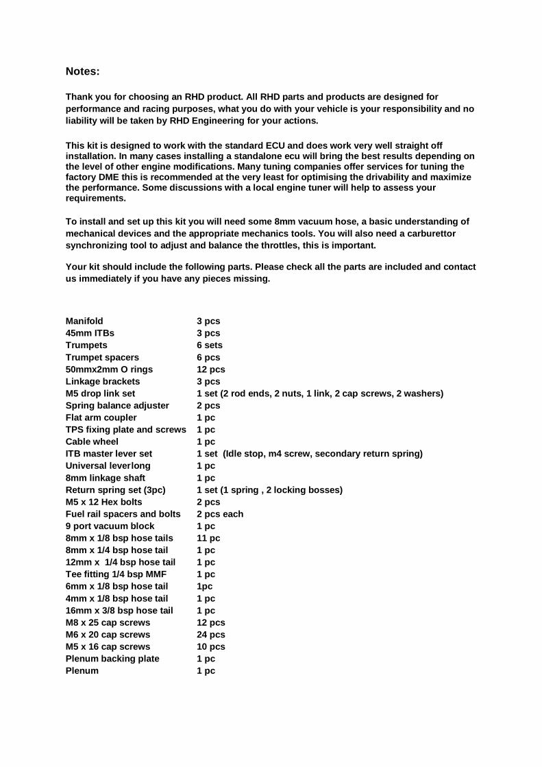
Your kit should include the following parts. Please check all the parts are included and contact us immediately if you have any pieces missing.
Manifold 3 pcs 45mm ITBs 3 pcs Trumpets 6 sets Trumpet spacers 6 pcs 50mmx2mm O rings 12 pcs Linkage brackets 3 pcs M5 drop link set 1 set (2 rod ends, 2 nuts, 1 link , 2 cap screws, 2 washers) Spring balance adjuster 2 pcs Flat arm coupler 1 pc TPS fixing plate and screws 1 pc Cable wheel 1 pc ITB master lever set 1 set (Idle stop, m4 screw, secondary return spring) Universal lever long 1 pc 8mm linkage shaft 1 pc Return spring set (3pc) 1 set (1 spring , 2 locking bosses) M5 x 12 Hex bolts 2 pcs Fuel rail spacers and bolts 2 pcs each 9 port vacuum block 1 pc 8mm x 1/8 bsp hose tails 11 pc 8mm x 1/4 bsp hose tail 1 pc 12mm x 1/4 bsp hose tail 1 pc Tee fitting 1/4 bsp MMF 1 pc 6mm x 1/8 bsp hose tail 1pc 4mm x 1/8 bsp hose tail 1 pc 16mm x 3/8 bsp hose tail 1 pc M8 x 25 cap screws 12 pcs M6 x 20 cap screws 24 pcs M5 x 16 cap screws 10 pcs Plenum backing plate 1 pc Plenum 1 pc

Assembly Procedure: Assemble the throttles leaving the balance adjuster s only slightly tight. Adjust the balance adjuster screw so it protrudes at lease 2mm towards the J spring. Install the manifolds and attach the throttles remember to install the linkag e mounting plate on the centre throttle. Make sure all the throttles are fully closed before you fully tighten the clamps on the balance adjusters. Next install the linkage and idle circui t parts and install the trumpet spacers only, no backing plate, trumpets or plenum for the moment. Now you can start the engine and synchronization the throttles, this is EXTREAMLY sensitive and essential for smooth idle and good light thrott le driving. To do this you will need the use of a synchronizer such as the one pictured below. Op en the idle stop screw until the engine is running at least 1000rpm then fit the synchronizer t o each trumpet. Adjust the balance couplings until the flow into each runner is exactl y the same. Adjust the idle stop back down to the desired idle speed.
Plenum: Remove the spacers then build an assembly of the ba cking plate spacers and trumpets leaving all the screws loose. Bolt on the plenum and fully tighten. Install the whole assembly back onto the engine again making sure the screws betwee n the trumpets and spacers are nice and loose this will make it easier align and attach the spacers back onto the throttle bodies. Install all the screws before any of them are tightened. La stly tighten the spacers onto the trumpets and backing plate

Assembly Notes:
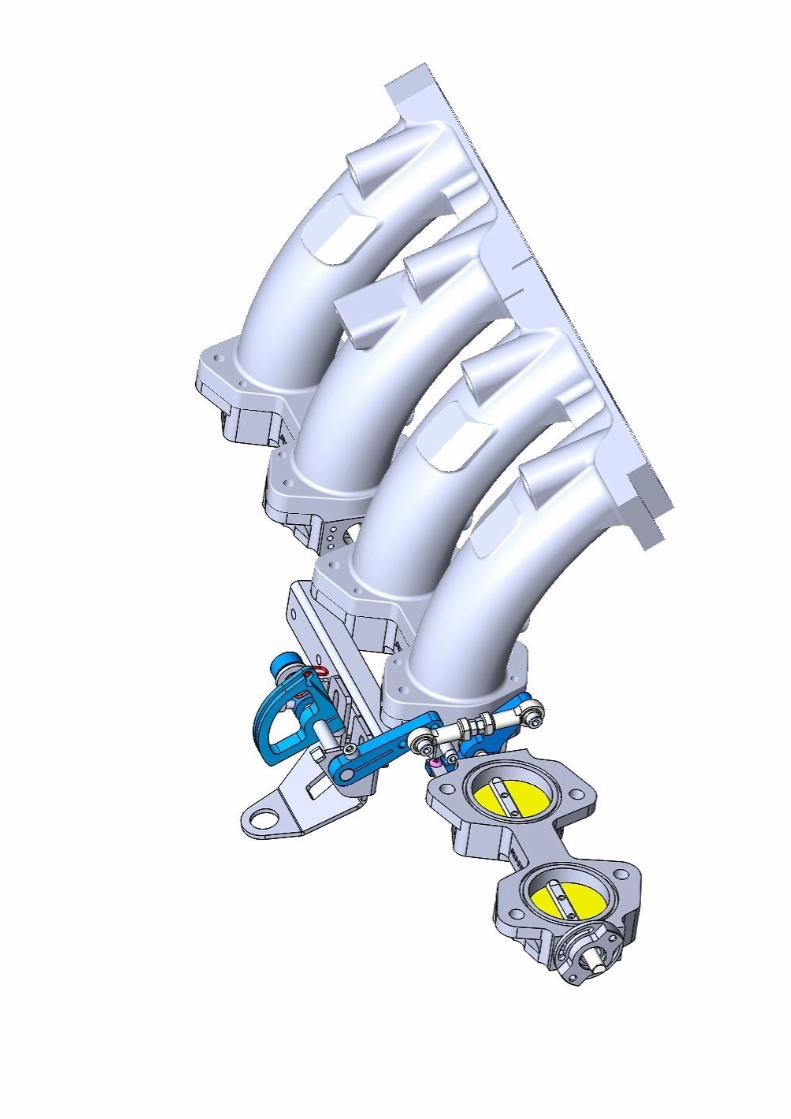
Study the following drawings very closely they show the EXACT placement of all the fittings and linkage parts Note: there are small washers required UNDER the m5 rod end drop link parts this is essential to allow the m5 rod end bearing to have enough clea rance as the linkage moves through its travel. The small return spring on the master ITB is only i ntended as a SECONDARY spring to ensure the throttles close should any linkage part becomes loose or disconnected. A second main return spring is included this can be preloaded up to a maximum of 180 degrees to add the desired amount of pedal resistance. For nice progressive throttle action keep the drop link as short as possible. However if your ITB does not reach full throttle when the pedal is fully depressed then adjusting the drop link to a longer length and resetting the cable slack wi ll alter the mechanism gain and will enable the throttle to reach full open. Make sure the linkage moves freely and smoothly wit hout any binding. It is important the ITB linkage doesn’t reach full throttle when there is s till lots of extra travel on the pedal this will over load your cable and ITB linkage resulting in p ossible damage or premature failure. Note: For correct brake booster operation you will need to attach the vacuum hose to the T fitting provided on the manifold. The booster will work exactly as it did before running from just 1 cylinder. The vacuum from 1 cylinder is much stronger than the signal from the vacuum accumulator block! DO NOT connect the booster line to the vacuum block! It is essential that the small plastic 1-way valve fitted to the factory booster line is maintained.