Embed Size (px)
Citation preview

C O U N T Y O F S A N D I E G O B M P D E S I G N M A N U A L
February 26, 2016
Appendix
E BMP Design Fact Sheets

C O U N T Y O F S A N D I E G O B M P D E S I G N M A N U A L
February 26, 2016
This page was left intentionally blank.

Appendix E: BMP Design Fact Sheets
E-1 February 26, 2016
Appendix E BMP Design Fact SheetsThe following fact sheets were developed to assist the project applicants with designing BMPs to meet the storm water obligations:
MS4 Category Manual Category Design Fact Sheet Typical Design
Source Control Source Control
SC: Source Control BMP Requirements SC-6A: Large Trash Generating Facilities SC-6B: Animal Facilities SC-6C: Plant Nurseries and Garden Centers SC-6D: Automotive-related Uses
Site Design Site Design
SD-A Tree Wells SD-B: Impervious Area Dispersion SD-C: Green Roofs SD-D: Permeable Pavement (Site Design BMP) SD-E: Rain Barrels SD-F: Amended Soil
Retention
Harvest and Use HU-1: Cistern
Infiltration
INF-1: Infiltration Basins INF-2: Bioretention INF-3: Permeable Pavement (Pollutant Control)
Partial Retention PR-1: Biofiltration with Partial Retention
Biofiltration BiofiltrationBF-1: Biofiltration BF-2: Nutrient Sensitive Media Design BF-3: Proprietary Biofiltration
Flow-thru Treatment Control
Flow-thru Treatment Control with Alternative Compliance
FT-1: Vegetated Swales FT-2: Media Filters FT-3: Sand Filters FT-4: Dry Extended Detention Basin FT-5: Proprietary Flow-thru Treatment Control
PL: Plant List for Bioretention Facilities

Appendix E: BMP Design Fact Sheets
E-2 February 26, 2016
This page was left intentionally blank.

Appendix E: BMP Design Fact Sheets
E-3 February 26, 2016
E.1 Source Control BMP Requirements Worksheet E.1-1: Source Control BMP Requirements
How to comply: Projects must comply with this requirement by implementing all source control BMPs listed in this section that are applicable and feasible for their project. Applicability must be determined through consideration of the development project’s features and anticipated pollutant sources. Appendix E.1 provides guidance for identifying source control BMPs applicable to a project. The Standard and PDP SWQMP templates include sections that must be used to document compliance with source control BMP requirements.
How to use this worksheet:
1. Review Column 1 and identify which of these potential sources of storm water pollutants apply to your site. Check each box that applies.
2. Review Column 2 and incorporate all of the corresponding applicable BMPs in your project site plan. 3. Review Columns 3 and 4 and incorporate all of the corresponding applicable permanent controls and operational BMPs in a table in your project-specific storm water management report. Describe your specific BMPs in an accompanying narrative, and explain any special conditions or situations that required omitting BMPs or substituting alternatives.
Appendix E: BMP Design Fact Sheets
E-4 February 26, 2016
If These Sources Will Be on the Project Site … … Then Your SWQMP Must Consider These Source Control BMPs
1 Potential Sources of Runoff Pollutants
2 Permanent Controls—Show on
Drawings
3 Permanent Controls—List in Table
and Narrative
4 Operational BMPs—Include in
Table and Narrative
A. Onsite storm drain inlets
Not Applicable
Locations of inlets. Mark all inlets with the words “No Dumping! Flows to Bay” or similar. See stencil template provided in Appendix I-4
Maintain and periodically repaint or replace inlet markings.
Provide storm water pollution prevention information to new site owners, lessees, or operators.
See applicable operational BMPs in Fact Sheet SC-44, “Drainage System Maintenance,” in the CASQA Storm Water Quality Handbooks at www.casqa.org/resources/bmp-handbooks/municipal-bmp-handbook.
Include the following in lease agreements: “Tenant shall not allow anyone to discharge anything to storm drains or to store or deposit materials so as to create a potential discharge to storm drains.”

Appendix E: BMP Design Fact Sheets
E-5 February 26, 2016
If These Sources Will Be on the Project Site … … Then Your SWQMP must consider These Source Control BMPs
1 Potential Sources of Runoff Pollutants
2 Permanent Controls—Show on
Drawings
3 Permanent Controls—List in Table
and Narrative
4 Operational BMPs—Include in
Table and Narrative
B. Interior floor drains and elevator shaft sump pumps
Not Applicable
State that interior floor drains and elevator shaft sump pumps will be plumbed to sanitary sewer.
Inspect and maintain drains to prevent blockages and overflow.
C. Interior parking garages
Not Applicable
State that parking garage floor drains will be plumbed to the sanitary sewer.
Inspect and maintain drains to prevent blockages and overflow.
D1. Need for future indoor & structural pest control
Not Applicable
Note building design features that discourage entry of pests.
Provide Integrated Pest Management information to owners, lessees, and operators.

Appendix E: BMP Design Fact Sheets
E-6 February 26, 2016
If These Sources Will Be on the Project Site … … Then Your SWQMP must consider These Source Control BMPs
1 Potential Sources of Runoff Pollutants
2 Permanent Controls—Show on
Drawings
3 Permanent Controls—List in Table and
Narrative
4 Operational BMPs—Include in
Table and Narrative
D2. Landscape/ Outdoor Pesticide Use
Not Applicable
Show locations of existing trees or areas of shrubs and ground cover to be undisturbed and retained.
Show self-retaining landscape areas, if any.
Show storm water treatment facilities.
State that final landscape plans will accomplish all of the following. Preserve existing drought tolerant
trees, shrubs, and ground cover to the maximum extent possible.
Design landscaping to minimize irrigation and runoff, to promote surface infiltration where appropriate, and to minimize the use of fertilizers and pesticides that can contribute to storm water pollution.
Where landscaped areas are used to retain or detain storm water, specify plants that are tolerant of periodic saturated soil conditions.
Consider using pest-resistant plants, especially adjacent to hardscape.
To ensure successful establishment, select plants appropriate to site soils, slopes, climate, sun, wind, rain, land use, air movement, ecological consistency, and plant interactions.
Maintain landscaping using minimum or no pesticides.
See applicable operational BMPs in Fact Sheet SC-41, “Building and Grounds Maintenance,” in the CASQA Storm Water Quality Handbooks at www.casqa.org/resources/bmp-handbooks/municipal-bmp-handbook.
Provide IPM information to new owners, lessees and operators.

Appendix E: BMP Design Fact Sheets
E-7 February 26, 2016
If These Sources Will Be on the Project Site … … Then Your SWQMP must consider These Source Control BMPs
1 Potential Sources of Runoff Pollutants
2 Permanent Controls—Show on
Drawings
3 Permanent Controls—List in Table
and Narrative
4 Operational BMPs—Include
in Table and Narrative
E. Pools, spas, ponds, decorative fountains, and other water features.
Not Applicable
Show location of water feature and a sanitary sewer cleanout in an accessible area within 10 feet.
If the local municipality requires pools to be plumbed to the sanitary sewer, place a note on the plans and state in the narrative that this connection will be made according to local requirements.
See applicable operational BMPs in Fact Sheet SC-72, “Fountain and Pool Maintenance,” in the CASQA Storm Water Quality Handbooks at www.casqa.org/resources/bmp-handbooks/municipal-bmp-handbook.
F. Food service Not Applicable
For restaurants, grocery stores, and other food service operations, show location (indoors or in a covered area outdoors) of a floor sink or other area for cleaning floor mats, containers, and equipment.
On the drawing, show a note that this drain will be connected to a grease interceptor before discharging to the sanitary sewer.
Describe the location and features of the designated cleaning area.
Describe the items to be cleaned in this facility and how it has been sized to ensure that the largest items can be accommodated.

Appendix E: BMP Design Fact Sheets
E-8 February 26, 2016
If These Sources Will Be on the Project Site
… … Then Your SWQMP must consider These Source Control BMPs
1 Potential Sources
of
2 Permanent Controls—Show
on Drawings
3 Permanent Controls—List
in Table and Narrative
4 Operational BMPs—Include in
Table and Narrative
G. Refuse areas Not Applicable
Show where site refuse and recycled materials will be handled and stored for pickup. See local municipal requirements for sizes and other details of refuse areas.
If dumpsters or other receptacles are outdoors, show how the designated area will be covered, graded, and paved to prevent run- on and show locations of berms to prevent runoff from the area. Also show how the designated area will be protected from wind dispersal.
Any drains from dumpsters, compactors, and tallow bin areas must be connected to a grease removal device before discharge to sanitary sewer.
State how site refuse will be handled and provide supporting detail to what is shown on plans.
State that signs will be posted on or near dumpsters with the words “Do not dump hazardous materials here” or similar.
State how the following will be implemented: Provide adequate number of receptacles. Inspect receptacles regularly; repair or replace leaky receptacles. Keep receptacles covered. Prohibit/prevent dumping of liquid or hazardous wastes. Post “no hazardous materials” signs. Inspect and pick up litter daily and clean up spills immediately. Keep spill control materials available on- site. See Fact Sheet SC-34, “Waste Handling and Disposal” in the CASQA Storm Water Quality Handbooks at www.casqa.org/resources/bmp-handbooks/municipal-bmp-handbook.

Appendix E: BMP Design Fact Sheets
E-9 February 26, 2016
If These Sources Will Be on the Project Site … … Then Your SWQMP must consider These Source Control BMPs
1 Potential Sources of Runoff Pollutants
2 Permanent Controls—Show on
Drawings
3 Permanent Controls—List in Table and
Narrative
4 Operational BMPs—Include
in Table and Narrative Table and Narrative
H. Industrial processes.
Not Applicable
Show process area. If industrial processes are to be located onsite, state: “All process activities to be performed indoors. No processes to drain to exterior or to storm drain system.”
See Fact Sheet SC-10, “Non- Storm Water Discharges” in the CASQA Storm Water Quality Handbooks at https://www.casqa.org/resources/bmp-handbooks.
I. Outdoor storage of equipment or materials. (See rows J and K for source control measures for vehicle cleaning, repair, and maintenance.)
Not Applicable
Show any outdoor storage areas, including how materials will be covered. Show how areas will be graded and bermed to prevent run-on or runoff from area and protected from wind dispersal.
Storage of non-hazardous liquids must be covered by a roof and/or drain to the sanitary sewer system, and be contained by berms, dikes, liners, or vaults.
Storage of hazardous materials and wastes must be in compliance with the local hazardous materials ordinance and a Hazardous Materials Management Plan for the site.
Include a detailed description of materials to be stored, storage areas, and structural features to prevent pollutants from entering storm drains. Where appropriate, reference documentation of compliance with the requirements of local Hazardous Materials Programs for: Hazardous Waste Generation
Hazardous Materials Release Response and Inventory
California Accidental Release Prevention Program
Aboveground Storage Tank
Uniform Fire Code Article 80 Section 103(b) & (c) 1991
Underground Storage Tank
See the Fact Sheets SC-31, “Outdoor Liquid Container Storage” and SC-33, “Outdoor Storage of Raw Materials” in the CASQA Storm Water Quality Handbooks at www.casqa.org/resources/bmp-handbooks/municipal-bmp-handbook.

Appendix E: BMP Design Fact Sheets
E-10 February 26, 2016
If These Sources Will Be on the Project Site … … Then Your SWQMP must consider These Source Control BMPs
1 Potential Sources of Runoff Pollutants
2 Permanent Controls—Show on Drawings
3 Permanent Controls—List in
Table and Narrative
4 Operational BMPs—Include in
Table and Narrative
J. Vehicle and Equipment Cleaning
Not Applicable
Show on drawings as appropriate:
(1) Commercial/industrial facilities having vehicle /equipment cleaning needs must either provide a covered, bermed area for washing activities or discourage vehicle/equipment washing by removing hose bibs and installing signs prohibiting such uses. (2) Multi-dwelling complexes must have a paved, bermed, and covered car wash area (unless car washing is prohibited onsite and hoses are provided with an automatic shut- off to discourage such use). (3) Washing areas for cars, vehicles, and equipment must be paved, designed to prevent run-on to or runoff from the area, and plumbed to drain to the sanitary sewer. (4) Commercial car wash facilities must be designed such that no runoff from the facility is discharged to the storm drain system. Wastewater from the facility must discharge to the sanitary sewer, or a wastewater reclamation system must be installed.
If a car wash area is not provided, describe measures taken to discourage onsite car washing and explain how these will be enforced.
Describe operational measures to implement the following (if applicable):
Washwater from vehicle and equipment washing operations must not be discharged to the storm drain system.
Car dealerships and similar may rinse cars with water only.
See Fact Sheet SC-21, “Vehicle and Equipment Cleaning,” in the CASQA Storm Water Quality Handbooks at www.casqa.org/resources/bmp-handbooks/municipal-bmp-handbook.

Appendix E: BMP Design Fact Sheets
E-11 February 26, 2016
If These Sources Will Be on the Project Site … … Then Your SWQMP must consider These Source Control BMPs
1 Potential Sources of Runoff Pollutants
2 Permanent Controls—Show on
Drawings
3 Permanent Controls—List in
Table and Narrative
4 Operational BMPs—Include in
Table and Narrative
K. Vehicle/Equipment Repair and Maintenance
Not Applicable
Accommodate all vehicle equipment repair and maintenance indoors. Or designate an outdoor work area and design the area to protect from rainfall, run-on runoff, and wind dispersal.
Show secondary containment for exterior work areas where motor oil, brake fluid, gasoline, diesel fuel, radiator fluid, acid-containing batteries or other hazardous materials or hazardous wastes are used or stored. Drains must not be installed within the secondary containment areas.
Add a note on the plans that states either (1) there are no floor drains, or (2) floor drains are connected to wastewater pretreatment systems prior to discharge to the sanitary sewer and an industrial waste discharge permit will be obtained.
State that no vehicle repair or maintenance will be done outdoors, or else describe the required features of the outdoor work area.
State that there are no floor drains or if there are floor drains, note the agency from which an industrial waste discharge permit will be obtained and that the design meets that agency’s requirements.
State that there are no tanks, containers or sinks to be used for parts cleaning or rinsing or, if there are, note the agency from which an industrial waste discharge permit will be obtained and that the design meets that agency’s requirements.
In the report, note that all of the following restrictions apply to use the site: No person must dispose of, nor permit
the disposal, directly or indirectly of vehicle fluids, hazardous materials, or rinsewater from parts cleaning into storm drains.
No vehicle fluid removal must be performed outside a building, nor on asphalt or ground surfaces, whether inside or outside a building, except in such a manner as to ensure that any spilled fluid will be in an area of secondary containment. Leaking vehicle fluids must be contained or drained from the vehicle immediately.
No person must leave unattended drip parts or other open containers containing vehicle fluid, unless such containers are in use or in an area of secondary containment.

Appendix E: BMP Design Fact Sheets
E-12 February 26, 2016
If These Sources Will Be on the Project Site … … Then Your SWQMP must consider These Source Control BMPs
1 Potential Sources of Runoff Pollutants
2 Permanent Controls—Show on
Drawings
3 Permanent Controls—List
in Table and Narrative
4 Operational BMPs—Include in
Table and Narrative
L. Fuel Dispensing Areas
Not Applicable
Fueling areas16 must have impermeable floors (i.e., portland cement concrete or equivalent smooth impervious surface) that are (1) graded at the minimum slope necessary to prevent ponding; and (2) separated from the rest of the site by a grade break that prevents run-on of storm water to the MEP.
Fueling areas must be covered by a canopy that extends a minimum of ten feet in each direction from each pump. [Alternative: The fueling area must be covered and the cover’s minimum dimensions must be equal to or greater than the area within the grade break or fuel dispensing area1.] The canopy [or cover] must not drain onto the fueling area.
The property owner must dry sweep the fueling area routinely.
See the Business Guide Sheet, “Automotive Service—Service Stations” in the CASQA Storm Water Quality Handbooks at https://www.casqa.org/resources/bmp-handbooks.
16 The fueling area must be defined as the area extending a minimum of 6.5 feet from the corner of each fuel dispenser or the length at which the hose and nozzle assembly may be operated plus a minimum of one foot, whichever is greater.
Appendix E: BMP Design Fact Sheets
E-13 February 26, 2016
If These Sources Will Be on the Project Site … … Then Your SWQMP must consider These Source Control BMPs
1 Potential Sources of Runoff Pollutants
2 Permanent Controls—Show on
Drawings
3 Permanent
Controls—List in
4 Operational BMPs—Include in
Table and Narrative
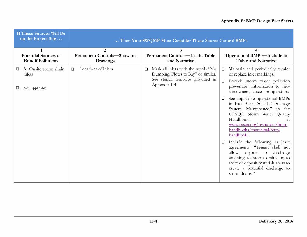
M. Loading Docks Not Applicable
Show a preliminary design for the loading dock area, including roofing and drainage. Loading docks must be covered and/or graded to minimize run-on to and runoff from the loading area. Roof downspouts must be positioned to direct storm water away from the loading area. Water from loading dock areas should be drained to the sanitary sewer where feasible. Direct connections to storm drains from depressed loading docks are prohibited.
Loading dock areas draining directly to the sanitary sewer must be equipped with a spill control valve or equivalent device, which must be kept closed during periods of operation.
Provide a roof overhang over the loading area or install door skirts (cowling) at each bay that enclose the end of the trailer.
Move loaded and unloaded items indoors as soon as possible.
See Fact Sheet SC-30, “Outdoor Loading and Unloading,” in the CASQA Storm Water Quality Handbooks at www.casqa.org/resources/bmp-handbooks/municipal-bmp-handbook.

Appendix E: BMP Design Fact Sheets
E-14 February 26, 2016
If These Sources Will Be on the Project Site … … Then Your SWQMP must consider These Source Control BMPs
1 Potential Sources of Runoff Pollutants
2 Permanent Controls—
Show on Drawings
3 Permanent Controls—List in Table and
Narrative
4 Operational BMPs—Include in
Table and Narrative
N. Fire Sprinkler Test Water
Not Applicable
Provide a means to drain fire sprinkler test water to the sanitary sewer.
See the note in Fact Sheet SC-41, “Building and Grounds Maintenance,” in the CASQA Storm Water Quality Handbooks at www.casqa.org/resources/bmp-handbooks/municipal-bmp-handbook
O. Miscellaneous Drain or Wash Water Boiler drain lines
Condensate drain lines
Rooftop equipment
Drainage sumps
Roofing, gutters, and trim
Not Applicable
Boiler drain lines must be directly or indirectly connected to the sanitary sewer system and may not discharge to the storm drain system.
Condensate drain lines may discharge to landscaped areas if the flow is small enough that runoff will not occur. Condensate drain lines may not discharge to the storm drain system.
Rooftop mounted equipment with potential to produce pollutants must be roofed and/or have secondary containment.
Any drainage sumps onsite must feature a sediment sump to reduce the quantity of sediment in pumped water.
Avoid roofing, gutters, and trim made of copper or other unprotected metals that may leach into runoff.

Appendix E: BMP Design Fact Sheets
E-15 February 26, 2016
If These Sources Will Be on the Project Site … … Then Your SWQMP must consider These Source Control BMPs
1 Potential Sources of Runoff Pollutants
2 Permanent Controls—Show on
Drawings
3 Permanent Controls—List in
Table and Narrative
4 Operational BMPs—Include in
Table and Narrative
P. Plazas, sidewalks, and parking lots.
Not Applicable
Plazas, sidewalks, and parking lots must be swept regularly to prevent the accumulation of litter and debris.
Debris from pressure washing must be collected to prevent entry into the storm drain system. Washwater containing any cleaning agent or degreaser must be collected and discharged to the sanitary sewer and not discharged to a storm drain.

Appendix E: BMP Design Fact Sheets
E-16 February 26, 2016
This page was left intentionally blank.

Appendix E: BMP Design Fact Sheets
E-17 February 26, 2016
E.2 SC-6A Large Trash Generating Facilities17
Description
Storm water runoff from areas where trash is stored or disposed of can be polluted. In addition, loose trash and debris can be easily transported by water or wind to nearby storm drain inlets, channels, and/or creeks. Trash generating facilities that generate large amounts of trash require special attention to protect trash storage areas from rainfall, run-on, runoff, and wind dispersal. Large trash generating, or trash build-up areas, include but are not limited to restaurants, supermarkets, “big box” retail stores serving food, and pet stores. The County Engineer may designate additional facilities if they are likely to generate or accumulate large quantities of trash.
Design Adaptations for Project Goals
Source control BMPs reduce the amount of pollutants that are generated. This fact sheet contains details on the additional measures required to prevent or reduce pollutants in storm water runoff associated with trash storage and handling for large trash generating facilities. The requirements presented here are in addition to the requirements of SC-5 which requires all development projects to protect trash storage areas from rainfall, run-on, runoff, and
17 Source: City of San Diego Storm Water Standards
MS4 Permit Category Source Control
Manual Category Source Control Applicable Performance Standard Source Control Primary Benefits Source Control

Appendix E: BMP Design Fact Sheets
E-18 February 26, 2016
wind dispersal:
• Areas where trash containers are stored must be enclosed on four sides to prevent off-site transport of trash. Four-sided trash enclosures typically consist of three walled sides and one gated side. Trash enclosures limit the potential for trash to pollute storm water runoff by limiting mobilization mechanisms (runoff, run-on, and wind dispersal).
• Trash enclosures must be covered to minimize direct precipitation and prevent rainfall from entering enclosures. Structural overhead covers are required as container lids are often left open.
• Enclosures must be hydraulically isolated from surrounding areas. Slabs shall be sloped such that any leaked materials will be contained within the enclosure. Drains must be provided that capture and direct potential leaks to the sanitary sewer or appropriate BMPs.
• Divert runoff from surrounding areas away from the enclosure to prevent contamination and dispersion of collected materials.
• Owner must provide BMP storm water training to employees. Employee participation is required to ensure that enclosures are properly maintained and kept clean.
Design Criteria and Considerations
All trash shall be stored in weather-protected receptacles/bins and recyclable materials shall be protected against adverse weather conditions, which might render the collected materials unmarketable. Trash enclosure dimensions will vary based on projected usage and the following information is offered as an aid in planning new projects. Businesses that use dumpsters must design the enclosure to accommodate three-yard containers at a minimum. The tenants may use any dumpster size that is appropriate for their needs, but the enclosure must be able to accommodate different tenants with varying waste production, including any recycling requirements. The design of the enclosure must be signed and sealed by a California licensed engineer. Substantiating structural calculations may be required. The location and design of the enclosure will require review and approval by the County Engineer. Building permits may be required. The following recommendations for typical bin sizes are adopted from the City of Escondido trash enclosure guidelines. The following bin/container measurements are approximate (add 8” to width for side pockets):
Typical Trash Bin Sizes
Size Width Depth Height (front) Height (back)
3 cubic yard 72” bin, 81” plus lid 43” 42” 70” 4 cubic yard 72” bin, 81” plus lid 56” 72” 72”

Appendix E: BMP Design Fact Sheets
E-19 February 26, 2016
1. Enclosures shall be structurally strong and constructed of reinforced masonry block or wood panels/boards. Refer to County staff for specific guidelines.
2. The enclosure should be constructed to the following minimum inside dimensions to
accommodate three cubic-yard dumpsters (larger enclosures may be necessary to accommodate additional trash bins, recycling bins, and accessibility)
No. of Bins Loading Width Depth Height One Front 6' 6' 6' One Side 8' 8' 6' Two Front 16' 6' 6' Two Side 8' 16' 6'
3. The enclosure slab should be designed to keep storm water drainage out of the enclosure area, typically sloped at 0.5%. Slab construction specifications will vary according to methods of construction, but should be at least 4 inches of reinforced concrete.
4. Sturdy gates/doors shall be installed on all enclosures. Gates should not be mounted directly onto the block wall or inside of enclosure. The enclosure should include hardware to secure the gate’s doors both open and closed (i.e., cane bolt w/sleeve and latch between doors and sleeve in pavement).
5. To prevent trash enclosures from contributing to storm water runoff pollution, all enclosures must be fitted with a roof deigned to drain into on-site landscape areas (where necessary) and/or to appropriate BMPs. The roof must provide sufficient clearance to allow the dumpster lid to open to the 90 degree position.
6. Enclosure roofs not conforming to County specifications for Patio Covers may require
a building permi t . Generally roofs not more than 12 feet in height above grade and constructed with conventional light-frame wood construction are considered acceptable. The use of metal roofs is not recommended as they can act as a source of pollutants.
7. Dumpsters associated with food establishments shall be sized per County Health Department requirements for wash down. Drains shall be connected to the business grease interceptor.

Appendix E: BMP Design Fact Sheets
E-20 February 26, 2016
This page was left intentionally blank.

Appendix E: BMP Design Fact Sheets
E-21 February 26, 2016
E.3 SC-6B Animal Facilities18
Description
Animal facilities have an elevated potential for bacterial loading. If animal fecal material comes into contact with storm water, the storm water can become polluted. Animal facilities include but are not limited to animal shelters, dog daycare centers, veterinary clinics, groomers, pet care stores, and breeding, boarding, and training facilities. The County Engineer may designate additional facilities where animal fecal material is likely to be found.
Design Adaptations for Project Goals
Source control BMPs reduce the amount of pollutants that are generated. This fact sheet contains details on the additional measures required to prevent or reduce pollutants in storm water runoff associated with animal facilities. The requirements presented here are in addition to the source control requirements for all projects:
• Dry weather runoff must be controlled. Dry weather runoff from hosed off areas as part of animal facility operations must not drain to the MS4. Dry weather flows should be retained on-site through implementation of BMPs or collected and discharged to the sanitary sewer.
• Outdoor activity areas must be identified on site plans. Plan reviewers must be able to ensure that runoff from these areas is either diverted to the sanitary sewer or directed to appropriate treatment BMPs. On-site inspection of facilities, grading, and drainage may be required.
18 Source: City of San Diego Storm Water Standards
MS4 Permit Category Source Control
Manual Category Source Control Applicable Performance Standard Source Control Primary Benefits Source Control

Appendix E: BMP Design Fact Sheets
E-22 February 26, 2016
• Trash enclosures within animal facilities must be covered to minimize direct precipitation and prevent rainfall from entering enclosures. Structural overhead covers are required as container lids are often left open.

Appendix E: BMP Design Fact Sheets
E-23 February 26, 2016
E.4 SC-6C Plant Nurseries and Garden Centers19
Description
Storm water runoff from plant nurseries and garden centers has an elevated risk of being polluted by organics, nutrients, and/or pesticides. Nurseries and garden centers require special attention to protect against these elevated risks. Plant nurseries and garden centers include but are not limited to commercial facilities that grow, distribute, sell, or store plants and plant material. The County Engineer may designate additional facilities if they are likely to be a source of organics, nutrients or pesticides.
Design Adaptations for Project Goals
Source control BMPs reduce the amount of pollutants that are generated. This fact sheet contains details on the additional measures required to prevent or reduce pollutants in storm water runoff associated with plant nurseries or garden center facilities. The requirements presented here are in addition to the requirements of SC-1 through SC-5 which require all development projects to avoid and reduce pollutants in storm water runoff:
• Owner must provide BMP stormwater training to appropriate employees. Employee participation is required to ensure that source controls are properly maintained and behavioral BMPs are followed.
• Eliminate overwatering and overspraying of plants. Overwatering and overspraying of plants increases dry weather flows and pollutant loading, and wastes water. Delivery
19 Source: City of San Diego Storm Water Standards
MS4 Permit Category Source Control
Manual Category Source Control Applicable Performance Standard Source Control Primary Benefits Source Control

Appendix E: BMP Design Fact Sheets
E-24 February 26, 2016
systems and schedules should account for different plant types and containers.
• Discharges from outdoor watering areas must be controlled. Regular runoff from outdoor watering can contribute un-authorized dry weather flows to the MS4 (e.g., runoff from watering the plants at garden centers). Runoff water is also likely to be polluted by potting soil mixes and plants that contain fertilizers and/or pesticides. So, regular runoff should be treated and/or retained on-site through BMPs or discharged to the sanitary sewer.

Appendix E: BMP Design Fact Sheets
E-25 February 26, 2016
E.5 SC-6D Automotive Facilities20
Description
Storm water runoff from automotive facilities can pollute storm water runoff with oils and grease, metals, and other pollutants. Pollutants sources can include maintenance and repair activities, outside storage areas, liquid material storage, and others. Automotive facilities require additional measures because of the potential impact of pollutants. Automotive facilities include but are not limited to facilities that perform maintenance or repair of vehicles, vehicle washing facilities, and retail gasoline outlets. County staff may designate additional facilities if they are likely sources of storm water pollutants.
Design Adaptations for Project Goals Source control BMPs reduce the amount of pollutants that are generated. This fact sheet contains details on the additional measures required to prevent or reduce pollutants in storm water runoff associated with automotive facilities. The requirements presented here are in addition to the requirements of Sections 4.2.1 through 4.2.6, which require all development projects avoid and reduce pollutants in storm water runoff:
• Auto repair, maintenance activities, fueling, and vehicle washing must be conducted in covered areas. Activity areas must be protected from precipitation by permanent canopy or roof structures. Covers 10 feet high or less should have a minimum overhang of 3 feet on each side, covers higher than 10 feet should have a minimum overhang of 5 feet on each side. Overhang should be measured from the perimeter of the hydraulically isolated activity area.
20 Source: City of San Diego Storm Water Standards
MS4 Permit Category Source Control
Manual Category Source Control Applicable Performance Standard Source Control Primary Benefits Source Control

Appendix E: BMP Design Fact Sheets
E-26 February 26, 2016
• Hydraulically isolate activity areas. Activity areas should be protected from run-on that can mobilize pollutants and pollute uncontaminated storm water through the use of grading, berms, or drains. Direct drainage from the hydraulically isolated area to an approved sanitary sewer or a BMP.
• Pave activity areas with hydraulic concrete or appropriately sealed asphalt cement.
Unpaved activity areas could contaminate ground water. So all activity area, including area for fueling vehicles or equipment shall be paved with hydraulic concrete. If the area is already paved with asphalt, apply an asphalt sealant to the pavement surface. Maintain the paved surface to prevent gaps and cracks.
• Provide sedimentation manhole with outlet. Automotive facilities discharging to the sanitary sewer must follow County standards for wastewater discharge.
• Provide appropriate oil controls. All equipment and vehicle washing activity areas should include oil controls. On-site wash recycling systems may be used for oil control if they meet applicable effluent discharge limits for the sanitary sewer.
• Identify auto-related usage areas on site plans and describe activities and drainage.
Plan checkers must be satisfied that grading and drainage will prevent contact between pollutants and storm water. Drains within the facilities must be connected to the sanitary sewer or a BMP. Verification may be required.
• Owner must provide BMP storm water training to employees. Employee participation is required to ensure that activity areas are properly maintained and kept clean.
Appendix E: BMP Design Fact Sheets
E-27 February 26, 2016
E.6 SD-A Tree Wells
Tree Wells (Source: County of San Diego LID Manual – EOA, Inc.)
Description
Trees planted to intercept rainfall and runoff can be used as storm water management measures that provide additional benefits beyond those typically associated with trees, including energy conservation, air quality improvement, and aesthetic enhancement. Typical storm water management benefits associated with trees include:
• Interception of rainfall – tree surfaces (roots, foliage, bark, and branches) intercept, evaporate, store, or convey precipitation to the soil before it reaches surrounding impervious surfaces
• Reduced erosion – trees protect denuded area by intercepting or reducing the velocity of rain drops as they fall through the tree canopy
• Increased infiltration – soil conditions created by roots and fallen leaves promote infiltration
• Treatment of storm water – trees provide treatment through uptake of nutrients and other storm water pollutants (phytoremediation) and support of other biological processes that break down pollutants
Typical tree well system components include:
• Trees of the appropriate species for site conditions and constraints • Available soil media reservoir volume based on mature tree size, soil type, water availability,
surrounding land uses, and project goals
MS4 Permit Category Site Design
Manual Category Site Design Applicable Performance Standard Site Design Primary Benefits Volume Reduction

Appendix E: BMP Design Fact Sheets
E-28 February 26, 2016
• Optional suspended pavement design to provide structural support for adjacent pavement without requiring compaction of underlying layers
• Optional root barrier devices as needed; a root barrier is a device installed in the ground, between a tree and the sidewalk, intended to guide roots down and away from the sidewalk in order to prevent sidewalk lifting from tree roots.
• Optional tree grates; to be considered to maximize available space for pedestrian circulation and to protect tree roots from compaction related to pedestrian circulation; tree grates are typically made up of porous material that will allow the runoff to soak through.
• Optional shallow surface depression for ponding of excess runoff • Optional planter box drain
Design Adaptations for Project Goals
Site design BMP to provide incidental treatment. Tree wells primarily function as site design BMPs for incidental treatment. Benefits from tree wells are accounted for by adjustment factors presented in Appendix B.2. This credit can apply to non-tree wells also (that meet the same criteria).
Design Criteria and Considerations
Tree wells must meet the following design criteria and considerations. Deviations from the below criteria may be approved at the discretion of the County staff if it is determined to be appropriate:
Siting and Design Intent/Rationale
□
Tree species is appropriately chosen for the development (private or public). For public rights-of-ways, local planning guidelines and zoning provisions for the permissible species and placement of trees are consulted. A list of trees appropriate for site design that can be used by all county municipalities are provided in Appendix E.25
Proper tree placement and species selection minimizes problems such as pavement damage by surface roots and poor growth.
□ Tree well placement: ensure area is graded; and the well is located so that full amount of DCV reduction drains to the well.
Minimizes short-circuiting of run off and assures DCV reductions are retained onsite.
Appendix E: BMP Design Fact Sheets
E-29 February 26, 2016
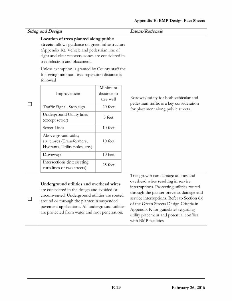
Siting and Design Intent/Rationale
□
Location of trees planted along public streets follows guidance on green infrastructure (Appendix K). Vehicle and pedestrian line of sight and clear recovery zones are considered in tree selection and placement.
Unless exemption is granted by County staff the following minimum tree separation distance is followed
Improvement Minimum distance to tree well
Traffic Signal, Stop sign 20 feet
Underground Utility lines (except sewer) 5 feet
Sewer Lines 10 feet
Above ground utility structures (Transformers, Hydrants, Utility poles, etc.)
10 feet
Driveways 10 feet
Intersections (intersecting curb lines of two streets) 25 feet
Roadway safety for both vehicular and pedestrian traffic is a key consideration for placement along public streets.
□
Underground utilities and overhead wires are considered in the design and avoided or circumvented. Underground utilities are routed around or through the planter in suspended pavement applications. All underground utilities are protected from water and root penetration.
Tree growth can damage utilities and overhead wires resulting in service interruptions. Protecting utilities routed through the planter prevents damage and service interruptions. Refer to Section 6.6 of the Green Streets Design Criteria in Appendix K for guidelines regarding utility placement and potential conflict with BMP facilities.
Appendix E: BMP Design Fact Sheets
E-30 February 26, 2016
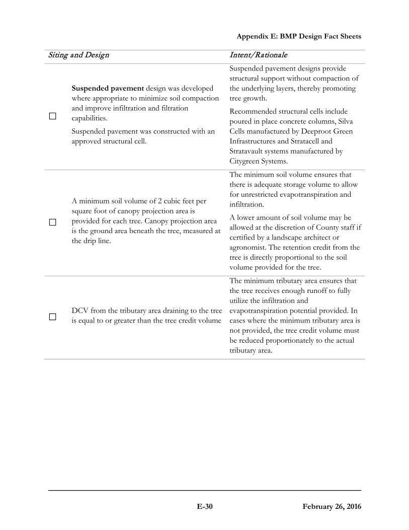
Siting and Design Intent/Rationale
□
Suspended pavement design was developed where appropriate to minimize soil compaction and improve infiltration and filtration capabilities.
Suspended pavement was constructed with an approved structural cell.
Suspended pavement designs provide structural support without compaction of the underlying layers, thereby promoting tree growth.
Recommended structural cells include poured in place concrete columns, Silva Cells manufactured by Deeproot Green Infrastructures and Stratacell and Stratavault systems manufactured by Citygreen Systems.
□ A minimum soil volume of 2 cubic feet per square foot of canopy projection area is provided for each tree. Canopy projection area is the ground area beneath the tree, measured at the drip line.
The minimum soil volume ensures that there is adequate storage volume to allow for unrestricted evapotranspiration and infiltration.
A lower amount of soil volume may be allowed at the discretion of County staff if certified by a landscape architect or agronomist. The retention credit from the tree is directly proportional to the soil volume provided for the tree.
□ DCV from the tributary area draining to the tree is equal to or greater than the tree credit volume
The minimum tributary area ensures that the tree receives enough runoff to fully utilize the infiltration and evapotranspiration potential provided. In cases where the minimum tributary area is not provided, the tree credit volume must be reduced proportionately to the actual tributary area.

Appendix E: BMP Design Fact Sheets
E-31 February 26, 2016
Siting and Design Intent/Rationale
□
Inlet opening to the tree that is at least 18 inches wide.
A minimum 2 inch drop in grade from the inlet to the finish grade of the tree.
Grated inlets are allowed for pedestrian circulation. Grates need to be ADA compliant and have sufficient slip resistance.
Design requirement to ensure that the runoff from the tributary area does not bypass the BMP.
Different inlet openings and drops in grade may be allowed at the discretion of County staff if calculations are shown that the diversion flow rate (Appendix B.1.2) from the tributary area can be conveyed to the tree. In cases where the inlet capacity is limiting the amount of runoff draining to the tree, the tree credit volume must be reduced proportionately.
Conceptual Design and Sizing Approach for Site Design
1. Determine the areas where tree wells can be used in the site design to achieve incidental treatment. Tree wells reduce runoff volumes from the site. Refer to Appendix B.2. Document the proposed tree locations in the SWQMP.
2. When trees are proposed as a storm water pollutant control BMP, applicant must complete feasibility analysis in Appendix C and D and submit detailed calculations for the DCV treated by trees. Document the proposed tree locations, feasibility analysis and sizing calculations in the SWQMP. The following calculations should be performed and the smallest of the three should be used as the volume treated by trees:
a. Delineate the DMA (tributary area) to the tree and calculate the associated DCV.
b. Calculate the required diversion flow rate using Appendix B.1.2 and size the inlet required to covey this flow rate to the tree. If the proposed inlet cannot convey the diversion flow rate for the entire tributary area, then the DCV that enters the tree should be proportionally reduced.
i. For example, 0.5 acre drains to the tree and the associated DCV is 820 ft3. The required diversion flow rate is 0.10 ft3/s, but only an inlet that can divert 0.05 ft3/s could be installed.
ii. Then the effective DCV draining to the tree = 820 ft3 * (0.05/0.10) = 420 ft3

Appendix E: BMP Design Fact Sheets
E-32 February 26, 2016
This page was left intentionally blank.

Appendix E: BMP Design Fact Sheets
E-33 February 26, 2016
E.7 SD-B Impervious Area Dispersion
Photo Credit: Orange County Technical Guidance Document
Description
Impervious area dispersion (dispersion) refers to the practice of effectively disconnecting impervious areas from directly draining to the storm drain system by routing runoff from impervious areas such as rooftops (through downspout disconnection), walkways, and driveways onto the surface of adjacent pervious areas. The intent is to slow runoff discharges, and reduce volumes. Dispersion with partial or full infiltration results in significant volume reduction by means of infiltration and evapotranspiration.
Typical dispersion components include:
• An impervious surface from which runoff flows will be routed with minimal piping to limit concentrated inflows
• Splash blocks, flow spreaders, or other means of dispersing concentrated flows and providing energy dissipation as needed
• Dedicated pervious area, typically vegetated, with in-situ soil infiltration capacity for partial or full infiltration
• Optional soil amendments to improve vegetation support, maintain infiltration rates and enhance treatment of routed flows
• Overflow route for excess flows to be conveyed from dispersion area to the storm drain system or discharge point
MS4 Permit Category Site Design
Manual Category Site Design Applicable Performance Criteria Site Design Primary Benefits Volume Reduction Peak Flow Attenuation

Appendix E: BMP Design Fact Sheets
E-34 February 26, 2016
Typical plan and section view of an Impervious Area Dispersion BMP

Appendix E: BMP Design Fact Sheets
E-35 February 26, 2016
Design Adaptations for Project Goals
Site design BMP to reduce impervious area and DCV. Impervious area dispersion primarily functions as a site design BMP for reducing the effective imperviousness of a site by providing partial or full infiltration of the flows that are routed to pervious dispersion areas and otherwise slowing down excess flows that eventually reach the storm drain system. This can significantly reduce the DCV for the site.
Design Criteria and Considerations
Dispersion must meet the following design criteria. Deviations from the below criteria may be approved at the discretion of County Staff if it is determined to be appropriate:
Siting and Design Intent/Rationale
□ Impervious area dispersion Placement: ensure area is graded; and located so that full DCV water drains to the area of dispersion
Minimizes short-circuiting of run off
□
Dispersion is over areas with soil types capable of supporting or being amended (e.g., with sand or compost) to support vegetation. Media amendments must be tested to verify that they are not a source of pollutants.
Soil must have long-term infiltration capacity for partial or full infiltration and be able to support vegetation to provide runoff treatment. Amendments to improve plant growth must not have negative impact on water quality.
□ Dispersion has vegetated sheet flow over a relatively large distance (minimum 10 feet) from inflow to overflow route.
Full or partial infiltration requires relatively large areas to be effective depending on the permeability of the underlying soils.
□ Pervious areas should be flat (with less than 5% slopes) and vegetated.
Flat slopes facilitate sheet flows and minimize velocities, thereby improving treatment and reducing the likelihood of erosion.
Inflow velocities
□ Inflow velocities are limited to 3 ft/s or less or use energy dissipation methods (e.g., riprap, level spreader) for concentrated inflows.
High inflow velocities can cause erosion, scour and/or channeling.
Dedication
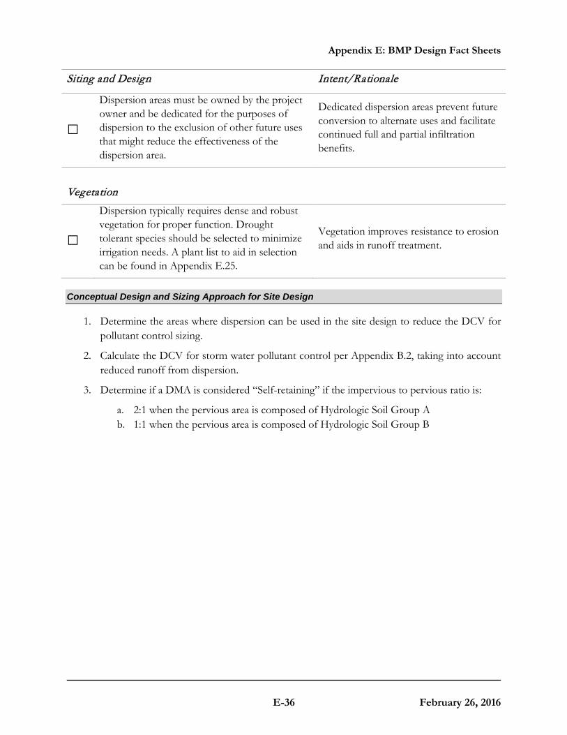
Appendix E: BMP Design Fact Sheets
E-36 February 26, 2016
Siting and Design Intent/Rationale
□ Dispersion areas must be owned by the project owner and be dedicated for the purposes of dispersion to the exclusion of other future uses that might reduce the effectiveness of the dispersion area.
Dedicated dispersion areas prevent future conversion to alternate uses and facilitate continued full and partial infiltration benefits.
Vegetation
□ Dispersion typically requires dense and robust vegetation for proper function. Drought tolerant species should be selected to minimize irrigation needs. A plant list to aid in selection can be found in Appendix E.25.
Vegetation improves resistance to erosion and aids in runoff treatment.
Conceptual Design and Sizing Approach for Site Design
1. Determine the areas where dispersion can be used in the site design to reduce the DCV for pollutant control sizing.
2. Calculate the DCV for storm water pollutant control per Appendix B.2, taking into account reduced runoff from dispersion.
3. Determine if a DMA is considered “Self-retaining” if the impervious to pervious ratio is:
a. 2:1 when the pervious area is composed of Hydrologic Soil Group A b. 1:1 when the pervious area is composed of Hydrologic Soil Group B

Appendix E: BMP Design Fact Sheets
E-37 February 26, 2016
E.8 SD-C: Green Roofs
Location: County of San Diego Operations Center, San Diego, California
Description
Green roofs are vegetated rooftop systems that reduce runoff volumes and rates, treat storm waterpollutants through filtration and plant uptake, provide additional landscape amenity, and create wildlife habitat. Additionally, green roofs reduce the heat island effect and provide acoustical control, air filtration and oxygen production. In terms of building design, they can protect against ultraviolet rays and extend the roof lifetime, as well as increase the building insulation, thereby decreasing heating and cooling costs. There are two primary types of green roofs:
• Extensive – lightweight, low maintenance system with low-profile, drought tolerant type groundcover in shallow growing medium (6 inches or less)
• Intensive – heavyweight, high maintenance system with a more garden-like configuration and diverse plantings that may include shrubs or trees in a thicker growing medium (greater than 6 inches)
Typical green roof components include, from top to bottom:
• Vegetation that is appropriate to the type of green roof system, climate, and watering conditions
• Media layer (planting mix or engineered media) capable of supporting vegetation growth
MS4 Permit CategorySite Design
Manual Category Site Design Applicable Performance Standard Site Design Primary Benefits Volume Reduction Peak Flow Attenuation

Appendix E: BMP Design Fact Sheets
E-38 February 26, 2016
• Filter fabric to prevent migration of fines (soils) into the drainage layer • Optional drainage layer to convey excess runoff • Optional root barrier • Optional insulation layer • Waterproof membrane • Structural roof support capable of withstanding the additional weight of a green roof
Typical profile of a Green Roof BMP
Design Adaptations for Project Goals
Site design BMP to provide incidental treatment. Green roofs can be used as a site design feature to reduce the impervious area of the site through replacing conventional roofing. This can reduce the DCV and flow control requirements for the site.
Design Criteria and Considerations
Green roofs must meet the following design criteria. Deviations from the below criteria may be approved at the discretion of County staff if it is determined to be appropriate:

Appendix E: BMP Design Fact Sheets
E-39 February 26, 2016
Siting and Design Intent/Rationale
□ Roof slope is ≤ 40% (Roofs that are ≤ 20% are preferred).
Steep roof slopes increases project complexity and requires supplemental anchoring.
□ Structural roof capacity design supports the calculated additional load (lbs/sq. ft) of the vegetation growing medium and additional drainage and barrier layers.
Inadequate structural capacity increases the risk for roof failure and harm to the building and occupants.
□ Design and construction is planned to be completed by an experienced green roof specialist.
A green roof specialist will minimize complications in implementation and potential structural issues that are critical to green roof success.
□ Green roof location and extent must meet fire safety provisions.
Green roof design must not negatively impact fire safety.
□ Maintenance access is included in the green roof design.
Maintenance will facilitate proper functioning of drainage and irrigation components and allow for removal of undesirable vegetation and soil testing, as needed.
Vegetation
□
Vegetation is suitable for the green roof type, climate and expected watering conditions. Perennial, self-sowing plants that are drought-tolerant (e.g., sedums, succulents) and require little to no fertilizer, pesticides or herbicides are recommended. Vegetation pre-grown at grade may allow plants to establish prior to facing harsh roof conditions.
Plants suited to the design and expected growing environment are more likely to survive.
□ Vegetation is capable of covering ≥ 90% the roof surface.
Benefits of green roofs are greater with more surface vegetation.
□ Vegetation is robust and erosion-resistant in order to withstand the anticipated rooftop environment (e.g., heat, cold, high winds).
Weak plants will not survive in extreme rooftop environments.
□ Vegetation is fire resistant. Vegetation that will not burn easily decreases the chance for fire and harm to the building and occupants.
□ Vegetation considers roof sun exposure and shaded areas based on roof slope and
The amount of sunlight the vegetation receives can inhibit growth therefore the beneficial

Appendix E: BMP Design Fact Sheets
E-40 February 26, 2016
Siting and Design Intent/Rationale
location. effects of a vegetated roof.
□ An irrigation system (e.g., drip irrigation system) is included as necessary to maintain vegetation.
Proper watering will increase plant survival, especially for new plantings.
□ Media is well-drained and is the appropriate depth required for the green roof type and vegetation supported.
Unnecessary water retention increases structural loading. An adequate media depth increases plant survival.
□ A filter fabric is used to prevent migration of media fines through the system.
Migration of media can cause clogging of the drainage layer.
□ A drainage layer is provided if needed to convey runoff safely from the roof. The drainage layer can be comprised of gravel, perforated sheeting, or other drainage materials.
Inadequate drainage increases structural loading and the risk of harm to the building and occupants.
□ A root barrier comprised of dense material to inhibit root penetration is used if the waterproof membrane will not provide root penetration protection.
Root penetration can decrease the integrity of the underlying structural roof components and increase the risk of harm to the building and occupants.
□ An insulation layer is included as needed to protect against the water in the drainage layer from extracting building heat in the winter and cool air in the summer.
Regulating thermal impacts of green roofs will aid in controlling building heating and cooling costs.
□
A waterproof membrane is used to prevent the roof runoff from vertically migrating and damaging the roofing material. A root barrier may be required to prevent roots from compromising the integrity of the membrane.
Water-damaged roof materials increase the risk of harm to the building and occupants.
Conceptual Design and Sizing Approach for Site Design
1. Determine the areas where green roofs can be used in the site design to replace conventional roofing to reduce the DCV. These green roof areas can be credited toward reducing runoff generated through representation in storm water calculations as pervious, not impervious, areas but are not credited for storm water pollutant control.
2. Calculate the DCV per Appendix B.2.

Appendix E: BMP Design Fact Sheets
E-41 February 26, 2016
E.9 SD-D Permeable Pavement (Site Design BMP)Description
Permeable pavement is pavement that allows for percolation through void spaces in the pavement surface into subsurface layers. Permeable pavements reduce runoff volumes and rates and can provide pollutant control via infiltration, filtration, sorption, sedimentation, and biodegradation processes. When used as a site design BMP, the subsurface layers are designed to provide storage of storm water runoff so that outflow rates can be controlled via infiltration into subgrade soils. Varying levels of storm water treatment and
flow control can be provided depending on the size of the permeable pavement system relative to its drainage area and the underlying infiltration rates. As a site design BMP permeable pavement areas are designed to be self-retaining and are designed primarily for direct rainfall. Self-retaining permeable pavement areas have a ratio of total drainage area (including permeable pavement) to area of permeable pavement of 1.5:1 or less. Permeable pavement surfaces can be constructed from modular paver units or paver blocks, pervious concrete, porous asphalt, and turf pavers. Sites designed with permeable pavements can significantly reduce the impervious area of the project. Reduction in impervious surfaces decreases the DCV and can reduce the footprint of treatment control and flow control BMPs.
Design Adaptations for Project Goals
Site design BMP to reduce impervious area and DCV. Permeable pavement without an underdrain can be used as a site design feature to reduce the impervious area of the site by replacing traditional pavements, including roadways, parking lots, emergency access lanes, sidewalks, trails and driveways.
Conceptual Design and Sizing Approach for Site Design
1. Determine the areas where permeable pavements can be used in the site design to replace conventional pavements to reduce the DCV. These areas can be credited toward reducing runoff generated through representation in storm water calculations as pervious, not impervious, areas but are not credited for storm water pollutant control.
2. Calculate the DCV per Appendix B.2, taking into account reduced runoff from permeable pavement areas.
Photo Credit: San Diego Low Impact
Development Design Manual
Typical Permeable Pavement Components (Top to Bottom)
Permeable surface layer Bedding layer for permeable surface Aggregate storage layer with optional underdrain(s)Optional final filter course layer over uncompacted existing subgrade

Appendix E: BMP Design Fact Sheets
E-42 February 26, 2016
E.10 SD-E Rain BarrelsDescription
Rain barrels are containers that can capture rooftop runoff and store it for future use. With controlled timing and volume release, the captured rainwater can be used for irrigation or alternative grey water between storm events, thereby reducing runoff volumes and associated pollutants to downstream waterbodies. Rain barrels tend to be smaller systems, less than 100 gallons. Treatment can be achieved when rain barrels are used as part of a treatment train along with other BMPs that use captured flows in applications that do not result in discharges into the storm drain system. Rooftops are the ideal tributary areas for rain barrels.
Design Adaptations for Project Goals
Site design BMP to reduce effective impervious area and DCV. Barrels can be used as a site design feature to reduce the effective impervious area of the site by removing roof runoff from the site discharge. This can reduce the DCV and flow control requirements for the site.
Important Considerations
Maintenance: Rain barrels require regular monitoring and cleaning to ensure that they do not become clogged with leaves or other debris. Economics: Rain barrels have low installation costs. Limitations: Due to San Diego’s arid climate, some rain barrels may fill only a few times each year.
Conceptual Design and Sizing Approach for Site Design
1. Determine the areas where rain barrels can be used in the site design to capture roof runoff to reduce the DCV. Rain barrels reduce the effective impervious area of the site by removing roof runoff from the site discharge.
2. Calculate the DCV per Appendix B.2, taking into account reduced runoff from permeable pavement areas. Credit can be taken for the full rain barrel volume when each barrel volume is smaller than 100 gallons, and meet the following criteria: total rain barrel volume is less than 0.25 DCV and landscape areas are greater than 30 percent of the project footprint. Credit for harvest and use systems that do not meet the above criteria must be based on the criteria in Appendix B.3 and HU-1 fact sheet.
Photo Credit: San Diego Low Impact
Development Design Manual
Typical Rain Barrel Components Storage container, barrel or tank for holding captured flows Inlet and associated valves and piping Outlet and associated valves and piping Overflow outlet Optional pump Optional first flush diverters Optional roof, supports, foundation, level indicator, and other accessories

Appendix E: BMP Design Fact Sheets
E-43 February 26, 2016
E.11 SD-F Amended Soil21
Description
Naturally occurring (undisturbed) topsoil and vegetation provide important storm water functions including: water infiltration; nutrient, sediment, and pollutant adsorption; sediment and pollutant biofiltration; water interflow storage and transmission; and pollutant decomposition.
Natural functions are largely lost when development strips away native topsoil and vegetation and replaces it with minimal topsoil and sod. Not only are
these important storm water functions lost, but such landscapes themselves become pollution generating pervious surfaces due to increased use of pesticides, fertilizers and other landscaping and household/industrial chemicals, the concentration of pet wastes, and pollutants that accompany roadside litter.
Amended soil attains greater storm water functions in the post development landscape, provides increased treatment of pollutants and sediments that result from development and habitation, and minimizes the need for some landscaping chemicals, thus reducing pollution through prevention.
Design Adaptations for Project Goals
Amended soil primarily functions as a site design BMP for reducing the effective imperviousness of a site by providing partial or full infiltration of the flows that are routed to amended soil areas and otherwise slowing down excess flows that eventually reach the storm drain system.
Applications and Limitations
Amending soil per these guidelines is not the same as preservation of naturally occurring topsoil and vegetation. However, amending soil will improve on-site management of storm water flow and
21 Reprinted from Guidelines and Resources for Implementing Amended Soil BMP T5.13 in WDOE Storm WaterManagement Manual for Western Washington, 2010, Washington Organic Recycling Council.
Planting bed Cross-Section

Appendix E: BMP Design Fact Sheets
E-44 February 26, 2016
water quality.
Soil organic matter can be attained through numerous materials such as compost, composted woody material, and biosolids. It is important that the materials used to meet this Amended Soil Fact Sheet be appropriate and beneficial to the plant cover to be established. Likewise, it is important that imported topsoils improve soil conditions and do not have an excessive percent of clay fines.
The amended soil layer shall have a minimum depth of eight inches except where tree roots limit the depth of incorporation of amendments needed to meet the criteria. Subsoils below the topsoil layer should be scarified at least 4 inches with some incorporation of the upper material to avoid stratified layers, where feasible.
The amended soil layer for trees shall be a minimum of three feet deep and extend at least twelve inches in all directions of the root ball when planted; the amended soil layer for shrubs shall be a minimum of two feet deep and extend at least twelve inches in all directions of the root ball when planted; the length and width must ensure the appropriate volume for the species and site.
Amended Soils can be considered infeasible on slopes greater than 25 percent. Only amended planting holes for trees and shrubs need meet these requirements. Mulching requirements still apply to slopes over 25 percent.
Design Criteria and Considerations
Soil Retention
□
Retain, in an undisturbed state, the mulch and native topsoil to the maximum extent practicable. In any areas requiring grading remove and stockpile the mulch and topsoil on site in a designated, controlled area, not adjacent to public resources and critical areas, to be reapplied to other portions of the site where feasible.
Relocated soil can be utilized to create berms or high points within the landscaping. They help contain and move water increasing the holding capacity of swales. Berms also become homes for plants that like fast drainage.

Appendix E: BMP Design Fact Sheets
E-45 February 26, 2016
Soil Quality
All areas subject to clearing and grading that have not been covered by impervious surface, incorporated into a drainage facility or engineered as structural fill or slope shall, at project completion, demonstrate the following:
□ Amended soil Shall have a minimum organic matter content of 10% dry weight in planting beds, and 5% organic matter content in turf areas, and a pH from 6.0 to 8.0 or matching the pH of the undisturbed topsoil.
Organic matter, such as leaves and twigs, feed the microbes in the soil. Microbes form part of the soil structure and act like sponges, helping the soil absorb water.
□
Use compost and other materials that meet organic content requirements:
a) The organic content for “pre-approved” amendment rates can be met only using compost that meets the definition of “composted materials” in WAC 173-350-100. This code is available online at: http://apps.leg.wa.gov/wac/default.aspx?cite=173-350
b) The compost must also have an organic matter content of 40% to 65%, and a carbon to nitrogen ratio below 25:1.
c) Calculated amendment rates may be met through use of composted materials meeting a) and b) above; or other organic materials amended to meet the carbon to nitrogen ratio requirements, and meeting the contaminant standards of Grade A Compost.
The resulting soil should be conducive to the type of vegetation to be established.
Compost contains particles that improve the overall soil structure. As compost decomposes, it encourages the formation of macroaggregate that create a more stable soil structure.

Appendix E: BMP Design Fact Sheets
E-46 February 26, 2016
Soil Quality
□
A minimum three inch layer of mulch shall be applied on all exposed soil surfaces in each landscaped area except in turf areas, creeping or rooting ground covers or direct seeding applications where mulch is contraindicated.
Organic mulch materials made from recycled or post-consumer products/materials shall take precedence over inorganic materials or virgin forest products unless the recycled post-consumer organic products are not locally available. Organic mulches are not required where prohibited by County Fire Code.
Highly flammable mulch material, such as straw or small, mini size wood chips, shall not be used in a "Hazardous Fire Area," as that term is defined in the County Fire Code.
Mulch creates a blanket protecting the soil and plant roots from temperature change, keeps moisture in by slowing down evaporation and keeps weeds from sprouting by reducing sunlight penetration.
Implementation Options
The soil quality design guidelines listed above can be met by using one of the methods listed below:
1) Leave undisturbed native vegetation and soil, and protect from compaction during construction.
2) Amend existing site topsoil or subsoil either at default “pre-approved” rates, or at custom calculated rates based on tests of the soil and amendment to achieve the organic matter content required..
3) Stockpile existing topsoil during grading, and replace it prior to planting. Stockpiled topsoil must also be amended if needed to meet the organic matter or depth requirements, either at a default “pre-approved” rate or at a custom calculated rate.
4) Import topsoil mix of sufficient organic matter content and depth to meet the requirements.
More than one method may be used on different portions of the same site. Soil that already meets the depth and organic matter quality standards, and is not compacted, does not need to be amended.

Appendix E: BMP Design Fact Sheets
E-47 February 26, 2016
Planning/Permitting/Inspection/Verification Guidelines & Procedures
Sitting and Design Intent/Rationale
□ Establish Amended Soil toward the end of construction and once established, protect from compaction, such as from large machinery use, and from erosion.
Compaction, augmenting or tilling the soil destroys the overall structure of the soil. Healthy soil has lots of tiny little pockets of air, when soils are eroded, graded or disturbed, their structure becomes compacted. Compaction is caused when the tiny air and water bubbles are squeezed out of the soil and microbes are killed.
□ Plant vegetation and mulch the amended soil area after installation.
Mulch stays on top of the soil and is never worked in. Keep mulch 1 to 6 inches away from stems of plants.
□ Leave plant debris or its equivalent on the soil surface to replenish organic matter.
Bits of leaves and twigs function as food for microbes living in the soil. Once established, the plants will eventually feed themselves off their own leaf litter.
□ Use appropriate irrigation.
Knowing your climate zones and the water needs of your landscape will help establish watering zones and watering schedules for your landscape.
Rainwater is best for both plants and microbes; provide this as much as possible when it is available.
Adjust spray irrigation so that there is no overspray on to hard surfaces. When possible, convert spray systems to drip irrigation. This will reduce runoff and allow water to infiltrate the soil.
□ Reduce and adjust, where possible, the use of irrigation, fertilizers, herbicides and pesticides, rather than continuing to implement formerly established practices.
Chemical fertilizers, herbicides and pesticides; including organic ones; kill soil microbes.

Appendix E: BMP Design Fact Sheets
E-48 February 26, 2016
Runoff Model Representation
Flow reduction credits can be taken in runoff modeling when SD-F Amended Soil is used as part of a dispersion design under the conditions described in SD-B Impervious Area Dispersion.
Areas meeting the design guidelines may be entered into approved runoff models by adjusting depression storage parameters.
Data Sources
San Diego Sustainable Landscapes Guidelines San Diego County Water Authority 2015 BMP T5.13 “Post Construction Soil Quality and Depth” Storm Water Management Manual for Western Washington, August 2012

Appendix E: BMP Design Fact Sheets
E-49 February 26, 2016
E.12 HU-1 Cistern
Photo Credit: Water Environment Research Foundation: WERF.org
Description
Cisterns are containers that can capture rooftop runoff and store it for future use. With controlled timing and volume release, the captured rainwater can be used for irrigation or alternative grey water between storm events, thereby reducing runoff volumes and associated pollutants to downstream water bodies. Cisterns are larger systems (generally>100 gallons) that can be self-contained aboveground or below ground systems. Treatment can be achieved when cisterns are used as part of a treatment train along with other BMPs that use captured flows in applications that do not result in discharges into the storm drain system. Rooftops are the ideal tributary areas for cisterns.
Typical cistern components include:
• Storage container, barrel or tank for holding captured flows
• Inlet and associated valves and piping
• Outlet and associated valves and piping
• Overflow outlet
• Optional pump
MS4 Permit Category Retention
Manual Category Harvest and Use Applicable Performance Standards Pollutant Control Flow Control Primary Benefits Volume Reduction Peak Flow Attenuation

Appendix E: BMP Design Fact Sheets
E-50 February 26, 2016
• Optional first flush diverters
• Optional roof, supports, foundation, level indicator, and other accessories
Source: City of San Diego Storm Water Standards
Design Adaptations for Project Goals
Site design BMP to reduce effective impervious area and DCV. Cisterns can be used as a site design feature to reduce the effective impervious area of the site by removing roof runoff from the site discharge. This can reduce the DCV and flow control requirements for the site.
Harvest and use for storm water pollutant control. Typical uses for captured flows include irrigation, toilet flushing, cooling system makeup, and vehicle and equipment washing.
Integrated storm water flow control and pollutant control configuration. Cisterns provide flow control in the form of volume reduction and/or peak flow attenuation and storm water treatment through elimination of discharges of pollutants. Additional flow control can be achieved by sizing the cistern to include additional detention storage and/or real-time automated flow release controls.

Appendix E: BMP Design Fact Sheets
E-51 February 26, 2016
Design Criteria and Considerations
Cisterns must meet the following design criteria. Deviations from the below criteria may be approved at the discretion of County staff if it is determined to be appropriate:
Siting and Design Intent/Rationale
□ Cisterns are sized to detain the full DCV of contributing area and empty within 36 hours.
Draining the cistern makes the storage volume available to capture the next storm.
The applicant has an option to use a different drawdown time up to 120 hours if the volume of the facility is adjusted using the percent capture method in Appendix B.4.1.
□ Cisterns are fitted with a flow control device such as an orifice or a valve to limit outflow in accordance with drawdown time requirements.
Flow control provides flow attenuation benefits and limits cistern discharge to downstream facilities during storm events.
□ Cisterns are designed to drain completely, leaving no standing water, and all entry points are fitted with traps or screens, or sealed.
Complete drainage and restricted entry prevents mosquito habitat.
□ Leaf guards and/or screens are provided to prevent debris from accumulating in the cistern.
Leaves and organic debris can clog the outlet of the cistern.
□ Access is provided for maintenance and the cistern outlets are accessible and designed to allow easy cleaning.
Properly functioning outlets are needed to maintain proper flow control in accordance with drawdown time requirements.
□ Cisterns must be designed and sited such that overflow will be conveyed safely overland to the storm drain system or discharge point.
Safe overflow conveyance prevents flooding and damage of property.
Conceptual Design and Sizing Approach for Site Design and Storm Water Pollutant Control
1. Calculate the DCV for site design per Appendix B.
2. Determine the locations on the site where cisterns can be located to capture and detain the DCV from roof areas without subsequent discharge to the storm drain system. Cisterns are best located in close proximity to building and other roofed structures to minimize piping. Cisterns can also be used as part of a treatment train upstream by increasing pollutant control through delayed runoff to infiltration BMPs such as bioretention without underdrain facilities.

Appendix E: BMP Design Fact Sheets
E-52 February 26, 2016
3. Use the sizing worksheet in Appendix B.3 to determine if full or partial capture of the DCV is achievable.
4. The remaining DCV to be treated should be calculated for use in sizing downstream BMP(s).
Conceptual Design and Sizing Approach when Storm Water Flow Control is Applicable
Control of flow rates and/or duration will typically require significant cistern volumes, and therefore the following steps should be taken prior to determination of site design and storm water pollutant control. Pre-development and allowable post-project flow rates and durations should be determined as discussed in Chapter 6 of the manual.
1. Verify that cistern siting and design criteria have been met. Design for flow control can be achieved using various design configurations, shapes, and quantities of cisterns.
2. Iteratively determine the cistern storage volume required to provide detention storage to reduce flow rates and durations to allowable limits. Flow rates and durations can be controlled from detention storage by altering outlet structure orifice size(s) and/or water control valve operation.
3. Verify that the cistern is drawdown within 36 hours. The drawdown time can be estimated by dividing the storage volume by the rate of use of harvested water.
4. If the cistern cannot fully provide the flow rate and duration control required by this manual, a downstream structure with additional storage volume or infiltration capacity such as a biofiltration can be used to provide remaining flow control.

Appendix E: BMP Design Fact Sheets
E-53 February 26, 2016
E.13 INF-1 Infiltration Basin
Photo Credit: http://www.storm waterpartners.com/facilities/basin.html
Description
An infiltration basin typically consists of an earthen basin with a flat bottom constructed in naturally pervious soils. An infiltration basin retains storm water and allows it to evaporate and/or percolate into the underlying soils. The bottom of an infiltration basin is typically vegetated with native grasses or turf grass; however other types of vegetation can be used if they can survive periodic inundation and long inter-event dry periods. Treatment is achieved primarily through infiltration, filtration, sedimentation, biochemical processes and plant uptake. Infiltration basins can be constructed as linear trenches or as underground infiltration galleries.
Typical infiltration basin components include:
• Inflow distribution mechanisms (e.g., perimeter flow spreader or filter strips)
• Energy dissipation mechanism for concentrated inflows (e.g., splash blocks or riprap)
• Forebay to provide pretreatment surface ponding for captured flows
• Vegetation selected based on basin use, climate, and ponding depth
• Uncompacted native soils at the bottom of the facility
MS4 Permit Category Retention
Manual Category Infiltration Applicable Performance Standard Pollutant Control Flow Control Primary Benefits Volume Reduction Peak Flow Attenuation

Appendix E: BMP Design Fact Sheets
E-54 February 26, 2016
• Overflow structure
Typical plan and section view of an Infiltration BMP
Design Adaptations for Project Goals
Full infiltration BMP for storm water pollutant control. Infiltration basins can be used as a pollutant control BMP, designed to infiltrate runoff from direct rainfall as well as runoff from adjacent areas that are tributary to the BMP. Infiltration basins must be designed with an infiltration storage volume (a function of the surface ponding volume) equal to the full DCV and able to meet drawdown time limitations.

Appendix E: BMP Design Fact Sheets
E-55 February 26, 2016
Integrated storm water flow control and pollutant control configuration. Infiltration basins can also be designed for flow rate and duration control by providing additional infiltration storage through increasing the surface ponding volume.
Design Criteria and Considerations
Infiltration basins must meet the following design criteria. Deviations from the below criteria may be approved at the discretion of County staff if it is determined to be appropriate:
Siting and Design Intent/Rationale
□ Placement observes geotechnical recommendations regarding potential hazards (e.g., slope stability, landslides, liquefaction zones) and setbacks (e.g., slopes, foundations, utilities).
Must not negatively impact existing site geotechnical concerns.
□ Selection and design of basin is based on infiltration feasibility criteria and appropriate design infiltration rate (See Appendix C and D).
Must operate as a full infiltration design and must be supported by drainage area and in-situ infiltration rate feasibility findings.
□ Finish grade of the facility is ≤ 2% (0% recommended).
Flatter surfaces reduce erosion and channelization with the facility.
□ Settling forebay has a volume ≥ 25% of facility volume below the forebay overflow.
A forebay to trap sediment can decrease frequency of required maintenance.
□ Infiltration of surface ponding is limited to a 36-hour drawdown time.
Prolonged surface ponding reduces volume available to capture subsequent storms.
The applicant has an option to use a surface drawdown time of up to 96 hours if the volume of the facility is adjusted using the percent capture method in Appendix B.4.1.
□ Minimum freeboard provided is ≥1 foot.
Freeboard minimizes risk of uncontrolled surface discharge.
□ Side slopes are = 3H:1V or shallower. Gentler side slopes are safer, less prone to erosion, able to establish vegetation more quickly and easier to maintain.

Appendix E: BMP Design Fact Sheets
E-56 February 26, 2016
Inflow and Overflow Structures
□ Inflow and outflow structures are accessible by required equipment (e.g., vactor truck) for inspection and maintenance.
Maintenance will prevent clogging and ensure proper operation of the flow control structures.
□ Inflow velocities are limited to 3 ft/s or less or use energy dissipation methods (e.g., riprap, level spreader) for concentrated inflows.
High inflow velocities can cause erosion, scour and/or channeling.
□
Overflow is safely conveyed to a downstream storm drain system or discharge point. Size overflow structure to pass 100-year peak flow for on-line basins and water quality peak flow for off-line basins.
Planning for overflow lessens the risk of property damage due to flooding.
Conceptual Design and Sizing Approach for Storm Water Pollutant Control
To design infiltration basins for storm water pollutant control only (no flow control required), the following steps should be taken:
1. Verify that siting and design criteria have been met, including placement and basin area requirements, forebay volume, and maximum slopes for basin sides and bottom.
2. Calculate the DCV per Appendix B based on expected site design runoff for tributary areas.
3. Use the sizing worksheet (Appendix B.4) to determine if full infiltration of the DCV is achievable based on the infiltration storage volume calculated from the surface ponding area and depth for a maximum 36-hour drawdown time. The drawdown time can be estimated by dividing the average depth of the basin by the design infiltration rate. Appendix D provides guidance on evaluating a site’s infiltration rate.
Conceptual Design and Sizing Approach for Storm Water Pollutant Treatment and Flow Control
Control of flow rates and/or durations will typically require significant surface ponding volume, and therefore the following steps should be taken prior to determination of storm water pollutant control design. Pre-development and allowable post-project flow rates and durations should be determined as discussed in Chapter 6 of the manual.
1. Verify that siting and design criteria have been met, including placement and basin area requirements, forebay volume, and maximum slopes for basin sides and bottom.
Appendix E: BMP Design Fact Sheets
E-57 February 26, 2016
2. Iteratively determine the surface ponding required to provide infiltration storage to reduce flow rates and durations to allowable limits while adhering to the maximum 36-hour drawdown time. Flow rates and durations can be controlled using flow splitters that route the appropriate inflow amounts to the infiltration basin and bypass excess flows to the downstream storm drain system or discharge point.
3. If an infiltration basin cannot fully provide the flow rate and duration control required by this manual, an upstream or downstream structure with appropriate storage volume such as an underground vault can be used to provide additional control.
4. After the infiltration basin has been designed to meet flow control requirements, calculations must be completed to verify if storm water pollutant control requirements to treat the DCV have been met.

Appendix E: BMP Design Fact Sheets
E-58 February 26, 2016
This page was left intentionally blank.
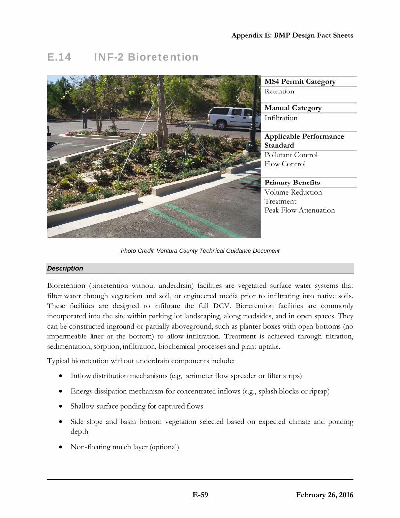
Appendix E: BMP Design Fact Sheets
E-59 February 26, 2016
E.14 INF-2 Bioretention
Photo Credit: Ventura County Technical Guidance Document
Description
Bioretention (bioretention without underdrain) facilities are vegetated surface water systems that filter water through vegetation and soil, or engineered media prior to infiltrating into native soils. These facilities are designed to infiltrate the full DCV. Bioretention facilities are commonly incorporated into the site within parking lot landscaping, along roadsides, and in open spaces. They can be constructed inground or partially aboveground, such as planter boxes with open bottoms (no impermeable liner at the bottom) to allow infiltration. Treatment is achieved through filtration, sedimentation, sorption, infiltration, biochemical processes and plant uptake.
Typical bioretention without underdrain components include:
• Inflow distribution mechanisms (e.g, perimeter flow spreader or filter strips)
• Energy dissipation mechanism for concentrated inflows (e.g., splash blocks or riprap)
• Shallow surface ponding for captured flows
• Side slope and basin bottom vegetation selected based on expected climate and ponding depth
• Non-floating mulch layer (optional)
MS4 Permit Category Retention
Manual Category Infiltration Applicable Performance Standard Pollutant Control Flow Control Primary Benefits Volume Reduction Treatment Peak Flow Attenuation

Appendix E: BMP Design Fact Sheets
E-60 February 26, 2016
• Media layer (planting mix or engineered media) capable of supporting vegetation growth
• Filter course layer consisting of aggregate to prevent the migration of fines into uncompacted native soils or the optional aggregate storage layer
• Optional aggregate storage layer for additional infiltration storage
• Uncompacted native soils at the bottom of the facility
• Overflow structure
Design Adaptations for Project Goals
• Full infiltration BMP for storm water pollutant control. Bioretention can be used as a pollutant control BMP designed to infiltrate runoff from direct rainfall as well as runoff from adjacent tributary areas. Bioretention facilities must be designed with an infiltration storage volume (a function of the ponding, media and aggregate storage volumes) equal to the full DCV and able to meet drawdown time limitations.
• Integrated storm water flow control and pollutant control configuration. Bioretention facilities can be designed to provide flow rate and duration control. This may be accomplished by providing greater infiltration storage with increased surface ponding and/or aggregate storage volume for storm water flow control.

Appendix E: BMP Design Fact Sheets
E-61 February 26, 2016
Typical plan and section view of a Bioretention BMP

Appendix E: BMP Design Fact Sheets
E-62 February 26, 2016
Design Criteria and Considerations
Bioretention must meet the following design criteria. Deviations from the below criteria may be approved at the discretion of County staff if it is determined to be appropriate:
Siting and Design Intent/Rationale
□ Placement observes geotechnical recommendations regarding potential hazards (e.g., slope stability, landslides, liquefaction zones) and setbacks (e.g., slopes, foundations, utilities).
Must not negatively impact existing site geotechnical concerns.
□ Selection and design of BMP is based on infiltration feasibility criteria and appropriate design infiltration rate presented in Appendix C and D.
Must operate as a full infiltration design and must be supported by drainage area and in-situ infiltration rate feasibility findings.
□ Contributing tributary area is ≤ 5 acres (≤ 1 acre preferred).
Bigger BMPs require additional design features for proper performance.
Contributing tributary area greater than 5 acres may be allowed at the discretion of County staff if the following conditions are met: 1) incorporate design features (e.g. flow spreaders) to minimize short circuiting of flows in the BMP and 2) incorporate additional design features requested by County staff for proper performance of the regional BMP.
□ Finish grade of the facility is ≤ 2%. In long bioretention facilities where the potential for internal erosion and channelization exists, the use of check dams is required.
Flatter surfaces reduce erosion and channelization within the facility. Internal check dams reduce velocity and dissipate energy.
Surface Ponding
□ Surface ponding is limited to a 24-hour drawdown time.
24-hour drawdown time is recommended for plant health.
Surface ponding drawdown time greater than 24-hours but less than 96 hours may be allowed at the discretion of County staff if certified by a landscape architect or agronomist.

Appendix E: BMP Design Fact Sheets
E-63 February 26, 2016
Surface Ponding
□ Surface ponding depth is ≥ 6 and ≤ 12 inches.
Surface ponding capacity lowers subsurface storage requirements. Deep surface ponding raises safety concerns.
Surface ponding depth greater than 12 inches (for additional pollutant control or surface outlet structures or flow-control orifices) may be allowed at the discretion of County staff if the following conditions are met: 1) surface ponding depth drawdown time is less than 24 hours; and 2) safety issues and fencing requirements are considered (typically ponding greater than 18” will require a fence and/or flatter side slopes) and 3) potential for elevated clogging risk is considered.
□ A minimum of 2 inches of freeboard is provided.
Freeboard provides room for head over overflow structures and minimizes risk of uncontrolled surface discharge.
□ Side slopes are stabilized with vegetation and are ≥ 3H: 1V.
Gentler side slopes are safer, less prone to erosion, able to establish vegetation more quickly and easier to maintain.
Vegetation
□ Plantings are suitable for the climate and expected ponding depth. A plant list to aid in selection can be found in Appendix E.20.
Plants suited to the climate and ponding depth are more likely to survive.
□ An irrigation system with a connection to water supply is provided as needed.
Seasonal irrigation might be needed to keep plants healthy.
Mulch (Mandatory)
□ A minimum of 3 inches of well-aged, shredded hardwood mulch that has been stockpiled or stored for at least 12 months is provided. Mulch must be non-floating to avoid clogging of overflow structure.
Mulch will suppress weeds and maintain moisture for plant growth. Aging mulch kills pathogens and weed seeds and allows beneficial microbes to multiply.

Appendix E: BMP Design Fact Sheets
E-64 February 26, 2016
Media Layer
□ Media maintains a minimum filtration rate of 5 in/hr over lifetime of facility. A minimum initial filtration rate of 10 in/hr is recommended.
A high filtration rate through the soil mix minimizes clogging potential and allows flows to quickly enter the aggregate storage layer, thereby minimizing bypass.
□
Media is a minimum 18 inches deep, meeting either of these two media specifications:
City of San Diego Low Impact Development Design Manual (page B-18) (July 2011, unless superseded by more recent edition) or County of San Diego Low Impact Development Handbook: Appendix G -Bioretention Soil Specification (June 2014, unless superseded by more recent edition).
A deep media layer provides additional filtration and supports plants with deeper roots.
Standard specifications must be followed.
□ Alternatively, for proprietary designs and custom media mixes not meeting the media specifications contained in the City or County LID Manual, the media meets the pollutant treatment performance criteria in Section F.1.
For non-standard or proprietary designs, compliance with F.1 ensures that adequate treatment performance will be provided.
□ Media surface area is 3% of contributing area times adjusted runoff factor or greater.
Greater surface area to tributary area ratios decrease loading rates per square foot and therefore increase longevity.
Adjusted runoff factor is to account for site design BMPs implemented upstream of the BMP (such as rain barrels, impervious area dispersion, etc.). Refer to Appendix B.2 guidance.
Use Worksheet B.5-1 Line 26 to estimate the minimum surface area required per this criteria.
Filter Course Layer (Optional)
□ A filter course is used to prevent migration of fines through layers of the facility. Filter fabric is not used.
Migration of media can cause clogging of the aggregate storage layer void spaces or subgrade. Filter fabric is more likely to clog.
□ Filter course is washed and free of fines. Washing aggregate will help eliminate fines that could clog the facility and impede infiltration.
Appendix E: BMP Design Fact Sheets
E-65 February 26, 2016
Filter Course Layer (Optional)
□ Filter course calculations assessing suitability for particle migration prevention have been completed.
Gradation relationship between layers can evaluate factors (e.g., bridging, permeability, and uniformity) to determine if particle sizing is appropriate or if an intermediate layer is needed.
Aggregate Storage Layer (Optional)
□
Class 2 Permeable per Caltrans specification 68-1.025 is recommended for the storage layer. Washed, open-graded crushed rock may be used, however a 4-6 inch washed pea gravel filter course layer at the top of the crushed rock is required.
Washing aggregate will help eliminate fines that could clog the aggregate storage layer void spaces or subgrade.
□ Maximum aggregate storage layer depth is determined based on the infiltration storage volume that will infiltrate within a 36-hour drawdown time.
A maximum drawdown time to facilitate provision of adequate storm water storage for the next storm event.
The applicant has an option to use a different drawdown time of up to 120 hours if the volume of the facility is adjusted using the percent capture method in Appendix B.4.1.
Inflow and Overflow Structures
□ Inflow and overflow structures are accessible for inspection and maintenance. Overflow structures must be connected to downstream storm drain system or appropriate discharge point.
Maintenance will prevent clogging and ensure proper operation of the flow control structures.
□ Inflow velocities are limited to 3 ft/s or less or use energy dissipation methods (e.g., riprap, level spreader) for concentrated inflows.
High inflow velocities can cause erosion, scour and/or channeling.
□ Curb cut inlets are at least 12 inches wide, have a 4-6 inch reveal (drop) and an apron and energy dissipation as needed.
Inlets must not restrict flow and apron prevents blockage from vegetation as it grows in. Energy dissipation prevents erosion.

Appendix E: BMP Design Fact Sheets
E-66 February 26, 2016
□ Overflow is safely conveyed to a downstream storm drain system or discharge point. Size overflow structure to pass 100-year peak flow for on-line basins and water quality peak flow for off-line basins.
Planning for overflow lessens the risk of property damage due to flooding.
Conceptual Design and Sizing Approach for Storm Water Pollutant Control Only
To design bioretention for storm water pollutant control only (no flow control required), the following steps should be taken:
1. Verify that siting and design criteria have been met, including placement and basin area requirements, maximum side and finish grade slope, and the recommended media surface area tributary ratio.
2. Calculate the DCV per Appendix B based on expected site design runoff for tributary areas. 3. Use the sizing worksheet to determine if full infiltration of the DCV is achievable based on
the available infiltration storage volume calculated from the bioretention without underdrain footprint area, effective depths for surface ponding, media and aggregate storage layers, and in-situ soil design infiltration rate for a maximum 36-hour drawdown time for the aggregate storage layer (unless percent capture method is used), with surface ponding no greater than a maximum 24-hour drawdown. The drawdown time can be estimated by dividing the average depth of the basin by the design infiltration rate of the underlying soil. Appendix D provides guidance on evaluating a site’s infiltration rate. A generic sizing worksheet is provided in Appendix B.4.
4. Where the DCV cannot be fully infiltrated based on the site or bioretention constraints, an underdrain can be added to the design (use biofiltration with partial retention factsheet).
Conceptual Design and Sizing Approach when Storm Water Flow Control is Applicable
Control of flow rates and/or durations will typically require significant surface ponding and/or aggregate storage volumes, and therefore the following steps should be taken prior to determination of storm water pollutant control design. Pre-development and allowable post-project flow rates and durations must be determined as discussed in Chapter 6 of the manual.
1. Verify that siting and design criteria have been met, including placement requirements, maximum side and finish grade slopes, and the recommended media surface area tributary area ratio. Design for flow control can be achieved using various design configurations.
2. Iteratively determine the facility footprint area, surface ponding and/or aggregate storage layer depth required to provide infiltration storage to reduce flow rates and durations to allowable limits while adhering to the maximum drawdown times for surface ponding and aggregate storage. Flow rates and durations can be controlled using flow splitters that route the appropriate inflow amounts to the bioretention facility and bypass excess flows to the

Appendix E: BMP Design Fact Sheets
E-67 February 26, 2016
downstream storm drain system or discharge point. 3. If bioretention without underdrain facility cannot fully provide the flow rate and duration
control required by the MS4 permit, an upstream or downstream structure with appropriate storage volume such as an underground vault can be used to provide additional control.
4. After bioretention without underdrain BMPs have been designed to meet flow control requirements, calculations must be completed to verify if storm water pollutant control requirements to treat the DCV have been met.

Appendix E: BMP Design Fact Sheets
E-68 February 26, 2016
This page was left intentionally blank.

Appendix E: BMP Design Fact Sheets
E-69 February 26, 2016
E.15 INF-3 Permeable Pavement (Pollutant Control)
Location: Kellogg Park, San Diego, California
Description
Permeable pavement is pavement that allows for percolation through void spaces in the pavement surface into subsurface layers. The subsurface layers are designed to provide storage of storm water runoff so that outflows, primarily via infiltration into subgrade soils or release to the downstream conveyance system, can be at controlled rates. Varying levels of storm water treatment and flow control can be provided depending on the size of the permeable pavement system relative to its drainage area, the underlying infiltration rates, and the configuration of outflow controls. Pollutant control permeable pavement is designed to receive runoff from a larger tributary area than site design permeable pavement (see SD-D). Pollutant control is provided via infiltration, filtration, sorption, sedimentation, and biodegradation processes. Permeable pavements proposed as a retention or partial retention BMP should not have an impermeable liner.
Typical permeable pavement components include, from top to bottom:
• Permeable surface layer
• Bedding layer for permeable surface
• Aggregate storage layer with optional underdrain(s)
MS4 Permit Category Retention Flow-thru Treatment Control Manual Category Infiltration Flow-thru Treatment Control Applicable Performance Standard Pollutant Control Flow Control Primary Benefits Volume Reduction Peak Flow Attenuation

Appendix E: BMP Design Fact Sheets
E-70 February 26, 2016
• Optional final filter course layer over uncompacted existing subgrade
Typical plan and Section view of a Permeable Pavement BMP

Appendix E: BMP Design Fact Sheets
E-71 February 26, 2016
Subcategories of permeable pavement include modular paver units or paver blocks, pervious concrete, porous asphalt, and turf pavers. These subcategory variations differ in the material used for the permeable surface layer but have similar functions and characteristics below this layer.
Design Adaptations for Project Goals
Site design BMP to reduce impervious area and DCV. See site design option SD-D.
Full infiltration BMP for storm water pollutant control. Permeable pavement without an underdrain and without impermeable liners can be used as a pollutant control BMP, designed to infiltrate runoff from direct rainfall as well as runoff from adjacent areas that are tributary to the pavement. The system must be designed with an infiltration storage volume (a function of the aggregate storage volume) equal to the full DCV and able to meet drawdown time limitations.
Partial infiltration BMP with flow-thru treatment for storm water pollutant control. Permeable pavement can be designed so that a portion of the DCV is infiltrated by providing an underdrain with infiltration storage below the underdrain invert. The infiltration storage depth should be determined by the volume that can be reliably infiltrated within drawdown time limitations. Water discharged through the underdrain is considered flow-thru treatment and is not considered biofiltration treatment. Storage provided above the underdrain invert is included in the flow-thru treatment volume.
Flow-thru treatment BMP for storm water pollutant control. The system may be lined and/or installed over impermeable native soils with an underdrain provided at the bottom to carry away filtered runoff. Water quality treatment is provided via unit treatment processes other than infiltration. This configuration is considered to provide flow-thru treatment, not biofiltration treatment. Significant aggregate storage provided above the underdrain invert can provide detention storage, which can be controlled via inclusion of an orifice in an outlet structure at the downstream end of the underdrain. PDPs have the option to add saturated storage to the flow-thru configuration in order to reduce the DCV that the BMP is required to treat. Saturated storage can be added to this design by including an upturned elbow installed at the downstream end of the underdrain or via an internal weir structure designed to maintain a specific water level elevation. The DCV can be reduced by the amount of saturated storage provided.
Integrated storm water flow control and pollutant control configuration. With any of the above configurations, the system can be designed to provide flow rate and duration control. This may include having a deeper aggregate storage layer that allows for significant detention storage above the underdrain, which can be further controlled via inclusion of an outlet structure at the downstream end of the underdrain.

Appendix E: BMP Design Fact Sheets
E-72 February 26, 2016
Design Criteria and Considerations
Permeable pavements must meet the following design criteria. Deviations from the below criteria may be approved at the discretion of County staff if it is determined to be appropriate:
Siting and Design Intent/Rationale
□ Placement observes geotechnical recommendations regarding potential hazards (e.g., slope stability, landslides, liquefaction zones) and setbacks (e.g., slopes, foundations, utilities).
Must not negatively impact existing site geotechnical concerns.
□ Selection must be based on infiltration feasibility criteria.
Full or partial infiltration designs must be supported by drainage area feasibility findings.
□ An impermeable liner or other hydraulic restriction layer is included if site constraints indicate that infiltration should not be allowed.
Lining prevents storm water from impacting groundwater and/or sensitive environmental or geotechnical features. Incidental infiltration, when allowable, can aid in pollutant removal and groundwater recharge.
□ Permeable pavement is not placed in an area with significant overhanging trees or other vegetation.
Leaves and organic debris can clog the pavement surface.
□ For pollutant control permeable pavement, the ratio of the total drainage area (including the permeable pavement) to the permeable pavement should not exceed 4:1.
Higher ratios increase the potential for clogging but may be acceptable for relatively clean tributary areas.
□ Finish grade of the permeable pavement has a slope ≤ 5%.
Flatter surfaces facilitate increased runoff capture.
□ Minimum depth to groundwater and bedrock ≥ 10 ft.
A minimum separation facilitates infiltration and lessens the risk of negative groundwater impacts.
□ Contributing tributary area includes effective sediment source control and/or pretreatment measures such as raised curbed or grass filter strips.
Sediment can clog the pavement surface.

Appendix E: BMP Design Fact Sheets
E-73 February 26, 2016
Siting and Design Intent/Rationale
□ Direct discharges to permeable pavement are only from downspouts carrying “clean” roof runoff that are equipped with filters to remove gross solids.
Roof runoff typically carries less sediment than runoff from other impervious surfaces and is less likely to clog the pavement surface.
Permeable Surface Layer
□ Permeable surface layer type is appropriately chosen based on pavement use and expected vehicular loading.
Pavement may wear more quickly if not durable for expected loads or frequencies.
□ Permeable surface layer type is appropriate for expected pedestrian traffic.
Expected demographic and accessibility needs (e.g., adults, children, seniors, runners, high-heeled shoes, wheelchairs, strollers, bikes) requires selection of appropriate surface layer type that will not impede pedestrian needs.

Appendix E: BMP Design Fact Sheets
E-74 February 26, 2016
Bedding Layer for Permeable Surface
□ Bedding thickness and material is appropriate for the chosen permeable surface layer type.
Porous asphalt requires a 2- to 4-inch layer of asphalt and a 1- to 2-inch layer of choker course (single-sized crushed aggregate, one-half inch) to stabilize the surface.
Pervious concrete also requires an aggregate course of clean gravel or crushed stone with a minimum amount of fines.
Permeable Interlocking Concrete Paver requires 1 or 2 inches of sand or No. 8 aggregate to allow for leveling of the paver blocks.
Similar to Permeable Interlocking Concrete Paver, plastic grid systems also require a 1- to 2-inch bedding course of either gravel or sand.
For Permeable Interlocking Concrete Paver and plastic grid systems, if sand is used, a geotextile should be used between the sand course and the reservoir media to prevent the sand from migrating into the stone media.
□ Aggregate used for bedding layer is washed prior to placement.
Washing aggregate will help eliminate fines that could clog the permeable pavement system aggregate storage layer void spaces or underdrain.
Media Layer (Optional) –used between bedding layer and aggregate storage layer to provide pollutant treatment control
□ The pollutant removal performance of the media layer is documented by the applicant.
Media used for BMP design should be shown via research or testing to be appropriate for expected pollutants of concern and flow rates.
□ A filter course is provided to separate the media layer from the aggregate storage layer.
Migration of media can cause clogging of the aggregate storage layer void spaces or underdrain.

Appendix E: BMP Design Fact Sheets
E-75 February 26, 2016
Media Layer (Optional) –used between bedding layer and aggregate storage layer to provide pollutant treatment control
□ If a filter course is used, calculations assessing suitability for particle migration prevention have been completed.
Gradation relationship between layers can evaluate factors (e.g., bridging, permeability, and uniformity) to determine if particle sizing is appropriate or if an intermediate layer is needed.
□ Consult permeable pavement manufacturer to verify that media layer provides required structural support.
Media must not compromise the structural integrity or intended uses of the permeable pavement surface.
Aggregate Storage Layer
□ Aggregate used for the aggregate storage layer is washed and free of fines.
Washing aggregate will help eliminate fines that could clog aggregate storage layer void spaces or underdrain.
□ Minimum layer depth is 6 inches and for infiltration designs, the maximum depth is determined based on the infiltration storage volume that will infiltrate within a 36-hour drawdown time.
A minimum depth of aggregate provides structural stability for expected pavement loads.
The applicant has an option to use a different drawdown time of up to 120 hours if the volume of the facility is adjusted using the percent capture method in Appendix B.4.1
Underdrain and Outflow Structures
□ Underdrains and outflow structures, if used, are accessible for inspection and maintenance.
Maintenance will improve the performance and extend the life of the permeable pavement system.
□ Underdrain outlet elevation should be a minimum of 3 inches above the bottom elevation of the aggregate storage layer.
A minimal separation from subgrade or the liner lessens the risk of fines entering the underdrain and can improve hydraulic performance by allowing perforations to remain unblocked.
□ Minimum underdrain diameter is 6 inches. Smaller diameter underdrains are prone to clogging.
□ Underdrains are made of slotted, PVC pipe conforming to ASTM D 3034 or equivalent or corrugated, HDPE pipe conforming to AASHTO 252M or equivalent.
Slotted underdrains provide greater intake capacity, clog resistant drainage, and reduced entrance velocity into the pipe, thereby reducing the chances of solids migration.

Appendix E: BMP Design Fact Sheets
E-76 February 26, 2016
Filter Course (Optional)
□ Filter course is washed and free of fines. Washing aggregate will help eliminate fines that could clog subgrade and impede infiltration.
Conceptual Design and Sizing Approach for Site Design
1. Determine the areas where permeable pavement can be used in the site design to replace traditional pavement to reduce the impervious area and DCV. These permeable pavement areas can be credited toward reducing runoff generated through representation in storm water calculations as pervious, not impervious, areas but are not credited for storm water pollutant control. These permeable pavement areas should be designed as self-retaining with the appropriate tributary area ratio identified in the design criteria.
2. Calculate the DCV per Appendix B, taking into account reduced runoff from self-retaining permeable pavement areas.
Conceptual Design and Sizing Approach for Storm Water Pollutant Control Only
To design permeable pavement for storm water pollutant control only (no flow control required), the following steps should be taken:
1. Verify that siting and design criteria have been met, including placement requirements, maximum finish grade slope, and the recommended tributary area ratio for non-self-retaining permeable pavement. If infiltration is infeasible, the permeable pavement can be designed as flow-thru treatment per the sizing worksheet. If infiltration is feasible, calculations should follow the remaining design steps.
2. Calculate the DCV per Appendix B based on expected site design runoff for tributary areas.
3. Use the sizing worksheet to determine if full or partial infiltration of the DCV is achievable based on the available infiltration storage volume calculated from the permeable pavement footprint, aggregate storage layer depth, and in-situ soil design infiltration rate for a maximum 36-hour drawdown time. The applicant has an option to use a different drawdown time up to 120 hours if the volume of the facility is adjusted using the percent capture method in Appendix B.4.1.
4. Where the DCV cannot be fully infiltrated based on the site or permeable pavement constraints, an underdrain must be incorporated above the infiltration storage to carry away runoff that exceeds the infiltration storage capacity.
5. The remaining DCV to be treated should be calculated for use in sizing downstream BMP(s).

Appendix E: BMP Design Fact Sheets
E-77 February 26, 2016
Conceptual Design and Sizing Approach when Storm Water Flow Control is Applicable
Control of flow rates and/or durations will typically require significant aggregate storage volumes, and therefore the following steps should be taken prior to determination of storm water pollutant control design. Pre-development and allowable post-project flow rates and durations should be determined as discussed in Chapter 6 of the manual.
1. Verify that siting and design criteria have been met, including placement requirements, maximum finish grade slope, and the recommended tributary area ratio for non-self-retaining permeable pavement. Design for flow control can be achieving using various design configurations, but a flow-thru treatment design will typically require a greater aggregate storage layer volume than designs which allow for full or partial infiltration of the DCV.
2. Iteratively determine the area and aggregate storage layer depth required to provide infiltration and/or detention storage to reduce flow rates and durations to allowable limits. Flow rates and durations can be controlled from detention storage by altering outlet structure orifice size(s) and/or water control levels. Multi-level orifices can be used within an outlet structure to control the full range of flows.
3. If the permeable pavement system cannot fully provide the flow rate and duration control required by this manual, a downstream structure with sufficient storage volume such as an underground vault can be used to provide remaining controls.
4. After permeable pavement has been designed to meet flow control requirements, calculations must be completed to verify if storm water pollutant control requirements to treat the DCV have been met.

Appendix E: BMP Design Fact Sheets
E-78 February 26, 2016
This page was left intentionally blank.

Appendix E: BMP Design Fact Sheets
E-79 February 26, 2016
E.16 INF-4 Dry Wells
Source: Cal/EPA Fact Sheet on Dry Wells
Description
Dry wells are typically designed as gravity-fed pits lined with perforated casing and often backfilled with gravel or stone. Dry wells are intended to penetrate layers of poorly infiltrating soils, such as clays, allowing infiltration into deeper permeable layers. Dry wells can reduce storm water runoff while increasing groundwater recharge. It is recommended that dry wells be used in conjunction with low impact development (LID) practices (or pretreatment) to help reduce potential contaminants to groundwater and aquatic ecosystem. Pretreatment effectiveness is contingent upon proper maintenance. With proper design and maintenance, dry wells not only aid in stormwater runoff reduction, but they can also increase groundwater recharge.
Design Adaptations for Project Goals
Full infiltration BMP for storm water pollutant control. Dry wells can be used as a pollutant control BMP, designed to infiltrate runoff from direct rainfall as well as runoff from adjacent areas that are tributary to the pavement. Dry wells must be designed with an infiltration storage volume equal to the full DCV and able to meet drawdown time limitations.
Integrated storm water flow control and pollutant control configuration. Dry wells can be designed to provide flow rate and duration control. This may be accomplished by providing greater infiltration storage
Criteria and Considerations for Use of a Dry Wells as Infiltration BMP
In general, a careful site evaluation conducted by a registered civil engineer and a geologist/geotechnical engineer should be made to determine if the use of a dry well is suitable at any particular location
MS4 Permit Category Retention
Manual Category Infiltration Applicable Performance Standard Pollutant Control Flow Control Primary Benefits Volume Reduction

Appendix E: BMP Design Fact Sheets
E-80 February 26, 2016
A dry well may be acceptable as an “infiltration BMP” if it meets ALL the following criteria:
• The BMP meets the minimum geotechnical and groundwater investigation requirements listed in Appendix C; and
• The BMP is evaluated by approved infiltration rate assessment methods presented in Appendix D; and
• Implements an appropriate Low Impact Development (LID) practice / pretreatment BMP (refer to Appendix B.6.2 for selection); and
• Dry wells serving lots other than single-family homes are registered with the US EPA.
In designing a dry well, the following items should be considered:
• Depth of dry well – The EPA currently encourages that the well “should not be constructed deeper than the seasonal high water table”. As water begins to percolate into an aquifer, it requires a certain holding time in order to filter out contaminants before reaching the water table. This would need to be addressed by a professional geologist/geotechnical engineer.
• Geology – Theoretically the well would be dug through an area of low permeability and into an area that would allow the movement of water into the aquifer. Also, the type of geology and its ability to act as a conduit to the aquifer system would need to be addressed. This assessment would need to be made by a professional geologist/geotechnical engineer (Note: While some areas are conducive to this, vast areas of the County of San Diego have geological conditions not conducive for dry wells).
• Grading – The use of a dry well without the proper grading and back up storm drain system might pose a problem with the ponding of runoff due to the dry well’s limited storage capacity and the time it would take to discharge water into the aquifer system. This assessment would need to be made by a professional civil engineer.
• Routine maintenance – Pretreatment effectiveness is contingent upon proper maintenance. Routine maintenance should be provided in order to keep a dry well free of trash/debris, sediments, oil and grease, etc.
• Potential contamination – It is recommended that dry wells be used in conjunction with low impact development (LID) practices (or pretreatment BMPs) to help reduce potential contaminants to groundwater and aquatic ecosystem. Note: The County of San Diego Department of Environmental Health may be able to provide further input.
Note: As indicated on the Cal/EPA Fact Sheet on Dry Wells, there are currently no uniform state regulations or guidelines on dry wells in California. The purpose of this fact sheet is to help explain the role of dry wells in meeting infiltration requirements. Therefore, this fact sheet does not describe specific design criteria like the other fact sheets in this manual. The County of San Diego may develop specific design criteria and include in this fact sheet at a future time.
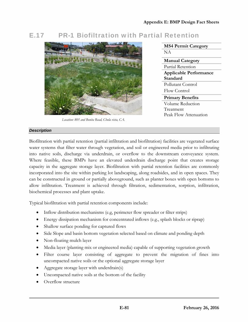
Appendix E: BMP Design Fact Sheets
E-81 February 26, 2016
E.17 PR-1 Biofiltration with Partial Retention
Location: 805 and Bonita Road, Chula vista, CA.
Description
Biofiltration with partial retention (partial infiltration and biofiltration) facilities are vegetated surface water systems that filter water through vegetation, and soil or engineered media prior to infiltrating into native soils, discharge via underdrain, or overflow to the downstream conveyance system. Where feasible, these BMPs have an elevated underdrain discharge point that creates storage capacity in the aggregate storage layer. Biofiltration with partial retention facilities are commonly incorporated into the site within parking lot landscaping, along roadsides, and in open spaces. They can be constructed in ground or partially aboveground, such as planter boxes with open bottoms to allow infiltration. Treatment is achieved through filtration, sedimentation, sorption, infiltration, biochemical processes and plant uptake.
Typical biofiltration with partial retention components include:
• Inflow distribution mechanisms (e.g, perimeter flow spreader or filter strips) • Energy dissipation mechanism for concentrated inflows (e.g., splash blocks or riprap) • Shallow surface ponding for captured flows • Side Slope and basin bottom vegetation selected based on climate and ponding depth • Non-floating mulch layer • Media layer (planting mix or engineered media) capable of supporting vegetation growth • Filter course layer consisting of aggregate to prevent the migration of fines into
uncompacted native soils or the optional aggregate storage layer • Aggregate storage layer with underdrain(s) • Uncompacted native soils at the bottom of the facility • Overflow structure
MS4 Permit CategoryNA
Manual Category Partial Retention Applicable Performance Standard Pollutant Control Flow Control Primary Benefits Volume Reduction Treatment Peak Flow Attenuation

Appendix E: BMP Design Fact Sheets
E-82 February 26, 2016
Typical plan and Section view of a Biofiltration with Partial Retention BMP

Appendix E: BMP Design Fact Sheets
E-83 February 26, 2016
Design Adaptations for Project Goals
Partial infiltration BMP with biofiltration treatment for storm water pollutant control. Biofiltration with partial retention can be designed so that a portion of the DCV is infiltrated by providing infiltration storage below the underdrain invert. The infiltration storage depth should be determined by the volume that can be reliably infiltrated within drawdown time limitations. Water discharged through the underdrain is considered biofiltration treatment. Storage provided above the underdrain within surface ponding, media, and aggregate storage is included in the biofiltration treatment volume.
Integrated storm water flow control and pollutant control configuration. The system can be designed to provide flow rate and duration control by primarily providing increased surface ponding and/or having a deeper aggregate storage layer. This will allow for significant detention storage, which can be controlled via inclusion of an orifice in an outlet structure at the downstream end of the underdrain.
Design Criteria and Considerations
Biofiltration with partial retention must meet the following design criteria and considerations. Deviations from the below criteria may be approved at the discretion of County staff if it is determined to be appropriate:
Siting and Design Intent/Rationale
□ Placement observes geotechnical recommendations regarding potential hazards (e.g., slope stability, landslides, liquefaction zones) and setbacks (e.g., slopes, foundations, utilities).
Must not negatively impact existing site geotechnical concerns.
□ Selection and design of basin is based on infiltration feasibility criteria and appropriate design infiltration rate (See Appendix C and D).
Must operate as a partial infiltration design and must be supported by drainage area and in-situ infiltration rate feasibility findings.
Appendix E: BMP Design Fact Sheets
E-84 February 26, 2016
Siting and Design Intent/Rationale
□ Contributing tributary area must be ≤ 5 acres (≤ 1 acre preferred).
Bigger BMPs require additional design features for proper performance.
Contributing tributary area greater than 5 acres may be allowed at the discretion of County staff if the following conditions are met: 1) incorporate design features (e.g. flow spreaders) to minimize short circuiting of flows in the BMP and 2) incorporate additional design features requested by County staff for proper performance of the regional BMP.
□ Finish grade of the facility is ≤ 2%. Flatter surfaces reduce erosion and channelization within the facility.
Surface Ponding
□ Surface ponding is limited to a 24-hour drawdown time.
Surface ponding limited to 24 hours for plant health.
□ Surface ponding depth is ≥ 6 and ≤ 12 inches.
Surface ponding capacity lowers subsurface storage requirements. Deep surface ponding raises safety concerns.
Surface ponding depth greater than 12 inches (for additional pollutant control or surface outlet structures or flow-control orifices) may be allowed at the discretion of County staff if the following conditions are met: 1) surface ponding depth drawdown time is less than 24 hours; and 2) safety issues and fencing requirements are considered (typically ponding greater than 18” will require a fence and/or flatter side slopes) and 3) potential for elevated clogging risk is considered.
□ A minimum of 2 inches of freeboard is provided.
Freeboard provides room for head over overflow structures and minimizes risk of uncontrolled surface discharge.
□ Side slopes are stabilized with vegetation and are = 3H:1V or shallower.
Gentler side slopes are safer, less prone to erosion, able to establish vegetation more quickly and easier to maintain.

Appendix E: BMP Design Fact Sheets
E-85 February 26, 2016
Vegetation
□ Plantings are suitable for the climate and expected ponding depth. A plant list to aid in selection can be found in Appendix E.20
Plants suited to the climate and ponding depth are more likely to survive.
□ An irrigation system with a connection to water supply should be provided as needed.
Seasonal irrigation might be needed to keep plants healthy.
Mulch (Mandatory)
□ A minimum of 3 inches of well-aged, shredded hardwood mulch that has been stockpiled or stored for at least 12 months is provided. Mulch must be non-floating to avoid clogging of overflow structure.
Mulch will suppress weeds and maintain moisture for plant growth. Aging mulch kills pathogens and weed seeds and allows the beneficial microbes to multiply.
Media Layer
□ Media maintains a minimum filtration rate of 5 in/hr over lifetime of facility. An initial filtration rate of 8 to 12 in/hr is recommended to allow for clogging over time; the initial filtration rate should not exceed 12 inches per hour.
A filtration rate of at least 5 inches per hour allows soil to drain between events, and allows flows to relatively quickly enter the aggregate storage layer, thereby minimizing bypass. The initial rate should be higher than long term target rate to account for clogging over time. However an excessively high initial rate can have a negative impact on treatment performance, therefore an upper limit is needed.

Appendix E: BMP Design Fact Sheets
E-86 February 26, 2016
Media Layer
□
Media is a minimum 18 inches deep, meeting either of these two media specifications:
City of San Diego Storm Water Standards Appendix F (February 2016, unless superseded by more recent edition) or County of San Diego Low Impact Development Handbook: Appendix G -Bioretention Soil Specification (June 2014, unless superseded by more recent edition).
Alternatively, for proprietary designs and custom media mixes not meeting the media specifications contained in the 2016 City Storm Water Standards or County LID Manual, the media meets the pollutant treatment performance criteria in Section F.1.
A deep media layer provides additional filtration and supports plants with deeper roots.
Standard specifications must be followed.
For non-standard or proprietary designs, compliance with Appendix F.1 ensures that adequate treatment performance will be provided.
□ Media surface area is 3% of contributing area times adjusted runoff factor or greater. Unless demonstrated that the BMP surface area can be smaller than 3%.
Greater surface area to tributary area ratios: a) maximizes volume retention as required by the MS4 Permit and b) decrease loading rates per square foot and therefore increase longevity.
Adjusted runoff factor is to account for site design BMPs implemented upstream of the BMP (such as rain barrels, impervious area dispersion, etc.). Refer to Appendix B.2 guidance.
Use Worksheet B.5-1 Line 26 to estimate the minimum surface area required per this criteria.
□ Where receiving waters are impaired or have a TMDL for nutrients, the system is designed with nutrient sensitive media design (see fact sheet BF-2).
Potential for pollutant export is partly a function of media composition; media design must minimize potential for export of nutrients, particularly where receiving waters are impaired for nutrients.

Appendix E: BMP Design Fact Sheets
E-87 February 26, 2016
Filter Course Layer
□ A filter course is used to prevent migration of fines through layers of the facility. Filter fabric is not used.
Migration of media can cause clogging of the aggregate storage layer void spaces or subgrade. Filter fabric is more likely to clog.
□ Filter course is washed and free of fines. Washing aggregate will help eliminate fines that could clog the facility
□ Filter course calculations assessing suitability for particle migration prevention have been completed.
Gradation relationship between layers can evaluate factors (e.g., bridging, permeability, and uniformity) to determine if particle sizing is appropriate or if an intermediate layer is needed.
Aggregate Storage Layer
□
Class 2 Permeable per Caltrans specification 68-1.025 is recommended for the storage layer. Washed, open-graded crushed rock may be used, however a 4-6 inch washed pea gravel filter course layer at the top of the crushed rock is required.
Washing aggregate will help eliminate fines that could clog the aggregate storage layer void spaces or subgrade.
□ Maximum aggregate storage layer depth below the underdrain invert is determined based on the infiltration storage volume that will infiltrate within a 48-hour drawdown time.
A maximum drawdown time is needed for vector control and to facilitate providing storm water storage for the next storm event.
Inflow, Underdrain, and Outflow Structures
□ Inflow, underdrains and outflow structures are accessible for inspection and maintenance.
Maintenance will prevent clogging and ensure proper operation of the flow control structures.
□ Inflow velocities are limited to 3 ft/s or less or use energy dissipation methods. (e.g., riprap, level spreader) for concentrated inflows.
High inflow velocities can cause erosion, scour and/or channeling.
□ Curb cut inlets are at least 12 inches wide, have a 4-6 inch reveal (drop) and an apron and energy dissipation as needed.
Inlets must not restrict flow and apron prevents blockage from vegetation as it grows in. Energy dissipation prevents erosion.

Appendix E: BMP Design Fact Sheets
E-88 February 26, 2016
Inflow, Underdrain, and Outflow Structures
□ Underdrain outlet elevation should be a minimum of 3 inches above the bottom elevation of the aggregate storage layer.
A minimal separation from subgrade or the liner lessens the risk of fines entering the underdrain and can improve hydraulic performance by allowing perforations to remain unblocked.
□ Minimum underdrain diameter is 6 inches. Smaller diameter underdrains are prone to clogging.
□ Underdrains are made of slotted, PVC pipe conforming to ASTM D 3034 or equivalent or corrugated, HDPE pipe conforming to AASHTO 252M or equivalent.
Slotted underdrains provide greater intake capacity, clog resistant drainage, and reduced entrance velocity into the pipe, thereby reducing the chances of solids migration.
□ An underdrain cleanout with a minimum 6-inch diameter and lockable cap is placed every 250 to 300 feet as required based on underdrain length.
Properly spaced cleanouts will facilitate underdrain maintenance.
□ Overflow is safely conveyed to a downstream storm drain system or discharge point. Size overflow structure to pass 100-year peak flow for on-line infiltration basins and water quality peak flow for off-line basins.
Planning for overflow lessens the risk of property damage due to flooding.
Nutrient Sensitive Media Design
To design biofiltration with partial retention with underdrain for storm water pollutant control only (no flow control required), the following steps should be taken:
Conceptual Design and Sizing Approach for Storm Water Pollutant Control Only
To design biofiltration with partial retention and an underdrain for storm water pollutant control only (no flow control required), the following steps should be taken:
1. Verify that siting and design criteria have been met, including placement requirements, contributing tributary area, maximum side and finish grade slopes, and the recommended media surface area tributary ratio.
2. Calculate the DCV per Appendix B based on expected site design runoff for tributary areas. 3. Generalized sizing procedure is presented in Appendix B.5. The surface ponding should be
verified to have a maximum 24-hour drawdown time.

Appendix E: BMP Design Fact Sheets
E-89 February 26, 2016
Conceptual Design and Sizing Approach when Storm Water Flow Control is Applicable
Control of flow rates and/or durations will typically require significant surface ponding and/or aggregate storage volumes, and therefore the following steps should be taken prior to determination of storm water pollutant control design. Pre-development and allowable post-project flow rates and durations should be determined as discussed in Chapter 6 of the manual.
1. Verify that siting and design criteria have been met, including placement requirements, contributing tributary area, maximum side and finish grade slopes, and the recommended media surface area tributary ratio.
2. Iteratively determine the facility footprint area, surface ponding and/or aggregate storage layer depth required to provide detention and/or infiltration storage to reduce flow rates and durations to allowable limits. Flow rates and durations can be controlled from detention storage by altering outlet structure orifice size(s) and/or water control levels. Multi-level orifices can be used within an outlet structure to control the full range of flows.
3. If biofiltration with partial retention cannot fully provide the flow rate and duration control required by this manual, an upstream or downstream structure with significant storage volume such as an underground vault can be used to provide remaining controls.
4. After biofiltration with partial retention has been designed to meet flow control requirements, calculations must be completed to verify if storm water pollutant control requirements to treat the DCV have been met.

Appendix E: BMP Design Fact Sheets
E-90 February 26, 2016
This page was left intentionally blank.
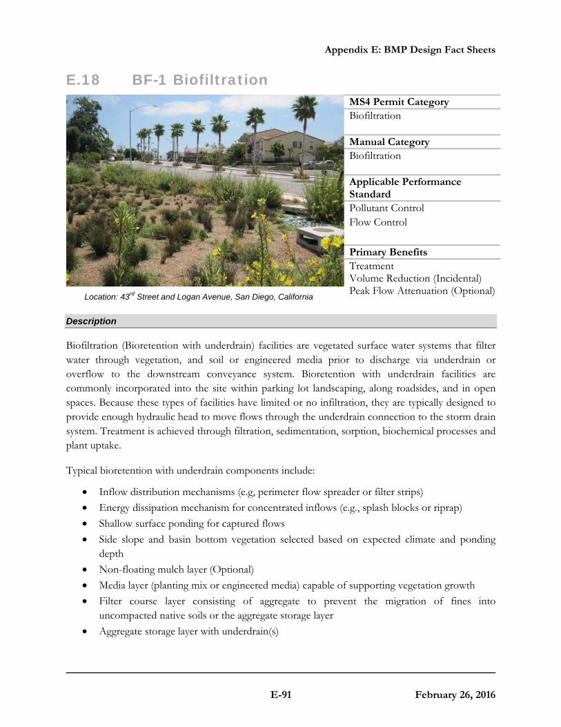
Appendix E: BMP Design Fact Sheets
E-91 February 26, 2016
E.18 BF-1 Biofiltration
Location: 43rd Street and Logan Avenue, San Diego, California
Description
Biofiltration (Bioretention with underdrain) facilities are vegetated surface water systems that filter water through vegetation, and soil or engineered media prior to discharge via underdrain or overflow to the downstream conveyance system. Bioretention with underdrain facilities are commonly incorporated into the site within parking lot landscaping, along roadsides, and in open spaces. Because these types of facilities have limited or no infiltration, they are typically designed to provide enough hydraulic head to move flows through the underdrain connection to the storm drain system. Treatment is achieved through filtration, sedimentation, sorption, biochemical processes and plant uptake.
Typical bioretention with underdrain components include:
• Inflow distribution mechanisms (e.g, perimeter flow spreader or filter strips) • Energy dissipation mechanism for concentrated inflows (e.g., splash blocks or riprap) • Shallow surface ponding for captured flows • Side slope and basin bottom vegetation selected based on expected climate and ponding
depth • Non-floating mulch layer (Optional) • Media layer (planting mix or engineered media) capable of supporting vegetation growth • Filter course layer consisting of aggregate to prevent the migration of fines into
uncompacted native soils or the aggregate storage layer • Aggregate storage layer with underdrain(s)
MS4 Permit Category Biofiltration Manual Category Biofiltration Applicable Performance Standard Pollutant Control Flow Control Primary Benefits Treatment Volume Reduction (Incidental) Peak Flow Attenuation (Optional)

Appendix E: BMP Design Fact Sheets
E-92 February 26, 2016
• Impermeable liner or uncompacted native soils at the bottom of the facility • Overflow structure

Appendix E: BMP Design Fact Sheets
E-93 February 26, 2016
Typical plan and Section view of a Biofiltration BMP
Design Adaptations for Project Goals
Biofiltration Treatment BMP for storm water pollutant control. The system is lined or un-lined to provide incidental infiltration, and an underdrain is provided at the bottom to carry away filtered runoff. This configuration is considered to provide biofiltration treatment via flow through the media layer. Storage provided above the underdrain within surface ponding, media, and aggregate storage is considered included in the biofiltration treatment volume. Saturated storage within the aggregate storage layer can be added to this design by raising the underdrain above the bottom of the aggregate storage layer or via an internal weir structure designed to maintain a specific water level elevation.
Integrated storm water flow control and pollutant control configuration. The system can be designed to provide flow rate and duration control by primarily providing increased surface ponding and/or having a deeper aggregate storage layer above the underdrain. This will allow for significant detention storage, which can be controlled via inclusion of an outlet structure at the downstream end of the underdrain.
Design Criteria and Considerations
Bioretention with underdrain must meet the following design criteria. Deviations from the below criteria may be approved at the discretion of County staff if it is determined to be appropriate:
Siting and Design Intent/Rationale
□ Placement observes geotechnical recommendations regarding potential hazards (e.g., slope stability, landslides, liquefaction zones) and setbacks (e.g., slopes, foundations, utilities).
Must not negatively impact existing site geotechnical concerns.
□ An impermeable liner or other hydraulic restriction layer is included if site constraints indicate that infiltration or lateral flows should not be allowed.
Lining prevents storm water from impacting groundwater and/or sensitive environmental or geotechnical features. Incidental infiltration, when allowable, can aid in pollutant removal and groundwater recharge.
Appendix E: BMP Design Fact Sheets
E-94 February 26, 2016
Siting and Design Intent/Rationale
□ Contributing tributary area must be ≤ 5 acres (≤ 1 acre preferred).
Bigger BMPs require additional design features for proper performance.
Contributing tributary area greater than 5 acres may be allowed at the discretion of County staff if the following conditions are met: 1) incorporate design features (e.g. flow spreaders) to minimize short circuiting of flows in the BMP and 2) incorporate additional design features requested by County staff for proper performance of the regional BMP.
□ Finish grade of the facility is ≤ 2%. Flatter surfaces reduce erosion and channelization within the facility.
Surface Ponding
□ Surface ponding is limited to a 24-hour drawdown time.
Surface ponding limited to 24 hour for plant health. Surface ponding drawdown time greater than 24-hours but less than 96 hours may be allowed at the discretion of County staff if certified by a landscape architect or agronomist.
□ Surface ponding depth is ≥ 6 and ≤ 12 inches.
Surface ponding capacity lowers subsurface storage requirements. Deep surface ponding raises safety concerns.
Surface ponding depth greater than 12 inches (for additional pollutant control or surface outlet structures or flow-control orifices) may be allowed at the discretion of County staff if the following conditions are met: 1) surface ponding depth drawdown time is less than 24 hours; and 2) safety issues and fencing requirements are considered (typically ponding greater than 18” will require a fence and/or flatter side slopes) and 3) potential for elevated clogging risk is considered.
□ A minimum of 2 inches of freeboard is provided.
Freeboard provides room for head over overflow structures and minimizes risk of uncontrolled surface discharge.

Appendix E: BMP Design Fact Sheets
E-95 February 26, 2016
Surface Ponding
□ Side slopes are stabilized with vegetation and are = 3H:1V or shallower.
Gentler side slopes are safer, less prone to erosion, able to establish vegetation more quickly and easier to maintain.
Vegetation
□ Plantings are suitable for the climate and expected ponding depth. A plant list to aid in selection can be found in Appendix E.20.
Plants suited to the climate and ponding depth are more likely to survive.
□ An irrigation system with a connection to water supply should be provided as needed.
Seasonal irrigation might be needed to keep plants healthy.
Mulch (Mandatory)
□ A minimum of 3 inches of well-aged, shredded hardwood mulch that has been stockpiled or stored for at least 12 months is provided.
Mulch will suppress weeds and maintain moisture for plant growth. Aging mulch kills pathogens and weed seeds and allows the beneficial microbes to multiply.
Media Layer
□ Media maintains a minimum filtration rate of 5 in/hr over lifetime of facility. An initial filtration rate of 8 to 12 in/hr is recommended to allow for clogging over time; the initial filtration rate should not exceed 12 inches per hour.
A filtration rate of at least 5 inches per hour allows soil to drain between events. The initial rate should be higher than long term target rate to account for clogging over time. However an excessively high initial rate can have a negative impact on treatment performance, therefore an upper limit is needed.

Appendix E: BMP Design Fact Sheets
E-96 February 26, 2016
Media Layer
□
Media is a minimum 18 inches deep, meeting either of these two media specifications:
City of San Diego Storm Water Standards Appendix F (February 2016, unless superseded by more recent edition) or County of San Diego Low Impact Development Handbook: Appendix G -Bioretention Soil Specification (June 2014, unless superseded by more recent edition).
Alternatively, for proprietary designs and custom media mixes not meeting the media specifications contained in the 2016 City Storm Water Standards or County LID Manual, the media meets the pollutant treatment performance criteria in Section F.1.
A deep media layer provides additional filtration and supports plants with deeper roots.
Standard specifications must be followed.
For non-standard or proprietary designs, compliance with F.1 ensures that adequate treatment performance will be provided.
□ Media surface area is 3% of contributing area times adjusted runoff factor or greater. Unless demonstrated that the BMP surface area can be smaller than 3%.
Greater surface area to tributary area ratios: a) maximizes volume retention as required by the MS4 Permit and b) decrease loading rates per square foot and therefore increase longevity.
Adjusted runoff factor is to account for site design BMPs implemented upstream of the BMP (such as rain barrels, impervious area dispersion, etc.). Refer to Appendix B.2 guidance.
Use Worksheet B.5-1 Line 26 to estimate the minimum surface area required per this criteria.
□ Where receiving waters are impaired or have a TMDL for nutrients, the system is designed with nutrient sensitive media design (see fact sheet BF-2).
Potential for pollutant export is partly a function of media composition; media design must minimize potential for export of nutrients, particularly where receiving waters are impaired for nutrients.
Filter Course Layer
□ A filter course is used to prevent migration of fines through layers of the facility. Filter fabric is not used.
Migration of media can cause clogging of the aggregate storage layer void spaces or subgrade. Filter fabric is more likely to clog.

Appendix E: BMP Design Fact Sheets
E-97 February 26, 2016
Filter Course Layer
□ Filter course is washed and free of fines. Washing aggregate will help eliminate fines that could clog the facility and impede infiltration.
□ Filter course calculations assessing suitability for particle migration prevention have been completed.
Gradation relationship between layers can evaluate factors (e.g., bridging, permeability, and uniformity) to determine if particle sizing is appropriate or if an intermediate layer is needed.
Aggregate Storage Layer
□
Class 2 Permeable per Caltrans specification 68-1.025 is recommended for the storage layer. Washed, open-graded crushed rock may be used, however a 4-6 inch washed pea gravel filter course layer at the top of the crushed rock is required.
Washing aggregate will help eliminate fines that could clog the aggregate storage layer void spaces or subgrade.
□ The depth of aggregate provided (12-inch typical) and storage layer configuration is adequate for providing conveyance for underdrain flows to the outlet structure.
Proper storage layer configuration and underdrain placement will minimize facility drawdown time.
Inflow, Underdrain, and Outflow Structures
□ Inflow, underdrains and outflow structures are accessible for inspection and maintenance.
Maintenance will prevent clogging and ensure proper operation of the flow control structures.
□ Inflow velocities are limited to 3 ft/s or less or use energy dissipation methods. (e.g., riprap, level spreader) for concentrated inflows.
High inflow velocities can cause erosion, scour and/or channeling.
□ Curb cut inlets are at least 12 inches wide, have a 4-6 inch reveal (drop) and an apron and energy dissipation as needed.
Inlets must not restrict flow and apron prevents blockage from vegetation as it grows in. Energy dissipation prevents erosion.
□ Underdrain outlet elevation should be a minimum of 3 inches above the bottom elevation of the aggregate storage layer.
A minimal separation from subgrade or the liner lessens the risk of fines entering the underdrain and can improve hydraulic performance by allowing perforations to remain unblocked.
□ Minimum underdrain diameter is 6 inches. Smaller diameter underdrains are prone to clogging.

Appendix E: BMP Design Fact Sheets
E-98 February 26, 2016
Inflow, Underdrain, and Outflow Structures
□ Underdrains are made of slotted, PVC pipe conforming to ASTM D 3034 or equivalent or corrugated, HDPE pipe conforming to AASHTO 252M or equivalent.
Slotted underdrains provide greater intake capacity, clog resistant drainage, and reduced entrance velocity into the pipe, thereby reducing the chances of solids migration.
□ An underdrain cleanout with a minimum 6-inch diameter and lockable cap is placed every 250 to 300 feet as required based on underdrain length.
Properly spaced cleanouts will facilitate underdrain maintenance.
□ Overflow is safely conveyed to a downstream storm drain system or discharge point Size overflow structure to pass 100-year peak flow for on-line infiltration basins and water quality peak flow for off-line basins.
Planning for overflow lessens the risk of property damage due to flooding.
Conceptual Design and Sizing Approach for Storm Water Pollutant Control Only
To design bioretention with underdrain for storm water pollutant control only (no flow control required), the following steps should be taken:
1. Verify that siting and design criteria have been met, including placement requirements, contributing tributary area, maximum side and finish grade slopes, and the recommended media surface area tributary ratio.
2. Calculate the DCV per Appendix B based on expected site design runoff for tributary areas.
3. Use the sizing worksheet presented in Appendix B.5 to size biofiltration BMPs.
Conceptual Design and Sizing Approach when Storm Water Flow Control is Applicable
Control of flow rates and/or durations will typically require significant surface ponding and/or aggregate storage volumes, and therefore the following steps should be taken prior to determination of storm water pollutant control design. Pre-development and allowable post-project flow rates and durations should be determined as discussed in Chapter 6 of the manual.
1. Verify that siting and design criteria have been met, including placement requirements, contributing tributary area, maximum side and finish grade slopes, and the recommended media surface area tributary ratio.
2. Iteratively determine the facility footprint area, surface ponding and/or aggregate storage layer depth required to provide detention storage to reduce flow rates and durations to allowable limits. Flow rates and durations can be controlled from detention storage by altering outlet structure orifice size(s) and/or water control levels. Multi-level orifices can be

Appendix E: BMP Design Fact Sheets
E-99 February 26, 2016
used within an outlet structure to control the full range of flows.
3. If bioretention with underdrain cannot fully provide the flow rate and duration control required by this manual, an upstream or downstream structure with significant storage volume such as an underground vault can be used to provide remaining controls.
4. After bioretention with underdrain has been designed to meet flow control requirements, calculations must be completed to verify if storm water pollutant control requirements to treat the DCV have been met.

Appendix E: BMP Design Fact Sheets
E-100 February 26, 2016
E.19 BF-2 Nutrient Sensitive Media Design Some studies of bioretention with underdrains have observed export of nutrients, particularly inorganic nitrogen (nitrate and nitrite) and dissolved phosphorus. This has been observed to be a short-lived phenomenon in some studies or a long term issue in some studies. The composition of the soil media, including the chemistry of individual elements is believed to be an important factor in the potential for nutrient export. Organic amendments, often compost, have been identified as the most likely source of nutrient export. The quality and stability of organic amendments can vary widely. The biofiltration media specifications contained in the County of San Diego Low Impact Development Handbook: Appendix G -Bioretention Soil Specification (June 2014, unless superseded by more recent edition) and the City of San Diego Low Impact Development Design Manual (page B-18) (July 2011, unless superseded by more recent edition) were developed with consideration of the potential for nutrient export. These specifications include criteria for individual component characteristics and quality in order to control the overall quality of the blended mixes. As of the publication of this manual, the June 2014 County of San Diego specifications provide more detail regarding mix design and quality control. The City and County specifications noted above were developed for general purposes to meet permeability and treatment goals. In cases where the BMP discharges to receiving waters with nutrient impairments or nutrient TMDLs, the biofiltration media should be designed with the specific goal of minimizing the potential for export of nutrients from the media. Therefore, in addition to adhering to the City or County media specifications, the following guidelines should be followed:
1. Select plant palette to minimize plant nutrient needs
A landscape architect or agronomist should be consulted to select a plant palette that minimizes nutrient needs. Utilizing plants with low nutrient needs results in less need to enrich the biofiltration soil mix. If nutrient quantity is then tailored to plants with lower nutrient needs, these plants will generally have less competition from weeds, which typically need higher nutrient content. The following practices are recommended to minimize nutrient needs of the plant palette:
• Utilize native, drought-tolerant plants and grasses where possible. Native plants generally have a broader tolerance for nutrient content, and can be longer lived in leaner/lower nutrient soils.
• Start plants from smaller starts or seed. Younger plants are generally more tolerant of lower nutrient levels and tend to help develop soil structure as they grow. Given the lower cost of smaller plants, the project should be able to accept a plant mortality rate that is somewhat higher than starting from larger plants and providing high organic content.
2. Minimize excess nutrients in media mix

Appendix E: BMP Design Fact Sheets
E-101 February 26, 2016
Once the low-nutrient plant palette is established (item 1), the landscape architect and/or agronomist should be consulted to assist in the design of a biofiltration media to balance the interests of plant establishment, water retention capacity (irrigation demand), and the potential for nutrient export. The following guidelines should be followed:
• The mix should not exceed the nutrient needs of plants. In conventional landscape design, the nutrient needs of plants are often exceeded intentionally in order to provide a factor of safety for plant survival. This practice must be avoided in biofiltration media as excess nutrients will increase the chance of export. The mix designer should keep in mind that nutrients can be added later (through mulching, tilling of amendments into the surface), but it is not possible to remove nutrients, once added.
• The actual nutrient content and organic content of the selected organic amendment source should be determined when specifying mix proportions. Nutrient content (i.e., C:N ratio; plant extractable nutrients) and organic content (i.e, % organic material) are relatively inexpensive to measure via standard agronomic methods and can provide important information about mix design. If mix design relies on approximate assumption about nutrient/organic content and this is not confirmed with testing (or the results of prior representative testing), it is possible that the mix could contain much more nutrient than intended.
• Nutrients are better retained in soils with higher cation exchange capacity. Cation exchange capacity can be increased through selection of organic material with naturally high cation exchange capacity, such as peat or coconut coir pith, and/or selection of inorganic material with high cation exchange capacity such as some sands or engineered minerals (e.g., low P-index sands, zeolites, rhyolites, etc). Including higher cation exchange capacity materials would tend to reduce the net export of nutrients. Natural silty materials also provide cation exchange capacity; however potential impacts to permeability need to be considered.
• Focus on soil structure as well as nutrient content. Soil structure is loosely defined as the ability of the soil to conduct and store water and nutrients as well as the degree of aeration of the soil. Soil structure can be more important than nutrient content in plant survival and biologic health of the system. If a good soil structure can be created with very low amounts of organic amendment, plants survivability should still be provided. While soil structure generally develops with time, biofiltration media can be designed to promote earlier development of soil structure. Soil structure is enhanced by the use of amendments with high humus content (as found in well-aged organic material). In addition, soil structure can be enhanced through the use of organic material with a distribution of particle sizes (i.e., a more heterogeneous mix).
• Consider alternatives to compost. Compost, by nature, is a material that is continually evolving and decaying. It can be challenging to determine whether tests previously done on a given compost stock are still representative. It can also be challenging to determine how the
Appendix E: BMP Design Fact Sheets
E-102 February 26, 2016
properties of the compost will change once placed in the media bed. More stable materials such as aged coco coir pith, peat, biochar, shredded bark, and/or other amendments should be considered.
With these considerations, it is anticipated that less than 10 percent organic amendment by volume could be used, while still balancing plant survivability and water retention. If compost is used, designers should strongly consider utilizing less than 10 percent by volume.
3. Design with partial retention and/or internal water storage
An internal water storage zone, as described in Fact Sheet PR-1 is believed to improve retention of nutrients. For lined systems, an internal water storage zone worked by providing a zone that fluctuates between aerobic and anaerobic conditions, resulting in nitrification/denitrification. In soils that will allow infiltration, a partial retention design (PR-1) allows significant volume reduction and can also promote nitrification/denitrification. Acknowledgment: This fact sheet has been adapted from the Orange County Technical Guidance Document (May 2011). It was originally developed based on input from: Deborah Deets, City of Los Angeles Bureau of Sanitation, Drew Ready, Center for Watershed Health, Rick Fisher, ASLA, City of Los Angeles Bureau of Engineering, Dr. Garn Wallace, Wallace Laboratories, Glen Dake, GDML, and Jason Schmidt, Tree People. The guidance provided herein does not reflect the individual opinions of any individual listed above and should not be cited or otherwise attributed to those listed.

Appendix E: BMP Design Fact Sheets
E-103 February 26, 2016
E.20 BF-3 Proprietary Biofiltration Systems The purpose of this fact sheet is to help explain the potential role of proprietary BMPs in meeting biofiltration requirements, when full retention of the DCV is not feasible. The fact sheet does not describe design criteria like the other fact sheets in this appendix because this information varies by BMP product model.
Criteria for Use of a Proprietary BMP as a Biofiltration BMP
A proprietary BMP may be acceptable as a “biofiltration BMP” under the following conditions:
(1) The BMP meets the minimum design criteria listed in Appendix F, including the selection criteria (i.e. only allowed in No Infiltration Condition and where site-specific documentation demonstrates that the use of larger footprint biofiltration BMPs (i.e. 3 %) would be infeasible) and the pollutant treatment performance standard in Appendix F.1;
(2) The BMP is designed and maintained in a manner consistent with its performance certifications (See explanation in Appendix F.2); and
(3) The BMP is acceptable at the discretion of County staff. While the County has no obligation to accept the use of any proposed proprietary flow-thru BMP, applicants will be provided a written explanation describing the rationale for the rejection of any proposed devices.
Guidance for Sizing a Proprietary BMP as a Biofiltration BMP
Proprietary biofiltration BMPs must meet the same sizing guidance as non-proprietary BMPs. Sizing is typically based on capturing and treating 1.50 times the DCV not reliably retained. Guidance for sizing biofiltration BMPs to comply with requirements of this manual is provided in Appendix F.2.

Appendix E: BMP Design Fact Sheets
E-104 February 26, 2016
E.21 FT-1 Vegetated Swales
Location: Eastlake Business Center, Chula Vista, California; Photo Credit: Eric Mosolgo
Description
Vegetated swales are shallow, open channels that are designed to remove storm water pollutants by physically straining/filtering runoff through vegetation in the channel. Swales can be used in place of traditional curbs and gutters and are well-suited for use in linear transportation corridors to provide both conveyance and treatment via filtration. An effectively designed vegetated swale achieves uniform sheet flow through densely vegetated areas. When soil conditions allow, infiltration and volume reduction are enhanced by adding a gravel drainage layer underneath the swale. Vegetated swales with a subsurface media layer can provide enhanced infiltration, water retention, and pollutant-removal capabilities. Pollutant removal effectiveness can also be maximized by increasing the hydraulic residence time of water in swale using weirs or check dams.
Typical vegetated swale components include:
• Inflow distribution mechanisms (e.g., flow spreader) • Surface flow • Vegetated surface layer • Check dams (if required) • Optional aggregate storage layer with underdrain(s)
MS4 Permit Category Flow-thru Treatment Control Manual Category Flow-thru Treatment Control Applicable Performance Standard Pollutant Control Primary Benefits Treatment Volume Reduction (Incidental) Peak Flow Attenuation

Appendix E: BMP Design Fact Sheets
E-105 February 26, 2016
Typical plan and Section view of a Vegetated Swale BMP

Appendix E: BMP Design Fact Sheets
E-106 February 26, 2016
Design Adaptations for Project Goals
Site design BMP to reduce runoff volumes and storm peaks. Swales without underdrains are an alternative to lined channels and pipes and can provide volume reduction through infiltration. Swales can also reduce the peak runoff discharge rate by increasing the time of concentration of the site and decreasing runoff volumes and velocities. Flow-thru treatment BMP for storm water pollutant control. The system is lined or un-lined to provide incidental infiltration with an underdrain and designed to provide pollutant removal through settling and filtration in the channel vegetation (usually grasses). This configuration is considered to provide flow-thru treatment via horizontal surface flow through the swale. Sizing for flow-thru treatment control is based on the surface flow rate through the swale that meets water quality treatment performance objectives.
Design Criteria and Considerations
Vegetated swales must meet the following design criteria. Deviations from the below criteria may be approved at the discretion of County staff if it is determined to be appropriate:
Siting and Design Intent/Rationale
□ Placement observes geotechnical recommendations regarding potential hazards (e.g., slope stability, landslides, and liquefaction zones) and setbacks (e.g., slopes, foundations, utilities).
Must not negatively impact existing site geotechnical concerns.
□ An impermeable liner or other hydraulic restriction layer is included if site constraints indicate that infiltration or lateral flows should not be allowed.
Lining prevents storm water from impacting groundwater and/or sensitive environmental or geotechnical features. Incidental infiltration, when allowable, can aid in pollutant removal and groundwater recharge.
□ Contributing tributary area ≤ 2 acres. Higher ratios increase the potential for clogging but may be acceptable for relatively clean tributary areas.
□ Longitudinal slope is ≥ 1.5% and ≤ 6%. Flatter swales facilitate increased water quality treatment while minimum slopes prevent ponding.
□ For site design goal, in-situ soil infiltration rate ≥ 0.5 in/hr (if < 0.5 in/hr, an underdrain is required and design goal is for pollutant control only).
Well-drained soils provide volume reduction and treatment. An underdrain should only be provided when soil infiltration rates are low or per geotechnical or groundwater concerns.

Appendix E: BMP Design Fact Sheets
E-107 February 26, 2016
Surface Flow
□ Maximum flow depth is ≤ 6 inches or ≤ 2/3 the vegetation length, whichever is greater. Ideally, flow depth will be ≥ 2 inches below shortest plant species.
Flow depth must fall within the height range of the vegetation for effective water quality treatment via filtering.
A minimum of 1 foot of freeboard is provided.
Freeboard minimizes risk of uncontrolled surface discharge.
□ Cross sectional shape is trapezoidal or parabolic with side slopes ≥ 3H:1V.
Gentler side slopes are safer, less prone to erosion, able to establish vegetation more quickly and easier to maintain.
□ Bottom width is ≥ 2 feet and ≤ 8 feet. A minimum of 2 feet minimizes erosion. A maximum of 8 feet prevents channel braiding.
□ Minimum hydraulic residence time ≥ 10 minutes.
Longer hydraulic residence time increases pollutant removal.
□ Swale is designed to safely convey the 10-yr storm event unless a flow splitter is included to allow only the water quality event.
Planning for larger storm events lessens the risk of property damage due to flooding.
□ Flow velocity is ≤ 1 ft/s for water quality event. Flow velocity for 10-yr storm event is ≤ 3 ft/s.
Lower flow velocities provide increased pollutant removal via filtration and minimize erosion.
Vegetated Surface Layer (amendment with media is Optional)
□
Soil is amended with 2 inches of media mixed into the top 6 inches of in-situ soils, as needed, to promote plant growth (optional). For enhanced pollutant control, 2 feet of media can be used in place of in-situ soils. Media meets either of these two media specifications:
City of San Diego Storm Water Standards Appendix F, February 2016;
Or County of San Diego Low Impact Development Handbook, June 2014: Appendix G -Bioretention Soil Specification.
Amended soils aid in plant establishment and growth. Media replacement for in-situ soils can improve water quality treatment and site design volume reduction.

Appendix E: BMP Design Fact Sheets
E-108 February 26, 2016
Vegetated Surface Layer (amendment with media is Optional)
□ Vegetation is appropriately selected low-growing, erosion-resistant plant species that effectively bind the soil, thrive under site-specific climatic conditions and require little or no irrigation.
Plants suited to the climate and expected flow conditions are more likely to survive.
Check Dams
□ Check dams are provided at 50-foot increments for slopes ≥ 2.5%.
Check dams prevent erosion and increase the hydraulic residence time by lowering flow velocities and providing ponding opportunities.
Filter Course Layer (For Underdrain Design)
□ A filter course is used to prevent migration of fines through layers of the facility. Filter fabric is not used.
Migration of media can cause clogging of the aggregate storage layer void spaces or subgrade. Filter fabric is more likely to clog.
□ Filter course is washed and free of fines. Washing aggregate will help eliminate fines that could clog the facility and impede infiltration.
□ Filter course calculations assessing suitability for particle migration prevention have been completed.
Gradation relationship between layers can evaluate factors (e.g., bridging, permeability, and uniformity) to determine if particle sizing is appropriate or if an intermediate layer is needed.
Aggregate Storage Layer (For Underdrain Design)
□ The depth of aggregate provided (12-inch typical) and storage layer configuration is adequate for providing conveyance for underdrain flows to the outlet structure.
Proper storage layer configuration and underdrain placement will minimize facility drawdown time.
□ Aggregate used for the aggregate storage layer is washed and free of fines.
Washing aggregate will help eliminate fines that could clog aggregate storage layer void spaces or underdrain.
Inflow and Underdrain Structures
□ Inflow and underdrains are accessible for inspection and maintenance.
Maintenance will prevent clogging and ensure proper operation of the flow control structures.
Inflow and Underdrain Structures

Appendix E: BMP Design Fact Sheets
E-109 February 26, 2016
□ Underdrain outlet elevation should be a minimum of 3 inches above the bottom elevation of the aggregate storage layer.
A minimal separation from subgrade or the liner lessens the risk of fines entering the underdrain and can improve hydraulic performance by allowing perforations to remain unblocked.
□ Minimum underdrain diameter is 6 inches. Smaller diameter underdrains are prone to clogging.
□ Underdrains are made of slotted, PVC pipe conforming to ASTM D 3034 or equivalent or corrugated, HDPE pipe conforming to AASHTO 252M or equivalent.
Slotted underdrains provide greater intake capacity, clog resistant drainage, and reduced entrance velocity into the pipe, thereby reducing the chances of solids migration.
□ An underdrain cleanout with a minimum 6-inch diameter and lockable cap is placed every 250 to 300 feet as required based on underdrain length.
Properly spaced cleanouts will facilitate underdrain maintenance.
Conceptual Design and Sizing Approach for Site Design
1. Determine the areas where vegetated swales can be used in the site design to replace traditional curb and gutter facilities and provide volume reduction through infiltration.
Conceptual Design and Sizing Approach for Storm Water Pollutant Control Only
To design vegetated swales for storm water pollutant control only, the following steps should be taken:
1. Verify that siting and design criteria have been met, including bottom width and longitudinal and side slope requirements.
2. Calculate the design flow rate per Appendix B based on expected site design runoff for tributary areas.
3. Use the sizing worksheet to determine flow-thru treatment sizing of the vegetated swale and if flow velocity, flow depth, and hydraulic residence time meet required criteria. Swale configuration should be adjusted as necessary to meet design requirements.

Appendix E: BMP Design Fact Sheets
E-110 February 26, 2016
E.22 FT-2 Media Filters
Photo Credit: Contech Storm Water Solutions
Description
Media filters are manufactured devices that consist of a series of modular filters packed with engineered media that can be contained in a catch basin, manhole, or vault that provide treatment through filtration and sedimentation. The manhole or vault may be divided into multiple chambers where the first chamber acts as a presettling basin for removal of coarse sediment while the next chamber acts as the filter bay and houses the filter cartridges. A variety of media types are available from various manufacturers that can target pollutants of concern via primarily filtration, sorption, ion exchange, and precipitation. Specific products must be selected to meet the flow-thru BMP selection requirements described in Appendix B.6. Treatment effectiveness is contingent upon proper maintenance of filter units.
Typical media filter components include:
• Vault for flow storage and media housing
• Inlet and outlet
• Media filters
MS4 Permit Category Flow-thru Treatment Control Manual Category Flow-thru Treatment Control Applicable Performance Standard Pollutant Control Flow Control Primary Benefits Treatment Peak Flow Attenuation (Optional)

Appendix E: BMP Design Fact Sheets
E-111 February 26, 2016
Design Adaptations for Project Goals
Flow-thru treatment BMP for storm water pollutant control. Water quality treatment is provided through filtration. This configuration is considered to provide flow-thru treatment, not biofiltration treatment. Storage provided within the vault restricted by an outlet is considered detention storage and is included in calculations for the flow-thru treatment volume.
Integrated storm water flow control and pollutant control configuration. Media filters can also be designed for flow rate and duration control via additional detention storage. The vault storage can be designed to accommodate higher volumes than the storm water pollutant control volume and can utilize multi-stage outlets to mitigate both the duration and rate of flows within a prescribed range.
Design Criteria and Considerations
Media filters must meet the following design criteria. Deviations from the below criteria may be approved at the discretion of County staff if it is determined to be appropriate:
Siting and Design Intent/Rationale
□ Placement observes geotechnical recommendations regarding potential hazards (e.g., slope stability, landslides, and liquefaction zones) and setbacks (e.g., slopes, foundations, utilities).
Must not negatively impact existing site geotechnical concerns.
□ Recommended for tributary areas with limited available surface area or where surface BMPs would restrict uses.
Maintenance needs may be more labor intensive for media filters than surface BMPs. Lack of surface visibility creates additional risk that maintenance needs may not be completed in a timely manner.
□ Vault storage drawdown time ≤96 hours. Provides vector control.
□ Vault storage drawdown time ≤36 hours if the vault is used for equalization of flows for pollutant treatment.
Provides required capacity to treat back to back storms. Exception to the 36 hour drawdown criteria is allowed if additional vault storage is provided using the curves in Appendix B.4.1.
Inflow and Outflow Structures
□ Inflow and outflow structures are accessible by required equipment (e.g., vactor truck) for inspection and maintenance.
Maintenance will prevent clogging and ensure proper operation of the flow control structures.

Appendix E: BMP Design Fact Sheets
E-112 February 26, 2016
Conceptual Design and Sizing Approach for Storm Water Pollutant Control Only
To design a media filter for storm water pollutant control only (no flow control required), the following steps should be taken
1. Verify that the selected BMP complies with BMP selection requirements in Appendix B.6.
2. Verify that placement and tributary area requirements have been met.
3. Calculate the required DCV and/or flow rate per Appendix B.6.3 based on expected site design runoff for tributary areas.
4. Media filter can be designed either for DCV or flow rate. To estimate the drawdown time, divide the vault storage by the treatment rate of media filters.
Conceptual Design and Sizing Approach when Storm Water Flow Control is Applicable
Control of flow rates and/or durations will typically require significant vault storage volume, and therefore the following steps should be taken prior to determination of storm water pollutant control design. Pre-development and allowable post-project flow rates and durations should be determined as discussed in Chapter 6 of the manual.
1. Verify that placement and tributary area requirements have been met.
2. Iteratively determine the vault storage volume required to provide detention storage to reduce flow rates and durations to allowable limits. Flow rates and durations can be controlled from detention storage by altering outlet structure orifice size(s) and/or water control levels. Multi-level orifices can be used within an outlet structure to control the full range of flows to MS4.
3. If a media filter cannot fully provide the flow rate and duration control required by this manual, an upstream or downstream structure with appropriate storage volume such as an underground vault can be used to provide remaining controls.
4. After the media filter has been designed to meet flow control requirements, calculations must be completed to verify if storm water pollutant control requirements to treat the DCV have been met.
5. Verify that the vault drawdown time is 96 hours or less. To estimate the drawdown time:
a. Divide the vault volume by the filter surface area.
b. Divide the result (a) by the design filter rate.

Appendix E: BMP Design Fact Sheets
E-113 February 26, 2016
E.23 FT-3 Sand Filters
Photo Credit: City of San Diego LID Manual
Description
Sand filters operate by filtering storm water through a constructed sand bed with an underdrain system. Runoff enters the filter and spreads over the surface. Sand filter beds can be enclosed within concrete structures or within earthen containment. As flows increase, water backs up on the surface of the filter where it is held until it can percolate through the sand. The treatment pathway is downward (vertical) through the media to an underdrain system that is connected to the downstream storm drain system. As storm water passes through the sand, pollutants are trapped on the surface of the filter, in the small pore spaces between sand grains or are adsorbed to the sand surface. The high filtration rates of sand filters, which allow a large runoff volume to pass through the media in a short amount of time, can provide efficient treatment for storm water runoff.
Typical sand filter components include:
• Forebay for pretreatment/energy dissipation
• Surface ponding for captured flows
• Sand filter bed
• Aggregate storage layer with underdrain(s)
• Overflow structure
MS4 Permit Category Flow-thru Treatment Control
Manual CategoryFlow-thru Treatment Control Applicable Performance StandardPollutant Control Flow Control Primary Benefits Treatment Volume Reduction (Incidental)Peak Flow Attenuation (Optional)

Appendix E: BMP Design Fact Sheets
E-114 February 26, 2016
Typical plan and Section view of a Sand Filter BMP

Appendix E: BMP Design Fact Sheets
E-115 February 26, 2016
Design Adaptations for Project Goals
Flow-thru treatment BMP for storm water pollutant control. The system is lined or un-lined to provide incidental infiltration, and an underdrain is provided at the bottom to carry away filtered runoff. This configuration is considered to provide flow-thru treatment via vertical flow through the sand filter bed. Storage provided above the underdrain within surface ponding, the sand filter bed, and aggregate storage is considered included in the flow-thru treatment volume. Saturated storage within the aggregate storage layer can be added to this design by including an upturned elbow installed at the downstream end of the underdrain or via an internal weir structure designed to maintain a specific water level elevation.
Integrated storm water flow control and pollutant control configuration. The system can be designed to provide flow rate and duration control by primarily providing increased surface ponding and/or having a deeper aggregate storage layer above the underdrain. This will allow for significant detention storage, which can be controlled via inclusion of an outlet structure at the downstream end of the underdrain.
Design Criteria and Considerations
Sand filters must meet the following design criteria. Deviations from the below criteria may be approved at the discretion of County staff if it is determined to be appropriate:
Siting and Design Intent/Rationale
□ Placement observes geotechnical recommendations regarding potential hazards (e.g., slope stability, landslides, and liquefaction zones) and setbacks (e.g., slopes, foundations, utilities).
Must not negatively impact existing site geotechnical concerns.
□ An impermeable liner or other hydraulic restriction layer is included if site constraints indicate that infiltration or lateral flows should not be allowed.
Lining prevents storm water from impacting groundwater and/or sensitive environmental or geotechnical features. Incidental infiltration, when allowable, can aid in pollutant removal and groundwater recharge.
□ Contributing tributary area (≤ 5 acres).
Bigger BMPs require additional design features for proper performance.
Contributing tributary area greater than 5 acres may be allowed at the discretion of County staff if the following conditions are met: 1) incorporate design features (e.g. flow spreaders) to minimize short circuiting of flows in the BMP and 2) incorporate additional design features requested by

Appendix E: BMP Design Fact Sheets
E-116 February 26, 2016
Siting and Design Intent/Rationale
County staff for proper performance of the regional BMP.
□ Finish grade of facility is < 6%. Flatter surfaces reduce erosion and channelization within the facility.
□ Earthen side slopes are ≥ 3H:1V. Gentler side slopes are safer, less prone to erosion, able to establish vegetation more quickly and easier to maintain.
□ Surface ponding is limited to a 36-hour drawdown time.
Provides required capacity to treat back to back storms. A surface ponding drawdown of up to 96 hours may be permitted if additional surface storage is provided using the curves in Appendix B.4.1.
□ Surface ponding is limited to a 96-hour drawdown time.
Prolonged surface ponding can create a vector hazard.
□ Maximum ponding depth does not exceed 3 feet.
Surface ponding capacity lowers subsurface storage requirements and results in lower cost facilities. Deep surface ponding raises safety concerns.
□ Sand filter bed consists of clean washed concrete or masonry sand (passing ¼ inch sieve) or sand similar to the ASTM C33 gradation.
Washing sand will help eliminate fines that could clog the void spaces of the aggregate storage layer.
□ Sand filter bed permeability is at least 1 in/hr.
A high filtration rate through the media allows flows to quickly enter the aggregate storage layer, thereby minimizing bypass.
□ Sand filter bed depth is at least 18 inches deep.
Different pollutants are removed in various zones of the media using several mechanisms. Some pollutants bound to sediment, such as metals, are typically removed within 18 inches of the media.
□ Aggregate storage should be washed, bank-run gravel.
Washing aggregate will help eliminate fines that could clog the aggregate storage layer void spaces or subgrade.
□ The depth of aggregate provided (12-inch typical) and storage layer configuration is adequate for providing conveyance for underdrain flows to the outlet structure.
Proper storage layer configuration and underdrain placement will minimize facility drawdown time.

Appendix E: BMP Design Fact Sheets
E-117 February 26, 2016
Siting and Design Intent/Rationale
□ Inflow, underdrains and outflow structures are accessible for inspection and maintenance.
Maintenance will prevent clogging and ensure proper operation of the flow control structures.
□ Inflow must be non-erosive sheet flow (≤ 3 ft/s) unless an energy-dissipation device, flow diversion/splitter or forebay is installed.
Concentrated flow and/or excessive volumes can cause erosion in a sand filter and can be detrimental to the treatment capacity of the system.
□ Underdrain outlet elevation should be a minimum of 3 inches above the bottom elevation of the aggregate storage layer.
A minimal separation from subgrade or the liner lessens the risk of fines entering the underdrain and can improve hydraulic performance by allowing perforations to remain unblocked.
□ Minimum underdrain diameter is 6 inches. Smaller diameter underdrains are prone to clogging.
□ Underdrains should be made of slotted, PVC pipe conforming to ASTM D 3034 or equivalent or corrugated, HDPE pipe conforming to AASHTO 252M or equivalent.
Slotted underdrains provide greater intake capacity, clog resistant drainage, and reduced entrance velocity into the pipe, thereby reducing the chances of solids migration.
□ Overflow is safely conveyed to a downstream storm drain system or discharge point.
Planning for overflow lessens the risk of property damage due to flooding.
Conceptual Design and Sizing Approach for Storm Water Pollutant Control Only
To design a sand filter for storm water pollutant control only (no flow control required), the following steps should be taken:
1. Verify that siting and design criteria have been met, including placement requirements, contributing tributary area, and maximum finish grade slope.
2. Calculate the required DCV and/or flow rate per Appendix B.6.3 based on expected site design runoff for tributary areas.
3. Sand filter can be designed either for DCV or flow rate. To estimate the drawdown time, divide the average ponding depth by the permeability of the filter sand.
Conceptual Design and Sizing Approach when Storm Water Flow Control is Applicable
Control of flow rates and/or durations will typically require significant surface ponding and/or

Appendix E: BMP Design Fact Sheets
E-118 February 26, 2016
aggregate storage volumes, and therefore the following steps should be taken prior to determination of storm water pollutant control design. Pre-development and allowable post-project flow rates and durations should be determined as discussed in Chapter 6 of the Manual.
1. Verify that siting and design criteria have been met, including placement requirements, contributing tributary area, and maximum finish grade slope.
2. Iteratively determine the facility footprint area, surface ponding and/or aggregate storage layer depth required to provide detention storage to reduce flow rates and durations to allowable limits. Flow rates and durations can be controlled from detention storage by altering outlet structure orifice size(s) and/or water control levels. Multi-level orifices can be used within an outlet structure to control the full range of flows.
3. If a sand filter cannot fully provide the flow rate and duration control required by the MS4 permit, an upstream or downstream structure with appropriate storage volume such as an underground vault can be used to provide remaining controls.
4. After the sand filter has been designed to meet flow control requirements, calculations must be completed to verify if storm water pollutant control requirements to treat the DCV have been met.
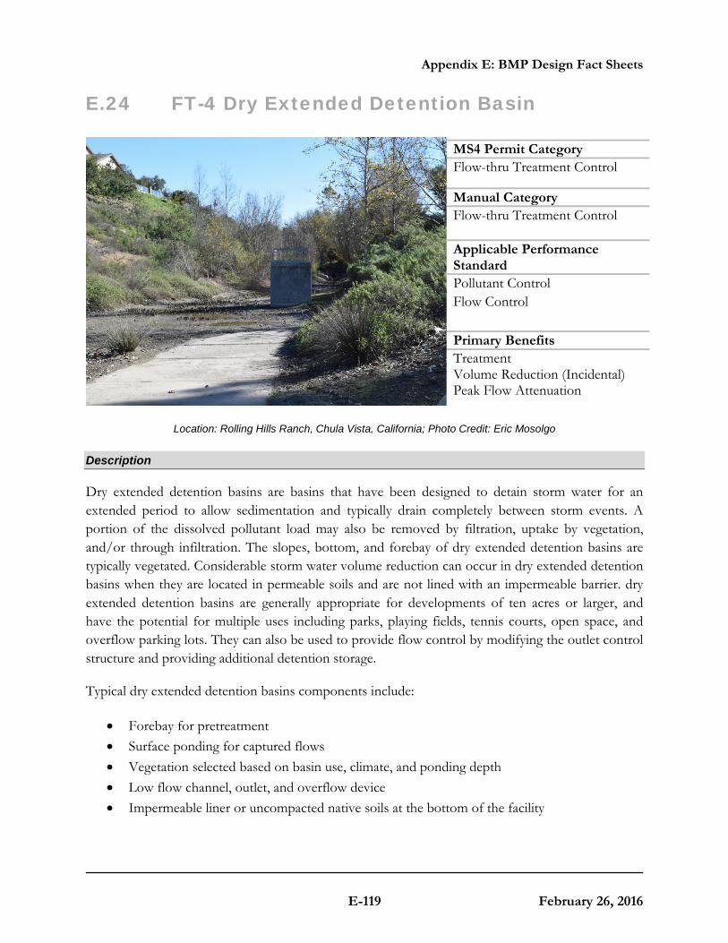
Appendix E: BMP Design Fact Sheets
E-119 February 26, 2016
E.24 FT-4 Dry Extended Detention Basin
Location: Rolling Hills Ranch, Chula Vista, California; Photo Credit: Eric Mosolgo
Description
Dry extended detention basins are basins that have been designed to detain storm water for an extended period to allow sedimentation and typically drain completely between storm events. A portion of the dissolved pollutant load may also be removed by filtration, uptake by vegetation, and/or through infiltration. The slopes, bottom, and forebay of dry extended detention basins are typically vegetated. Considerable storm water volume reduction can occur in dry extended detention basins when they are located in permeable soils and are not lined with an impermeable barrier. dry extended detention basins are generally appropriate for developments of ten acres or larger, and have the potential for multiple uses including parks, playing fields, tennis courts, open space, and overflow parking lots. They can also be used to provide flow control by modifying the outlet control structure and providing additional detention storage.
Typical dry extended detention basins components include:
• Forebay for pretreatment • Surface ponding for captured flows • Vegetation selected based on basin use, climate, and ponding depth • Low flow channel, outlet, and overflow device • Impermeable liner or uncompacted native soils at the bottom of the facility
MS4 Permit Category Flow-thru Treatment Control
Manual Category Flow-thru Treatment Control Applicable Performance Standard Pollutant Control Flow Control Primary Benefits Treatment Volume Reduction (Incidental) Peak Flow Attenuation

Appendix E: BMP Design Fact Sheets
E-120 February 26, 2016
Typical plan and Section view of a Dry Extended Detention Basin BMP

Appendix E: BMP Design Fact Sheets
E-121 February 26, 2016
Design Adaptations for Project Goals
Flow-thru treatment BMP for storm water pollutant control. The system is lined or un-lined to provide incidental infiltration and designed to detain storm water to allow particulates and associated pollutants to settle out. This configuration is considered to provide flow-thru treatment, not biofiltration treatment. Storage provided as surface ponding above a restricted outlet invert is considered detention storage and is included in calculations for the flow-thru treatment volume.
Integrated storm water flow control and pollutant control configuration. Dry extended detention basins can also be designed for flow control. The surface ponding can be designed to accommodate higher volumes than the storm water pollutant control volume and can utilize multi-stage outlets to mitigate both the duration and rate of flows within a prescribed range.
Design Criteria and Considerations
Dry extended detention basins must meet the following design criteria. Deviations from the below criteria may be approved at the discretion of County staff if it is determined to be appropriate:
Siting and Design Intent/Rationale
□ Placement observes geotechnical recommendations regarding potential hazards (e.g., slope stability, landslides, and liquefaction zones) and setbacks (e.g., slopes, foundations, utilities).
Must not negatively impact existing site geotechnical concerns.
□ An impermeable liner or other hydraulic restriction layer is included if site constraints indicate that infiltration or lateral flows should not be allowed.
Lining prevents storm water from impacting groundwater and/or sensitive environmental or geotechnical features. Incidental infiltration, when allowable, can aid in pollutant removal and groundwater recharge.
□ Contributing tributary area is large (typically ≥ 10 acres).
Dry extended detention basins require significant space and are more cost-effective for treating larger drainage areas.
□ Longitudinal basin bottom slope is 0 - 2%. Flatter slopes promote ponding and settling of particles.
□ Basin length to width ratio is
≥ 2:1 (L:W). A larger length to width ratio provides a longer flow path to promote settling.
□ Forebay is included that encompasses 20 - 30% of the basin volume.
A forebay to trap sediment can decrease frequency of required maintenance.
□ Side slopes are ≥ 3H:1V. Gentler side slopes are safer, less prone to erosion, able to establish vegetation more

Appendix E: BMP Design Fact Sheets
E-122 February 26, 2016
Siting and Design Intent/Rationale
quickly and easier to maintain.
□ Surface ponding drawdown time is between 24 and 96 hours.
Minimum drawdown time of 24 hours allows for adequate settling time and maximizes pollutant removal. Maximum drawdown time of 96 hours provides vector control.
□ Minimum freeboard provided is ≥1 foot for offline facilities and ≥2 feet for online facilities.
Freeboard provides room for head over overflow structures and minimizes risk of uncontrolled surface discharge.
□ Inflow and outflow structures are accessible by required equipment (e.g., vactor truck) for inspection and maintenance.
Maintenance will prevent clogging and ensure proper operation of the flow control structures.
□ A low flow channel or trench with a ≥ 2% slope is provided. A gravel infiltration trench is provided where infiltration is allowable.
Aids in draining or infiltrating dry weather flows.
□ Overflow is safely conveyed to a downstream storm drain system or discharge point. Size overflow structure to pass 100-year peak flow.
Planning for overflow lessens the risk of property damage due to flooding.
□ The maximum rate at which runoff is discharged is set below the erosive threshold for the site.
Extended low flows can have erosive effects.
Conceptual Design and Sizing Approach for Storm Water Pollutant Control Only
To design dry extended detention basins for storm water pollutant control only (no flow control required), the following steps should be taken:
1. Verify that siting and criteria have been met, including placement requirements, contributing tributary area, forebay volume, and maximum slopes for basin sides and bottom.
2. Calculate the DCV per Appendix B based on expected site design runoff for tributary areas. 3. Use the sizing worksheet to determine flow-thru treatment sizing of the surface ponding of
the dry extended detention basin, which includes calculations for a maximum 96-hour drawdown time.
Conceptual Design and Sizing Approach when Storm Water Flow Control is Applicable
Control of flow rates and/or durations will typically require significant surface ponding volume, and therefore the following steps should be taken prior to determination of storm water pollutant control design. Pre-development and allowable post-project flow rates and durations should be determined as discussed in Chapter 6 of the manual.
Appendix E: BMP Design Fact Sheets
E-123 February 26, 2016
1. Verify that siting and criteria have been met, including placement requirements, tributary area, and maximum slopes for basin sides and bottom.
2. Iteratively determine the surface ponding required to provide detention storage to reduce flow rates and durations to allowable limits. Flow rates and durations can be controlled from detention storage by altering outlet structure orifice size(s) and/or water control levels. Multi-level orifices can be used within an outlet structure to control the full range of flows.
3. If a dry extended detention basin cannot fully provide the flow rate and duration control required by this manual, an upstream or downstream structure with appropriate storage volume such as an additional basin or underground vault can be used to provide remaining controls.
4. After the dry extended detention basin has been designed to meet flow control requirements, calculations must be completed to verify if storm water pollutant control requirements to treat the DCV have been met.

Appendix E: BMP Design Fact Sheets
E-124 February 26, 2016
E.25 FT-5 Proprietary Flow-Thru Treatment Control BMPs The purpose of this fact sheet is to help explain the potential role of proprietary BMPs in meeting flow thru treatment control BMP requirements. The fact sheet does not describe design criteria like the other fact sheets in this appendix because this information varies by BMP product model.
Criteria for Use of a Proprietary BMP as a Flow-Thru Treatment Control BMP
A proprietary BMP may be acceptable as a “flow-thru treatment control BMP” under the following conditions:
(1) The BMP is selected and sized consistent with the method and criteria described in Appendix B.6;
(2) The BMP is designed and maintained in a manner consistent with its performance certifications (See explanation in Appendix B.6); and
(3) The BMP is acceptable at the discretion of County staff. While the County has no obligation to accept the use of any proposed proprietary flow-thru BMP, applicants will be provided a written explanation describing the rationale for the rejection of any proposed devices.
Guidance for Sizing Proprietary BMPs
Proprietary flow-thru BMPs must meet the same sizing guidance as other flow-thru treatment control BMPs. Guidance for sizing flow-thru BMPs to comply with requirements of this manual is provided in Appendix B.6.

Appendix E: BMP Design Fact Sheets
E-125 February 26, 2016
E.26 PL Plant List for Bioretention Facilities
Plant Name Irrigation Requirements Preferred Location in Basin Applicable Bioretention Sections (Un-Lined Facilities) Applicability to Flow-Through Planter?
(Lined Facility)
Latin Name Common Name
Temporary Irrigation during
Plant Establishment
Period
Permanent Irrigation (Drip
/ Spray)(1) Basin Bottom Basin Side
Slopes
Section A Treatment-Only Bioretention in
Hydrologic Soil Group A or B Soils
Section B Treatment-Only Bioretention in Hydrologic Soil
Group C or D soils
Section C Treatment Plus Flow
Control Bioretention in Hydrologic Soil
Group A or B Soils
Section D Treatment Plus
Flow Control Bioretention in Hydrologic Soil
Group C or D Soils
NO Applicable to Un-
lined Facilities Only
(Bioretention Only)
YES Can Use in Lined or
Un-Lined Facility (Flow-Through
Planter OR Bioretention)
TREES(2) Alnus rhombifolia White Alder X X X X X X X X
Platanus racemosa California Sycamore X X X X X X X X Salix lasiolepsis Arroyo Willow X X X X X X X
Salix lucida Lance-Leaf Willow X X X X X X X Sambucus mexicana Blue Elderberry X X X X X X X
SHRUBS / GROUNDCOVER
Achillea millefolium Yarrow X X X X X Agrostis palens Thingrass X X X X X X X
Anemopsis californica Yerba Manza X X X X X X X Baccharis douglasii Marsh Baccahris X X X X X X X X Carex praegracillis California Field Sedge X X X X X X X X
Carex spissa San Diego Sedge X X X X X X X X Carex subfusca Rusty Sedge X X X X X X X X X
Distichlis spicata Salt Grass X X X X X X X X Eleocharis
macrostachya Pale Spike Rush X X X X X X X X
Festuca rubra Red Fescue X X X X X X X Festuca californica California Fescue X X X X X X
Iva hayesiana Hayes Iva X X X X X Juncus Mexicana Mexican Rush X X X X X X X X X
Jucus patens California Gray Rush X X X X X X X X X Leymus condensatus
‘Canyon Prince’ Canyon Prince Wild Rye X X X X X X X X X
Mahonia nevinii Nevin’s Barberry X X X X X X X Muhlenburgia rigens Deergrass X X X X X X X X X Mimulus cardinalis Scarlet Monkeyflower X X X X X X
Ribes speciosum Fushia Flowering Goose. X X X X X Rosa californica California Wild Rose X X X X X X Scirpus cenuus Low Bullrush X X X X X X X X
Sisyrinchium bellum Blue-eyed Grass X X X X X
1. All plants will benefit from some supplemental irrigation during hot dry summer months, particularly those on basin side slopes and further inland. 2. All trees should be planted a min. of 10’ away from any drain pipes or structures.

Appendix E: BMP Design Fact Sheets
E-126 February 26, 2016
This page was left intentionally blank.