Embed Size (px)
Citation preview
BMI055, BMI085, BMI088, BMI090L, BMI160, BMI270 HSMI Document revision 1.3
Document release date February 2020
Document number BST-MIS-HS000-03
Sales Part Numbers
0 273 017 020, 0 273 141 365, 0 273 141 366, 0 273 141 134, 0 273 141 221, 0 273 141 187, 0 273 017 008
Notes Data and descriptions in this document are subject to change without notice. Product photos and pictures are for illustration purposes only and may differ from the real product appearance.
BMI055, BMI085, BMI088, BMI090L, BMI160, BMI270 Handling, Soldering And Mounting Instruction
Bosch Sensortec | BMI055, BMI085, BMI088, BMI090L, BMI160, BMI270 HSMI 2 | 16
Modifications reserved | Data subject to change without notice Document number: BST-MIS-HS000-03
Purpose of this document This document describes the recommended conditions and parameters to be applied when handling, soldering and mounting Bosch Sensortec’s Inertial Measurement Units (IMUs) to a PCB. This document applies to all mentioned Sales Part Numbers mentioned on the cover sheet. Important: In order to avoid any damages of the sensor and resultant loss of warranty please strictly keep with the instructions
described within this document
It is also strongly recommended to study the sensor data sheet prior to handling the sensor device
In case the Sales Part Number of your Bosch Sensortec device is not listed on the title page, please contact your Bosch Sensortec representative
In case you have any other questions, please do not hesitate to contact your Bosch Sensortec representative for further advice
Bosch Sensortec | BMI055, BMI085, BMI088, BMI090L, BMI160, BMI270 HSMI 3 | 16
Modifications reserved | Data subject to change without notice Document number: BST-MIS-HS000-03
Table of Contents
Purpose of this document ................................................................................................................................................. 2
1 Package outline ............................................................................................................................................................. 5
2 Landing pattern ............................................................................................................................................................. 5
3 Moisture sensitivity level (MSL) ................................................................................................................................... 5
4 RoHS compliancy / halogen content ........................................................................................................................... 5
5 Mounting recommendations ........................................................................................................................................ 5
5.1 Recommendations in detail ................................................................................................................................. 6
5.2 Recommendation details .................................................................................................................................... 7 Push-button contacts ............................................................................................................................. 7 Thermal hot-spots on the PCB ............................................................................................................... 7 Redundant PCB anchor points ............................................................................................................... 8 Mechanical stress maximum on the PCB ............................................................................................... 9 Distance to PCB anchor points ............................................................................................................... 9 Vibrating PCB ....................................................................................................................................... 10
5.3 Resin coatings .................................................................................................................................................. 10
6 Note on internal package structures ......................................................................................................................... 11
7 Device marking ............................................................................................................................................................ 11
8 Reflow soldering ......................................................................................................................................................... 11
8.1 Recommendation for soldering of sensors in LGA package .............................................................................. 11
8.2 Classification reflow profiles .............................................................................................................................. 12
8.3 Multiple reflow soldering cycles ........................................................................................................................ 12
9 Tape & reel ................................................................................................................................................................... 12
10 Further important mounting, assembly & handling recommendations ................................................................ 13
11 Legal disclaimer .......................................................................................................................................................... 14
12 Document history and modification .......................................................................................................................... 15
Bosch Sensortec | BMI055, BMI085, BMI088, BMI090L, BMI160, BMI270 HSMI 4 | 16
Modifications reserved | Data subject to change without notice Document number: BST-MIS-HS000-03
List of figures Figure 1: Push-button contacts ....................................................................................................................................... 7 Figure 2: Thermal hot-spots on the PCB ........................................................................................................................ 7 Figure 3: Redundant PCB anchor points ........................................................................................................................ 8 Figure 4: Mechanical stress maximum on the PCB ........................................................................................................ 9 Figure 5: Distance to PCB anchor points ........................................................................................................................ 9 Figure 6: Vibrating PCB ................................................................................................................................................ 10 Figure 7: Resin coatings ............................................................................................................................................... 10 Figure 8: Recommendation to keep the side of LGA free from solder material ............................................................. 11 Figure 9: Recommendation not to use underfill for LGA packages ............................................................................... 12
Bosch Sensortec | BMI055, BMI085, BMI088, BMI090L, BMI160, BMI270 HSMI 5 | 16
Modifications reserved | Data subject to change without notice Document number: BST-MIS-HS000-03
1 Package outline Please refer to the latest version of the corresponding product datasheet or preliminary datasheet.
2 Landing pattern Please refer to the latest version of the corresponding product datasheet or preliminary datasheet.
3 Moisture sensitivity level (MSL) The moisture sensitivity level of the device corresponds to JEDEC Level 1, see also IPC/JEDEC J-STD-020E "Joint Industry Standard: Moisture/Reflow Sensitivity Classification for non-hermetic Solid
State Surface Mount Devices" IPC/JEDEC J-STD-033D "Joint Industry Standard: Handling, Packing, Shipping and Use of Moisture/Reflow
Sensitive Surface Mount Devices" Both documents are available on JEDEC’s website. The sensor fulfils the lead-free soldering requirements of the above-mentioned IPC/JEDEC standard, i.e. reflow soldering with a peak temperature Tp up to 260°C.
4 RoHS compliancy / halogen content The sensors meet the requirements of the EC restriction of hazardous substances (RoHS) directive, see also:
RoHS–Directive 2011/65/EU and its amendments, including the amendment 2015/863/EU on the restriction of the use of certain hazardous substances in electrical and electronic equipment.
Bosch Sensortec BMI sensors are also halogen-free. For more details on the corresponding analysis results please contact your Bosch Sensortec representative. Corresponding chemical analysis certificates are available as separate documents from Bosch Sensortec.
5 Mounting recommendations MEMS sensors in general are high-precision measurement devices, which consist of electronic as well as mechanical silicon structures. Bosch Sensortec MEMS sensor devices are designed for precision, efficiency and mechanical robustness. However, in order to achieve best possible results for your design, the following recommendations should be taken into consideration when mounting the sensor on a printed circuit board (PCB). The scenarios described below –given as examples– may lead to a bending of the PCB, which as a consequence, might influence the performance of the sensor mounted on the PCB.
Bosch Sensortec | BMI055, BMI085, BMI088, BMI090L, BMI160, BMI270 HSMI 6 | 16
Modifications reserved | Data subject to change without notice Document number: BST-MIS-HS000-03
In order to evaluate and to optimize the considered placement position of the sensor on the PCB it is recommended to use additional tools during the design in phase, e.g.: regarding thermal aspects: infrared camera regarding mechanical stress: warpage measurements and/or FEM-simulations regarding shock robustness: drop tests of the device after soldering on the target application PCB
5.1 Recommendations in detail
It is generally recommended to keep a reasonable distance between the sensor mounting location on the PCB and the critical points described in the following examples. The exact value for a “reasonable distance” depends on many customer specific variables and must therefore be determined case by case.
It is generally recommended to minimize the PCB thickness (recommended: ≤ 0.8 mm), since a thin PCB shows less intrinsic stress, e.g. while being bent.
It is not recommended to place the sensor directly under or next to push-button contacts as this can result in mechanical stress.
It is not recommended to place the sensor in direct vicinity of extremely hot spots regarding temperature (e.g. a µController or a graphic chip) as this can result in heating-up the PCB and consequently also the sensor nearby.
It is not recommended to place the sensor in direct vicinity of a mechanical stress maximum (e.g. in the center of a diagonal crossover, refer to 5.2.4). Mechanical stress can lead to bending of the PCB and also of the sensor, nearby.
Do not mount the sensor too closely to a PCB anchor point, where the PCB is attached to a shelf (or similar) as this could also result in mechanical stress. To reduce potential mechanical stress, minimize redundant anchor points and/or loosen respective screws (refer to 5.2.3).
It is not recommended to mount the sensor in areas where resonant amplitudes (vibrations) of the PCB are likely or to be expected.
Please avoid partial coverage of the sensor by any kind of (epoxy) resin, as this can possibly result in mechanical stress.
Avoid mounting (and operation) of the sensor in the vicinity of strong electric and/or strong infrared radiation fields (IR).
When used together with a magnetometer, avoid mounting (and operation) of the sensor in the vicinity of strong magnetic fields
Avoid electrostatic charging of the sensor and of the device wherein the sensor is mounted.
Avoid mounting the sensor to flexible PCB substrates. In case you have any questions with regard to the mounting of the sensor on your PCB, or with regard to evaluate and/or to optimize the considered placement position of the sensor on your PCB, do not hesitate to contact us. If the above
Bosch Sensortec | BMI055, BMI085, BMI088, BMI090L, BMI160, BMI270 HSMI 7 | 16
Modifications reserved | Data subject to change without notice Document number: BST-MIS-HS000-03
mentioned recommendations cannot be realized appropriately, a specific in-line offset-calibration after placement of the device onto your PCB might help to minimize potentially remaining effects.
5.2 Recommendation details
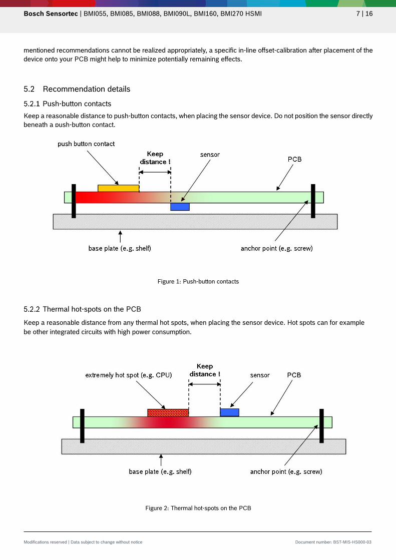
Push-button contacts Keep a reasonable distance to push-button contacts, when placing the sensor device. Do not position the sensor directly beneath a push-button contact.
Figure 1: Push-button contacts
Thermal hot-spots on the PCB
Keep a reasonable distance from any thermal hot spots, when placing the sensor device. Hot spots can for example be other integrated circuits with high power consumption.
Figure 2: Thermal hot-spots on the PCB
Bosch Sensortec | BMI055, BMI085, BMI088, BMI090L, BMI160, BMI270 HSMI 8 | 16
Modifications reserved | Data subject to change without notice Document number: BST-MIS-HS000-03
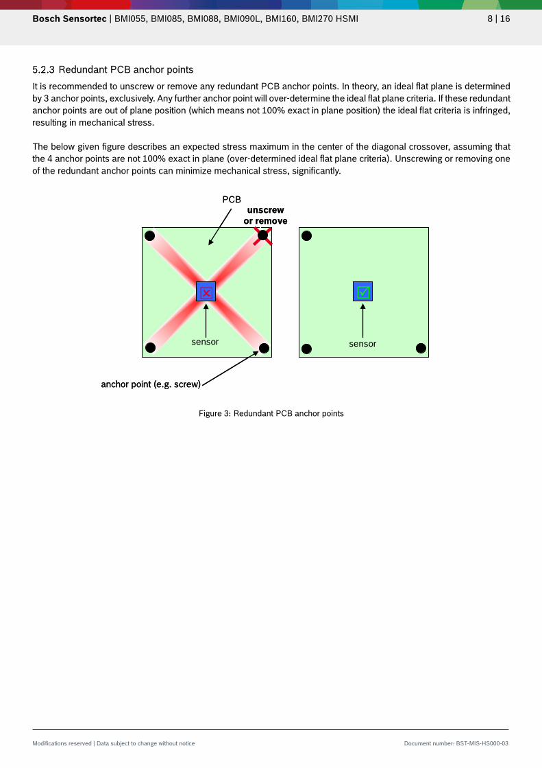
Redundant PCB anchor points It is recommended to unscrew or remove any redundant PCB anchor points. In theory, an ideal flat plane is determined by 3 anchor points, exclusively. Any further anchor point will over-determine the ideal flat plane criteria. If these redundant anchor points are out of plane position (which means not 100% exact in plane position) the ideal flat criteria is infringed, resulting in mechanical stress. The below given figure describes an expected stress maximum in the center of the diagonal crossover, assuming that the 4 anchor points are not 100% exact in plane (over-determined ideal flat plane criteria). Unscrewing or removing one of the redundant anchor points can minimize mechanical stress, significantly.
Figure 3: Redundant PCB anchor points
anchor point (e.g. screw)
PCB
sensor sensor
unscrewor remove
anchor point (e.g. screw)
PCB
sensor sensor
unscrewor remove
Bosch Sensortec | BMI055, BMI085, BMI088, BMI090L, BMI160, BMI270 HSMI 9 | 16
Modifications reserved | Data subject to change without notice Document number: BST-MIS-HS000-03
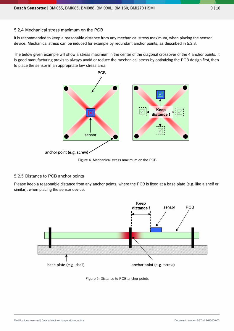
Mechanical stress maximum on the PCB
It is recommended to keep a reasonable distance from any mechanical stress maximum, when placing the sensor device. Mechanical stress can be induced for example by redundant anchor points, as described in 5.2.3. The below given example will show a stress maximum in the center of the diagonal crossover of the 4 anchor points. It is good manufacturing praxis to always avoid or reduce the mechanical stress by optimizing the PCB design first, then to place the sensor in an appropriate low stress area.
Figure 4: Mechanical stress maximum on the PCB
Distance to PCB anchor points
Please keep a reasonable distance from any anchor points, where the PCB is fixed at a base plate (e.g. like a shelf or similar), when placing the sensor device.
Figure 5: Distance to PCB anchor points
anchor point (e.g. screw)
PCB
Keepdistance !
sensor
anchor point (e.g. screw)
PCB
Keepdistance !
sensor
Bosch Sensortec | BMI055, BMI085, BMI088, BMI090L, BMI160, BMI270 HSMI 10 | 16
Modifications reserved | Data subject to change without notice Document number: BST-MIS-HS000-03
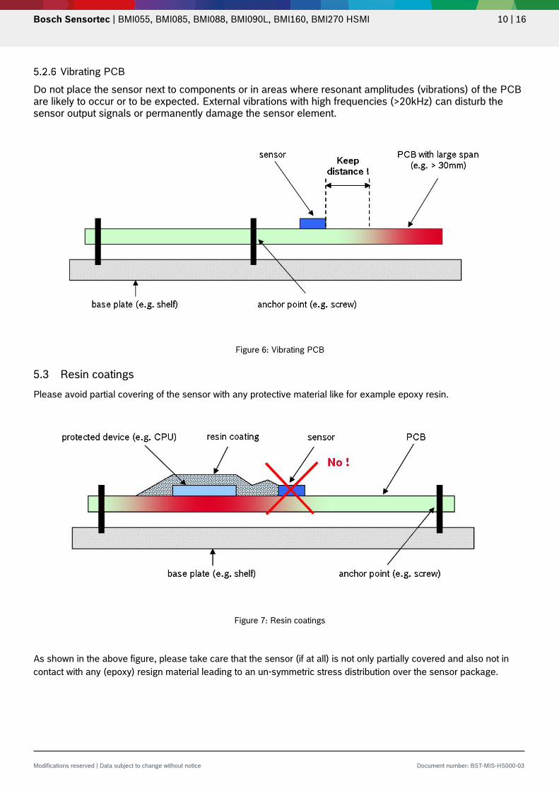
Vibrating PCB Do not place the sensor next to components or in areas where resonant amplitudes (vibrations) of the PCB are likely to occur or to be expected. External vibrations with high frequencies (>20kHz) can disturb the sensor output signals or permanently damage the sensor element.
Figure 6: Vibrating PCB
5.3 Resin coatings Please avoid partial covering of the sensor with any protective material like for example epoxy resin.
Figure 7: Resin coatings
As shown in the above figure, please take care that the sensor (if at all) is not only partially covered and also not in contact with any (epoxy) resign material leading to an un-symmetric stress distribution over the sensor package.
Bosch Sensortec | BMI055, BMI085, BMI088, BMI090L, BMI160, BMI270 HSMI 11 | 16
Modifications reserved | Data subject to change without notice Document number: BST-MIS-HS000-03
6 Note on internal package structures
Within the scope of Bosch Sensortec’s ambition to improve its products and secure the product supply while in mass production, Bosch Sensortec qualifies additional sources for the LGA package of its sensors. While Bosch Sensortec took care that all of the technical package parameters as described above are 100% identical for both sources, there can be differences in the chemical analysis and internal structural between the different package sources. However, as secured by the extensive product qualification processes at Bosch Sensortec, this has no impact on the usage or the quality of the sensor.
7 Device marking
Please refer to the latest version of the corresponding product data sheet or preliminary data sheet.
8 Reflow soldering
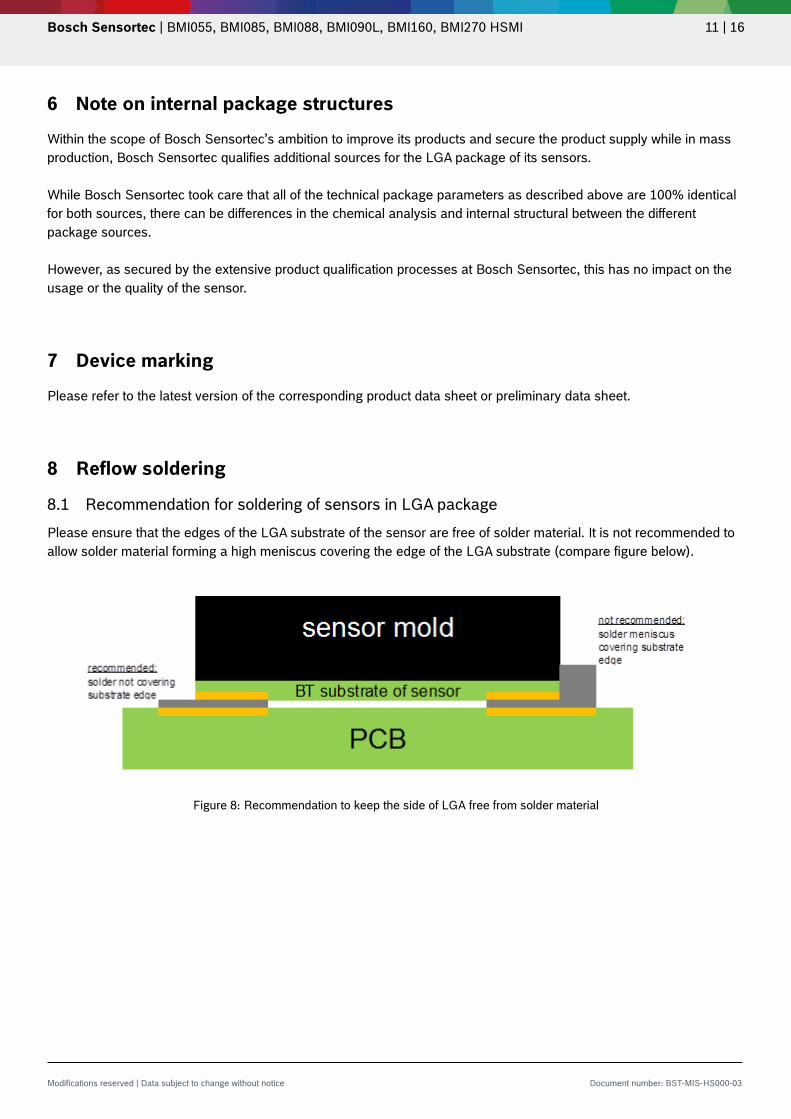
8.1 Recommendation for soldering of sensors in LGA package Please ensure that the edges of the LGA substrate of the sensor are free of solder material. It is not recommended to allow solder material forming a high meniscus covering the edge of the LGA substrate (compare figure below).
Figure 8: Recommendation to keep the side of LGA free from solder material

Bosch Sensortec | BMI055, BMI085, BMI088, BMI090L, BMI160, BMI270 HSMI 12 | 16
Modifications reserved | Data subject to change without notice Document number: BST-MIS-HS000-03
Using copper underfill for the LGA package is forbidden, compare figure below.
Figure 9: Recommendation not to use underfill for LGA packages
8.2 Classification reflow profiles The sensor fulfils the JEDEC and lead-free soldering requirements described in chapter 3, i.e. reflow soldering (after MSL1 pretreatment) with a peak temperature Tp up to 260°C.
8.3 Multiple reflow soldering cycles The product can withstand in total up to 3 reflow soldering cycles. This could be a situation where a PCB is mounted with devices from both sides (i.e. 2 reflow cycles necessary) and where in the next step an additional re-work cycle could be required (1 reflow).
9 Tape & reel Please refer to the latest version of the corresponding product datasheet or preliminary datasheet.
Bosch Sensortec | BMI055, BMI085, BMI088, BMI090L, BMI160, BMI270 HSMI 13 | 16
Modifications reserved | Data subject to change without notice Document number: BST-MIS-HS000-03
10 Further important mounting, assembly & handling recommendations Bosch Sensortec’s IMUs are designed to sense acceleration and rate of rotation with high accuracy even at low amplitudes and contain highly sensitive structures inside the sensor element. The MEMS sensor can tolerate mechanical shocks up to several thousand g's. However, these limits might be exceeded in conditions with extreme shock loads such as e.g. hammer blow on or next to the sensor, dropping of the sensor onto hard surfaces etc. We strongly recommend to avoid any g-forces beyond the limits specified in the data sheet during transport, handling and mounting of the sensors in a defined and qualified installation process. The IMUs have built-in protections against high electrostatic discharges or electric fields (2kV HBM); however, anti-static precautions should be taken as for any other CMOS component. Unless otherwise specified, proper operation can only occur when all terminal voltages are kept within the supply voltage range. Unused inputs must always be connected to a defined logic voltage level.
Bosch Sensortec | BMI055, BMI085, BMI088, BMI090L, BMI160, BMI270 HSMI 14 | 16
Modifications reserved | Data subject to change without notice Document number: BST-MIS-HS000-03
11 Legal disclaimer i. Engineering samples Engineering Samples are marked with an asterisk (*), (E) or (e). Samples may vary from the valid technical specifications of the product series contained in this data sheet. They are therefore not intended or fit for resale to third parties or for use in end products. Their sole purpose is internal client testing. The testing of an engineering sample may in no way replace the testing of a product series. Bosch Sensortec assumes no liability for the use of engineering samples. The Purchaser shall indemnify Bosch Sensortec from all claims arising from the use of engineering samples.
ii. Product use
Bosch Sensortec products are developed for the consumer goods industry. They may only be used within the parameters of this product data sheet. They are not fit for use in life-sustaining or safety-critical systems. Safety-critical systems are those for which a malfunction is expected to lead to bodily harm, death or severe property damage. In addition, they shall not be used directly or indirectly for military purposes (including but not limited to nuclear, chemical or biological proliferation of weapons or development of missile technology), nuclear power, deep sea or space applications (including but not limited to satellite technology). The resale and/or use of Bosch Sensortec products are at the purchaser’s own risk and his own responsibility. The examination of fitness for the intended use is the sole responsibility of the purchaser. The purchaser shall indemnify Bosch Sensortec from all third party claims arising from any product use not covered by the parameters of this product data sheet or not approved by Bosch Sensortec and reimburse Bosch Sensortec for all costs in connection with such claims. The purchaser accepts the responsibility to monitor the market for the purchased products, particularly with regard to product safety, and to inform Bosch Sensortec without delay of all safety-critical incidents. iii. Application examples and hints
With respect to any examples or hints given herein, any typical values stated herein and/or any information regarding the application of the device, Bosch Sensortec hereby disclaims any and all warranties and liabilities of any kind, including without limitation warranties of non-infringement of intellectual property rights or copyrights of any third party. The information given in this document shall in no event be regarded as a guarantee of conditions or characteristics. They are provided for illustrative purposes only and no evaluation regarding infringement of intellectual property rights or copyrights or regarding functionality, performance or error has been made.
Bosch Sensortec | BMI055, BMI085, BMI088, BMI090L, BMI160, BMI270 HSMI 15 | 16
Modifications reserved | Data subject to change without notice Document number: BST-MIS-HS000-03
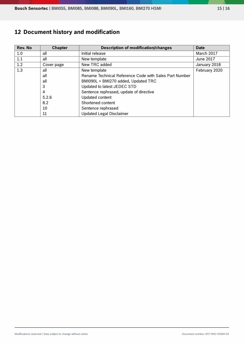
12 Document history and modification
Rev. No Chapter Description of modification/changes Date 1.0 all Initial release March 2017 1.1 all New template June 2017 1.2 Cover page New TRC added January 2018 1.3 all
all all 3 4 5.2.6 8.2 10 11
New template Rename Technical Reference Code with Sales Part Number BMI090L + BMI270 added, Updated TRC Updated to latest JEDEC STD Sentence rephrased, update of directive Updated content Shortened content Sentence rephrased Updated Legal Disclaimer
February 2020

Bosch Sensortec | BMI055, BMI085, BMI088, BMI090L, BMI160, BMI270 HSMI 16 | 16
Modifications reserved | Data subject to change without notice Document number: BST-MIS-HS000-03
Bosch Sensortec GmbH Gerhard-Kindler-Straße 9 72770 Reutlingen / Germany [email protected] www.bosch-sensortec.com Modifications reserved Preliminary - specifications subject to change without notice Document number: BST-MIS-HS000-03