Embed Size (px)
Citation preview
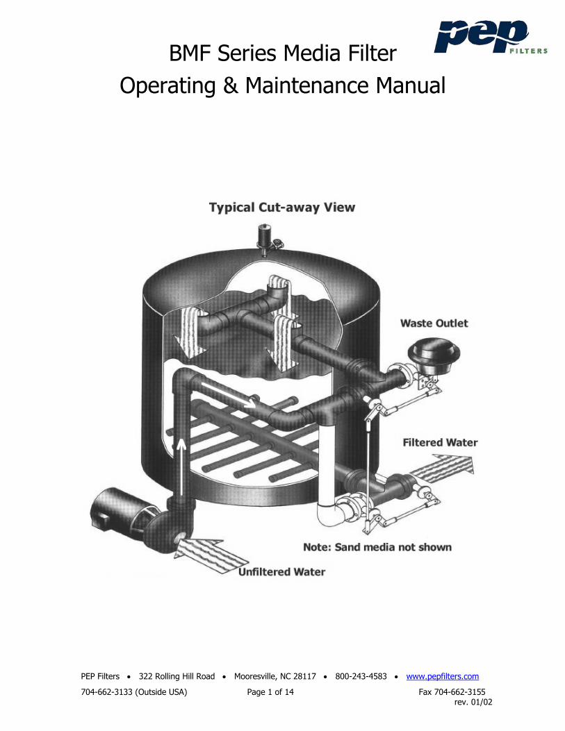
BMF Series Media Filter
Operating & Maintenance Manual
PEP Filters • 322 Rolling Hill Road • Mooresville, NC 28117 • 800-243-4583 • www.pepfilters.com
704-662-3133 (Outside USA) Page 1 of 14 Fax 704-662-3155 rev. 01/02
BMF Series Media Filter Operating & Maintenance Manual
PEP Filters • 322 Rolling Hill Road • Mooresville, NC 28117 • 800-243-4583 • www.pepfilters.com
704-662-3133 (Outside USA) Page 2 of 14 Fax 704-662-3155 rev. 01/02
Process Efficiency Products (“PEP Filters”) filtration equipment has been designed to give long, trouble-free service when properly installed, operated and maintained. This manual contains important installation procedures and should be read prior to installing. This manual is also a guide for proper filter operation, maintenance and winterizing. It is important that maintenance personnel review this manual carefully, including the Safety Precautions and Warnings located on page 7 before performing any maintenance on this industrial water filter.
Note that the recommendations on the frequency service are minimums, and where operating conditions are severe, the service should be performed more often. For each required service, follow the procedures outlined under the Maintenance Procedures section in this manual. If additional information beyond the scope of this manual is required, contact your local PEP Representative or PEP Filters.
Table of Contents Page Page Typical BMF Filter; Cut-away 1 Filter Vessel 6 Overview & General Info. 2 Water Treatment 7 Filter Operation 3 Factory Authorized Parts 7 Installation 3 Safety Precautions 7 Rigging 3 Warranty 7 Piping 3, 4 Maintenance Schedule-Table 1 8 Media Loading 4 Connection Sizes-Table 2 9 Operation and Maintenance 4 BMF Flow Rates-Table 3 9 Initial & Seasonal Start-up 4, 5 Electrical Requirements-Table 4 9 Start-up - after first hour 5 Electrical Requirements-Table 4A 10 Normal Operation 5 Media Quantities-Table 5 10 Cold Weather Operation 5 Media Quantities-Table 5A 11 Maintenance Procedures 6 Filter System Drawing 12 Backwashing 6 Filter Parts 12~14
BMF Series Media Filter Operating & Maintenance Manual
PEP Filters • 322 Rolling Hill Road • Mooresville, NC 28117 • 800-243-4583 • www.pepfilters.com
704-662-3133 (Outside USA) Page 3 of 14 Fax 704-662-3155 rev. 01/02
General Description
The BMF Series Industrial Water Filters are permanent media type units specifically designed to clean cooling tower and other industrial process water. The filters may be used for both side-stream and full stream applications in pressurized and non-pressurized systems. Standard BMF series filter vessels are rated for 50 psig (345 kpa). Optional higher pressure ratings of 100 psig (689 kpa) and 150 psig (1034 kpa) are also available. Vessels are available in both non-code and ASME code construction. Filter Operation
Water from the system is pumped through the over-drain assembly at the top of the filter tank and distributed evenly over the media. Unfiltered water flows downward through the filter media where suspended particles are trapped. The filtered water then passes through the vessel and out the under-drain assembly at the bottom of the filter and returns to the system.
When the trapped particles cause the pressure differential across the media bed to reach a pre-determined pressure of approximately 16 psig, the valves are automatically or manually repositioned, and the media is washed. The media is backwashed with a rigorous scouring action, releasing trapped particles within the media. The dirty water passes from the filter vessel through the over-drain assembly at the top of the vessel and flows to drain. After the backwash cycle (field adjustable and factor pre-set at 3 minutes), the filter valves are again repositioned and the filtration cycle is resumed. Installation
Unpacking
When the PEP Industrial Water Filter is delivered to the jobsite, it should be inspected thoroughly to ensure that all required items have been received and that filter equipment is free of any damage that may have occurred in transit. Any damage must be noted on the bill of lading at the time of receipt. Otherwise, there is no recourse to recover the cost of damaged goods.
The filter model number appears on a nameplate located on the unit and should be checked against the invoice/packing list. Rigging
BMF filters should be lifted with a forklift or overhead crane. If these units are lifted with an overhead crane, lifting straps must be located below the filter skid and should not come in contact with the filter components. If no skid supplied, lift from the lifting lugs located on the filter vessel top.
All PEP industrial water filters should be rigidly anchored to the floor or support steel by means of anchor bolts. All BMF filters have an anchoring provision.
Once the filter is installed in its permanent location, the pressure gauge and air relief valves should be installed on the top of the filter tank (some units will have these items already installed). The sand media is loaded into the filter next. Refer to the section in this manual “Loading the Media” for the proper loading procedure and the appropriate quantity of media necessary for each size filter vessel. Piping
The BMF filter should be installed using the pipe size indicated in Table 2.
Connect the unfiltered source water from the system sump or piping to the connection labeled “Inlet”. Note: If the filter is supplied with a pump and the inlet connection is located above the operating water level of the system sump, install a foot/check valve to maintain a prime on the pump and prevent loss of pump suction.
Connect the return line from the connection labeled "Outlet" to the system sump or filtered water return piping.
A service or isolation valve should be installed on the inlet, outlet and city water line (if city water is used) to allow filter servicing. For units using a backwash source other than the system sump, refer to Table 3 for the required backwash flow rate. Attach this line to the connection labeled "City Water". The maximum city water backwash supply pressure on the BMF filter vessel should never exceed the vessel pressure rating. If public or municipal water is used for backwash, a back/low prevention device or check valve is required on the line city water line (in accordance with local or other governing codes).
BMF Series Media Filter Operating & Maintenance Manual
PEP Filters • 322 Rolling Hill Road • Mooresville, NC 28117 • 800-243-4583 • www.pepfilters.com
704-662-3133 (Outside USA) Page 4 of 14 Fax 704-662-3155 rev. 01/02
Connect a backwash waste line to the connection labeled "Waste". This line carries the backwash wastewater to drain. Do not install a valve in the waste line. Refer to Table 3 for the minimum and maximum backwash flow rates. Note: If the drain is not large enough to handle the volume of water during backwash, it may be necessary to use a backwash water holding tank to buffer the backwash flow rate from the filter to the waste drain. A valve can be used to regulate the flow from the holding tank at a reduced flow rate that is suitable for the drain. Do not reduce the waste line pipe to regulate backwash flow rate as this will adversely affect the backwash cycle and cause accumulated waste in the filter vessel.
All inter-connecting piping, fittings, valves, or other accessories connected to the filter system (whether supplied by PEP or others) must be independently supported to eliminate stress on piping. Check with local or other governmental authority to ensure compliance with applicable codes.
All BMF filter vessels have a drain plug located on the bottom. Loading the Filter Media
The special sand media used in BMF industrial water filters is shipped in one cubic foot bags and each bag weighs 100 lbs. Media quantity may vary with vessel pressure ratings. Correct quantities will be noted on the shipping and inspection records for each filter system.
! Important ! To avoid damage to the filter under-drain, the filter vessel must be filled with water (1/3 ~ 1/2 full) before loading media into the vessel. The under-drain support gravel (Unigran 475) is loaded first. For single media applications, the silica sand is loaded next. Check filter internals for damage before loading the media. Operation and Maintenance
Initial and Seasonal Start-up
Before initial start-up or after a down period, the filter should be thoroughly inspected and cleaned.
! Caution, safety first ! The first five steps in the following procedure must be performed with the electric power off, locked and tagged at the main panel. Maintenance personnel should follow the recommended safety precautions found in the Safety Precautions section in this manual prior to initial and seasonal start-up.
1. On BMF filters with pumps and pre-strainers, loosen the bolts around the pump pre-strainer tank lid. Remove the lid, inspect the O-ring seal and lubricate. Remove debris from the pump pre-strainer basket. Replace the basket, lid and bolts. Now is a good time to prime the pump suction line.
2. Turn the pump and motor shaft by hand to ensure free rotation.
3. On BMF filters with manual backwash only, rotate the valves manually by moving the valve linkage up and down to ensure free operation. Make sure the valves and linkage are in the backwash position before start-up. This initial backwash will help to remove any dust particulate in the media before the filtration cycle begins.
4. Loosen the access port and hand hole covers and lubricate the bolts if necessary.
5. Inspect the over-drain assembly and media. If the media is contaminated, remove the foreign material or replace the media. Replace the access port and hand hole covers.
6. Open the air relief valve on top of the filter tank. Start the pump motor briefly and check the arrow on the pump volute for proper rotation. Turn the pump motor off. Do not operate the pump for an extended period of time with the pump rotating backwards. If rotation is backward, have a qualified electrician change pump motor leads to correct rotation.
7. With the air relief valve open, check the shut-off valves in the filter inlet and outlet water lines to verify they are open. Make sure the pump is primed. Start the pump and allow the filter vessel to fill. Close the manual air relief valve on top of the vessel after all air has been vented from the vessel.
8. Check the voltage and current of all leads on the pump motor. The current draw should not exceed the pump
BMF Series Media Filter Operating & Maintenance Manual
PEP Filters • 322 Rolling Hill Road • Mooresville, NC 28117 • 800-243-4583 • www.pepfilters.com
704-662-3133 (Outside USA) Page 5 of 14 Fax 704-662-3155 rev. 01/02
motor nameplate rating.
9. Check the unit for any unusual noise or vibration.
10. Check the unit for any air or water leaks. Any air leaks in the pump suction piping must be found and repaired. Failure to do so could result in poor performance and/or personal injury.
11. Backwash the filter. After backwashing the filter, check the pressure gauge on top of the filter tank and record the clean media operating pressure gauge (inlet gauge). The media should be backwashed whenever the pressure drop across the filter media reaches 16 psig, or every 24 hours, whichever occurs first.
After First Hour of Operation
1. With the filter pump running, open the air relief valve on top of the filter vessel. Close the valve after the air has been purged from the system. Excessive air release generally indicates a leak, which must be repaired. Air accumulation in the filter vessel can result in an unsafe condition due to the stored high energy potential of any compressed air within the vessel.
2. Again, check the unit for any unusual noise or vibration.
3. Again, check unit for any air or water leaks. Operation During operation, to ensure long term dependable operation, the filter should be inspected, cleaned and lubricated on a regular basis. The required service functions and recommended frequency (minimums) for each are shown in the Operating and Maintenance Table. Cold Weather Operation
For PEP industrial water filters that will be exposed to below freezing ambient temperatures require protection to prevent freezing. Installation in a heated indoor space is the best means of preventing water from freezing in a filter. Where indoor installation is impractical because of filter location or space limitations, supplemental heat must be supplied through the use of electrical heater tape and insulation. The parts of the filter that must be heat traced and insulated are: pump, pump pre-strainer, pump piping and valves, differential pressure switch tubing and filter vessel. The unit should be drained when it is to be shut down for any period of time. Refer to the following (Seasonal Shutdown) section in this the manual for recommendations. Seasonal Shutdown
The following services should be performed when the unit is to taken out of service for a extended time period.
1. Shut off all electrical power. 2. Close the shut-off valves in the filter inlet and outlet water lines. For units using a backwash source other than the
system, close the shut off valve in the line from that source also. 3. Drain all external piping to and from the filter. 4. Open the manual vent valves and open the drain line to the filter tank and piping. After the water has drained,
close the drain and vent. 5. On manual units only, rotate the valves manually by moving the linkage up and down to ensure operation without
obstruction. 6. Loosen the bolts that hold the filter vessel access covers in place and remove the cover. Lubricate the bolts if
necessary. Replace the cover gaskets if necessary. 7. Inspect the over-drain assembly and media pack. If the media is contaminated, remove the foreign material and
replace the filter media if necessary. Replace the filter vessel access covers and secure the bolts.
BMF Series Media Filter Operating & Maintenance Manual
PEP Filters • 322 Rolling Hill Road • Mooresville, NC 28117 • 800-243-4583 • www.pepfilters.com
704-662-3133 (Outside USA) Page 6 of 14 Fax 704-662-3155 rev. 01/02
Maintenance Procedures
Pump Pre-strainer (if equipped)
Warning: Disconnect all electrical power prior to performing pump maintenance. The filter pre-strainer basket on the pump inlet must be checked regularly and kept free of debris. Failure to do so may damage the pump and/or motor. Shut off the power, close the valves, open the manual air relief valve, remove bolts and the pre-strainer cover. Lift the basket out of the housing and remove any foreign material. Replace the basket, lubricate the O-ring, install the cover and tighten the bolts. Backwashing
Differential pressure across the filter media progressively increases as trapped particulate accumulate in the filter media bed. On filters equipped with automatic backwash, the backwash cycle is initiated upon reaching a 16 psig pressure differential. Since units with automatic controls perform this function as necessary, a detailed backwash procedure is only provided for manual units. However, automatic units can be manually backwashed by pressing the manual push-button switch located on the control panel. The backwash cycle is field adjustable on most units and is factory set at three minutes. To prevent unfiltered water from “short circuiting” through the media and to extend media life, the filter should be backwashed regularly; at least once every couple of days on manual units.
For manual backwash filters using backwash water source other than the unfiltered source water (e.g. city water):
1. Shut off the electrical power to the pump motor. 2. Move the handle on the linkage to position the valves in backwash mode. 3. Allow the filter to backwash for approximately three minutes. 4. Move the handle on the linkage to return the valves to the filtration mode. 5. Re-start the pump motor.
For manual control units using the system water for backwash:
1. Shut off the electrical power to the pump motor. 2. Move the handle on the linkage to position the valves in the backwash mode. 3. Re-start the pump motor. 4. Allow the filter to backwash for approximately three minutes. 5. Shut off the electrical power to the pump motor. 6. Move the handle on the linkage to return the valves to the filtration mode. 7. Re-start the pump motor.
Filter Vessel
The filter vessel internal components should be visually inspected annually or whenever backwashing does not reduce the pressure of the filter tank to the starting media gauge pressure. Remove the access port on the top of the tank to inspect the internal components.
Note: Always use care and follow proper shut-down procedures. Inspect the over-drain assembly for any debris blockage or damage and clean or replace if necessary. Remove and inspect the media. The BMF filters have hand access ports located on the side of the tank for easy removal of the media and inspection of the under-drain assembly. Over a period of time, foreign matter may become imbedded in the media pack that cannot be removed by backwashing. Contaminated media should be disposed in accordance with state and federal requirements. Unscrew the under-drain laterals and inspect for blockage or damage. Clean or replace if necessary. If replacement of one or more laterals is necessary, it is recommended to replace all laterals in the under-drain. Refill the vessel with the proper amount of new media, following the procedure for media loading.
BMF Series Media Filter Operating & Maintenance Manual
PEP Filters • 322 Rolling Hill Road • Mooresville, NC 28117 • 800-243-4583 • www.pepfilters.com
704-662-3133 (Outside USA) Page 7 of 14 Fax 704-662-3155 rev. 01/02
Water Treatment
Filtration is an effective way of reducing and managing the level of contamination in a fluid system. Still, there are other components of equal importance in a water treatment program. For cooling tower water and closed loop systems, often the water must be further treated to inhibit or prevent the deposition of dissolved solids on heat transfer surfaces. As water evaporates, without proper treatment, the concentration of dissolved solids increases and will result in scale build-up on heat transfer surfaces. Additionally, water often requires treatment for the control of corrosion, bacteria (including Legionella) and other biological contaminants.
To control all potential contaminants, a comprehensive water treatment program must be developed and employed. In some cases, a simple bleed-off in the system may be adequate for scale control. The filter backwash constitutes a portion of the bleed. For specific recommendations on water treatment, a water treatment professional should be consulted. Factory Authorized Parts
Factory authorized parts are available through your local PEP Filters representative. Contact the factory if assistance is required. Be sure to include the filter serial number and model when ordering parts.
To facilitate servicing the unit, it is suggested that the following spare parts be carried on hand: 1. O-ring or gasket for filter tank access port and hand hole 2. O-ring seal or gasket for pump pre-strainer lid (if applicable). 3. Seal kit for pump (if applicable). 4. Transformer fuse (automatic units only).
Safety Precautions
All electrical, mechanical and rotating machinery constitute a potential hazard; particularly for those not familiar with the design, construction, and operation. Accordingly, adequate safeguards (including use of protective enclosures when necessary) should be taken with this equipment both to safeguard the public from injury and to prevent damage to the filtration equipment and the premises.
Filter system operation, maintenance and repair should be undertaken only by trained and qualified personnel. All such personnel should be thoroughly familiar with the equipment, the associated system and controls, and the procedures set forth in this manual. Proper care, procedures, and tools must be used in handling, lifting, installing, operating, maintaining, and repairing this equipment, to prevent personal injury and/or property damage.
For the protection of authorized service and maintenance personnel, the pump motor associated with this equipment should be installed with a lockable disconnect switch located in close proximity and within sight of the filtration system. No service work should be performed on or near the pump motors without first ensuring that the pump motor has been electrically disconnected and locked out.
The re-circulating water system may contain chemicals or biological contaminants that could be harmful if inhaled or ingested. Accordingly, personnel that may be exposed directly to the mist produced by water jets or compressed air (if these are used to clean portions or components of the filter) should wear respirators with HEPA filters, NIOSH/MSHA approved number TC-21C-142 / TC-21C-182. Warranty Policy
PEP warrants all products to be manufactured free from defects in material and workmanship for a period of 12 months after start-up or 18 months from the date of shipment, whichever occurs first. In the event of any such defect and at the factory’s option, PEP will either repair or provide a replacement free of charge. Replacement parts will be F.O.B. factory. In any event, PEP Filters will not be responsible for consequential damages.
This warranty does not apply to any defect that can be attributed to accident, alteration, abuse, misuse, negligence or acts of God.
BMF Series Media Filter Operating & Maintenance Manual
PEP Filters • 322 Rolling Hill Road • Mooresville, NC 28117 • 800-243-4583 • www.pepfilters.com
704-662-3133 (Outside USA) Page 8 of 14 Fax 704-662-3155 rev. 01/02
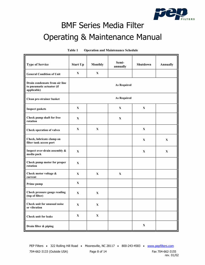
Table 1 Operation and Maintenance Schedule
Type of Service
Start Up
Monthly
Semi-
annually
Shutdown
Annually
General Condition of Unit X X
Drain condensate from air line to pneumatic actuator (if applicable)
As Required
Clean pre-strainer basket As Required
Inspect gaskets X X X
Check pump shaft for free rotation
X X
Check operation of valves X X X
Check, lubricate clamp on filter tank access port
X X
Inspect over-drain assembly & media pack
X X X
Check pump motor for proper rotation
X
Check motor voltage & current
X X X
Prime pump X
Check pressure gauge reading (top of filter)
X X
Check unit for unusual noise or vibration
X X
Check unit for leaks X X
Drain filter & piping X
BMF Series Media Filter Operating & Maintenance Manual
PEP Filters • 322 Rolling Hill Road • Mooresville, NC 28117 • 800-243-4583 • www.pepfilters.com
704-662-3133 (Outside USA) Page 9 of 14 Fax 704-662-3155 rev. 01/02
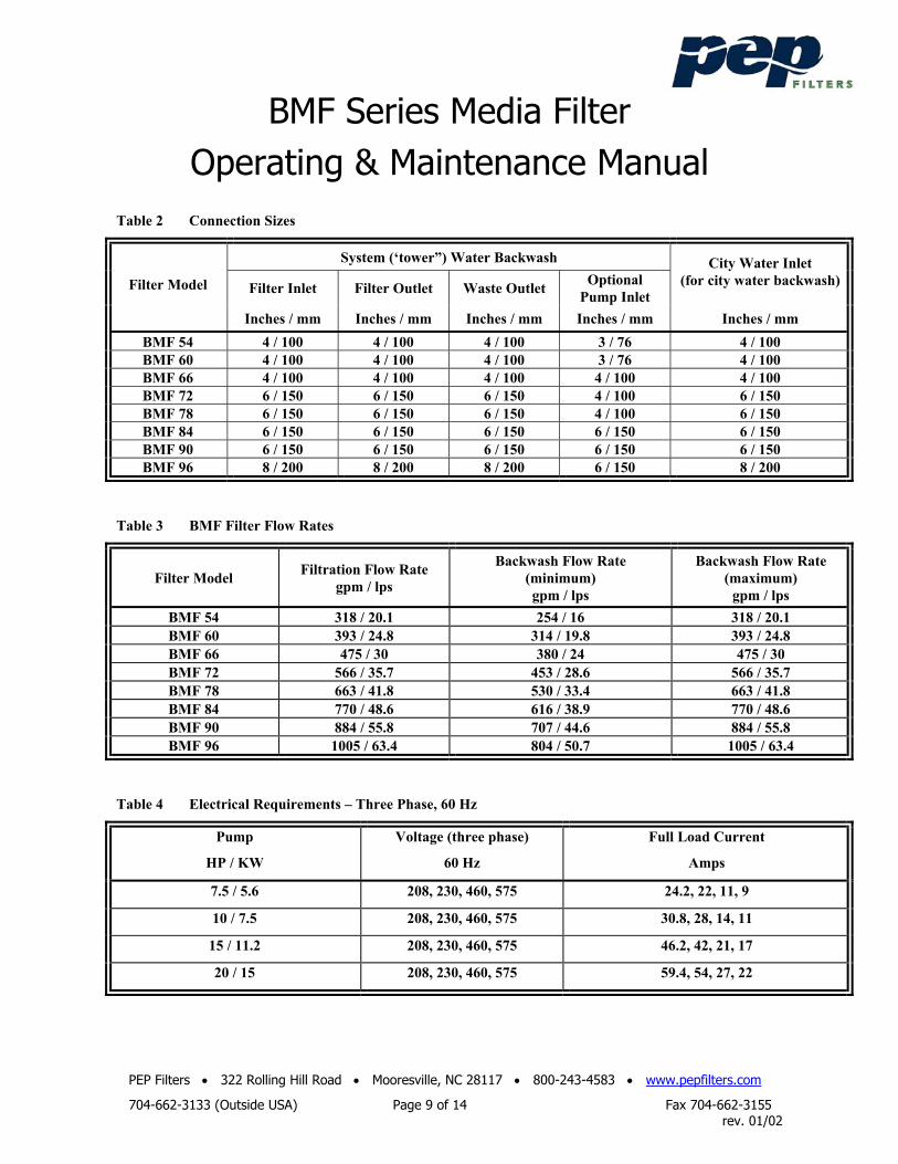
Table 2 Connection Sizes
System (‘tower”) Water Backwash
Filter Inlet Filter Outlet Waste Outlet Optional Pump Inlet
City Water Inlet (for city water backwash) Filter Model
Inches / mm Inches / mm Inches / mm Inches / mm Inches / mm BMF 54 4 / 100 4 / 100 4 / 100 3 / 76 4 / 100 BMF 60 4 / 100 4 / 100 4 / 100 3 / 76 4 / 100 BMF 66 4 / 100 4 / 100 4 / 100 4 / 100 4 / 100 BMF 72 6 / 150 6 / 150 6 / 150 4 / 100 6 / 150 BMF 78 6 / 150 6 / 150 6 / 150 4 / 100 6 / 150 BMF 84 6 / 150 6 / 150 6 / 150 6 / 150 6 / 150 BMF 90 6 / 150 6 / 150 6 / 150 6 / 150 6 / 150 BMF 96 8 / 200 8 / 200 8 / 200 6 / 150 8 / 200
Table 3 BMF Filter Flow Rates
Filter Model Filtration Flow Rate gpm / lps
Backwash Flow Rate (minimum) gpm / lps
Backwash Flow Rate (maximum)
gpm / lps BMF 54 318 / 20.1 254 / 16 318 / 20.1 BMF 60 393 / 24.8 314 / 19.8 393 / 24.8 BMF 66 475 / 30 380 / 24 475 / 30 BMF 72 566 / 35.7 453 / 28.6 566 / 35.7 BMF 78 663 / 41.8 530 / 33.4 663 / 41.8 BMF 84 770 / 48.6 616 / 38.9 770 / 48.6 BMF 90 884 / 55.8 707 / 44.6 884 / 55.8 BMF 96 1005 / 63.4 804 / 50.7 1005 / 63.4
Table 4 Electrical Requirements – Three Phase, 60 Hz
Pump
HP / KW
Voltage (three phase)
60 Hz
Full Load Current
Amps
7.5 / 5.6 208, 230, 460, 575 24.2, 22, 11, 9
10 / 7.5 208, 230, 460, 575 30.8, 28, 14, 11
15 / 11.2 208, 230, 460, 575 46.2, 42, 21, 17
20 / 15 208, 230, 460, 575 59.4, 54, 27, 22
BMF Series Media Filter Operating & Maintenance Manual
PEP Filters • 322 Rolling Hill Road • Mooresville, NC 28117 • 800-243-4583 • www.pepfilters.com
704-662-3133 (Outside USA) Page 10 of 14 Fax 704-662-3155 rev. 01/02
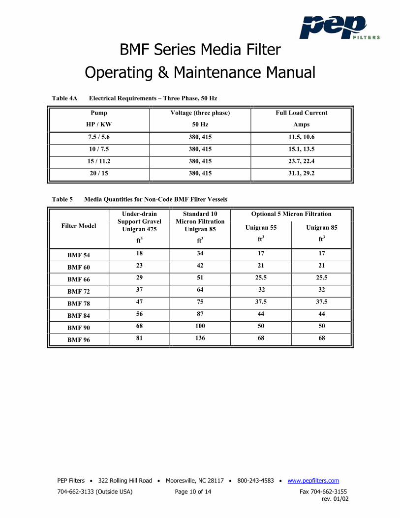
Table 4A Electrical Requirements – Three Phase, 50 Hz
Pump
HP / KW
Voltage (three phase)
50 Hz
Full Load Current
Amps
7.5 / 5.6 380, 415 11.5, 10.6
10 / 7.5 380, 415 15.1, 13.5
15 / 11.2 380, 415 23.7, 22.4
20 / 15 380, 415 31.1, 29.2
Table 5 Media Quantities for Non-Code BMF Filter Vessels
Optional 5 Micron Filtration
Filter Model
Under-drain Support Gravel
Unigran 475
ft3
Standard 10 Micron Filtration
Unigran 85
ft3
Unigran 55
ft3
Unigran 85
ft3
BMF 54 18 34 17 17
BMF 60 23 42 21 21
BMF 66 29 51 25.5 25.5
BMF 72 37 64 32 32
BMF 78 47 75 37.5 37.5
BMF 84 56 87 44 44
BMF 90 68 100 50 50
BMF 96 81 136 68 68
BMF Series Media Filter Operating & Maintenance Manual
PEP Filters • 322 Rolling Hill Road • Mooresville, NC 28117 • 800-243-4583 • www.pepfilters.com
704-662-3133 (Outside USA) Page 11 of 14 Fax 704-662-3155 rev. 01/02
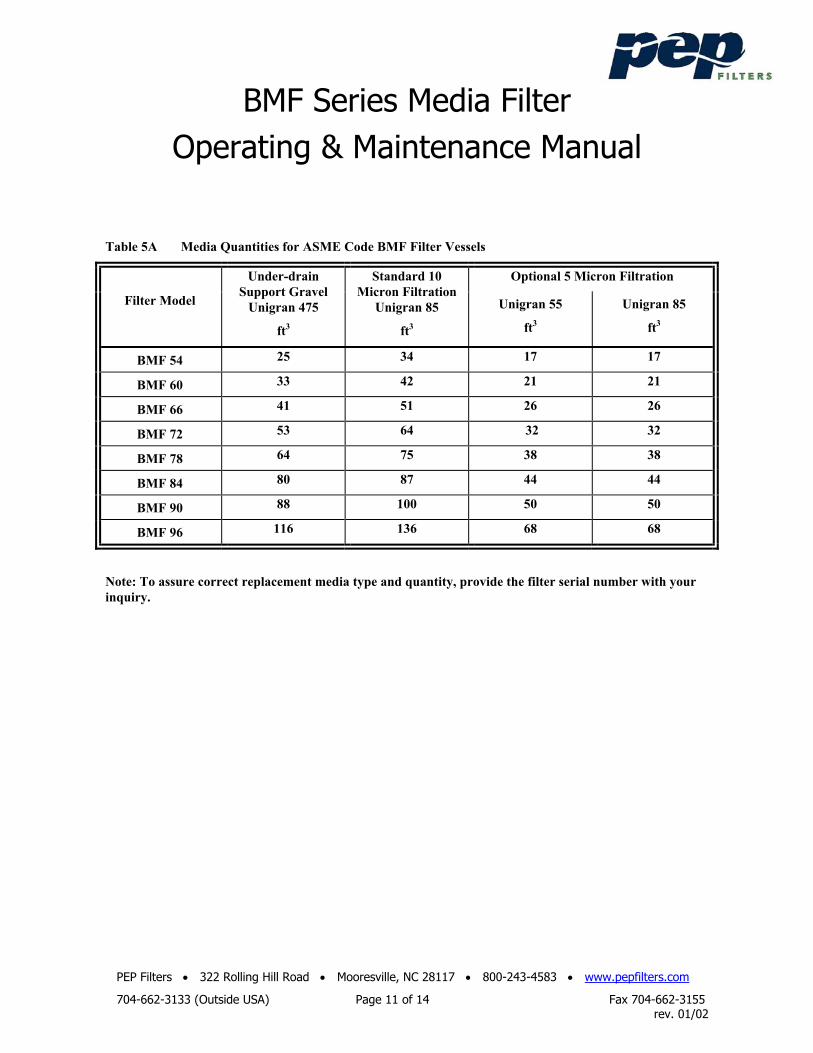
Table 5A Media Quantities for ASME Code BMF Filter Vessels
Optional 5 Micron Filtration
Filter Model
Under-drain Support Gravel
Unigran 475
ft3
Standard 10 Micron Filtration
Unigran 85
ft3
Unigran 55
ft3
Unigran 85
ft3
BMF 54 25 34 17 17
BMF 60 33 42 21 21
BMF 66 41 51 26 26
BMF 72 53 64 32 32
BMF 78 64 75 38 38
BMF 84 80 87 44 44
BMF 90 88 100 50 50
BMF 96 116 136 68 68
Note: To assure correct replacement media type and quantity, provide the filter serial number with your inquiry.
BMF Series Media Filter Operating & Maintenance Manual
PEP Filters • 322 Rolling Hill Road • Mooresville, NC 28117 • 800-243-4583 • www.pepfilters.com
704-662-3133 (Outside USA) Page 12 of 14 Fax 704-662-3155 rev. 01/02
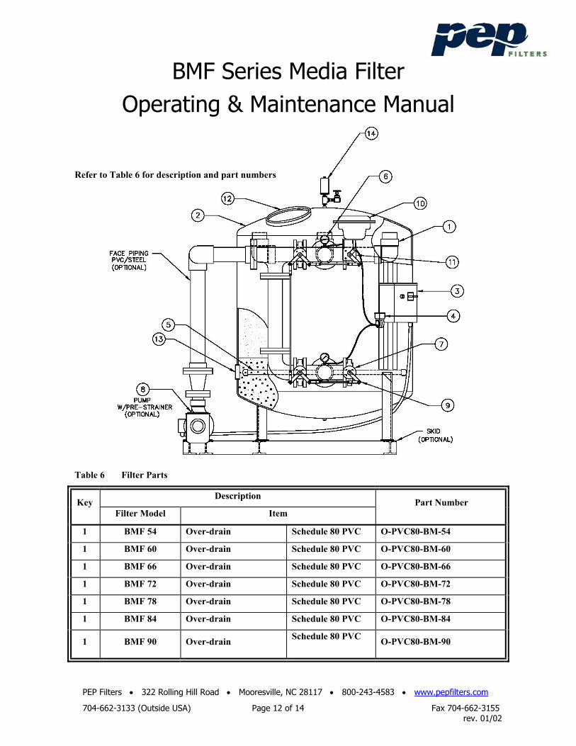
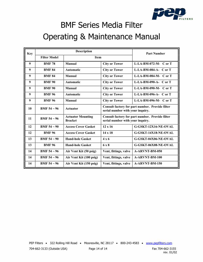
Refer to Table 6 for description and part numbers
Table 6 Filter Parts
Description Key
Filter Model Item Part Number
1 BMF 54 Over-drain Schedule 80 PVC O-PVC80-BM-54
1 BMF 60 Over-drain Schedule 80 PVC O-PVC80-BM-60
1 BMF 66 Over-drain Schedule 80 PVC O-PVC80-BM-66
1 BMF 72 Over-drain Schedule 80 PVC O-PVC80-BM-72
1 BMF 78 Over-drain Schedule 80 PVC O-PVC80-BM-78
1 BMF 84 Over-drain Schedule 80 PVC O-PVC80-BM-84
1 BMF 90 Over-drain Schedule 80 PVC
O-PVC80-BM-90
BMF Series Media Filter Operating & Maintenance Manual
PEP Filters • 322 Rolling Hill Road • Mooresville, NC 28117 • 800-243-4583 • www.pepfilters.com
704-662-3133 (Outside USA) Page 13 of 14 Fax 704-662-3155 rev. 01/02
Description Key
Filter Model Item Part Number
1 BMF 96 Over-drain Schedule 80 PVC O-PVC80-BM-96
Note: Refer to factory shop drawing to confirm over-drain materials of construction
2 All Filter Vessel
3 All Control Panel
4 All DP Switch
Consult factory for part number. Provide filter serial number with your inquiry.
5 BMF 54 Under-drain Header & Laterals U-PVC80-BM-54
5 BMF 60 Under-drain Header & Laterals U-PVC80-BM-60
5 BMF 66 Under-drain Header & Laterals U-PVC80-BM-66
5 BMF 72 Under-drain Header & Laterals U-PVC80-BM-72
5 BMF 78 Under-drain Header & Laterals U-PVC80-BM-78
5 BMF 84 Under-drain Header & Laterals U-PVC80-BM-84
5 BMF 90 Under-drain Header & Laterals U-PVC80-BM-90
5 BMF 96 Under-drain Header & Laterals U-PVC80-BM-96
6 All Pressure Gauge Consult Factory
7 BMF 54, 60, 66 Butterfly Valve 4” Diameter V-VLV-040-BF-WFR-CIB
7 BMF 72 ~ 90 Butterfly Valve 6” Diameter V-VLV-060-BF-WFR-CIB
7 BMF 96 Butterfly Valve 8” Diameter V-VLV-080-BF-WFR-CIB
8 All Pump (optional)
8 All Pre-strainer (optional) Consult factory for part number. Provide filter serial number with your inquiry.
9 Valve Linkage Kits: Select either “C” or “T” for City or Tower water backwash
9 BMF 54 Automatic City or Tower L-LA-BM-054-A- C or T
9 BMF 54 Manual City or Tower L-LA-BM-054-M- C or T
9 BMF 60 Automatic City or Tower L-LA-BM-060-A- C or T
9 BMF 60 Manual City or Tower L-LA-BM-060-M- C or T
9 BMF 72 Automatic City or Tower L-LA-BM-066-A- C or T
9 BMF 72 Manual City or Tower L-LA-BM-066-M- C or T
9 BMF 78 Automatic City or Tower L-LA-BM-072-A- C or T
BMF Series Media Filter Operating & Maintenance Manual
PEP Filters • 322 Rolling Hill Road • Mooresville, NC 28117 • 800-243-4583 • www.pepfilters.com
704-662-3133 (Outside USA) Page 14 of 14 Fax 704-662-3155 rev. 01/02
Description Key
Filter Model Item Part Number
9 BMF 78 Manual City or Tower L-LA-BM-072-M- C or T
9 BMF 84 Automatic City or Tower L-LA-BM-084-A- C or T
9 BMF 84 Manual City or Tower L-LA-BM-084-M- C or T
9 BMF 90 Automatic City or Tower L-LA-BM-090-A- C or T
9 BMF 90 Manual City or Tower L-LA-BM-090-M- C or T
9 BMF 96 Automatic City or Tower L-LA-BM-096-A- C or T
9 BMF 96 Manual City or Tower L-LA-BM-096-M- C or T
10 BMF 54 ~ 96 Actuator Consult factory for part number. Provide filter serial number with your inquiry.
11 BMF 54 ~ 96 Actuator Mounting Bracket
Consult factory for part number. Provide filter serial number with your inquiry.
12 BMF 54 ~ 90 Access Cover Gasket 12 x 16 G-GSKT-12X16-NE-OVAL
12 BMF 96 Access Cover Gasket 14 x 18 G-GSKT-14X18-NE-OVAL
13 BMF 54 ~ 90 Hand-hole Gasket 4 x 6 G-GSKT-04X06-NE-OVAL
13 BMF 96 Hand-hole Gasket 6 x 8 G-GSKT-06X08-NE-OVAL
14 BMF 54 ~ 96 Air Vent Kit (50 psig) Vent, fittings, valve A-ARVNT-BM-050
14 BMF 54 ~ 96 Air Vent Kit (100 psig) Vent, fittings, valve A-ARVNT-BM-100
14 BMF 54 ~ 96 Air Vent Kit (150 psig) Vent, fittings, valve A-ARVNT-BM-150