Embed Size (px)
Citation preview

[email protected] • ENGR-43_Lec-04_Op-Amps.ppt1
Bruce Mayer, PE Engineering-43: Engineering Circuit Analysis
Bruce Mayer, PELicensed Electrical & Mechanical Engineer
Engineering 43
Chp 4Chp 4Op Amp Op Amp CircuitsCircuits

[email protected] • ENGR-43_Lec-04_Op-Amps.ppt2
Bruce Mayer, PE Engineering-43: Engineering Circuit Analysis
Ckts W/ Operational AmplifiersCkts W/ Operational Amplifiers
Why Study OpAmps At This Point?
1. OpAmps Are Very Useful Electronic Components
2. We Have Already Developed The Tools To Analyze Practical OpAmp Circuits
3. The Linear Models for OpAmps Include Dependent Sources
– A PRACTICAL Application of Dependent Srcs

[email protected] • ENGR-43_Lec-04_Op-Amps.ppt3
Bruce Mayer, PE Engineering-43: Engineering Circuit Analysis
Real Op AmpsReal Op Amps Physical Size
Progression of OpAmps Over the Years
Maxim (Sunnyvale, CA) Max4241 OpAmp
LM324 DIP
LMC6294
MAX4240

[email protected] • ENGR-43_Lec-04_Op-Amps.ppt4
Bruce Mayer, PE Engineering-43: Engineering Circuit Analysis
Apex PA03 Apex PA03 HiPwr OpAmpHiPwr OpAmp
Notice OutPut Rating• 30A @75 V
PwrOut → 30A•75V→ 2.25 kW!

[email protected] • ENGR-43_Lec-04_Op-Amps.ppt5
Bruce Mayer, PE Engineering-43: Engineering Circuit Analysis
X xx
X xx

[email protected] • ENGR-43_Lec-04_Op-Amps.ppt6
Bruce Mayer, PE Engineering-43: Engineering Circuit Analysis
OpAmp Symbol & ModelOpAmp Symbol & Model The Circuit Symbol
Is a Version of the Amplifier TRIANGLE
The Linear Model
75
125
1010:
501:
1010:
A
R
R
O
i
• Typical Values
OUTPUT RESISTANCE
INPUT RESISTANCE
GAIN

[email protected] • ENGR-43_Lec-04_Op-Amps.ppt7
Bruce Mayer, PE Engineering-43: Engineering Circuit Analysis
OpAmp Power ConnectionsOpAmp Power Connections
BiPolar Power Supplies
UniPolar Supply
For Signal I/O Analysis the Supplies Need NOT be shown explicitly• But they MUST be there to actually
Power the Operational Amplifier

[email protected] • ENGR-43_Lec-04_Op-Amps.ppt8
Bruce Mayer, PE Engineering-43: Engineering Circuit Analysis
OpAmp Circuit ModelOpAmp Circuit Model
DRIVING CIRCUIT
LOAD
OP-AMP
[email protected] • ENGR-43_Lec-04_Op-Amps.ppt9
Bruce Mayer, PE Engineering-43: Engineering Circuit Analysis
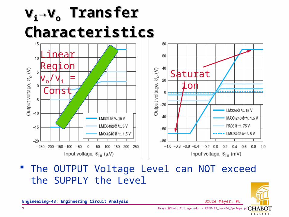
vvii→v→voo Transfer Characteristics Transfer Characteristics
Saturation
The OUTPUT Voltage Level can NOT exceed the SUPPLY the Level
LinearRegionvo/vi = Const

[email protected] • ENGR-43_Lec-04_Op-Amps.ppt10
Bruce Mayer, PE Engineering-43: Engineering Circuit Analysis
Unity Gain BufferUnity Gain Buffer
Controlling Variable = IRV iin
Solve For Buffer Gain
O
iOO
is
out A
RARRV
Vrecall
1
1 Thus The Amplification
1S
outO V
VA
Op-Amp BUFFER GAINLM324 0.99999LMC6492 0.9998MAX4240 0.99995
0 inOOis VAIRIRV :KVL
0 inOO VAIRoutV- :KVL

[email protected] • ENGR-43_Lec-04_Op-Amps.ppt11
Bruce Mayer, PE Engineering-43: Engineering Circuit Analysis
The Ideal OpAmpThe Ideal OpAmp The IDEAL
Characteristics• Ro = 0
• Ri =
• A = The Consequences
of Ideality
][12:@ 133 VVVV S
i
i
vvA
0 iiRi
vvAvR oo 0

[email protected] • ENGR-43_Lec-04_Op-Amps.ppt12
Bruce Mayer, PE Engineering-43: Engineering Circuit Analysis
Voltage FollowerVoltage Follower The Voltage Follower
• Also Called Unity Gain Buffer (UGB) from Before
Connection w/o Buffer Buffered Connection
svv
vv
vvO
SO vv
The SOURCE Supplies The Power
The Source Supplies NO Power (the OpAmp does it)
Usefulness of UGB
SO vv sSO iRvv

[email protected] • ENGR-43_Lec-04_Op-Amps.ppt13
Bruce Mayer, PE Engineering-43: Engineering Circuit Analysis
Inverting Inverting OpAmp CktOpAmp Ckt
Determine Voltage Gain, G = Vout/Vin
Start with Ao
Now From Input R
Apply KCL at v-
Finally The Gain
0v
0v
0i
0
v
vvAo
0 iiRi
000
21
R
V
R
V outs
1
2
R
R
V
VG
s
out
Next: Examine Ckt w/o Ideality Assumption

[email protected] • ENGR-43_Lec-04_Op-Amps.ppt14
Bruce Mayer, PE Engineering-43: Engineering Circuit Analysis
Replace OpAmp w/ Linear ModelReplace OpAmp w/ Linear Model
Consider Again the Inverting OpAmp Circuit
Draw the Linear Model
1. Identify the Op Amp Nodes
v
v
ov

[email protected] • ENGR-43_Lec-04_Op-Amps.ppt15
Bruce Mayer, PE Engineering-43: Engineering Circuit Analysis
Drawing the OpAmp Linear ModelDrawing the OpAmp Linear Model
2. Redraw the circuit cutting out the Op Amp
3. Draw components of linear OpAmp (on the circuit of step-2)
v
v
ovv
v
ov
OR
( )A v v
iR

[email protected] • ENGR-43_Lec-04_Op-Amps.ppt16
Bruce Mayer, PE Engineering-43: Engineering Circuit Analysis
Drawing the OpAmp Linear ModelDrawing the OpAmp Linear Model
4. UNTANGLE as Needed
2R
v
v
The BEFORE & AFTER
2R

[email protected] • ENGR-43_Lec-04_Op-Amps.ppt17
Bruce Mayer, PE Engineering-43: Engineering Circuit Analysis
NonIdeal Inverting AmpNonIdeal Inverting Amp Replace the OpAmp with
the LINEAR Model• Label Nodes for Tracking
Draw The Linear Equivalent For Op-amp
Note the External Component Branches
b - a
b - d

[email protected] • ENGR-43_Lec-04_Op-Amps.ppt18
Bruce Mayer, PE Engineering-43: Engineering Circuit Analysis
NonIdeal Inverting Amp cont.NonIdeal Inverting Amp cont. On The LINEAR Model
Connect The External Components
ReDraw Ckt for Increased Clarity
Now Must Sweat the Details
2R

[email protected] • ENGR-43_Lec-04_Op-Amps.ppt19
Bruce Mayer, PE Engineering-43: Engineering Circuit Analysis
NonIdeal Inverting Amp cont.NonIdeal Inverting Amp cont. Node Analysis
• Note GND Node
Controlling Variable In Terms Of Node Voltages
The 2 Eqns in Matrix Form
2

[email protected] • ENGR-43_Lec-04_Op-Amps.ppt20
Bruce Mayer, PE Engineering-43: Engineering Circuit Analysis
Inverting Amp – Invert MatrixInverting Amp – Invert Matrix Use Matrix Inversion to Solve 2 Eqns in 2 Unknowns
• Very Useful for 3 Eqn/Unknwn Systems as well
– e.g., http://www.wikipedia.org/wiki/Matrix_inversion
The Matrix Determinant
Solve for vo

[email protected] • ENGR-43_Lec-04_Op-Amps.ppt21
Bruce Mayer, PE Engineering-43: Engineering Circuit Analysis
Inverting Amp – Invert Matrix contInverting Amp – Invert Matrix cont Then the System Gain
Typical Practical Values for the Resistances• R1 = 1 kΩ R2 = 5 kΩ
Then the Real-World Gain
9996994.4S
O
v
v
Recall The Ideal Case for A→; Then The Eqn at top
0000.5
1
15
1
15lim
2
oA
S
O
RRAKv
v

[email protected] • ENGR-43_Lec-04_Op-Amps.ppt22
Bruce Mayer, PE Engineering-43: Engineering Circuit Analysis
Compare Ideal vs. NonIdealCompare Ideal vs. NonIdeal
Ideal Assumptions Gain for Real Case• Replace Op-amp By Linear
Model, Solve The Resulting Circuit With Dep. Sources
0i
0v
0v
0 iiRi
0 vvA

[email protected] • ENGR-43_Lec-04_Op-Amps.ppt23
Bruce Mayer, PE Engineering-43: Engineering Circuit Analysis
Compare Ideal vs. NonIdeal cont.Compare Ideal vs. NonIdeal cont.
Ideal Case at Inverting Terminal Gain for NonIdeal Case
0i
1
2
21
000
R
R
v
v
R
v
R
v
S
OOS
The Ideal Op-amp Assumption Provides an Excellent Real-World Approximation.
Unless Forced to do Otherwise We Will Always Use the IDEAL Model

[email protected] • ENGR-43_Lec-04_Op-Amps.ppt24
Bruce Mayer, PE Engineering-43: Engineering Circuit Analysis
Example Example Differential Amp Differential Amp KCL At Inverting Term
KCL at NONinvertingTerminal
Assume Ideal OpAmp
By The KCLs
1
2
1
1
21
1
2
1
2 110 vvR
R
R
Rv
R
Rv
R
Rvi O
243
42
43
40 vRR
Rvv
RR
Rvi
A simple Voltage Divider

[email protected] • ENGR-43_Lec-04_Op-Amps.ppt25
Bruce Mayer, PE Engineering-43: Engineering Circuit Analysis
Example Example Differential Amp Differential Amp contcont
Then in The Ideal Case
Now Set External Rs• R4 = R2
• R3 = R1
Subbing the Rs Into the vo Eqn
)( 121
2 vvR
RvO

[email protected] • ENGR-43_Lec-04_Op-Amps.ppt26
Bruce Mayer, PE Engineering-43: Engineering Circuit Analysis
Ex. Precision Diff V-Gain CktEx. Precision Diff V-Gain Ckt Find vo
Assume Ideal OpAmp• Which Voltages are Set?
• What Voltages Are Also Known Due To Infinite Gain Assumption?
2v
1v
2v
0i2211 , vvvv
• Now Use The Infinite Resistance Assumption
CAUTION: There could be currents flowing INTO or OUT of the OpAmps

[email protected] • ENGR-43_Lec-04_Op-Amps.ppt27
Bruce Mayer, PE Engineering-43: Engineering Circuit Analysis
Ex. Precision Diff V-Gain Ckt contEx. Precision Diff V-Gain Ckt cont The Ckt Reduces To Fig. at Right
KCL at v1
KCL at v2
1v
2v
av
Eliminate va Using The above Eqns and Solve for vo in terms of v1 & v2
• Note the increased Gain over Diff Amp
GRRRRRR 21212 21 OpAmpCurrent

[email protected] • ENGR-43_Lec-04_Op-Amps.ppt28
Bruce Mayer, PE Engineering-43: Engineering Circuit Analysis
NONinverting Amp - IdealNONinverting Amp - Ideal
Ideal Assumptions• Infinite Gain
Since i- = 0 Arrive at “Inverse Voltage Divider”
vv
0i
R 2
R 1
ivv
0v
• Infinite Ri with v+ = v1
11 vvvv
ii vR
RRvv
RR
Rv
1
2100
21
1

[email protected] • ENGR-43_Lec-04_Op-Amps.ppt29
Bruce Mayer, PE Engineering-43: Engineering Circuit Analysis
Example Example Find I Find Ioo for Ideal OpAmp for Ideal OpAmp
Ideal Assumptions KCL at v-
0 iiRi
VvvA 12
Vv 12
0 iRi
Vv 12
VVkk
Vo
o 8402
12
12
12
mAk
VI oO 4.8
10

[email protected] • ENGR-43_Lec-04_Op-Amps.ppt30
Bruce Mayer, PE Engineering-43: Engineering Circuit Analysis
Find G & RFind G & Rinin for NonIdeal Case for NonIdeal Case
Determine Equivalent Circuit Using Linear Model For Op-Amp
iR
v
v
OvOR
)( vvA
Add Input Source-V
iR
v
v
OvOR
)( vvA1v
The OpAmp Model

[email protected] • ENGR-43_Lec-04_Op-Amps.ppt31
Bruce Mayer, PE Engineering-43: Engineering Circuit Analysis
Find G & RFind G & Rinin for NonIdeal Case cont for NonIdeal Case cont The Equivalent Circuit for
Mesh Analysis Add The External
Components
iR
v
v
OvOR
)( vvA1v
1R
2R
Now Re-draw Circuit To Enhance Clarity • There Are Only Two
Loops
Ov

[email protected] • ENGR-43_Lec-04_Op-Amps.ppt32
Bruce Mayer, PE Engineering-43: Engineering Circuit Analysis
Find G & RFind G & Rinin for NonIdeal Case cont for NonIdeal Case cont Now The Mesh Eqns
• Mesh-1
• Mesh-2
iR
v
v
OvOR
)( vvA1v
1R
2R
)( 21122 iiRiRvO
1
2
The Controlling Variable in Terms of Loop Currents
Eliminating vi
Continue Analysis on Next Slide

[email protected] • ENGR-43_Lec-04_Op-Amps.ppt33
Bruce Mayer, PE Engineering-43: Engineering Circuit Analysis
G & RG & Rinin for NonIdeal Case cont for NonIdeal Case cont The Math Model From
Mesh Analysis
The Input-R and Gain
Then the Model in Matrix Form →
)( 12122 iiRiRvO
1
1
i
vRin
1v
vG O
0)(
)( 1
2
1
211
121 v
i
i
RRRRAR
RRR
Oi
Ov

[email protected] • ENGR-43_Lec-04_Op-Amps.ppt34
Bruce Mayer, PE Engineering-43: Engineering Circuit Analysis
G & RG & Rinin for NonIdeal Case cont for NonIdeal Case cont The Matrix-Inversion Soln
Invert Matrix as Before• Find Determinant, • Adjoint Matrix
0)(
)( 1
1
211
121
2
1 v
RRRRAR
RRR
i
i
Oi
)())(( 112121 RARRRRRRR iO
)()(
)(
211
121
RRRAR
RRRRAdj
i
O
Then the Solution
0)()(
)(1 1
211
121
2
1 v
RRRAR
RRRR
i
i
i
O
Solving for Mesh Currents
121
1 vRRR
i O
)( 1
2
RARi i

[email protected] • ENGR-43_Lec-04_Op-Amps.ppt35
Bruce Mayer, PE Engineering-43: Engineering Circuit Analysis
G & RG & Rinin for NonIdeal Case cont for NonIdeal Case cont The (Long) Expression for The input Resistance
By Mesh Currents
Ov
1121
1211
22111
))(()(
)(
vRARRR
vRRRR
iRRiRv
iO
O
This Looks Ugly• How Can we Simplify?
– Recall A → Ri →

[email protected] • ENGR-43_Lec-04_Op-Amps.ppt36
Bruce Mayer, PE Engineering-43: Engineering Circuit Analysis
G & RG & Rinin for NonIdeal Case cont for NonIdeal Case cont Use A→ in Expression for
Now Since For Op-Amps Ri→ Also, then vo
11
211
1
21
121
1121
1121
1211
)())((
))(())((0
))(()(
vR
RRv
RAR
ARRRv
vARRR
vRARRR
v
vRARRR
vRRRR
v
i
iO
iiO
iOO
Finally then G:
1112121 )())(( RARRARRRRRRRLim iiOA
1
21
1 R
RR
v
vG O
And The Expression for Rin: inR Infinite Input
Resistance is GOOD

[email protected] • ENGR-43_Lec-04_Op-Amps.ppt37
Bruce Mayer, PE Engineering-43: Engineering Circuit Analysis
ExampleExample
Required• Find the expression for vo.
• Indicate where and how Ideal OpAmp assumptions Are Used
Infinite Gain Assumption Fixes v-
Si
Ov
R
+-
Sv
v 0i
v
Svv
Svv
Use Infinite Input Resistance Assumption
Apply KCL to Inverting Input Then Solving
0
R
vvi oS
SSo Rivv
Set Voltages

[email protected] • ENGR-43_Lec-04_Op-Amps.ppt38
Bruce Mayer, PE Engineering-43: Engineering Circuit Analysis
ExampleExample Required
• Draw The Linear Equivalent Circuit
• Write The Loop Equations
1. Locate Nodes
Si
Ov
R
+-
ov
v
v
Ri
RO
2. Place the nodes in linear circuit model

[email protected] • ENGR-43_Lec-04_Op-Amps.ppt39
Bruce Mayer, PE Engineering-43: Engineering Circuit Analysis
Example contExample cont3. Add Remaining
Components to Complete Linear Model
Examine Circuit• Two Loops
• One Current Source
Use Meshes• Mesh-1
• Mesh-2
+-
ov
v
v R
R O
R iiS
A (v + - v - )
1i2i
sii 1
0)()()( _22 vvAiRRiiR OSi
• Controlling Variable
)( 2_ Si iiRvv
DONE• But Could Sub for (v+-v-)
and solve for i2
[email protected] • ENGR-43_Lec-04_Op-Amps.ppt40
Bruce Mayer, PE Engineering-43: Engineering Circuit Analysis
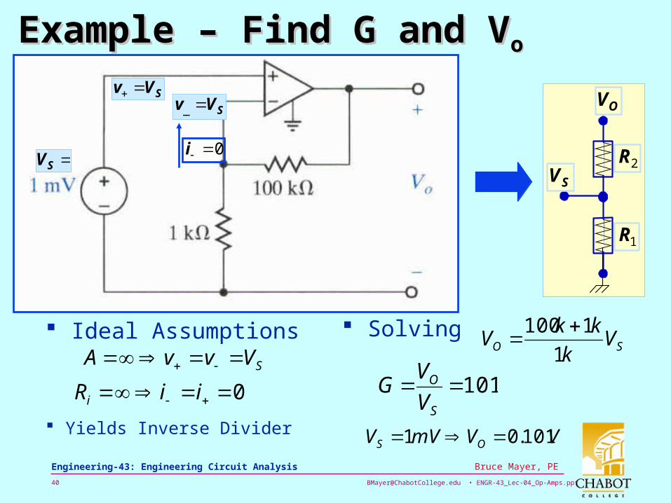
Example – Find G and VExample – Find G and Voo
Ideal Assumptions Solving
0 iiRi
SVvvA
SV
SVv SVv _
0i
Yields Inverse Divider
OV
SV2R
1R
SO Vk
kkV
1
1100
101S
O
V
VG
VVmVV OS 101.01

[email protected] • ENGR-43_Lec-04_Op-Amps.ppt41
Bruce Mayer, PE Engineering-43: Engineering Circuit Analysis
Key to OpAmp Ckt Analysis Key to OpAmp Ckt Analysis IIOAOA
Remember that the “Nose” of the OpAmp “Triangle” can SOURCE or SINK “Infinite” amounts of Current
IOA = ± ∞
|IOA,max| = Isat

[email protected] • ENGR-43_Lec-04_Op-Amps.ppt42
Bruce Mayer, PE Engineering-43: Engineering Circuit Analysis
ComparatorComparator Ideal Comparator and Transfer Characteristic
“Zero-Cross” Detector → Heart of Solid State Relay Cnrtl

[email protected] • ENGR-43_Lec-04_Op-Amps.ppt43
Bruce Mayer, PE Engineering-43: Engineering Circuit Analysis
Example Example OpAmp Based I- OpAmp Based I-MtrMtr Desired Transfer Characteristic = 10V/mA → Find R2
IRR
RGVV IIO
1
21
NON-INVERTING AMPLIFIER
1
21R
RG
IRV II
kR
R
RkR
R
R
mA
V
I
VI
O 911011
102
1
2
1
2
[email protected] • ENGR-43_Lec-04_Op-Amps.ppt44
Bruce Mayer, PE Engineering-43: Engineering Circuit Analysis
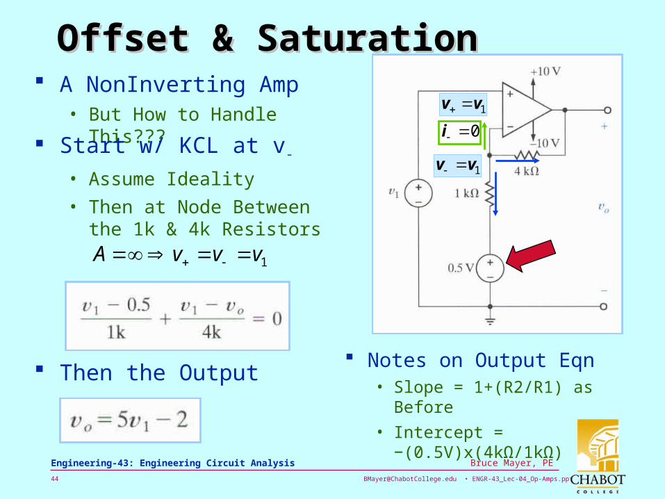
Offset & SaturationOffset & Saturation A NonInverting Amp
• But How to Handle This???
Start w/ KCL at v-
• Assume Ideality
• Then at Node Between the 1k & 4k Resistors
Then the Output Notes on Output Eqn
• Slope = 1+(R2/R1) as Before
• Intercept = −(0.5V)x(4kΩ/1kΩ)
1vv
0i
1vv
1vvvA

[email protected] • ENGR-43_Lec-04_Op-Amps.ppt45
Bruce Mayer, PE Engineering-43: Engineering Circuit Analysis
Example – Offset & SaturationExample – Offset & Saturation
Note how “Offset” Source Generates a Non-Zero Output When v1 = 0
The Transfer Characteristic for This Circuit
IN LINEAR RANGE
−2V Offset
“Saturates” at “Rail” Potential

[email protected] • ENGR-43_Lec-04_Op-Amps.ppt46
Bruce Mayer, PE Engineering-43: Engineering Circuit Analysis
WhiteBoard WorkWhiteBoard Work Let’s Work a Unity Gain Buffer
Problem • Vs = 60mV
• Rs = 29.4 kΩ
• RL = 600 Ω
• Find Load Power WITH and withOUT OpAmp UGB

[email protected] • ENGR-43_Lec-04_Op-Amps.ppt47
Bruce Mayer, PE Engineering-43: Engineering Circuit Analysis
Key to OpAmp Ckt Analysis Key to OpAmp Ckt Analysis IIOAOA
Remember that the “Nose” of the OpAmp “Triangle” can SOURCE or SINK “Infinite” amounts of Current
IOA = ± ∞
[email protected] • ENGR-43_Lec-04_Op-Amps.ppt48
Bruce Mayer, PE Engineering-43: Engineering Circuit Analysis
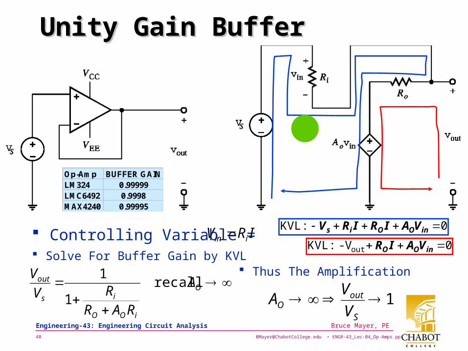
Unity Gain BufferUnity Gain Buffer
Controlling Variable = IRV iin
Solve For Buffer Gain by KVL
O
iOO
is
out A
RARRV
Vrecall
1
1 Thus The Amplification
1S
outO V
VA
0 inOOis VAIRIRV :KVL
Op-Amp BUFFER GAINLM324 0.99999LMC6492 0.9998MAX4240 0.99995
0 inOO VAIRoutV- :KVL