Embed Size (px)
Citation preview
ContentsPage
Safety precautions .................................................21. Introduction....................................................3
1.1 Applicable Model .................................31.2 Restrictions/Cautions...........................4
2. System configurations ...................................52.1 Sample system configuration...............52.2 Group configurations ...........................6
3. Function specifications ..................................73.1 Basic Functions ...................................73.2 Communication protocol
specifications .......................................73.3 Objects.................................................83.4 Relations between objects and control
items ....................................................93.5 Services .............................................103.6 Services per object ............................12
4. Setting for power-on for the first time ..........134.1 Caution ..............................................134.2 Setting up after turning on the power
for the first time ..................................135. Starting up the BAC-HD150 ........................13
5.1 Starting up the BAC-HD150...............135.2 Restarting the BAC-HD150................135.3 Mode of BAC-HD150.........................13
6. Switches and 7-segment LEDs ...................146.1 Swith and LED layout ........................146.2 Switch types.......................................146.3 LED types ..........................................15
7. On-site adjustment steps.............................167.1 On-site adjustment flowchart .............167.2 Preparation for on-site adjustment.....177.3 Step - 1 Initial setting for air
conditioning system ...........................187.4 Step - 2 Test run of air conditioning
system ...............................................197.5 Step - 3 Initial settings for the BAC-
HD150 related items ..........................207.6 Step - 4 Test run of BAC-HD150 .......21
Air-conditioner Control System
BM ADAPTERModel: BAC-HD150 Instruction Book
Thoroughly read this instruction book before use to ensure safety. The users should keep this manual for future reference and refer to it as necessary.BACnet™ is a registered trade mark of ASHRAE (American Society of Heating, Refrigerating, and Air-Conditioning Engineers, INC.).
- 2 -
Safety precautionsBefore using the BAC-HD150, read the Safety Precautions section carefully to ensure proper operation.These safety precautions must be observed by anyone who operates the BAC-HD150.Keep the Instruction Book and Installation Manual for future reference. Make sure both manuals are passed on to any future air condition system users.
WARNING This symbol indicates that failure to follow the instructions exactly as stated poses the risk of serious injury of death.
CAUTION This symbol indicates that failure to follow the instructions exactly as stated poses the risk of injury or damage to the BAC-HD150.
WARNING
CAUTION
The unit must be installed by a dealer or technical representative.Improper installation by an unqualified person may result in electric shock and fire.
Install in a location that is strong enough to withstand the weight of the unit.A weak installation area may cause the unit to fall down, resulting in a personal injury.
Only use specified cables. Securely connect each cable so that the weight of the cable is not applied to the connectors.Loose or improper connections may result in heat generation or fire.
If any abnormality is noticed (e.g., burning smell), stop the operation, turn off the power supply, and contact your dealer or technical representative immediately.Continuing the operation may result in damage to theBAC-HD150, electric shock, or fire.
Ask your dealer or an authorized technician to move or reinstall the BAC-HD150.Improper installation may result in an electric shock or fire.
BAC-HD150 must be disposed of properly.Contact your dealer for proper disposal procedures.
Do not attempt to modify or repair the BAC-HD150.Modification or improper repair may result in electric shock or fire. Consult your dealer when repairs are necessary.
Stop the operation immediately and notify your dealer if the BAC-HD150 does not operate, or when any abnormality is noticed.Continuing the operation may result in damage to the BAC-HD150 or fire.
Do not install the BAC-HD150 where there is a risk of leaking flammable gas.If the leaked gas accumulates around the BAC-HD150, it may ignite and cause an explosion.
Do not wash the BAC-HD150 with water.Doing so may cause an electric shock or malfunction.
Do not use the BAC-HD150 for specialized applications.This product is designed exclusively for use with theMITSUBISHI ELECTRIC building air conditioning controlsystem. The use of this product for other purposes may result in malfunctions.
Do not spray insect sprays or sprays with flammable propellants to the BAC-HD150.To avoid the risk of fire or explosion, do not place flammable sprays near the BAC-HD150 or spray them directly on the BAC-HD150.
Do not apply mechanical shock to BAC-HD 150.
Do not use the BAC-HD150 in an environment high in oil, steam, or sulfuric gas.These substances may have adverse effects on the performance of the BAC-HD150 or damage its parts.
Operate the BAC-HD150 within the temperature range specification.The use of controller outside of its specification may result in serious damage to the BAC-HD150. Be sure to check the temperature range specification in the Installation Manual.
Use a security device such as a VPN router when connecting the BAC-HD150 to the Internet to prevent unauthorized access.If no security devices are installed, the operation settings may be changed by an unauthorized person without the knowledge of the user.
- 3 -
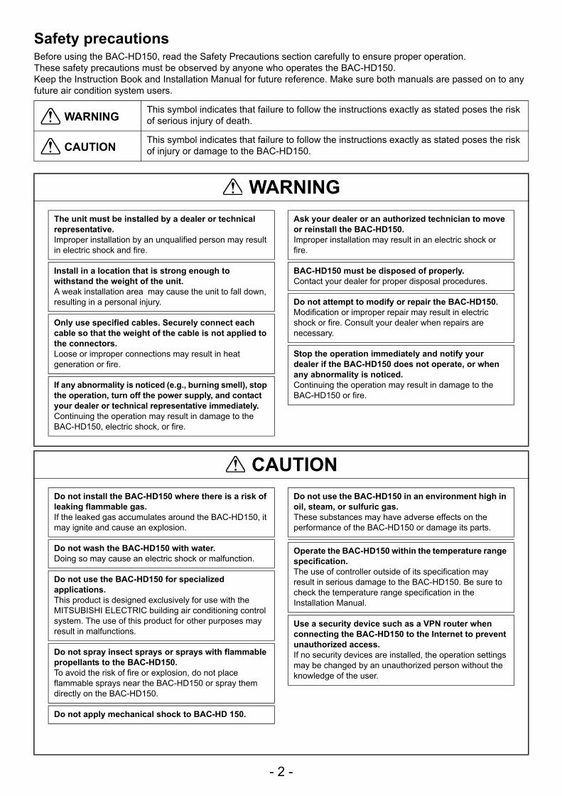
1.1 Applicable ModelBAC-HD150 have functions to monitor and operate air conditioning units (excl. certain models).
Table: Models and available functions
: SupportedX : Not supported
1 Introduction
Model Function (Monitor/Operation)
CITY MULTI
S seriesY SeriesR2 seriesWY seriesWR2 series
LOSSNAYOA Processing unit
A-control unit (Mr Slim) (Requires an adapter)AK-control unit (Mr Slim) xK-control unit xRoom air conditioner (RAC) xAir To Water Booster unit/Air To Water HEX unit x
- 4 -
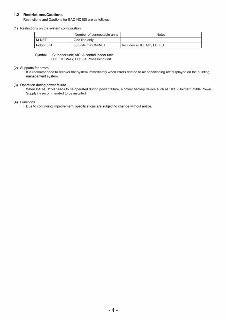
1.2 Restrictions/CautionsRestrictions and Cautions for BAC-HD150 are as follows.
(1) Restrictions on the system configuration
Symbol IC: Indoor unit; AIC: A control indoor unit;LC: LOSSNAY; FU: OA Processing unit
(2) Supports for errors• It is recommended to recover the system immediately when errors related to air conditioning are displayed on the building
management system.
(3) Operation during power failure• When BAC-HD150 needs to be operated during power failure, a power backup device such as UPS (Uninterruptible Power
Supply) is recommended to be installed.
(4) Functions• Due to continuing improvement, specifications are subject to change without notice.
Number of connectable units NotesM-NET One line onlyIndoor unit 50 units max./M-NET Includes all IC, AIC, LC, FU.
- 5 -
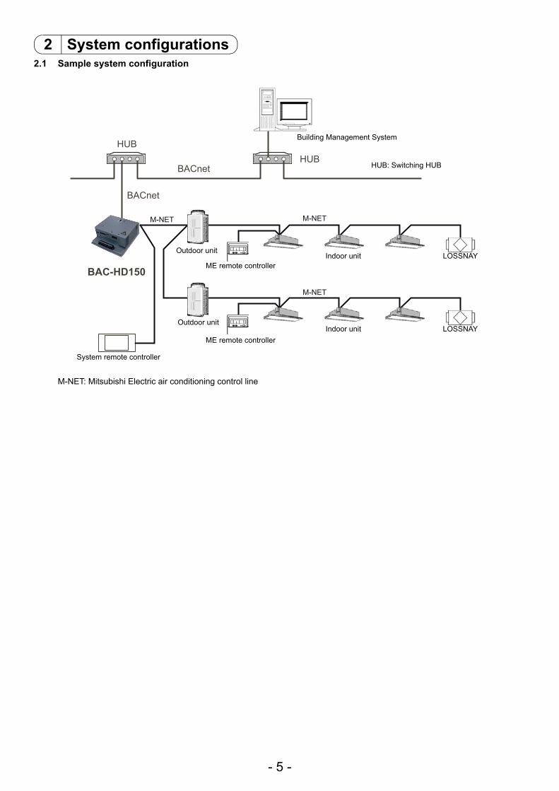
2.1 Sample system configuration
M-NET: Mitsubishi Electric air conditioning control line
2 System configurations
HUB
BACnet
BACnet
M-NET M-NET
M-NET
BAC-HD150
HUB
Building Management System
Outdoor unit
ME remote controllerIndoor unit LOSSNAY
Indoor unit LOSSNAYME remote controller
Outdoor unit
System remote controller
HUB: Switching HUB
- 6 -
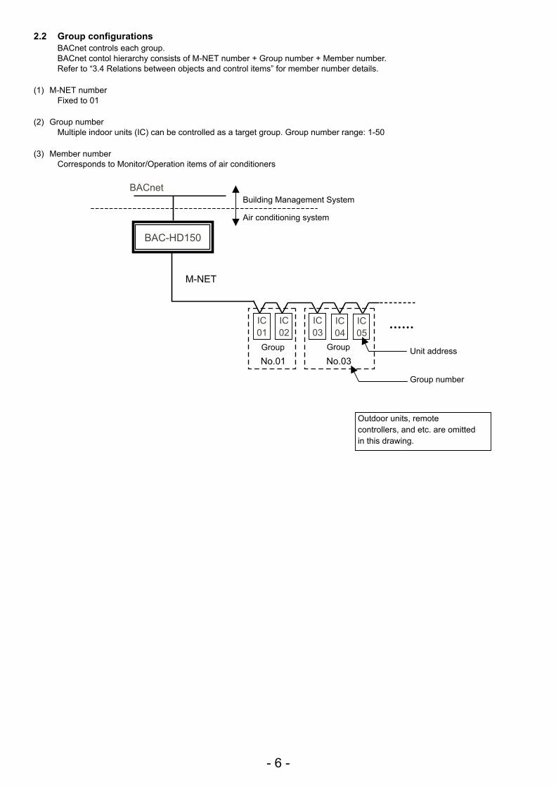
2.2 Group configurationsBACnet controls each group.BACnet contol hierarchy consists of M-NET number + Group number + Member number.Refer to “3.4 Relations between objects and control items” for member number details.
(1) M-NET numberFixed to 01
(2) Group numberMultiple indoor units (IC) can be controlled as a target group. Group number range: 1-50
(3) Member numberCorresponds to Monitor/Operation items of air conditioners
BACnet
IC01
IC02
IC03
IC04
IC05
BAC-HD150
M-NET
No.01 No.03
Building Management System
Air conditioning system
Group Group Unit address
Group number
Outdoor units, remote controllers, and etc. are omitted in this drawing.
- 7 -
3.1 Basic FunctionsBAC-HD150 has functions that communication from an air conditioning system is protocol converted to BACnet communication, that command from a Building Management System is converted and transmitted to an air conditioning system, and that air conditioning system status data is collected and the status change is detected. BAC-HD150 also collects data on air conditioning units operation status and transmits the data upon request from the building management system.Refer to “3.4 Relations between objects and control items” for control item of BAC-HD150.
3.2 Communication protocol specifications(1) General descriptions of protocol
BACnet/IP which applied to ANSI/ASHRAE 135-2004 correspondingly on UDP/IP of Ethernet is used.
Ethernet is a registered trademark of Fuji Xerox, Inc.
(2) Ethernet headerPhysical layer: Ethernet Transmission medium: 10BASE-T
(3) IP headerClass C private address is recommended. (*1) Subnet Mask: 255.255.255.0
*1: Recommended value (range): [192.168.1.1] - [192.168.254.254]Do not use [192.168.0.0] and [192.168.255.255] as a device address.
(4) UDP headerThe default UDP port of unicast and broadcasting is set to 47808 (0xBAC0).
(5) BVLL header (BVLL: BACnet Virtual Link Layer)BVLC type (1 octet) Fixed to 0x81 (BVLL against BACnet/IP)BVLC function (1 octet) Unicast 0x0A
Broadcast 0x0BBVLC length (2 octets) Variable (BVLL header (4 octets) + NPCI data length + APDU data length)
(Typical examples are listed above. Refer to ANSI/ASHRAE 135-2004 for details.)
(6) NPCI (NPCI: Network Layer Protocol Control Information)Version (1 octet) Fixed to 0x01Control (1 octet) Response is received. 0x04
No response 0x00(Typical examples are listed above. Refer to ANSI/ASHRAE 135-2004 for details.)
(7) APDU (APDU: Application Layer Protocol Data Unit)Data: 1024 octets or less
(Refer to ANSI/ASHRAE 135-2004 for details.)
3 Function specifications
Ethernet header IP header UDP header BVLL header NPCI APDU
- 8 -
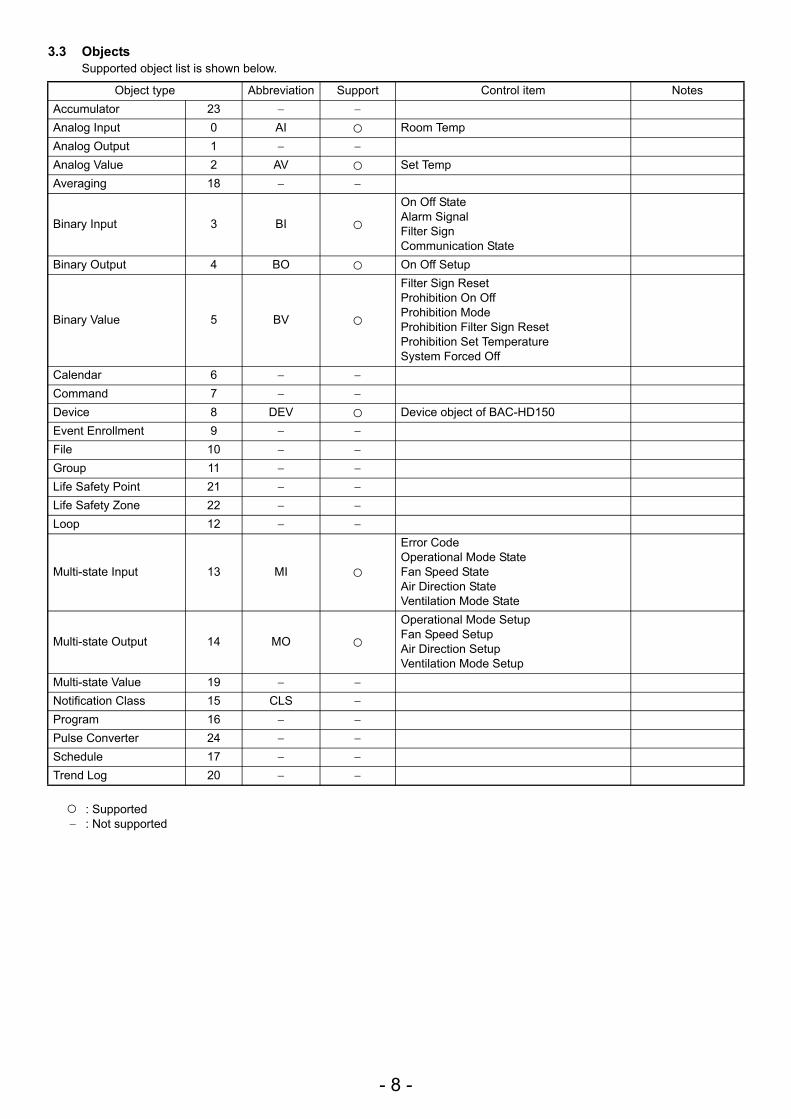
3.3 ObjectsSupported object list is shown below.
: Supported − : Not supported
Object type Abbreviation Support Control item NotesAccumulator 23 − −
Analog Input 0 AI Room TempAnalog Output 1 − −
Analog Value 2 AV Set TempAveraging 18 − −
Binary Input 3 BI
On Off StateAlarm SignalFilter SignCommunication State
Binary Output 4 BO On Off Setup
Binary Value 5 BV
Filter Sign ResetProhibition On OffProhibition ModeProhibition Filter Sign ResetProhibition Set TemperatureSystem Forced Off
Calendar 6 − −
Command 7 − −
Device 8 DEV Device object of BAC-HD150Event Enrollment 9 − −
File 10 − −
Group 11 − −
Life Safety Point 21 − −
Life Safety Zone 22 − −
Loop 12 − −
Multi-state Input 13 MI
Error CodeOperational Mode StateFan Speed StateAir Direction StateVentilation Mode State
Multi-state Output 14 MO
Operational Mode SetupFan Speed SetupAir Direction SetupVentilation Mode Setup
Multi-state Value 19 − −
Notification Class 15 CLS −
Program 16 − −
Pulse Converter 24 − −
Schedule 17 − −
Trend Log 20 − −
- 9 -
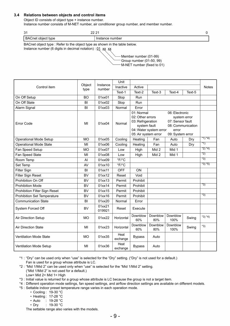
3.4 Relations between objects and control itemsObject ID consists of object type + instance number.Instance number consists of M-NET number, air conditioner group number, and member number.
31 22 21 0
BACnet object type : Refer to the object type as shown in the table below.Instance number (6 digits in decimal notation) : 01 xx xx
*1 : “Dry” can be used only when “use” is selected for the “Dry” setting. (“Dry” is not used for a default.)Fan is used for a group whose attribute is LC.
*2 : “Mid 1/Mid 2” can be used only when “use” is selected for the “Mid 1/Mid 2” setting. (“Mid 1/Mid 2” is not used for a default.)Low< Mid 2< Mid 1< High
*3 : Initial value is returned for a group whose attribute is LC because the group is not a target item.*4 : Different operation mode settings, fan speed settings, and airflow direction settings are available on different models.*5 : Settable indoor preset temperature range varies in each operation mode.
• Cooling : 19-30 °C• Heating : 17-28 °C• Auto : 19-28 °C• Dry : 19-30 °C
The settable range also varies with the models.
BACnet object type Instance number
Control item Object type
Instance number
UnitNotesInactive Active
Text-1 Text-2 Text-3 Text-4 Text-5On Off Setup BO 01xx01 Stop RunOn Off State BI 01xx02 Stop RunAlarm Signal BI 01xx03 Normal Error
Error Code MI 01xx04 Normal
01: Normal 06: Electronic 02: Other errors system error03: Refrigeration 07: Sensor fault
system fault 08: Communication 04: Water system error error05: Air system error 09: System error
Operational Mode Setup MO 01xx05 Cooling Heating Fan Auto Dry *1) *4)
Operational Mode State MI 01xx06 Cooling Heating Fan Auto Dry *1)
Fan Speed Setup MO 01xx07 Low High Mid 2 Mid 1 *2) *4)
Fan Speed State MI 01xx08 Low High Mid 2 Mid 1 *2)
Room Temp AI 01xx09 °F/°C *3)
Set Temp AV 01xx10 °F/°C *3) *5)
Filter Sign BI 01xx11 OFF ONFilter Sign Reset BV 01xx12 Reset VoidProhibition On Off BV 01xx13 Permit ProhibitProhibition Mode BV 01xx14 Permit Prohibit *3)
Prohibition Filter Sign Reset BV 01xx15 Permit ProhibitProhibition Set Temperature BV 01xx16 Permit Prohibit *3)
Communication State BI 01xx20 Normal Error
System Forced Off BV 01xx21019921 Reset Execute
Air Direction Setup MO 01xx22 Horizontal Downblow 60%
Downblow 80%
Downblow 100% Swing *3) *4)
Air Direction State MI 01xx23 Horizontal Downblow 60%
Downblow 80%
Downblow 100% Swing *3)
Ventilation Mode State MO 01xx35 Heat exchange Bypass Auto
Ventilation Mode Setup MI 01xx36 Heat exchange Bypass Auto
Member number (01-99)Group number (01-50, 99)M-NET number (fixed to 01)
- 10 -
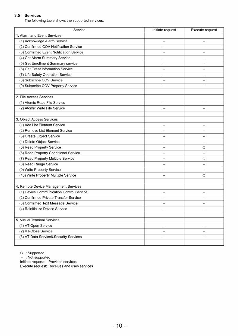
3.5 ServicesThe following table shows the supported services.
: Supported − : Not supportedInitiate request: Provides servicesExecute request: Receives and uses services
Service Initiate request Execute request1. Alarm and Event Services
(1) Acknowlege Alarm Service − −
(2) Confirmed COV Notification Service − −
(3) Confirmed Event Notification Service − −
(4) Get Alarm Summary Service − −
(5) Get Enrollment Summary service − −
(6) Get Event Information Service − −
(7) Life Safety Operation Service − −
(8) Subscribe COV Service − −
(9) Subscribe COV Property Service − −
2. File Access Services(1) Atomic Read File Service − −
(2) Atomic Write File Service − −
3. Object Access Services(1) Add List Element Service − −
(2) Remove List Element Service − −
(3) Create Object Service − −
(4) Delete Object Service − −
(5) Read Property Service −
(6) Read Property Conditional Service − −
(7) Read Property Multiple Service −
(8) Read Range Service − −
(9) Write Property Service −
(10) Write Property Multiple Service −
4. Remote Device Management Services(1) Device Communication Control Service − −
(2) Confirmed Private Transfer Service − −
(3) Confirmed Text Message Service − −
(4) Reinitialize Device Service − −
5. Virtual Terminal Services(1) VT-Open Service − −
(2) VT-Close Service − −
(3) VT-Data Service6.Security Services − −
- 11 -
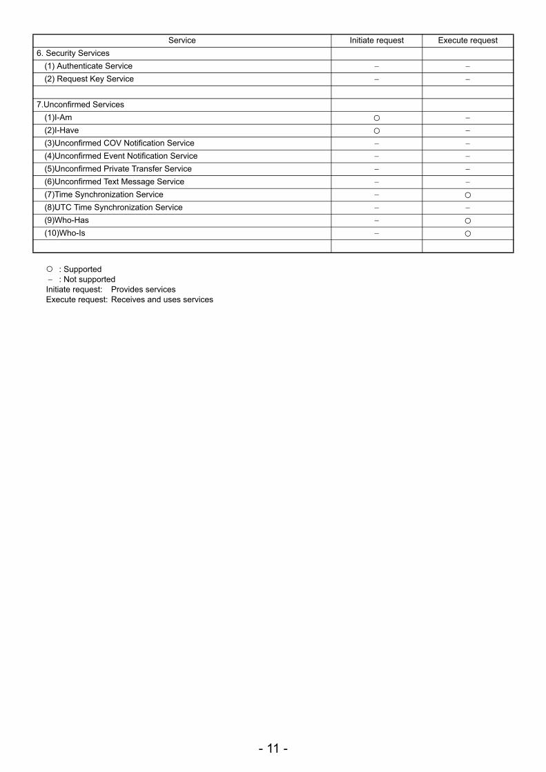
: Supported − : Not supportedInitiate request: Provides servicesExecute request: Receives and uses services
Service Initiate request Execute request6. Security Services
(1) Authenticate Service − −
(2) Request Key Service − −
7.Unconfirmed Services(1)I-Am −
(2)I-Have −
(3)Unconfirmed COV Notification Service − −
(4)Unconfirmed Event Notification Service − −
(5)Unconfirmed Private Transfer Service − −
(6)Unconfirmed Text Message Service − −
(7)Time Synchronization Service −
(8)UTC Time Synchronization Service − −
(9)Who-Has −
(10)Who-Is −
- 12 -
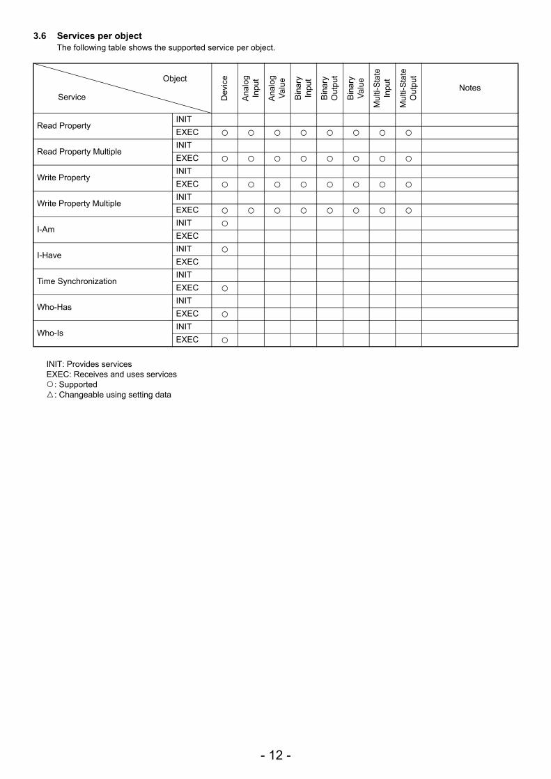
3.6 Services per objectThe following table shows the supported service per object.
INIT: Provides servicesEXEC: Receives and uses services
: Supported: Changeable using setting data
Object
Service Dev
ice
Ana
log
Inpu
t
Ana
log
Valu
e
Bin
ary
Inpu
t
Bin
ary
Out
put
Bin
ary
Valu
e
Mul
ti-St
ate
Inpu
t
Mul
ti-St
ate
Out
put
Notes
Read PropertyINITEXEC
Read Property Multiple INITEXEC
Write PropertyINITEXEC
Write Property MultipleINITEXEC
I-AmINITEXEC
I-HaveINITEXEC
Time SynchronizationINITEXEC
Who-HasINITEXEC
Who-IsINITEXEC
- 13 -
4.1 CautionBACnet LAN IP address for BAC-HD150 is set to “192.168.1.254” at factory setting.The address may overlap one of the addresses that are assigned to other devices connected to BACnet. When turning on the power for the first time after installation, turn on the power with the BACnet LAN cable with BAC-HD150 disconnected. If an address overlaps any of the addresses that are assigned to other devices, BACnet communication cannot be performed properly via BAC-HD150 or other devices.Connect the LAN cable for BAC-HD150 to BACnet after IP address is set by using BAC-HD150 Setting Tool (abbreviated to Setting Tool below).
4.2 Setting up after turning on the power for the first timeMake initial setting using Setting Tool after the power to BAC-HD150 is turned on.Refer to the Instruction Book that came with Setting Tool for details about Initial Setting.
5.1 Starting up the BAC-HD150 BAC-HD150 starts up when the power is turned on.BACnet communication and M-NET communication are performed after startup.
5.2 Restarting the BAC-HD150BAC-HD150 restarts when SW403 is pressed.
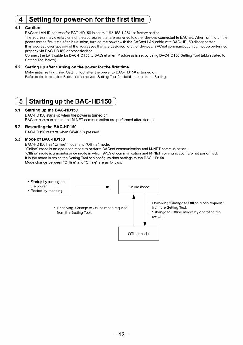
5.3 Mode of BAC-HD150 BAC-HD150 has “Online” mode and “Offline” mode.“Online” mode is an operation mode to perform BACnet communication and M-NET communication.“Offline” mode is a maintenance mode in which BACnet communication and M-NET communication are not performed.It is the mode in which the Setting Tool can configure data settings to the BAC-HD150.Mode change between “Online” and “Offline” are as follows.
4 Setting for power-on for the first time
5 Starting up the BAC-HD150
• Startup by turning on the power
• Restart by resettingOnline mode
Offline mode
• Receiving “Change to Online mode request ” from the Setting Tool.
• Receiving “Change to Offline mode request ” from the Setting Tool.
• “Change to Offline mode” by operating the switch.
- 14 -
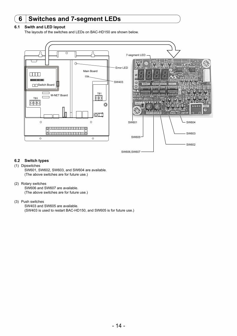
6.1 Swith and LED layoutThe layouts of the switches and LEDs on BAC-HD150 are shown below.
6.2 Switch types(1) Dipswitches
SW601, SW602, SW603, and SW604 are available.(The above switches are for future use.)
(2) Rotary switchesSW606 and SW607 are available.(The above switches are for future use.)
(3) Push switchesSW403 and SW605 are available.(SW403 is used to restart BAC-HD150, and SW605 is for future use.)
6 Switches and 7-segment LEDs
7-segment LED
SW604
SW603
SW602
SW601
SW403
Error LED
SW605
SW606,SW607
Switch Board
Main Board
TB1
TB3M-NET Board
- 15 -
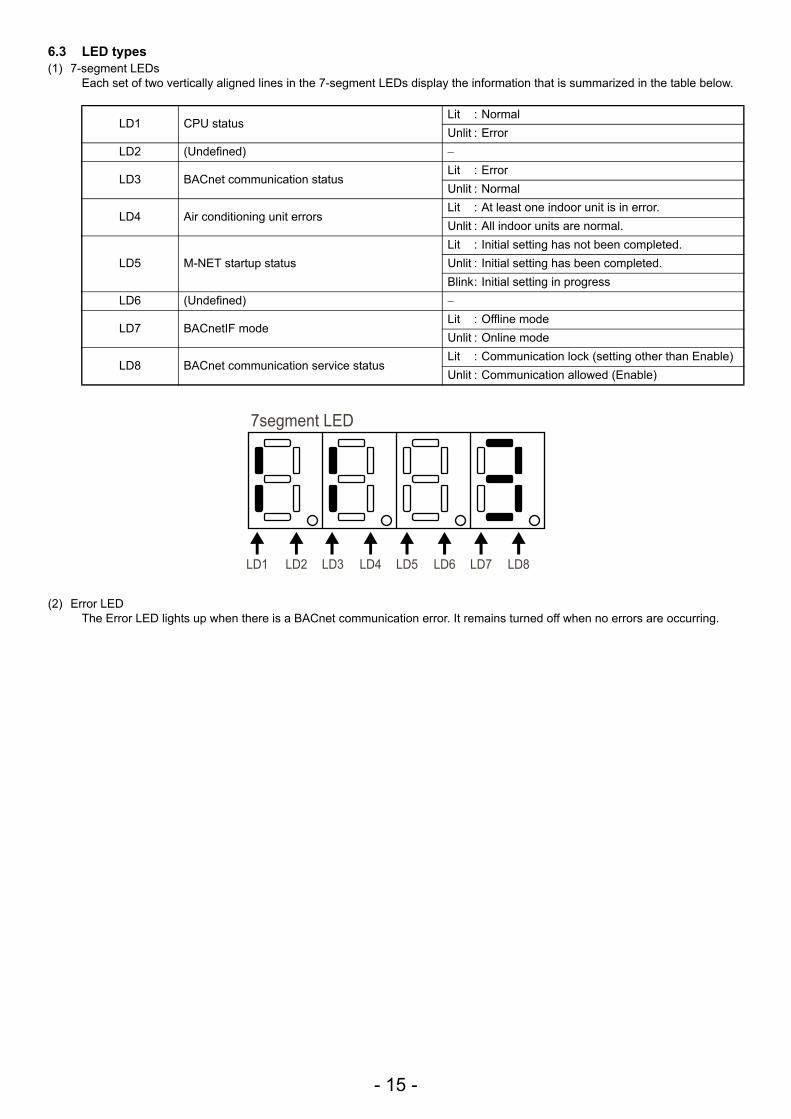
6.3 LED types(1) 7-segment LEDs
Each set of two vertically aligned lines in the 7-segment LEDs display the information that is summarized in the table below.
(2) Error LEDThe Error LED lights up when there is a BACnet communication error. It remains turned off when no errors are occurring.
LD1 CPU statusLit : NormalUnlit : Error
LD2 (Undefined) −
LD3 BACnet communication statusLit : ErrorUnlit : Normal
LD4 Air conditioning unit errorsLit : At least one indoor unit is in error.Unlit : All indoor units are normal.
LD5 M-NET startup statusLit : Initial setting has not been completed.Unlit : Initial setting has been completed.Blink: Initial setting in progress
LD6 (Undefined) −
LD7 BACnetIF modeLit : Offline modeUnlit : Online mode
LD8 BACnet communication service statusLit : Communication lock (setting other than Enable)Unlit : Communication allowed (Enable)
LD1
7segment LED
LD2 LD3 LD4 LD5 LD6 LD7 LD8
- 16 -
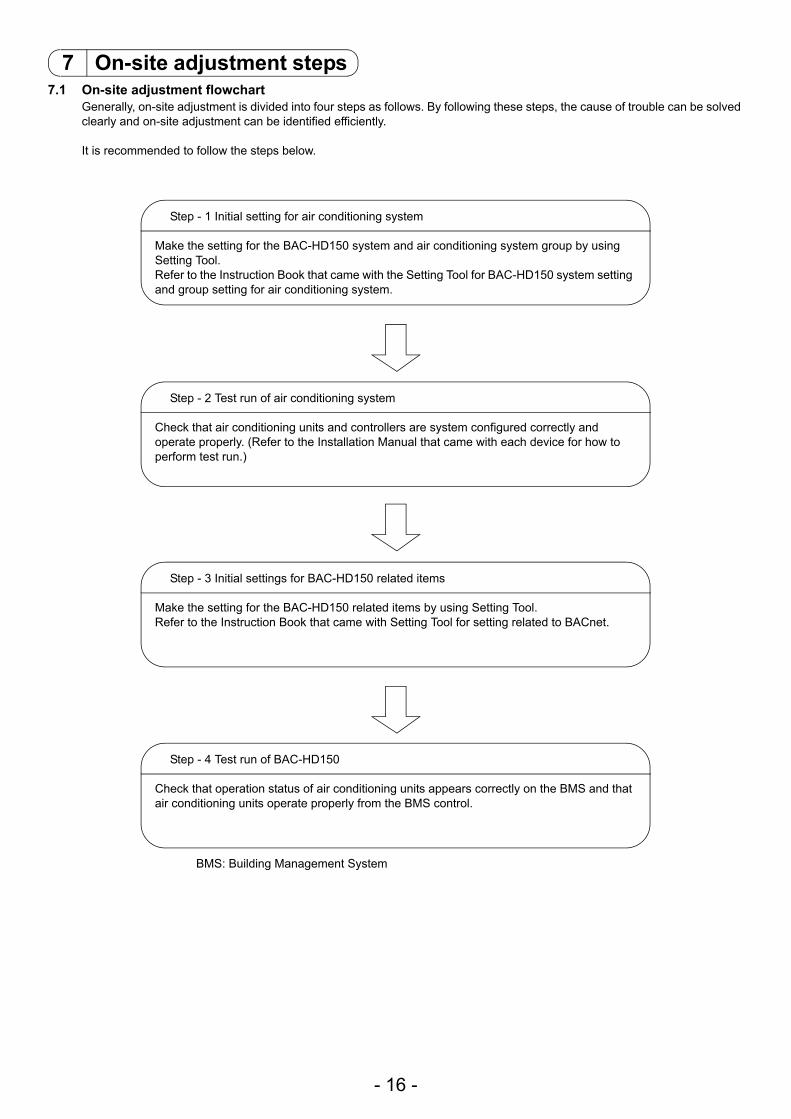
7.1 On-site adjustment flowchartGenerally, on-site adjustment is divided into four steps as follows. By following these steps, the cause of trouble can be solved clearly and on-site adjustment can be identified efficiently.
It is recommended to follow the steps below.
7 On-site adjustment steps
Step - 1 Initial setting for air conditioning system
Make the setting for the BAC-HD150 system and air conditioning system group by using Setting Tool.Refer to the Instruction Book that came with the Setting Tool for BAC-HD150 system setting and group setting for air conditioning system.
Step - 2 Test run of air conditioning system
Check that air conditioning units and controllers are system configured correctly and operate properly. (Refer to the Installation Manual that came with each device for how to perform test run.)
Step - 3 Initial settings for BAC-HD150 related items
Make the setting for the BAC-HD150 related items by using Setting Tool.Refer to the Instruction Book that came with Setting Tool for setting related to BACnet.
Step - 4 Test run of BAC-HD150
Check that operation status of air conditioning units appears correctly on the BMS and that air conditioning units operate properly from the BMS control.
BMS: Building Management System
- 17 -
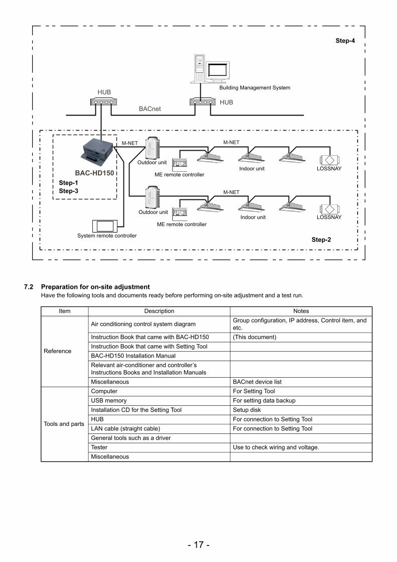
7.2 Preparation for on-site adjustmentHave the following tools and documents ready before performing on-site adjustment and a test run.
Item Description Notes
Reference
Air conditioning control system diagram Group configuration, IP address, Control item, and etc.
Instruction Book that came with BAC-HD150 (This document)Instruction Book that came with Setting ToolBAC-HD150 Installation ManualRelevant air-conditioner and controller’s Instructions Books and Installation ManualsMiscellaneous BACnet device list
Tools and parts
Computer For Setting ToolUSB memory For setting data backupInstallation CD for the Setting Tool Setup diskHUB For connection to Setting ToolLAN cable (straight cable) For connection to Setting ToolGeneral tools such as a driverTester Use to check wiring and voltage.Miscellaneous
HUB HUB
BACnet
M-NET M-NET
M-NET
BAC-HD150
Step-1
Step-4
Step-2
Step-3
Building Management System
Outdoor unit
ME remote controllerIndoor unit LOSSNAY
System remote controller
Outdoor unit
ME remote controllerIndoor unit LOSSNAY
- 18 -
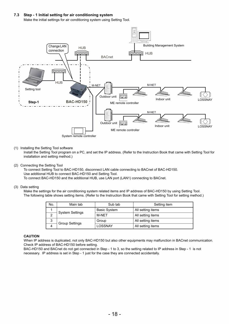
7.3 Step - 1 Initial setting for air conditioning systemMake the initial settings for air conditioning system using Setting Tool.
(1) Installing the Setting Tool softwareInstall the Setting Tool program on a PC, and set the IP address. (Refer to the Instruction Book that came with Setting Tool for installation and setting method.)
(2) Connecting the Setting ToolTo connect Setting Tool to BAC-HD150, disconnect LAN cable connecting to BACnet of BAC-HD150.Use additional HUB to connect BAC-HD150 and Setting Tool.To connect BAC-HD150 and the additional HUB, use LAN port (LAN1) connecting to BACnet.
(3) Data settingMake the settings for the air conditioning system related items and IP address of BAC-HD150 by using Setting Tool.The following table shows setting items. (Refer to the Instruction Book that came with Setting Tool for setting method.)
CAUTIONWhen IP address is duplicated, not only BAC-HD150 but also other equipments may malfunction in BACnet communication. Check IP address of BAC-HD150 before setting.BAC-HD150 and BACnet do not get connected in Step - 1 to 3, so the setting related to IP address in Step - 1 is not necessary. IP address is set in Step - 1 just for the case they are connected accidentally.
No. Main tab Sub tab Setting item1
System SettingsBasic System All setting items
2 M-NET All setting items3
Group SettingsGroup All setting items
4 LOSSNAY All setting items
HUB
HUB
HUB BACnet
M-NET M-NET
M-NET
BAC-HD150
Step-1
Building Management System
Outdoor unit
ME remote controllerIndoor unit LOSSNAY
System remote controller
Outdoor unit
ME remote controllerIndoor unit LOSSNAY
Change LAN connection
Setting tool
- 19 -
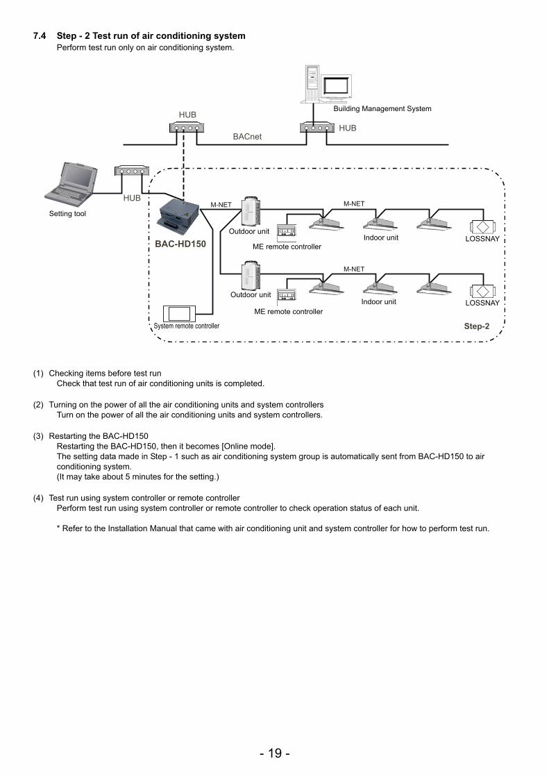
7.4 Step - 2 Test run of air conditioning systemPerform test run only on air conditioning system.
(1) Checking items before test runCheck that test run of air conditioning units is completed.
(2) Turning on the power of all the air conditioning units and system controllersTurn on the power of all the air conditioning units and system controllers.
(3) Restarting the BAC-HD150Restarting the BAC-HD150, then it becomes [Online mode].The setting data made in Step - 1 such as air conditioning system group is automatically sent from BAC-HD150 to air conditioning system.(It may take about 5 minutes for the setting.)
(4) Test run using system controller or remote controllerPerform test run using system controller or remote controller to check operation status of each unit.
* Refer to the Installation Manual that came with air conditioning unit and system controller for how to perform test run.
HUB
HUB
HUB BACnet
M-NET M-NET
M-NET
BAC-HD150
Step-2
Building Management System
Outdoor unit
ME remote controllerIndoor unit LOSSNAY
System remote controller
Outdoor unit
ME remote controllerIndoor unit LOSSNAY
Setting tool
- 20 -
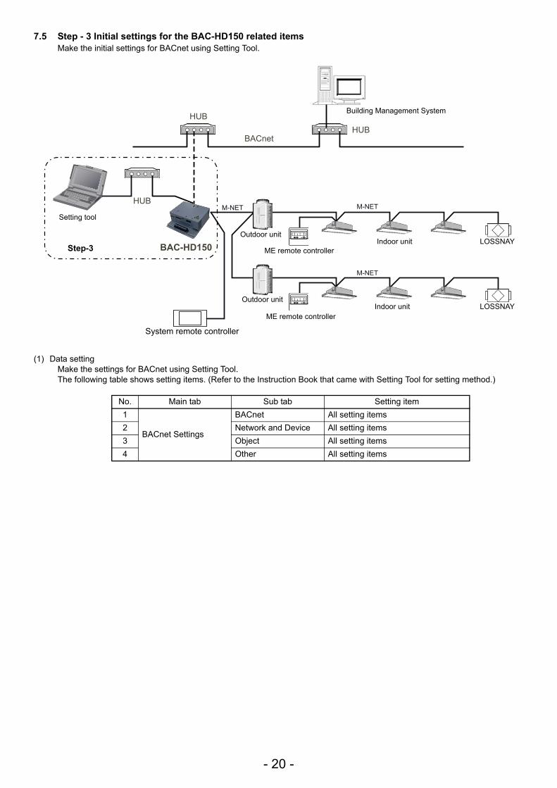
7.5 Step - 3 Initial settings for the BAC-HD150 related itemsMake the initial settings for BACnet using Setting Tool.
(1) Data settingMake the settings for BACnet using Setting Tool.The following table shows setting items. (Refer to the Instruction Book that came with Setting Tool for setting method.)
No. Main tab Sub tab Setting item1
BACnet Settings
BACnet All setting items2 Network and Device All setting items3 Object All setting items4 Other All setting items
HUB
HUB
HUB BACnet
M-NET M-NET
M-NET
BAC-HD150
Step-3
Building Management System
Outdoor unit
ME remote controllerIndoor unit LOSSNAY
System remote controller
Outdoor unit
ME remote controllerIndoor unit LOSSNAY
Setting tool
- 21 -
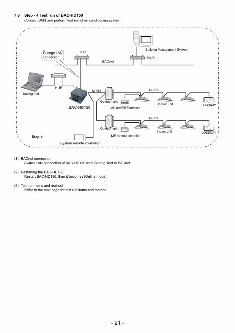
7.6 Step - 4 Test run of BAC-HD150Connect BMS and perform test run of air conditioning system.
(1) BACnet connectionSwitch LAN connection of BAC-HD150 from Setting Tool to BACnet.
(2) Restarting the BAC-HD150Restart BAC-HD150, then it becomes [Online mode].
(3) Test run items and methodRefer to the next page for test run items and method.
HUB
HUB
HUB BACnet
M-NET M-NET
M-NET
BAC-HD150
Step-4
Building Management System
Outdoor unit
ME remote controllerIndoor unit LOSSNAY
System remote controller
Outdoor unit
ME remote controllerIndoor unit LOSSNAY
Setting tool
Change LAN connection
- 22 -
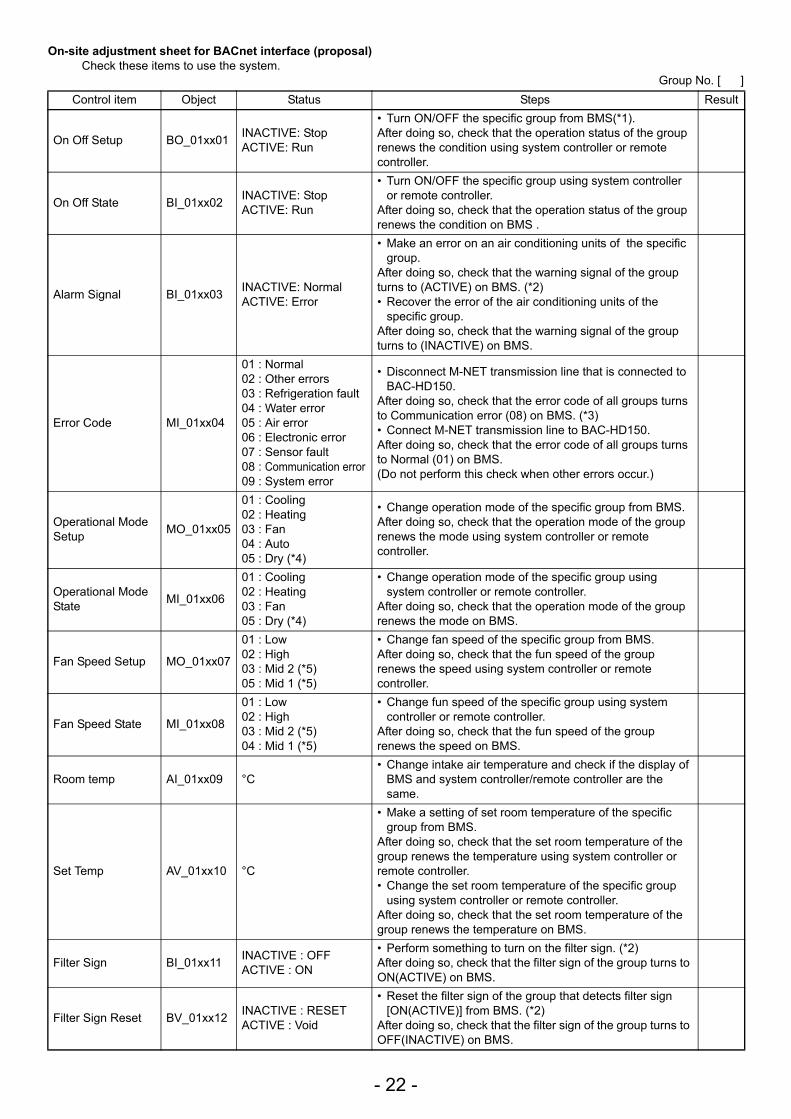
On-site adjustment sheet for BACnet interface (proposal)Check these items to use the system.
Group No. [ ]Control item Object Status Steps Result
On Off Setup BO_01xx01 INACTIVE: StopACTIVE: Run
• Turn ON/OFF the specific group from BMS(*1).After doing so, check that the operation status of the group renews the condition using system controller or remote controller.
On Off State BI_01xx02 INACTIVE: StopACTIVE: Run
• Turn ON/OFF the specific group using system controller or remote controller.
After doing so, check that the operation status of the group renews the condition on BMS .
Alarm Signal BI_01xx03 INACTIVE: NormalACTIVE: Error
• Make an error on an air conditioning units of the specific group.
After doing so, check that the warning signal of the group turns to (ACTIVE) on BMS. (*2)• Recover the error of the air conditioning units of the
specific group.After doing so, check that the warning signal of the group turns to (INACTIVE) on BMS.
Error Code MI_01xx04
01 : Normal02 : Other errors03 : Refrigeration fault04 : Water error05 : Air error06 : Electronic error07 : Sensor fault08 : Communication error09 : System error
• Disconnect M-NET transmission line that is connected to BAC-HD150.
After doing so, check that the error code of all groups turns to Communication error (08) on BMS. (*3)• Connect M-NET transmission line to BAC-HD150.After doing so, check that the error code of all groups turns to Normal (01) on BMS.(Do not perform this check when other errors occur.)
Operational Mode Setup MO_01xx05
01 : Cooling02 : Heating03 : Fan04 : Auto05 : Dry (*4)
• Change operation mode of the specific group from BMS.After doing so, check that the operation mode of the group renews the mode using system controller or remote controller.
Operational Mode State MI_01xx06
01 : Cooling02 : Heating03 : Fan05 : Dry (*4)
• Change operation mode of the specific group using system controller or remote controller.
After doing so, check that the operation mode of the group renews the mode on BMS.
Fan Speed Setup MO_01xx07
01 : Low02 : High03 : Mid 2 (*5)05 : Mid 1 (*5)
• Change fan speed of the specific group from BMS.After doing so, check that the fun speed of the group renews the speed using system controller or remote controller.
Fan Speed State MI_01xx08
01 : Low02 : High03 : Mid 2 (*5)04 : Mid 1 (*5)
• Change fun speed of the specific group using system controller or remote controller.
After doing so, check that the fun speed of the group renews the speed on BMS.
Room temp AI_01xx09 °C• Change intake air temperature and check if the display of
BMS and system controller/remote controller are the same.
Set Temp AV_01xx10 °C
• Make a setting of set room temperature of the specific group from BMS.
After doing so, check that the set room temperature of the group renews the temperature using system controller or remote controller.• Change the set room temperature of the specific group
using system controller or remote controller.After doing so, check that the set room temperature of the group renews the temperature on BMS.
Filter Sign BI_01xx11 INACTIVE : OFFACTIVE : ON
• Perform something to turn on the filter sign. (*2)After doing so, check that the filter sign of the group turns to ON(ACTIVE) on BMS.
Filter Sign Reset BV_01xx12 INACTIVE : RESET ACTIVE : Void
• Reset the filter sign of the group that detects filter sign [ON(ACTIVE)] from BMS. (*2)
After doing so, check that the filter sign of the group turns to OFF(INACTIVE) on BMS.
- 23 -
*1: BMS = Building Management System *2: Consult a Mitsubishi personnel for the confirmation method.*3: It can take up to five minutes for an error to be detected.*4: “Dry” can be used only when “use” is selected for the “Dry” setting (“Dry” is not used for a default.)*5: “Mid 1/Mid 2” can be used only when “use” is selected for the “Mid 1/Mid 2” setting. (“Mid 1/Mid 2” is not used for a default.)
Prohibition On Off BV_01xx13 INACTIVE : PermitACTIVE : Prohibit
• Prohibit the remote controller (ON/OFF) of the specific group from BMS.
After doing so, check that the remote controller (ON/OFF) of the group turns to (ACTIVE) via the remote controller. • Permit the remote controller (ON/OFF) of the specific
group from BMS.After doing so, check that the remote controller (ON/OFF) of the group turns to (INACTIVE) via the remote controller.
Prohibition Mode BV_01xx14 INACTIVE : PermitACTIVE : Prohibit
• Operation/checking object is the same as the steps of remote controller (operation mode), but the checking method is the same as the steps of remote controller (ON/OFF).
Prohibition Filter Sign Reset BV_01xx15 INACTIVE : Permit
ACTIVE : Prohibit
• Operation/checking object is the same as the steps of remote controller (filter sign reset), but the checking method is the same as the steps of remote controller (ON/OFF).
Prohibition Set Temperature BV_01xx16 INACTIVE : Permit
ACTIVE : Prohibit
• Operation/checking object is the same as the steps of remote controller (set temperature), but the checking method is the same as the steps of remote controller (ON/OFF).
Communication State BI_01xx20 INACTIVE: Normal
ACTIVE: Error
• Disconnect M-NET transmission line which is connected to BAC-HD150.
After doing so, check that the communication condition of all groups turns to error (ACTIVE) on BMS. (*3)• Connect M-NET transmission line to BAC-HD150.After doing so, check that the error code of all groups turns to Normal (INACTIVE) on BMS.
System Forced Off BV_01xx21BV_019921
INACTIVE: ResetACTIVE: Execute
• Perform a forced stop of the system of the specific group from BMS.
After doing so, check that the air conditioner stops on BMS.
Air Direction Setup MO_01xx22
01 : Horizontal02 : Downblow 60%03 : Downblow 80%04 : Downblow 100%05 : Swing
• Change the air direction of the specific group from BMS.After doing so, check that the air direction of the group renews the direction using system controller or remote controller.
Air Direction State MI_01xx23
01 : Horizontal02 : Downblow 60%03 : Downblow 80%04 : Downblow 100%05 : Swing
• Change the air direction of the specific group using system controller or remote controller.
After doing so, check that the air direction of the group renews the direction on BMS.
Ventilation Mode Setup MO_01xx35
01 : Heat exchange02 : Bypass03 : Auto
• Change the LOSSNAY ventilation mode of the specific group from BMS.
After doing so, check that the LOSSNAY ventilation mode of the group renews the mode using system controller or remote controller.
Ventilation Mode State MI_01xx36
01 : Heat exchange02 : Bypass03 : Auto
• Change the LOSSNAY ventilation mode of the specific group using system controller or remote controller.
After doing so, check that the LOSSNAY ventilation mode of the group renews the mode on BMS.
Control item Object Status Steps Result
HEAD OFFICE: TOKYO BLDG. , 2-7-3, MARUNOUCHI, CHIYODA-KU, TOKYO 100-8310, JAPANAuthorized representative in EU: MITSUBISHI ELECTRIC EUROPE B.V.
HARMAN HOUSE, 1 GEORGE STREET, UXBRIDGE, MIDDLESEX UB8 1QQ, U.K.
WT05542X01Printed in JapanRecycled Paper
WT05542X01Printed in JapanRecycled Paper
Please be sure to put the contact address/telephone number on this manual before handing it to the customer.
This product is designed and intended for use in the residential, commercial and light-industrial environment.
The product at hand is based on the following EU regulations:
• Low Voltage Directive 2006/95/EC• Electromagnetic Compatibility Directive,
2004/108/EC


![AJ- - ESV Teleproductions Graphics/B_AJ... · 2011-02-27 · SP-AJHD150P3 VSD6262 [03150.2] (20K) 15K102ZM-3 Printed in Japan Rear Panel AJ-HD150 SPECIFICATIONS General Power Supply:](https://img.pdfslide.us/doc/110x75/5f802bcb6d42bf3950754236/aj-esv-teleproductions-graphicsbaj-2011-02-27-sp-ajhd150p3-vsd6262-031502.jpg)