Embed Size (px)
Citation preview
APPLICATION NOTE
R01AN2469EJ0113 Rev.1.13 Page 1 of 63 Mar 30, 2018
Bluetooth® Low Energy Protocol Stack GUI Tool Introduction This manual describes the installation, configuration and usage of GUI Tool. The tool controls the Renesas Bluetooth low energy microcontroller RL78/G1D device programmed with Bluetooth Low Energy (BLE) protocol stack (hereafter called BLE software), which used for development of Bluetooth applications.
Target Device RL78/G1D
Related documents The related documents referred in this document might include preliminary versions. However, the preliminary versions are not marked as such.
Document Name Document No.
Bluetooth Low Energy Protocol Stack
User's Manual R01UW0095E
API Reference Manual : Basics R01UW0088E
API Reference Manual : FMP R01UW0089E
API Reference Manual : PXP R01UW0090E
API Reference Manual : HRP R01UW0097E
API Reference Manual : TIP R01UW0106E
API Reference Manual : ANP R01UW0108E
Application Note: rBLE Command Specification R01AN1376E
R01AN2469EJ0113 Rev.1.13
Mar 30, 2018

Bluetooth® Low Energy Protocol Stack GUI Tool
R01AN2469EJ0113 Rev.1.13 Page 2 of 63 Mar 30, 2018
Contents
1. Overview ........................................................................................................................... 3
2. Applicability ...................................................................................................................... 3
3. Restriction ........................................................................................................................ 3
4. Operational Environment ................................................................................................ 3
5. Installation ........................................................................................................................ 3 5.1 Contents ....................................................................................................................................... 3 5.2 Installation Procedure ................................................................................................................ 3
6. Utilization .......................................................................................................................... 4 6.1 Connection of serial interface ................................................................................................... 4 6.2 Launch GUI Tool ......................................................................................................................... 5 6.3 Display of dialog ......................................................................................................................... 6
7. Dialog settings and operations ....................................................................................... 7 7.1 Log Dialog .................................................................................................................................... 7 7.2 Main Dialog .................................................................................................................................. 8
7.2.1 GAP Tab ............................................................................................................................... 10 7.2.2 Peer Device Tab .................................................................................................................. 22 7.2.3 Vendor Specific Tab ........................................................................................................... 32 7.2.4 GATT Tab ............................................................................................................................. 34 7.2.5 Profiles Tab .......................................................................................................................... 40
8. Appendix ......................................................................................................................... 54 8.1 File and Folder Organization.................................................................................................... 54 8.2 Error Messages ......................................................................................................................... 54 8.3 API Quick Reference List ......................................................................................................... 55 8.4 How to use the Direct Test Mode ............................................................................................ 58
8.4.1 Direct Test Mode (Receiver) ............................................................................................... 58 8.4.2 Direct Test Mode (Transmitter) .......................................................................................... 59
8.5 References ................................................................................................................................. 59 8.6 Terminology ............................................................................................................................... 60 8.7 GUI Tool Changes Log ............................................................................................................. 62

Bluetooth® Low Energy Protocol Stack GUI Tool
R01AN2469EJ0113 Rev.1.13 Page 3 of 63 Mar 30, 2018
1. Overview The GUI Tool is an application tool to evaluate APIs: GAP, SM, VS, GATT and Profiles (FMP, PXP, ANP, HRP and TIP), which is provided by BLE software. It transmits and receives the rBLE command or event via serial communication to RL78/G1D device programmed with BLE software in Modem configuration.
This manual describes about GUI Tool installation, configuration and its operation.
For details about the BLE protocol stack APIs, refer to Bluetooth Low Energy Protocol Stack API Reference Manual and detail about rBLE Commands and Events are in the rBLE Command Specification document listed in page 1, this document.
2. Applicability This manual explains about GUI Tool Version 1.12 or later.
3. Restriction This GUI Tool is intended to evaluate the RL78/G1D device with Renesas BLE software. Accordingly, the GUI Tool is not applicable to other purpose.
4. Operational Environment The GUI Tool runs on the following operating environment.
Microsoft Windows 7 SP1 Visual C++ Redistributable for Visual Studio 2012 Update 4
(If not installed in PC, use Microsoft® download link) [Note] GUI tool is a 32-bit application. Please note that even if you are using the 64-bit version of Windows, you shall
install the x86 version of redistributable runtime library (VSU_4\vcredist_x86.exe).
5. Installation 5.1 Contents The compressed GUI Tool includes the following:
• Documents Bluetooth Low Energy Protocol Stack GUI Tool Manual (this document)
• Executable file
5.2 Installation Procedure Create an empty folder in the computer and copy the decompressed GUI Tool to that folder. Check that folder has all copied files and the same organization as shown in section 8.1.

Bluetooth® Low Energy Protocol Stack GUI Tool
R01AN2469EJ0113 Rev.1.13 Page 4 of 63 Mar 30, 2018
6. Utilization 6.1 Connection of serial interface GUI Tool transmits and receives the rBLE Command or Event through serial communication using UART 2-wire connection method(*1) or UART 2-wire with branch connection method(*2) to Renesas Bluetooth Evaluation Board (hereafter called BLE Eval Board). This board is programmed with the Modem configuration and use as target device. Connect PC to the BLE Eval Board via USB cable(*3) as shown in Figure 6-1.
Figure 6-1 The GUI Tool interface setup
[Note] 1. For details about the method of UART 2-wire connection, refer to the Bluetooth Low Energy Protocol Stack User's Manual 5.4.1 UART 2-wire Connection.
2. For details about the method of UART 2-wire with Branch Connection, refer to the Bluetooth Low Energy Protocol Stack User's Manual 5.4.3 UART 2-wire with Branch Connection.
3. If Windows PC requires a device driver for USB UART IC (FT232RL), use FTDI driver link.
USB Cable
Windows PC Target Device Renesas Bluetooth Evaluation Board (Modem configuration)

Bluetooth® Low Energy Protocol Stack GUI Tool
R01AN2469EJ0113 Rev.1.13 Page 5 of 63 Mar 30, 2018
6.2 Launch GUI Tool Double click the GUI Tool icon [rBLE_Tool.exe] in the installed directory to launch this program. The files listed in Table 6-1 are essential to run this GUI application. Thus, make sure all these files locate in the same folder.
Table 6-1 GUI Tool files
File Name Description rBLE_Tool.exe GUI Tool executable program for
Windows PC rBLE_Tool.ini INI file for GUI Tool rBLE_Tool_Err_Msg.tbl Definition file for error message
[Note] If INI file does not exist, automatically create the file after running the GUI Tool.
Once open the GUI Tool application, the Serial port settings Dialog Box Window pop up as shown in Figure 6-2. Select appropriate serial Com Port that connected with BLE Eval Board and set the baud rate. Next click “OK” button for setting confirmation. Then, the Serial port settings Dialog Box Window will be close. If you use the UART 2-wire branch connection method, check "UART 2-wire with Branch Connection" check box.
Figure 6-2 Serial port settings
[Note] Specify the correct baud rate in GUI to match the BLE software baud rate. In the Modem configuration, the default baud rate is 4800bps.

Bluetooth® Low Energy Protocol Stack GUI Tool
R01AN2469EJ0113 Rev.1.13 Page 6 of 63 Mar 30, 2018
6.3 Display of dialog After setting correct baud rate and the serial port setting, GUI Tool will initiate communication to BLE software that run on the RL78/G1D. The GUI Tool application has two dialog boxes: the main dialog as rBLE_Tool and log dialog as Log. They are shown in Figure 6-3.
Figure 6-3 Main dialog and Log dialog
• Main dialog Main dialog transmits a command to BLE software, displays received events parameters from the BLE software, and displays operation state of the local device (BLE Eval Board).
• Log dialog The Log dialog box displays command parameter and event parameter. The specific time stamp displays in each command parameters that transmitted to the BLE software and the event parameters, which received from the BLE software, also embedded with specific time stamp.
Main dialog Log dialog

Bluetooth® Low Energy Protocol Stack GUI Tool
R01AN2469EJ0113 Rev.1.13 Page 7 of 63 Mar 30, 2018
7. Dialog settings and operations For operation and setting this GUI specifically, it is better off to understand Bluetooth Core Specification version 4.2 (known as Bluetooth 4.2). Refer to the web Bluetooth® specification link.
7.1 Log Dialog Log dialog displays Commands and Events for their parameters with local PC time stamp whenever transmit or receive between GUI Tool and BLE software that run on the RL78/G1D.
For easy to differentiate, the commands and events are displayed in different color. The typical Log dialog box is shown in Figure 7-1, and the details are labeled with text boxes.
Figure 7-1 Log dialog
You can switch on or off the Log dialog box by clicking the Hide Log / Show Log button. That button is located in the status bar, at the bottom of Main dialog box, shown in Figure 7-2.
Figure 7-2 Main dialog status bar
Transmitted Command Time Stamp
Command name
Command parameters
Received Event Time Stamp
Event Name
Event Parameters
Switch the display or hide Log dialog box

Bluetooth® Low Energy Protocol Stack GUI Tool
R01AN2469EJ0113 Rev.1.13 Page 8 of 63 Mar 30, 2018
7.2 Main Dialog Main dialog transmits command to BLE software, displays received event parameters from BLE software, and displays operation state of the local device. Main dialog has tab interface. The GUI categorizes those tabs due to the specific functions associated with commands. Command parameters can be set on GUI using text box, check box, drop-down list and/or radio button. There are mainly five categories and they are Generic Access Profile (GAP), Peer Device, Vendor Specific, Generic Attribute Profile (GATT), and Profiles.
Figure 7-3 Main dialog
(1) Generic Access Profile (GAP) It has five sub tabs: Generic, Advertising, Scanning, Security, and White List. Using GAP, you can do advertising, scanning, setting security and including white list.
(2) Peer Device Four sub tabs associate in Peer Device, and they are Connection, Information, Pair/Key Exchange and Remote Keys tab. Using Peer Device tab, you can connect or disconnect Bluetooth devices and paring (bonding). This tab provides about connected remote device information like local name, RSSI value and exchanged key information.
(3) Vendor Specific Using extended functionality, you can do hardware testing through Vendor Specific tab include Rx Test Mode and Tx Test Mode. In addition, it allows setting Bluetooth address as well as Power level for transmitting.
(4) Generic Attribute Profile (GATT) GATT has two sub tabs: Client and Server. In the Client, access Service Discovery, Characteristic Discovery, Read, and Write. In the Server tab, you can set parameters via two group boxes: Server Initiated and Permission Setting. In general, GATT allows to exchange characteristic values by using the handles of characteristics which exposed by the server to the client.
(5) Profiles Find Me, Proximity, Alert Notification, Heart Rate and Time profiles are in this Profile tab. This tab shows interaction between client and server using one or more profiles.
Tabs by respective functions
State display

Bluetooth® Low Energy Protocol Stack GUI Tool
R01AN2469EJ0113 Rev.1.13 Page 9 of 63 Mar 30, 2018
Table 7-1 shows functional summary of each tab on Main dialog.
Table 7-1 Functional summary of each tab
Tab Name Summary GAP Execute GAP and SM commands, which use before connection. Generic Reset, Set name of local device, Get information of local device.
Advertising Setting of Advertising parameters and execute. Scanning Setting of Scan parameters and execute. Display received
Advertising data. Security Local device security setting. White List Add or Remove to White List.
Peer Device Execute GAP and SM commands, which associated connection with peer device.
Connection Connect, disconnect and change connection parameters with remote device.
Information Get information of remote device. Pair / Key Exchange Pairing and Encryption parameters setting
Execute Pairing and Encryption Remote Keys Bonding information management
Vendor Specific Execute the original extended features supported by Renesas GATT Execute GATT Client / Server commands Client Perform GATT Client functions.
Display Remote GATT database Server Perform GATT Server functions
Profiles Execute 5 profiles commands Find Me Perform Find Me Locator / Target functions
Proximity Perform Proximity Monitor / Reporter functions Alert Notification Perform Alert Notification Client / Server functions Heart Rate Perform Heart Rate Collector / Sensor functions Time Perform Time Client / Server functions
[Note] In order to use functions on Profiles tab, enable each profile in the BLE software build with Modem configuration. For details about the profile enable / disable setting of BLE software, refer to the Bluetooth Low Energy Protocol Stack User's Manual.

Bluetooth® Low Energy Protocol Stack GUI Tool
R01AN2469EJ0113 Rev.1.13 Page 10 of 63 Mar 30, 2018
7.2.1 GAP Tab In GAP tab, there are five tabs and indicate the state and role of the local device.
Figure 7-4 GAP tab
The State display is placed in the position shown in Figure 7-4. They are typically Link Layer states: Standby State, Advertising State, Scanning State, Initiating State and Connection State. The state and role will change due to the local device operation. Immediately after starting, the GUI Tool calls RBLE_GAP_Reset. Thus, the state will change from the initial state to the standby state. Depend on the selected function and executing, State Display text box shows the states listed in Table 7-2 Display column. After connection establishment, Role display text box indicates the local device role, either "Master" or "Slave".
Table 7-2 State display
Display State --- Initial state (Prior to serial communication) Standby Standby state Advertising Advertising state Scanning Scanning state Initiating Initiating connection state Connection Already connected
State display
Role display
Place 5 tabs

Bluetooth® Low Energy Protocol Stack GUI Tool
R01AN2469EJ0113 Rev.1.13 Page 11 of 63 Mar 30, 2018
(1) GAP – Generic tab
In the GAP, “Generic” tab performs GAP Reset and sets local device name. You can also get device information as well as set its own address. In addition, you can set the local device address as the specified random address. Figure 7-5 shows Generic tab.
Table 7-3 List of API called by GAP – Generic tab
API Behavior RBLE_GAP_Reset Execute GAP reset RBLE_GAP_Set_Name Set local device name RBLE_GAP_Get_Device_Info Get local device information RBLE_GAP_Set_Random_Address Set random address
Figure 7-5 GAP – Generic tab
When you press “Reset” button, it calls RBLE_GAP_Reset and execute GAP Reset. Then receive event: “GAP Reset completion” event (RBLE_GAP_EVENT_RESET_RESULT) in the “Reset result display” text box. The result message contains the rBLE version as well as result status shown in parenthesis ( ).
When press “Set Name” button, it calls RBLE_GAP_Set_Name with string entered in the “Device Name input” text box next to this button. This action sets local device name, typed string in the text box, to target device.
When press “Get Device Info” button, it calls RBLE_GAP_Get_Device_Info. Then receive “device information acquisition completion” event (RBLE_GAP_EVENT_GET_DEVICE_INFO_COMP). Show HCI, LMP and Host version information, company ID and Bluetooth device address in the “Local device information display” text boxes.
You can define own address type. Selecting one of the radio buttons will set the local device address types: Public or Random. After that, Advertising, Scanning, and Initiating process will use with selected address type.
To set random address, type six octets of hexadecimal value in Random Address text box for random device address. Pressing “Set Random Address” button calls RBLE_GAP_Set_Random_Address, and setup the device address. In
Reset result display
Device Name input
Local device information display
Random Address text box

Bluetooth® Low Energy Protocol Stack GUI Tool
R01AN2469EJ0113 Rev.1.13 Page 12 of 63 Mar 30, 2018
addition, this Random address text box will display the generated random device address with the set random address completion event (RBLE_GAP_EVENT_SET_RANDOM_ADDRESS_COMP) when setting Privacy feature.

Bluetooth® Low Energy Protocol Stack GUI Tool
R01AN2469EJ0113 Rev.1.13 Page 13 of 63 Mar 30, 2018
(2) GAP – Advertising tab
Using the Advertising tab in GAP, you can start or stop advertising through Advertising Enable button or Advertising Disable button respectively. Furthermore, there are two group boxes: Mode and Advertising.
Table 7-4 List of API called by GAP – Advertising tab
API Behavior RBLE_GAP_Broadcast_Enable Enable broadcast RBLE_GAP_Broadcast_Disable Disable broadcast
In Mode group box, you can set advertising mode through six check boxes that allow the choice of mode setting. Advertising group has drop-down list to set five different advertising types and three check boxes to select advertising channels: 37, 38 and 39. Four selectable Policies are allowed in advertising group box. Direct Address can be set when check Directed Connectable mode. Selecting other modes grayed out to this section. You can set the maximum and minimum advertising interval values. Settable range of advertising interval is 20 ms to 10.24 sec, but if advertising type is ADV_SCAN_IND or ADV_NONCONN_IND, the values cannot be set less than 100 ms. In addition, the minimum value cannot be set beyond the maximum value. And if advertising type is ADV_DIRECT_IND_HIGH, the values are ignored. You can set Advertising Data and Scan Response Data through popup dialog. Their detail will be explained in later section. The Advertising tab shows in Figure 7-6.
Figure 7-6 GAP – Advertising tab
Advertising Types
Policy
Advertising / Scan Response Data
Advertising buttons

Bluetooth® Low Energy Protocol Stack GUI Tool
R01AN2469EJ0113 Rev.1.13 Page 14 of 63 Mar 30, 2018
• Advertising Types Parameters for Advertising can be set arbitrarily through this drop-down list. You click drop-down arrow to select one of the following:
• ADV_IND • ADV_DIRECT_IND_HIGH • ADV_SCAN_IND • ADV_NONCONN_IND • ADV_DIRECT_IND_LOW
• Policy Using this drop-down list, you click drop-down arrow to set one of four advertising policies as below.
• Allow SCAN_REQ from any, CONNECT_REQ from any • Allow SCAN_REQ from WL Devices, CONNECT_REQ from any • Allow SCAN_REQ from any, CONNECT_REQ from WL Devices • Allow SCAN_REQ from WL Devices, CONNECT_REQ from WL Devices [Note] WL Device means device which registered in White List.
• Advertising buttons “Advertising Enable”
To start advertising, press “Advertising Enable” button that call RBLE_GAP_Broadcast_Enable with selected parameters in Mode and Advertising group.
“Advertising Disable” To stop advertising, press “Advertising Disable” button that call RBLE_GAP_Broadcast_Disable. This will stop advertising and then wait at “Standby” state.
• Advertising/Scan Response Data By pressing one of the buttons, respective Advertising or Scan Response data dialog box will popup. Through these dialog boxes, set Advertising and Scan Response data easily.
Set the parameters according to the AD Types through Advertising and Scan Response Data settings dialog boxes. Here only explain Advertising data setting. If you want to configure Scan Response Data settings, duplicate from Advertising Data setting. After setting completion, press "OK" button to set value. This will reflect in Advertising tab.
While selecting Flags in AD Types drop-down list (shown in Figure 7-7), arbitrary Flags will display in text box when press the “Set” button.
Figure 7-7 Advertising data setting dialog – AD Types: Flags

Bluetooth® Low Energy Protocol Stack GUI Tool
R01AN2469EJ0113 Rev.1.13 Page 15 of 63 Mar 30, 2018
While selecting 16bit UUID in AD Types drop-down list (shown in Figure 7-8), select the arbitrary services UUID from below Service selection drop-down list and then press the "Add" button. Repeat for selecting Multiple UUIDs and press the “Add” button on each selection. That action adds all selected UUIDs to text box. If complete adding all UUID(s), press the “Set” button to set selected values.
Figure 7-8 Advertising data setting dialog – AD Types: 16bit UUID
While selecting 128bit UUID in AD Types drop-down list (shown in Figure 7-9), manually key in hexadecimal value for 128bit UUID and press the "Set" button.
Figure 7-9 Advertising data setting dialog – AD Types: 128bit UUID

Bluetooth® Low Energy Protocol Stack GUI Tool
R01AN2469EJ0113 Rev.1.13 Page 16 of 63 Mar 30, 2018
While selecting Local Name in AD Types drop-down list (shown in Figure 7-10), manually key in ASCII value for local device name and press the "Set" button.
Figure 7-10 Advertising data setting dialog – AD Types: Local Name
If select the AD Types other than above mentioned sections, key in hexadecimal value accordance with Supplement to the Bluetooth Core Specification v7, Part A, Section 1.

Bluetooth® Low Energy Protocol Stack GUI Tool
R01AN2469EJ0113 Rev.1.13 Page 17 of 63 Mar 30, 2018
(3) GAP – Scanning tab
In the Scanning tab of GAP, you can start or stop the Scanning. The received Advertising data displays in the bottom table as a list with BD Address, Address Type, RSSI value, Advertising Data and Scan Response Data.
Table 7-5 List of API called by GAP – Scanning tab
API Behavior RBLE_GAP_Device_Search Search remote device RBLE_GAP_Observation_Enable Enable observation RBLE_GAP_Observation_Disable Disable observation
Figure 7-11 GAP – Scanning tab
Figure 7-11 shows Scanning tab of the GAP. This tab has a couple of group boxes: Discovery and Scan. The Discovery group box ha two radio buttons for selecting General Discovery or Limited Discovery along with “Discover” button. By pressing “Discover” button will call RBLE_GAP_Device_Search and subsequently search peripheral devices by scanning. It will perform Active Scan Type with enable Duplicate filtering, 11.25 m sec Scan Interval, and 11.25 m sec Scan Window.
Scan group box allows setting scan type and policy via drop-down lists. You manually can set Scan Interval and Scan Window as below.
Scan Interval (2.5 m sec to 10.24 sec) Scan Window (2.5m sec to 10.24 sec)
The Scan Window shall always be set to a value smaller or equal to the value set for the Scan Interval.
You can check to filter duplicates by using check box next to Type drop-down list. In this group box, there are “Enable” button and “Disable” button. Pressing “Enable” button calls RBLE_GAP_Observation_Enable with set parameters. It operates as an observer by scanning. Pressing “Disable” button calls RBLE_GAP_Observation_Disable to stop scanning. In the bottom table, show a list of Receiving Advertising data. If receive the following events, peripheral device BD Address and Advertising data will display in the list.
Discovery group box
Scan group box
Received Advertising data

Bluetooth® Low Energy Protocol Stack GUI Tool
R01AN2469EJ0113 Rev.1.13 Page 18 of 63 Mar 30, 2018
Device search result notification event (RBLE_GAP_EVENT_DEVICE_SEARCH_RESULT_IND) Advertising report notification event (RBLE_GAP_EVENT_ADVERTISING_REPORT_IND)
You can select the advertising device from the list of Received Advertising data. Click arbitrary row in the list will highlight the selected device. Then double-click onto that selected row. This selected address will reflect to “Peer Addr” field in Peer Device tab as shown in Figure 7-12. This BD address will also be used as connection parameter.
Figure 7-12 Selection list
To clear the entire Received Advertising data, press right-click on to the mouse while move cursor on the table afterward popup the context menu. Select desire operation in context menu and execute the command. Figure 7-13 shows this context menu. For clearing the list, select Clear All. If you select Cancel, hide the menu in the table.
Figure 7-13 Clear list
2) Reflected in the "Peer Addr"
1) double-clicking arbitrary list row

Bluetooth® Low Energy Protocol Stack GUI Tool
R01AN2469EJ0113 Rev.1.13 Page 19 of 63 Mar 30, 2018
(4) GAP – Security tab
Using the Security tab (show Figure 7-14) in GAP, you can setup the local device security. In this security tab, set security mode as well as bondable mode. There are two group boxes: Privacy and Local Keys.
Table 7-6 List of API called by GAP – Security tab
API Behavior RBLE_GAP_Set_Security_Request Set security mode RBLE_GAP_Set_Bonding_Mode Set bonding mode RBLE_GAP_Set_Privacy_Feature Set privacy feature RBLE_SM_Set_Key Set IRK or CSRK
Figure 7-14 GAP – Security tab
Pressing “Set Security Mode” button calls RBLE_GAP_Set_Security_Request with selected parameter. Click drop-down list to select security mode selection. This will setup the local device security mode.
Select either “Bondable” or “Non Bondable” radio button then click “Set Bondable Mode” button to set this option. Pressing “Set Bondable Mode” button calls RBLE_GAP_Set_Bonding_Mode with selected parameter and setup whether the local device bondable or not.
You can set privacy feature in Privacy group box, which sets the privacy feature for local device. Pressing “Set” button calls RBLE_GAP_Set_Privacy_Feature with selected parameter from Privacy Feature selection drop-down list. It will generate Resolvable Private Address when enable the privacy feature for each role. Before you set privacy feature, the IRK must be set by using “Set IRK” button in Local Keys group box.
To set IRK key, type 16 octets of hexadecimal value in to the text box next to “Set IRK” button. Then press “Set IRK” button. Pressing “Set IRK” button calls RBLE_SM_Set_Key, with keyed hexadecimal value for setting IRK.
To set CSRK key, type 16 octets of hexadecimal value in to the text box next to “Set CSRK” button. Then press “Set CSRK” button. Pressing “Set CSRK” button calls RBLE_SM_Set_Key, with keyed hexadecimal value for setting CSRK.
Security mode selection
Privacy Feature selection

Bluetooth® Low Energy Protocol Stack GUI Tool
R01AN2469EJ0113 Rev.1.13 Page 20 of 63 Mar 30, 2018
(5) GAP – White List tab
In the White List tab of GAP, you can add a device address to the White List or remove device address and also can read the White List size and set connection procedure. Figure 7-15 shows the White List tab.
Table 7-7 List of API called by GAP – White List tab
API Behavior RBLE_GAP_Get_White_List_Size Get White List size RBLE_GAP_Add_To_White_List Add address to White List RBLE_GAP_Del_From_White_List Delete address from White List RBLE_GAP_Observation_Enable Execute connection procedure
Figure 7-15 GAP – White List tab
Pressing “Read White List Size” button calls RBLE_GAP_Get_White_List_Size and reads the White List size of local device. By calling this API function, you will receive the event, which is White List size read completion event (RBLE_GAP_EVENT_GET_WHITE_LIST_SIZE_COMP). Later display the size in White List Size display text box next to “Read White List Size” button.
You can add specific BD address to the White List by using Add White List group box. It allows you to type six octets of hexadecimal value for BD address and select address type either Public or Random. Pressing “Add” button calls RBLE_GAP_Add_To_White_List then add the specified device address to White List. If succeeded, receive the White List device addition completion event (RBLE_GAP_EVENT_ADD_TO_WHITE_LIST_COMP).
You also can remove specific BD address from White List by using Remove White List group box. It allows you to select all device or selected devices only. For selected option, select individual row in BD address table to delete. Successively, press “Remove” button to call RBLE_GAP_Del_From_White_List. If deleting is succeeded, it will delete all or prior selected devices by your choice and will receive the White List device removal completion event (RBLE_GAP_EVENT_DEL_FROM_WHITE_LIST_COMP).
White List Size display text box
BD Address table

Bluetooth® Low Energy Protocol Stack GUI Tool
R01AN2469EJ0113 Rev.1.13 Page 21 of 63 Mar 30, 2018
Using Connection Procedure group box, you can set connecting procedure into either auto or selective mode. Pressing “Auto Connection” or “Selective Connection” button calls RBLE_GAP_Observation_Enable, and execute Auto Connection procedure or Selective Connection procedure respectively.
The BD Address table shows all successful BD address and its address type.

Bluetooth® Low Energy Protocol Stack GUI Tool
R01AN2469EJ0113 Rev.1.13 Page 22 of 63 Mar 30, 2018
7.2.2 Peer Device Tab There are four sub tabs in Peer Device tab, shown in Figure 7-16. They perform connection, disconnection, encryption with remote device, and displays the state.
Figure 7-16 Peer Device tab
State display text box shows the state listed in Table 7-2 according to operation of the local device. After the connection, Role display text box indicates the local device role, which is either "Master" or "Slave". Encryption state display text box does display as "Encrypted" when the link with a remote device is encrypted by LTK.
Peer device address appears in Peer address display / input text box if receive link establishment event (RBLE_GAP_EVENT_CONNECTION_COMP). Moreover, you can manually enter device address in that text box to connect. Here also copy the device address, which selected in the list in the Scanning tab. Refer to Figure 7-12 for device address.
Connection handle and index display text box shows handle and index if receive the event that notified at initiating connection or security procedure.
Role display
Encryption state display
State display 4 sub tabs
Peer address display / input
Connection handle and index display

Bluetooth® Low Energy Protocol Stack GUI Tool
R01AN2469EJ0113 Rev.1.13 Page 23 of 63 Mar 30, 2018
(1) Peer Device – Connection tab
In Peer Device, the Connection tab performs connection establishment procedure, terminate connection procedure; and connection parameter update procedure. Before connecting to remote device, set connection parameter through connection parameter setting text boxes. Figure 7-17 shows the Connection tab.
Table 7-8 List of API called by Peer Device – Connection tab
API Behavior RBLE_GAP_Create_Connection Start LE link connection RBLE_GAP_Connection_Cancel Cancel LE link connection RBLE_GAP_Disconnect Disconnect LE link RBLE_GAP_Change_Connection_Param Change link parameters
Figure 7-17 Peer Device – Connection tab
You can set connection parameter setting as below.
Scan interval and Scan Window (2.5 m sec to 10.24 sec) Minimum connection interval and Maximum connection interval (7.5 m sec to 4.0 sec) Slave latency (0 to 499) Supervision Timeout (100 m sec to 32 sec) Minimum connection event length and Maximum connection event length (0 to 65535) Initiator Filter Policy (either “ignore White List” or “use White list”)
Pressing “Connect” button calls RBLE_GAP_Create_Connection along with specified parameters in connection parameter setting text boxes. It does initiate connection establishment procedure.
Pressing “Connect Cancel” button calls RBLE_GAP_Connection_Cancel, and cancel initiated connection establishment procedure.
Pressing “Disconnect” button calls RBLE_GAP_Disconnect, and disconnect the established link.
Connection parameter setting
Update parameter setting / display

Bluetooth® Low Energy Protocol Stack GUI Tool
R01AN2469EJ0113 Rev.1.13 Page 24 of 63 Mar 30, 2018
You can set update connection parameters as below before pressing “Update Params” button.
Minimum connection interval and Maximum connection interval (7.5 m sec to 4.0 sec) Slave latency (0 to 499) Supervision Timeout (100 m sec to 32 sec)
Pressing “Update Params” button calls RBLE_GAP_Change_Connection_Param along with specified parameters in Update parameter setting / display text boxes. It changes the connection parameters for established link. In addition, connection parameters are displayed in connection parameter setting / display text boxes when the Connection parameter change request notification event (RBLE_GAP_EVENT_CHANGE_CONNECTION_PARAM_REQ_IND) from a slave device and the Connection parameter change completion event (RBLE_GAP_EVENT_CHANGE_CONNECTION_PARAM_COMP) are notified.
From the remote Slave device, upon receiving the Connection parameter change request notification event (RBLE_GAP_EVENT_CHANGE_CONNECTION_PARAM_REQ_IND), the Parameter Update Request dialog box appears, shown in Figure 7-18. You need to respond either “Accept” or “Reject”. Pressing one of “Accept” or “Reject” button calls RBLE_GAP_Change_Connection_Param and changes a connection parameter for an established link when pressing “Accept”.
Figure 7-18 Parameter update request

Bluetooth® Low Energy Protocol Stack GUI Tool
R01AN2469EJ0113 Rev.1.13 Page 25 of 63 Mar 30, 2018
(2) Peer Device – Information tab
In Peer Device, the Information tab performs information acquisition of the remote device name, supported Bluetooth version number, Company ID, and Link Layer Feature. You also get RSSI level and own channel map information. The information tab is shown in Figure 7-19.
Table 7-9 List of API called by Peer Device – Information tab
API Behavior RBLE_GAP_Get_Remote_Device_Name Get remote device name RBLE_GAP_Get_Remote_Device_Info Get remote device information RBLE_GAP_Read_RSSI Get RSSI value RBLE_GAP_Channel_Map_Req Set or Get channel map
Figure 7-19 Peer Device – Information tab
When you press “Request Name” button, it calls RBLE_GAP_Get_Remote_Device_Name and gets event known as Remote device name acquisition completion event (RBLE_GAP_EVENT_GET_REMOTE_DEVICE_NAME_COMP). This event displays specified remote device name in text box next to “Request Name” button.
Pressing “Read” button in Remote Information group box calls RBLE_GAP_Get_Remote_Device_Info and gets remote device information acquisition completion event (RBLE_GAP_EVENT_GET_REMOTE_DEVICE_INFO_COMP). This event has information about remote device supported Bluetooth version number, Company ID, and Link Layer Feature and shows in Remote device information display text box.
For remote device RSSI level, you press “Read” button next to RSSI text box. When you press “Read” button, call RBLE_GAP_Read_RSSI and get RSSI acquisition completion event (RBLE_GAP_EVENT_READ_RSSI_COMP). This event has specified remote device RSSI in dBm unit shown in RSSI display text box.
For the channel map, you can read or set using Channel Map display/setting text box. When you press “Read” button next to the Channel Map display/setting text box, call RBLE_GAP_Channel_Map_Req and acquire the data channel map. Then receive the Channel map acquisition completion event
Remote device Local Name
Remote Information group box
RSSI display text box
Channel Map display / setting text box

Bluetooth® Low Energy Protocol Stack GUI Tool
R01AN2469EJ0113 Rev.1.13 Page 26 of 63 Mar 30, 2018
(RBLE_GAP_EVENT_CHANNEL_MAP_REQ_COMP) and display own channel map information in Channel Map display/setting text box.
You can also set own channel map by pressing “Set” button when local device is Master role. By doing so, five octets hexadecimal value, which you manually keyed in Channel Map display / setting text box, will be set as channel map setup parameter.

Bluetooth® Low Energy Protocol Stack GUI Tool
R01AN2469EJ0113 Rev.1.13 Page 27 of 63 Mar 30, 2018
(3) Peer Device – Pair / Key Exchange tab
In Peer Device, the Pair / Key Exchange tab performs pairing and encryption as well as setup parameter that needed for specific pairing information.
Table 7-10 List of API called by Peer Device – Pair / Key Exchange tab
API Behavior RBLE_GAP_Start_Bonding Start bonding RBLE_GAP_Bonding_Response Respond to bonding request RBLE_SM_Start_Enc Start encryption RBLE_SM_Ltk_Req_Resp Respond to LTK request RBLE_SM_Tk_Req_Resp Respond to TK request
Figure 7-20 Peer Device – Pair / Key Exchange tab

Bluetooth® Low Energy Protocol Stack GUI Tool
R01AN2469EJ0113 Rev.1.13 Page 28 of 63 Mar 30, 2018
Before paring the device, you need to setup the parameters using Paring Information group box, which includes as below.
Key Size : Maximum encryption key size Remote OOB : select OOB data not present or OOB data from remote device present
[Note] acronym for OOB is “Out of Band” IO Capabilities : select one from below list using drop-down arrow
• Display only • Display Yes/No • Keyboard only • No input No output • Keyboard Display
Authentication Requirements: select one of four options using drop-down arrow • No MITM protection, No Bonding • No MITM protection, Bonding • MITM protection, No Bonding • MITM protection, Bonding [Note] acronym for MITM is “man-in-the-middle”
Initiator Key Distribution : check one or more on below check boxes • Encryption Key • IRK (Identity Resolving Key) • CSRK (Connection Signature Resolving Key)
Responder Key Distribution: check one or more on below check boxes • Encryption Key • IRK (Identity Resolving Key) • CSRK (Connection Signature Resolving Key)
The above setting parameters will be used in calling RBLE_GAP_Start_Bonding or RBLE_GAP_Bonding_Response.
For distribution phase of the pairing or encryption procedure, you need to set encryption keys using Keys group box, which contains Security Properties, EDIV (Encrypted Diversifier), Rand (Random Number), LTK (Long Term Key) and TK (Temporary Key) to specify the keys. The calling API setting will explain as follows.
Security Properties: select Unauthenticated, No MITM or Authenticated, with MITM EDIV : manually enter two octets hexadecimal value Rand : manually enter 8 octets hexadecimal value LTK : manually enter 16 octets hexadecimal value
The above parameter setting will be used in calling either RBLE_SM_Ltk_Req_Resp or RBLE_SM_Start_Enc in the state of following:
Response to LTK request notification event at distribution phase of the pairing Security Request from the local device (Slave) Encryption Session Setup from the remote device (Master)
When perform pairing by Passkey Entry, call RBLE_SM_Tk_Req_Resp with following parameter as Passkey.
TK : manually enter 6 digit decimal value There are “Pair” button and “Encrypt” button at bottom of this Pair/Key Exchange tab. When you press “Pair" button, it does call RBLE_GAP_Start_Bonding with parameters in Pairing Information group box. Pressing “Encrypt” button does call RBLE_SM_Start_Enc, and start encryption of the link. When the local device is Slave, it will use Keys group box parameters except TK.

Bluetooth® Low Energy Protocol Stack GUI Tool
R01AN2469EJ0113 Rev.1.13 Page 29 of 63 Mar 30, 2018
Upon receiving peer device bonding request notification event (RBLE_GAP_EVENT_BONDING_REQ_IND), you will get prompt the Bond Request dialog box shown in Figure 7-21. Need to respond either “Accept” button or “Reject” button. Pressing one of the buttons calls RBLE_GAP_Bonding_Response with parameters set in Pairing Information group box.
Figure 7-21 Bonding request
When the local device become a input device in the key exchange phase of pairing by Passkey Entry, upon receiving TK request notification event (RBLE_SM_TK_REQ_IND), you will get prompt the Passkey Entry dialog box shown in Figure 7-22. You can type 6 digit decimal value in to the text box for inputting TK. The displayed value on display device or the same value as a remote device can be used as TK. Pressing “OK” button calls RBLE_SM_Tk_Req_Resp with inputted TK.
Figure 7-22 Passkey Entry

Bluetooth® Low Energy Protocol Stack GUI Tool
R01AN2469EJ0113 Rev.1.13 Page 30 of 63 Mar 30, 2018
(4) Peer Device – Remote Keys tab
In Peer Device, the Remote Keys tab manages bonding information.
Table 7-11 List of API called by Peer Device – Remote Keys tab
API Behavior RBLE_SM_Irk_Req_Resp Respond to IRK request RBLE_SM_Csrk_Req_Resp Respond to CSRK request RBLE_GAP_Bonding_Info_Ind Indicate bonding information RBLE_SM_Chk_Bd_Addr_Req_Resp Respond to BD address check request
Figure 7-23 Peer Device – Remote Keys tab
Bonding information display text box shows bonding information (e.g., Key that distributed at key distribution phase of the pairing) in the list. It is also possible to input the OOB data obtained from the remote device.
This Bonding information display text box can manage the bonding information up to 10 devices and store bonding information in an INI file. Thus, this initialization (rBLE_Tool.ini) file and application (rBLE_Tool.exe) file must be same folder. After that, stored bonding information is available to display in this Bonding information display text box when you open the GUI Tool next time.
Bonding information display text box
Bluetooth® Low Energy Protocol Stack GUI Tool
R01AN2469EJ0113 Rev.1.13 Page 31 of 63 Mar 30, 2018
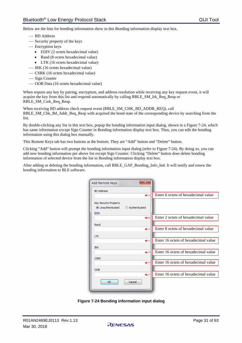
Below are the lists for bonding information show in this Bonding information display text box.
BD Address Security property of the keys Encryption keys
• EDIV (2 octets hexadecimal value) • Rand (8 octets hexadecimal value) • LTK (16 octets hexadecimal value)
IRK (16 octets hexadecimal value) CSRK (16 octets hexadecimal value) Sign Counter OOB Data (16 octets hexadecimal value)
When require any key by pairing, encryption, and address resolution while receiving any key request event, it will acquire the key from this list and respond automatically by calling RBLE_SM_Irk_Req_Resp or RBLE_SM_Csrk_Req_Resp.
When receiving BD address check request event (RBLE_SM_CHK_BD_ADDR_REQ), call RBLE_SM_Chk_Bd_Addr_Req_Resp with acquired the bond state of the corresponding device by searching from the list.
By double-clicking any list in this text box, popup the bonding information input dialog, shown in a Figure 7-24, which has same information except Sign Counter in Bonding information display text box. Thus, you can edit the bonding information using this dialog box manually.
This Remote Keys tab has two buttons at the bottom. They are “Add” button and “Delete” button.
Clicking “Add” button will prompt the bonding information input dialog (refer to Figure 7-24). By doing so, you can add new bonding information per above list except Sign Counter. Clicking “Delete” button does delete bonding information of selected device from the list in Bonding information display text box.
After adding or deleting the bonding information, call RBLE_GAP_Bonding_Info_Ind. It will notify and renew the bonding information to BLE software.
Figure 7-24 Bonding information input dialog
Enter 6 octets of hexadecimal value
Enter 2 octets of hexadecimal value
Enter 8 octets of hexadecimal value
Enter 16 octets of hexadecimal value
Enter 16 octets of hexadecimal value
Enter 16 octets of hexadecimal value
Enter 16 octets of hexadecimal value

Bluetooth® Low Energy Protocol Stack GUI Tool
R01AN2469EJ0113 Rev.1.13 Page 32 of 63 Mar 30, 2018
7.2.3 Vendor Specific Tab In the Vendor Specific tab, it has Renesas original extended features, such as Direct Test Mode using the rBLE API, writing BD address, and transmit power setting. You can test in Direct Test Mode using Direct Test Mode group box, can set Bluetooth Address and can set transmit power. When you switch to this tab first after starting the GUI tool, it calls RBLE_VS_Enable and does enable the Vendor Specific feature.
Table 7-12 List of API called by Vendor Specific tab
API Behavior RBLE_VS_Enable Enable VS feature RBLE_VS_Test_End Stop Rx or Tx test RBLE_VS_Set_Test_Parameter Set extended DTM parameters RBLE_VS_Test_Rx_Start Start Rx test RBLE_VS_Test _Tx_Start Start Tx test RBLE_VS_Read_Test_RSSI Get test RSSI value RBLE_VS_Flash_Management Execute Data Flash access management RBLE_VS_Write_Bd_Address Write BD address RBLE_VS_Adapt_Enable Enable or Disable adaptable feature RBLE_VS_Set_Tx_Power Set Tx power
Figure 7-25 Vendor Specific tab
• Direct Test Mode group box For direct testing, you can select Test End or Rx Test Mode or Tx Test Mode radio button in this Direct Test Mode group box. After selecting the mode, press the “Execute” button to stop Test Mode, or to start Rx Test Mode or to start Tx Test Mode. Upon pressing “Execute” button with Test End option calls RBLE_VS_Test_End, and ends the reception or the transmission test, which have being executed.

Bluetooth® Low Energy Protocol Stack GUI Tool
R01AN2469EJ0113 Rev.1.13 Page 33 of 63 Mar 30, 2018
Rx Test Mode group box allows configuring parameters such as Reception frequency and the extended Direct Test Mode features. Therefore, select one of the frequencies ranging from 2402MHz to 2480MHz using drop-down arrow to set Reception frequency. For the extended Direct Test Mode features, enter number of receive packets, at which to finish current reception test, in “rx_nb_packet” text box. Setting zero value in this text box will not end the test automatically. Checking the “Enable burst transfer” check box will be enabling the burst transfer. Upon pressing “Execute” button with Rx Test Mode option calls RBLE_VS_Set_Test_Parameter and RBLE_VS_Test_Rx_Start with specified parameters in Rx Test Mode group box, and start reception test.
You, finally, receive completion of the reception test event (RBLE_VS_EVENT_TEST_END_COMP), at the end of the test. Subsequently, display numbered of received packets in the "Received Packets" text box.
Tx Test Mode group box allows setting parameters such as Transmission frequency and the extended Direct Test Mode features. Select one of the frequencies same as Rx Test Mode group box for transmission frequency. Moreover, you can set Transmission packet payload length in “Packet_Length” and set Transmission packet payload type at “Packet_Data_Type”. For the extended Direct Test Mode features, enter number of transmit packets, at which to finish current transmission test, in “tx_nb_packet” text box. Setting zero value in this text box will not end automatically the test. In addition, you can set enabling or disabling burst transfer, or continuous carrier wave (CW) output at “infinit_setting” by using drop-down arrows. Upon pressing “Execute” button with Tx Test Mode option calls RBLE_VS_Set_Test_Parameter and RBLE_VS_Test_Tx_Start with specified parameters in Tx Test Mode group box, and start transmission test.
For RSSI value, you can read by pressing “Get RSSI” button. Pressing this button calls RBLE_VS_Read_Test_RSSI, and acquire RSSI value under reception Direct Test Mode. Alternately, manage regular RSSI reading by checking "Periodically" check box with interval value in “sec” text box, which allow setting in second range.
• Bluetooth Address group box By using this group box, you can write 6 octets hexadecimal value for the specified public address to store in nonvolatile memory (Data Flash). For writing this Bluetooth Address entered in the text box, press “Set” button. It executes RBLE_VS_Flash_Management and RBLE_VS_Write_Bd_Address. The Bluetooth Address will be reflected when the GAP reset processing (RBLE_GAP_Reset) is finished after Bluetooth device restart.
• Adaptable group box By using this group box, you can enable or disable Adaptable function. Select Disable or Enable using drop-down arrow and press “Set” button calls RBLE_VS_Adapt_Enable.
• Tx Power group box By using this group box, you can set the transmit power level. Specifying 0x0010 in “Handle” drop-down list sets transmit power level during the Advertising, Scanning, or Initiating procedure. You can also select one of nine power levels using “Power” drop-down list and one of four states using “State” drop-down list. Select “Handle”, “Power” and “State” using drop-down list then press “Set” button calls RBLE_VS_Set_Tx_Power. It will set transmit power with specified parameters.

Bluetooth® Low Energy Protocol Stack GUI Tool
R01AN2469EJ0113 Rev.1.13 Page 34 of 63 Mar 30, 2018
7.2.4 GATT Tab GATT tab has two sub tabs: Client and Server. The Client and Server tabs. They are shown in Figure 7-26 and Figure 7-31 respectively. When you switch to this tab first after starting the GUI tool, it calls RBLE_GATT_Enable and does enable the GATT feature.
Table 7-13 List of API called by GATT tab
API Behavior RBLE_GATT_Enable Enable GATT feature
(1) GATT – Client tab
In the GATT, Client tab has Result display text box and Command execution text box, which consist of four sub tabs: Service Discovery, Characteristic Discovery, Read and Write. Using these tabs, you can perform service or characteristic discovery as well as characteristic value read and write. Figure 7-26 shows the GATT, Client tab.
Table 7-14 List of API called by GATT - Client tab
API Behavior RBLE_GATT_Discovery_Service_Request Discover services RBLE_GATT_Discovery_Char_Request Discover characteristics RBLE_GATT_Discovery_Char_Descriptor_Request Discover characteristic descriptors RBLE_GATT_Read_Char_Request Read characteristic value RBLE_GATT_Write_Char_Request Write characteristic value
Figure 7-26 GATT – Client tab
Command execution text box
Result display text box

Bluetooth® Low Energy Protocol Stack GUI Tool
R01AN2469EJ0113 Rev.1.13 Page 35 of 63 Mar 30, 2018
• Command execution text box Here is the detail on Command execution text box for each tab.
Service Discovery tab Figure 7-27 shows the Service Discovery tab. You can choose Discovery Types such as Discover All Primary Services, Discover Primary Services by Service UUID and Find Included Services. Set one of the “UUID” radio buttons for its size 16 bit or 32 bit or 128 bit along with specific service from drop-down list or text box. If you find included service, enter Start Handle and End Handle. Finally, pressing “Discover” button calls RBLE_GATT_Discovery_Service_Request with specified parameters and executes discovery services on a remote server.
Figure 7-27 GATT Client – Service Discovery
Characteristic Discovery tab Figure 7-28 shows the Characteristic Discovery tab. Select one of the Discovery Types: Discover All Characteristics of a Service, Discover Characteristic by UUID and Discover All Characteristic Descriptors. Set one of the “UUID” radio buttons for its size 16 bit or 32 bit or 128 bit along with specific characteristics from drop-down list. If needed, enter value in Start Handle and End Handle. Finally, you can press “Discover” button to call RBLE_GATT_Discovery_Char_Request or RBLE_GATT_Discovery_Char_Descriptor_Request with specified parameters. It will carry out the discovery characteristics or characteristic descriptors on a remote server.
Figure 7-28 GATT Client – Characteristic Discovery

Bluetooth® Low Energy Protocol Stack GUI Tool
R01AN2469EJ0113 Rev.1.13 Page 36 of 63 Mar 30, 2018
Read tab Figure 7-29 shows the Read tab in GATT Client. This function reads either characteristic value or characteristic descriptor on the remote GATT server. Before reading, set one of the below Read Types. After that, define handle in “Handle” text box. • Read Characteristic Value • Read Using Characteristic UUID • Read Long Characteristic Values • Read Characteristic Descriptors • Read Long Characteristic Descriptors If you select either Read Long Characteristic Values or Read Long Characteristic Descriptor, you need to enter Offset value in decimal format. After setting above parameters, pressing “Read” button calls RBLE_GATT_Read_Char_Request with specified parameters, and executes read characteristic value from a remote server.
Figure 7-29 GATT Client – Read
Write tab Figure 7-30 shows the Write tab in GATT Client. Using this function, you can write either characteristic value or characteristic descriptor on the remote GATT server. Before writing, choose one of the below Write Types and enter handle value in “Handle” text box. • Write Without Response • Signed Write Without Response • Write Characteristic Value • Write Long Characteristic Values • Write Characteristic Descriptors • Write Long Characteristic Descriptors If you select either Write Long Characteristic Values or Write Long Characteristic Descriptors, you need to enter Offset value in decimal format. Select either Hex or ASCII format to write in Write Data text box then enter the data. Now, pressing “Write” button calls RBLE_GATT_Write_Char_Request with specified parameters and executes write characteristic value to a remote server.
Figure 7-30 GATT Client – Write
• Result display text box The Client tab also has Remote GATT Database table, which shows the results inside Result display text box. In the list, show the information obtained by execution of the commands from above listed tabs.

Bluetooth® Low Energy Protocol Stack GUI Tool
R01AN2469EJ0113 Rev.1.13 Page 37 of 63 Mar 30, 2018
Select one of the listed database component and double clicking to selected component will automatically fill up the respective handle value into “Handle”, “Start Handle” or “End Handle” text boxes in Command execution text box. If you need to set the value, you can simply access the respective text box and enter the value.

Bluetooth® Low Energy Protocol Stack GUI Tool
R01AN2469EJ0113 Rev.1.13 Page 38 of 63 Mar 30, 2018
(2) GATT – Server tab
In the GATT tab, Server tab, shown in Figure 7-31, has Server Initiated group box and Permission Settings group box. This tab does indication or notification, and local GATT database update.
Table 7-15 List of API called by GATT - Server tab
API Behavior RBLE_GATT_Set_Data Update characteristic value RBLE_GATT_Indicate_Request Execute indication RBLE_GATT_Notify_Request Execute notification RBLE_GATT_Set_Permission Set permission RBLE_GATT_Write_Response Respond characteristic value write request
Figure 7-31 GATT – Server tab
• Server Initiated group box Using this group box, you can update the data in the local GATT database with specifying handle. Key in handle of hexadecimal value in “Handle” text box and select either Hex or ASCII format to write Data text box then enter the data. There are three buttons in this group box. If you want to indicate or notify characteristic value from the local GATT server to the remote GATT client, press one of the respective buttons. Pressing Set Data button only update characteristic value in the local GATT server relating to specified handle.
Pressing “Indicate” button calls RBLE_GATT_Set_Data, and update the attribute value of the specified handle. Successively, call RBLE_GATT_Indicate_Request, and do characteristic value indications.
Pressing “Notify” button calls RBLE_GATT_Set_Data, and update the attribute value of the specified handle. Successively, call RBLE_GATT_Notify_Request, and do characteristic value notifications.
Pressing “Set Data” button calls RBLE_GATT_Set_Data, and update the attribute value of the specified handle.

Bluetooth® Low Energy Protocol Stack GUI Tool
R01AN2469EJ0113 Rev.1.13 Page 39 of 63 Mar 30, 2018
• Permission Settings group box The group box allows you to set the permission to the specified range of local GATT database by handles. Before pressing “Set Permission” button, check one or more check boxes in this group box, and key in Start and End handle value to set handles in series. After that, pressing “Set Permission” button calls RBLE_GATT_Set_Permission, and executes permission settings of the specified handle range attributes.
When receive the characteristic value write indication event (RBLE_GATT_EVENT_WRITE_CMD_IND) from the remote GATT Client, it will call RBLE_GATT_Set_Data, and update the attribute value of the specified handle.
In the case of written by the “Write Request”, dialog box is shown in Figure 7-32. Respond by pressing the “Accept” button or “Reject” button. By pressing either button, RBLE_GATT_Write_Response is called.
Figure 7-32 Write Indication by “Write Request”

Bluetooth® Low Energy Protocol Stack GUI Tool
R01AN2469EJ0113 Rev.1.13 Page 40 of 63 Mar 30, 2018
7.2.5 Profiles Tab There are five profiles in Profiles tabs: They are Find Me, Proximity, Alert Notification, Heart Rate, and Time. Each has its own tab to configure the setting.
(1) Profiles – Find Me tab
The Find Me tab performs Find Me Locator role and Target role functions. Thus, this tab has two group boxes: Locator and Target. Set Find Me Locator as GATT Client and Find Me Target as GATT server. Figure 7-33 shows Find Me tab.
Table 7-16 List of API called by Profiles – Find Me tab
API Behavior RBLE_FMP_Locator_Enable Enable Locator role RBLE_FMP_Locator_Disable Disable Locator role RBLE_FMP_Locator_Set_Alert Set alert level value RBLE_FMP_Target_Enable Enable Target role RBLE_FMP_Target_Disable Disable Target role
Figure 7-33 Profiles – Find Me tab
• Locator group box In the Locator group box, it has three buttons: “Enable”, “Disable” and “Set Alert Level”,
To enable the locator, press “Enable” button. It calls RBLE_FMP_Locator_Enable with specified parameters, and does enable the Find Me Locator role. This will display the acquired service information in the Remote GATT Database at GATT-Client tab. If you select "Normal" radio button, the handle information, which acquired in the previous connection, will be used.
Pressing “Disable” button calls RBLE_FMP_Locator_Disable, and disable the Find Me Locator role.

Bluetooth® Low Energy Protocol Stack GUI Tool
R01AN2469EJ0113 Rev.1.13 Page 41 of 63 Mar 30, 2018
To set alert level, select one of the alert level radio buttons, which are No Alert, Mild Alert and High Alert. Then press “Set Alert Level” button. It calls RBLE_FMP_Locator_Set_Alert, and write specified Alert Level characteristic value to the Target device.
• Target group box The Target group box has “Enable” and “Disable” buttons. To show alert level by notification, there is an Alert Level text box. You can set security option by checking one of the check boxes such as No security, Unauthenticated Paring, Authenticated Paring, Authorization and Encryption. Pressing “Enable” button in Target group box calls RBLE_FMP_Target_Enable with specified security level and does enable the Find Me Target role.
Pressing “Disable” button in Target group box calls RBLE_FMP_Target_Disable, and disable the Find Me Target role.
Figure 7-34 shows Alert Level display text box. In this text box, the Alert Level message has been notified by alert indication event (RBLE_FMP_EVENT_TARGET_ALERT_IND). The text box color will change when the alert level change.
Figure 7-34 Display text box of Alert Level

Bluetooth® Low Energy Protocol Stack GUI Tool
R01AN2469EJ0113 Rev.1.13 Page 42 of 63 Mar 30, 2018
(2) Profiles – Proximity tab
Figure 7-35 shows Proximity tab, which performs Proximity Monitor role and Reporter role and it has two group boxes: Monitor and Reporter. The Proximity Monitor shall act as GATT Client, and the Proximity Reporter shall act as GATT server. Enabling this profile will be monitoring the proximity between two connected Bluetooth devices.
Table 7-17 List of API called by Profiles – Proximity tab
API Behavior RBLE_PXP_Monitor_Enable Enable Monitor role RBLE_PXP_Monitor_Disable Disable Monitor role RBLE_PXP_Monitor_Set_Alert_Level Set alert level value RBLE_PXP_Monitor_Get_Tx_Power Get Tx power RBLE_PXP_Monitor_Get_Alert_Level Get alert level value RBLE_GAP_Read_RSSI Get RSSI value RBLE_PXP_Reporter_Enable Enable Reporter role RBLE_PXP_Reporter_Disable Disable Reporter role
Figure 7-35 Profiles – Proximity tab
• Monitor group box In the Monitor group box, it has five buttons: “Enable”, “Disable”, “Set Alert Level”, “Get Tx Power” and “Get Alert Level”. Before enabling Proximity Monitor, select “Discovery” or “Normal” radio button. Selecting “Normal” will use the handle information acquired in the previous connection.
Pressing “Enable” button in this group calls RBLE_PXP_Monitor_Enable with specified parameters, and enable the Proximity Monitor role. At GATT-Client tab, the acquired service information is listed in the Remote GATT Database.
Pressing “Disable” button calls RBLE_PXP_Monitor_Disable, and disable the Proximity Monitor role.
To set alert level, select either Link Loss Alert or Immediate Alert option from drop-down list, then choose one of the alert level radio buttons: No Alert, Mild Alert and High Alert. After that, pressing “Set Alert Level” button calls

Bluetooth® Low Energy Protocol Stack GUI Tool
R01AN2469EJ0113 Rev.1.13 Page 43 of 63 Mar 30, 2018
RBLE_PXP_Monitor_Set_Alert_Level. The Reporter device will be set the specified alert level value to Alert Level characteristic of Link Loss Service or Immediate Alert Service per respective option.
Pressing “Get Tx Power” button calls RBLE_PXP_Monitor_Get_Tx_Power, and reads the Tx Power Level characteristic value exposed by the Reporter device. The Tx Power level value will be shown with dBm unit in the text box when receive the characteristic read response event (RBLE_PXP_EVENT_MONITOR_READ_CHAR_RESPONSE).
Again, pressing “Get Alert Level” button calls RBLE_PXP_Monitor_Get_Alert_Level, and reads the Alert Level characteristic value in Link Loss service exposed by the Reporter device. Subsequently receiving characteristic read response event (RBLE_PXP_EVENT_MONITOR_READ_CHAR_RESPONSE) displays the Alert level.
Using Calculate Path Loss, you can monitor the path loss level display with progressive bar, which has three path lost ranges: normal range (index below 60), warning range (index below 80), and alarm range (index above 80). The index value will be calculated by subtracting the RSSI from Tx Power Level. Figure 7-36 shows path loss progressive bar with three range of path loss levels.
When check “Calculate Path Loss” check box, RSSI value will be acquired periodically with the specified interval in seconds. This will keep calling RBLE_GAP_Read_RSSI and update the path loss progressive bar.
Figure 7-36 Display part of path loss
• Reporter group box The Reporter group box has “Enable” and “Disable” buttons. It has also an Alert Level text box for showing alert level by notification.
Pressing “Enable” button in this group calls RBLE_PXP_Reporter_Enable with specified parameters, and enable the Proximity Reporter role.
Pressing “Disable” button calls RBLE_PXP_Reporter_Disable, and disable the Proximity Reporter role.
The Alert Level display text box will show Alert Level, which has been notified by alert indication event (RBLE_PXP_EVENT_REPORTER_ALERT_IND). The text box color will be changed with respect to the alert level. Refer to below Figure 7-37
Figure 7-37 Display text box of Alert Level

Bluetooth® Low Energy Protocol Stack GUI Tool
R01AN2469EJ0113 Rev.1.13 Page 44 of 63 Mar 30, 2018
(3) Profiles – Alert Notification tab
Figure 7-38 shows Alert Notification Profile, which Client device receives different types of alerts and event information from the server device. Using Alert Notification tab, you can configure Alert Notification Client role or Server role.
Table 7-18 List of API called by Profiles – Alert Notification tab
API Behavior RBLE_ANP_Client_Enable Enable Client role RBLE_ANP_Client_Disable Disable Client role RBLE_ANP_Client_Read_Char Read characteristic value RBLE_ANP_Client_Write_Char Control notification RBLE_ANP_Client_Write_Alert_Notification_CP Set control point RBLE_ANP_Server_Enable Enable Server role RBLE_ANP_Server_Disable Disable Server role RBLE_ANP_Server_Send_New_Alert Send new alert information RBLE_ANP_Server_Send_Unread_Alert Send unread alert information
Figure 7-38 Profiles – Alert Notification tab
• Client group box In the Client group box, there are five buttons: “Enable”, “Disable”, “Read Char”, “Write Char” and “Write CP”. Before enabling Alert Notification Client, select “Discovery” or “Normal” radio button. Selecting “Normal” will use the handle information acquired in the previous connection.
Pressing “Enable” button in this group calls RBLE_ANP_Client_Enable with specified parameters, and enable the Alert Notification Client role. At GATT-Client tab, the acquired service information is listed in the Remote GATT Database.
Pressing “Disable” button calls RBLE_ANP_Client_Disable, and disables the Alert Notification Client role.

Bluetooth® Low Energy Protocol Stack GUI Tool
R01AN2469EJ0113 Rev.1.13 Page 45 of 63 Mar 30, 2018
For reading characteristic value or characteristic descriptor, select one of the options from drop-down list.
1. Supported New Alert Category 2. New Alert Client Characteristic Configuration 3. Supported Unread Alert Category 4. Unread Alert Status Client Characteristic Configuration
Pressing “Read Char” button calls RBLE_ANP_Client_Read_Char with specified parameters, and read a characteristic value or characteristic descriptor exposed by Server device. Display the characteristic value or characteristic descriptor upon receiving characteristic read response event (RBLE_ANP_EVENT_CLIENT_READ_CHAR_RESPONSE).
For writing characteristic descriptor, set either “New” or “Unread” radio button, then select Disable Notification or Enable Notification.
Pressing “Write Char” button calls RBLE_ANP_Client_Write_Char, and writes specified value to selected Client Characteristic Configuration Descriptor of the alert notification service to the Server.
Set one command option and one Category for drop-down lists. After that, pressing “Write CP” button calls RBLE_ANP_Client_Write_Alert_Notification_CP with specified parameters, and sets the Alert Notification Control Point.
You will get message box prompt as shown in Figure 7-39 to display the content of the notification when receive New Alert notification event (RBLE_ANP_EVENT_CLIENT_NEW_ALERT_NTF) or Unread Alert Status event (RBLE_ANP_EVENT_CLIENT_UNREAD_ALERT_NTF) from the Server.
Figure 7-39 New Alert / Unread Alert Status Notification
• Server group box In the Server group box, you can use “Enable” button, “Disable” button, and two sub group boxes such as New Alert and Unread Alert Status for interaction with Client.
Before enabling Alert Notification Server, select “Configuration” or “Normal” radio button. Selecting “Normal” will use the handle information acquired in the previous connection.
Pressing “Enable” button in this group calls RBLE_ANP_Server_Enable with specified security level, and enables the Alert Notification Server role.
Pressing “Disable” button calls RBLE_ANP_Server_Disable, and disables the Alert Notification Server role.
When Client device enables Notification either New or Unread, the respective “Notify” buttons will be available. Otherwise, the “Notify” buttons will be grayed out. Once “Notify” button active, you can send New Alert or Unread Alert Status to Client.
Pressing “Notify” button in New Alert group box calls RBLE_ANP_Server_Send_New_Alert with specified parameters, and notifies New Alert information to the Client.

Bluetooth® Low Energy Protocol Stack GUI Tool
R01AN2469EJ0113 Rev.1.13 Page 46 of 63 Mar 30, 2018
Pressing “Notify” button in Unread Alert Status group box calls RBLE_ANP_Server_Send_Unread_Alert with specified parameters, and notifies Unread Alert Status information to the Client.
The Write Control Point Received dialog box, shown in Figure 7-40, will be prompt when receive Alert Notification Control Point change indication event (RBLE_ANP_EVENT_SERVER_CHG_ALERT_NTF_CP_IND). Execute the operation according to the displayed Command and Category in the message box.
Figure 7-40 Alert Notification Control Point change indication

Bluetooth® Low Energy Protocol Stack GUI Tool
R01AN2469EJ0113 Rev.1.13 Page 47 of 63 Mar 30, 2018
(4) Profiles – Heart Rate tab
Figure 7-41 shows Heart Rate profile, which interact between a Heart Rate Collector device and a Heart Rate Sensor device. The Collector shall act as GATT Client, and Heart Rate Sensor shall act as GATT Server. You can use this Heart Rate tab to perform Heart Rate Collector role and Sensor role functions.
Table 7-19 List of API called by Profiles – Heart Rate tab
API Behavior RBLE_HRP_Collector_Enable Enable Collector role RBLE_HRP_Collector_Disable Disable Collector role RBLE_HRP_Collector_Read_Char Read characteristic value RBLE_HRP_Collector_Write_Char Control notification RBLE_HRP_Collector_Write_Control_Point Set control point RBLE_HRP_Sensor_Enable Enable Sensor role RBLE_HRP_Sensor_Disable Disable Sensor role RBLE_HRP_Sensor_Send_Measurements Send heart rate measurements
Figure 7-41 Profiles – Heart Rate tab
• Collector group box The Collector group box has five buttons: “Enable”, “Disable”, “Read Char”, “Write Char” and “Reset Energy Expended”.
To enable the Collector, press “Enable” button. It calls RBLE_HRP_Collector_Enable with specified parameters, and does enable the Heart Rate Collector role. This will display the acquired service information in the Remote GATT Database at GATT-Client tab. The handle information, acquired in the previous connection, will be used if you select “Normal” radio button.
Pressing “Disable” button calls RBLE_HRP_Collector_Disable, and disable the Heart Rate Collector role.

Bluetooth® Low Energy Protocol Stack GUI Tool
R01AN2469EJ0113 Rev.1.13 Page 48 of 63 Mar 30, 2018
For reading characteristic value or characteristic descriptor, select one of the options from drop-down list and press “Read Char” button. It will call RBLE_HRP_Collector_Read_Char with specified parameters, and read a characteristic value or characteristic descriptor exposed from the Sensor device. Subsequently display the characteristic value or characteristic descriptor in the text box upon receiving characteristic read response event (RBLE_HRP_EVENT_COLLECTOR_READ_CHAR_RESPONSE).
For writing characteristic descriptor, select Disable Notification or Enable Notification and press “Write Char” button. It will call RBLE_HRP_Collector_Write_Char, and write specified value to Client Characteristic Configuration Descriptor of the Sensor to control Heart Rate Measurement notification from the Sensor.
Pressing “Reset Energy Expended” button sets the Heart Rate Control Point characteristic value of the heart rate service. This button press calls RBLE_HRP_Collector_Write_Control_Point.
When receive Heart rate measurement information notification event (RBLE_HRP_EVENT_COLLECTOR_MEASUREMENTS_NTF), the content of the notification which displayed in the message box. Figure 7-42 shows the message box.
Figure 7-42 Heart Rate Measurement Notification
• Sensor group box In the Sensor group box, use “Enable” button or “Disable” button for enabling or disabling the Heart Rate Sensor respectively.
Pressing “Enable” button in Sensor group box calls RBLE_HRP_Sensor_Enable with specified security level, and enable the Heart Rate Sensor role. Client Characteristic Configuration Descriptor value, set from the Collector in the previous connection, will be used if you select “Normal” radio button.
Pressing “Disable” button calls RBLE_HRP_Sensor_Disable, and disable the Heart Rate Sensor role.
When Collector enables Notification, “Send Measurement” button will be available. Otherwise, it will be grayed out. Before sending measurement, check appropriate check boxes and key in the values to send to Collector.
Pressing “Send Measurements” button calls RBLE_HRP_Sensor_Send_Measurements with specified parameters, and notify Heart Rate Measurement information to the Collector.
Figure 7-43 shows dialog box for Heart Rate Control Point change. When receive Heart Rate Control Point change indication event (RBLE_HRP_EVENT_SENSOR_CHG_CP_IND), after clicking “OK” button sets to 0 in the Energy Expended text box from Sensor group box.

Bluetooth® Low Energy Protocol Stack GUI Tool
R01AN2469EJ0113 Rev.1.13 Page 49 of 63 Mar 30, 2018
Figure 7-43 Heart Rate Control Point change indication

Bluetooth® Low Energy Protocol Stack GUI Tool
R01AN2469EJ0113 Rev.1.13 Page 50 of 63 Mar 30, 2018
(5) Profiles – Time tab
Figure 7-44 shows Time Profile, which allows the Time Client to receive date, time, time zone, and daylight savings time (DST) information exposed by the Time Server. In the Time tab, you can configure Time Client role and Server role functions.
Table 7-20 List of API called by Profiles – Time tab
API Behavior RBLE_TIP_Client_Enable Enable Client role RBLE_TIP_Client_Disable Disable Client role RBLE_TIP_Client_Read_Char Read characteristic value RBLE_TIP_Client_Write_Char Control notification RBLE_TIP_Client_Write_Time_Update_CP Set control point RBLE_TIP_Server_Enable Enable Server role RBLE_TIP_Server_Disable Disable Server role RBLE_TIP_Server_Write_Data Update characteristic value RBLE_TIP_Server_Send_Current_Time Send current time information
Figure 7-44 Profiles – Time tab
• Client group box In the Client group box, there are five buttons: “Enable”, “Disable”, “Read Char”, “Write Char” and “Write CP”. Before enabling, select “Discovery” or “Normal” radio button. Selecting “Normal” will use the handle information acquired in the previous connection.
Pressing “Enable” button in this group box calls RBLE_TIP_Client_Enable with specified parameters, and enable the Time Client role. At GATT-Client tab, the acquired service information is listed in the Remote GATT Database.
Pressing “Disable” button calls RBLE_TIP_Client_Disable, and disable the Time Client role.

Bluetooth® Low Energy Protocol Stack GUI Tool
R01AN2469EJ0113 Rev.1.13 Page 51 of 63 Mar 30, 2018
Before reading characteristic value or characteristic descriptor, select one of the below options from drop-down list.
1. Current Time 2. Current Time Characteristic Configuration 3. Local Time Information 4. Reference Time Information 5. Time with DST 6. Time Update State
Pressing “Read Char” button calls RBLE_TIP_Client_Read_Char with specified parameters, and read a characteristic value or characteristic descriptor exposed by the Server device. Display the characteristic value or characteristic descriptor upon receiving characteristic read response event (RBLE_TIP_EVENT_CLIENT_READ_CHAR_RESPONSE).
For writing characteristic descriptor, select Disable Notification or Enable Notification from drop-down list.
Pressing “Write Char” button calls RBLE_TIP_Client_Write_Char, and write specified value to Client Characteristic Configuration Descriptor of the Server to control Current Time notification from the Server.
Select Get Reference Update or Cancel Reference Update from drop-down list. Pressing “Write CP” button calls RBLE_TIP_Client_Write_Time_Update_CP, and set the Time Update Control Point.
You will get message box prompt as shown in Figure 7-45 to display the content of the notification when receive Current time notification event (RBLE_TIP_EVENT_CLIENT_CURRENT_TIME_NTF) from the Server.
Figure 7-45 Current Time Notification
• Server group box In the Server group box, there are “Enable” button and “Disable” button for enabling or disabling Time Service.
Pressing “Enable” button in this group calls RBLE_TIP_Server_Enable with specified security level, and enable the Time Server role. Select “Configuration” or “Normal” radio button. Selecting "Normal" will use Client Characteristic Configuration Descriptor value set from the Client in the previous connection.
Pressing “Disable” button calls RBLE_TIP_Server_Disable, and disable the Time Server role.
There are five tabs in this server group box for Time Service configuration.
1. Current Time 2. Local Time 3. Reference Time 4. Next DST 5. Update State
You can set Characteristic value from the above listed tabs and details are as follow.
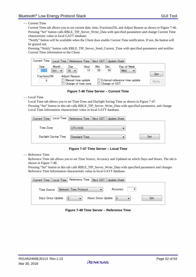
Bluetooth® Low Energy Protocol Stack GUI Tool
R01AN2469EJ0113 Rev.1.13 Page 52 of 63 Mar 30, 2018
Current Time Current Time tab allows you to set current date, time, Fractions256, and Adjust Reason as shown in Figure 7-46. Pressing “Set” button calls RBLE_TIP_Server_Write_Data with specified parameters and change Current Time characteristic value in local GATT database. “Notify” button will be available when the Client does enable Current Time notification. If not, the button will be grayed out. Pressing “Notify” button calls RBLE_TIP_Server_Send_Current_Time with specified parameters and notifies Current Time information to the Client.
Figure 7-46 Time Server – Current Time
Local Time Local Time tab allows you to set Time Zone and Daylight Saving Time as shown in Figure 7-47. Pressing “Set” button in this tab calls RBLE_TIP_Server_Write_Data with specified parameters, and change Local Time Information characteristic value in local GATT database.
Figure 7-47 Time Server – Local Time
Reference Time Reference Time tab allows you to set Time Source, Accuracy and Updated on which Days and Hours. The tab is shown in Figure 7-48. Pressing “Set” button in this tab calls RBLE_TIP_Server_Write_Data with specified parameters and changes Reference Time Information characteristic value in local GATT database.
Figure 7-48 Time Server – Reference Time

Bluetooth® Low Energy Protocol Stack GUI Tool
R01AN2469EJ0113 Rev.1.13 Page 53 of 63 Mar 30, 2018
Next DST Next DST tab allows you to set daylight saving time: date and time, and select option from drop-down list shown in Figure 7-49. Pressing “Set” button in this tab calls RBLE_TIP_Server_Write_Data with specified parameters and changes Time with DST characteristic value in local GATT database.
Figure 7-49 Time Server – Next DST
Update State Update State tab allows you to set Current State and Result as shown in Figure 7-50. Pressing “Set” button in this tab calls RBLE_TIP_Server_Write_Data with specified parameters and changes Time Update State characteristic value in local GATT database.
Figure 7-50 Time Server – Update State
You will get dialog box prompt as shown in Figure 7-51 when receive Time Update Control Point change indication event (RBLE_TIP_EVENT_SERVER_CHG_TIME_UPDATE_CP_IND). Press “OK” button to appropriate request, in which shows message with Get Reference Update or Cancel Reference Update, from the Client.
Figure 7-51 Time Update Control Point change indication

Bluetooth® Low Energy Protocol Stack GUI Tool
R01AN2469EJ0113 Rev.1.13 Page 54 of 63 Mar 30, 2018
8. Appendix 8.1 File and Folder Organization The file and folder organization related to the GUI Tool is as shown below.
an_r01an2469ej0XXX_g1dguitool ├ r01an2469ej0XXX_g1dguitool.pdf Application Note: GUI Tool └ rBLE_Tool Executable files ├ rBLE_Tool.exe GUI Tool executable program for windows PC ├ rBLE_Tool.ini INI file for GUI Tool └ rBLE_Tool_Err_Msg.tbl Definition file for error message
8.2 Error Messages GUI Tool displays the error message box shown in Figure 8-1 when occur an error. In this message box, display Error ID, error message, and the source file name and source code line that detected the error.
Figure 8-1 Error Message Box
The error IDs, and the error messages are listed in below table.
Error ID Error Message Supplement, countermeasure 10000 INTERNAL ERROR: Serial
communication program cannot be started. Please restart rBLE_Tool.
Restart GUI Tool.
10001 Cannot open serial port (port number). Confirm the serial port state.
Check the status of serial port.

Bluetooth® Low Energy Protocol Stack GUI Tool
R01AN2469EJ0113 Rev.1.13 Page 55 of 63 Mar 30, 2018
8.3 API Quick Reference List
Table 8-1 API Quick Reference List
API Behavior Tab GAP RBLE_GAP_Reset Execute GAP reset GAP - Generic
RBLE_GAP_Set_Name Set local device name GAP - Generic
RBLE_GAP_Observation_Enable Enable observation GAP - Scanning
Execute connection procedure GAP - White List
RBLE_GAP_Observation_Disable Disable observation GAP - Scanning
RBLE_GAP_Broadcast_Enable Enable broadcast GAP - Advertising
RBLE_GAP_Broadcast_Disable Disable broadcast GAP - Advertising
RBLE_GAP_Set_Bonding_Mode Set bonding mode GAP - Security
RBLE_GAP_Set_Security_Request Set security mode GAP - Security
RBLE_GAP_Get_Device_Info Get local device information GAP - Generic
RBLE_GAP_Get_White_List_Size Get White List size GAP - White List
RBLE_GAP_Add_To_White_List Add address to White List GAP - White List
RBLE_GAP_Del_From_White_List Delete address from White List GAP - White List
RBLE_GAP_Get_Remote_Device_Name Get remote device name Peer Device - Information
RBLE_GAP_Get_Remote_Device_Info Get remote device information Peer Device - Information
RBLE_GAP_Device_Search Search remote device GAP - Scanning
RBLE_GAP_Set_Random_Address Set random address GAP - Generic
RBLE_GAP_Set_Privacy_Feature Set privacy feature GAP - Security
RBLE_GAP_Create_Connection Start LE link connection Peer Device - Connection
RBLE_GAP_Connection_Cancel Cancel LE link connection Peer Device - Connection
RBLE_GAP_Disconnect Disconnect LE link Peer Device - Connection
RBLE_GAP_Start_Bonding Start bonding Peer Device - Pair / Key Exchange
RBLE_GAP_Bonding_Info_Ind Indicate bonding information Peer Device - Remote Keys
RBLE_GAP_Bonding_Response Respond to bonding request Peer Device - Pair / Key Exchange
RBLE_GAP_Change_Connection_Param Change link parameters Peer Device - Connection
RBLE_GAP_Channel_Map_Req Set or Get channel map Peer Device - Information
RBLE_GAP_Read_RSSI Get RSSI value Peer Device - Information
Profiles - Proximity
SM RBLE_SM_Set_Key Set IRK or CSRK GAP - Security
RBLE_SM_Start_Enc Start encryption Peer Device - Pair / Key Exchange
RBLE_SM_Tk_Req_Resp Respond to TK request Peer Device - Pair / Key Exchange
RBLE_SM_Ltk_Req_Resp Respond to LTK request Peer Device - Pair / Key Exchange
RBLE_SM_Irk_Req_Resp Respond to IRK request Peer Device - Remote Keys
RBLE_SM_Csrk_Req_Resp Respond to CSRK request Peer Device - Remote Keys
RBLE_SM_Chk_Bd_Addr_Req_Resp Respond to BD address check request Peer Device - Remote Keys
VS RBLE_VS_Enable Enable VS feature Vendor Specific
RBLE_VS_Test_Rx_Start Start Rx test Vendor Specific
RBLE_VS_Test_Tx_Start Start Tx test Vendor Specific
RBLE_VS_Test_End Stop Rx or Tx test Vendor Specific
RBLE_VS_Set_Test_Parameter Set extended DTM parameters Vendor Specific
RBLE_VS_Read_Test_RSSI Get test RSSI value Vendor Specific
RBLE_VS_Write_Bd_Address Write BD address Vendor Specific

Bluetooth® Low Energy Protocol Stack GUI Tool
R01AN2469EJ0113 Rev.1.13 Page 56 of 63 Mar 30, 2018
RBLE_VS_Set_Tx_Power Set Tx power Vendor Specific
RBLE_VS_Flash_Management Execute Data Flash access management Vendor Specific
RBLE_VS_Adapt_Enable Enable or Disable adaptable feature Vendor Specific
GATT RBLE_GATT_Enable Enable GATT feature GATT
RBLE_GATT_Discovery_Service_Request Discover services GATT - Client
RBLE_GATT_Discovery_Char_Request Discover characteristics GATT - Client
RBLE_GATT_Discovery_Char_Descriptor_Request Discover characteristic descriptors GATT - Client
RBLE_GATT_Read_Char_Request Read characteristic value GATT - Client
RBLE_GATT_Write_Char_Request Write characteristic value GATT - Client
RBLE_GATT_Notify_Request Execute notification GATT - Server
RBLE_GATT_Indicate_Request Execute indication GATT - Server
RBLE_GATT_Write_Response Respond characteristic value write request GATT - Server
RBLE_GATT_Set_Permission Set permission GATT - Server
RBLE_GATT_Set_Data Update characteristic value GATT - Server
FMP RBLE_FMP_Locator_Enable Enable Locator role Profiles - Find Me
RBLE_FMP_Locator_Disable Disable Locator role Profiles - Find Me
RBLE_FMP_Locator_Set_Alert Set alert level value Profiles - Find Me
RBLE_FMP_Target_Enable Enable Target role Profiles - Find Me
RBLE_FMP_Target_Disable Disable Target role Profiles - Find Me
PXP RBLE_PXP_Monitor_Enable Enable Monitor role Profiles - Proximity
RBLE_PXP_Monitor_Disable Disable Monitor role Profiles - Proximity
RBLE_PXP_Monitor_Get_Alert_Level Get alert level value Profiles - Proximity
RBLE_PXP_Monitor_Set_Alert_Level Set alert level value Profiles - Proximity
RBLE_PXP_Monitor_Get_Tx_Power Get Tx power Profiles - Proximity
RBLE_PXP_Reporter_Enable Enable Reporter role Profiles - Proximity
RBLE_PXP_Reporter_Disable Disable Reporter role Profiles - Proximity
ANP RBLE_ANP_Client_Enable Enable Client role Profiles - Alert Notification
RBLE_ANP_Client_Disable Disable Client role Profiles - Alert Notification
RBLE_ANP_Client_Read_Char Read characteristic value Profiles - Alert Notification
RBLE_ANP_Client_Write_Alert_Notification_CP Set control point Profiles - Alert Notification
RBLE_ANP_Client_Write_Char Control notification Profiles - Alert Notification
RBLE_ANP_Server_Enable Enable Server role Profiles - Alert Notification
RBLE_ANP_Server_Disable Disable Server role Profiles - Alert Notification
RBLE_ANP_Server_Send_New_Alert Send new alert information Profiles - Alert Notification
RBLE_ANP_Server_Send_Unread_Alert Send unread alert information Profiles - Alert Notification
HRP RBLE_HRP_Collector_Enable Enable Collector role Profiles - Heart Rate
RBLE_HRP_Collector_Disable Disable Collector role Profiles - Heart Rate
RBLE_HRP_Collector_Read_Char Read characteristic value Profiles - Heart Rate
RBLE_HRP_Collector_Write_Char Control notification Profiles - Heart Rate
RBLE_HRP_Collector_Write_Control_Point Set control point Profiles - Heart Rate
RBLE_HRP_Sensor_Enable Enable Sensor role Profiles - Heart Rate
RBLE_HRP_Sensor_Disable Disable Sensor role Profiles - Heart Rate
RBLE_HRP_Sensor_Send_Measurements Send heart rate measurements Profiles - Heart Rate
TIP

Bluetooth® Low Energy Protocol Stack GUI Tool
R01AN2469EJ0113 Rev.1.13 Page 57 of 63 Mar 30, 2018
RBLE_TIP_Client_Enable Enable Client role Profiles - Time
RBLE_TIP_Client_Disable Disable Client role Profiles - Time
RBLE_TIP_Client_Read_Char Read characteristic value Profiles - Time
RBLE_TIP_Client_Write_Char Control notification Profiles - Time
RBLE_TIP_Client_Write_Time_Update_CP Set control point Profiles - Time
RBLE_TIP_Server_Enable Enable Server role Profiles - Time
RBLE_TIP_Server_Disable Disable Server role Profiles - Time
RBLE_TIP_Server_Send_Current_Time Send current time information Profiles - Time
RBLE_TIP_Server_Write_Data Update characteristic value Profiles - Time

Bluetooth® Low Energy Protocol Stack GUI Tool
R01AN2469EJ0113 Rev.1.13 Page 58 of 63 Mar 30, 2018
8.4 How to use the Direct Test Mode Direct Test Mode is executed in Vendor Specific tab. Refer to 7.2.3 about detail of Vendor Specific tab.
8.4.1 Direct Test Mode (Receiver)
Figure 8-2 Control of Direct Test Mode (Receiver)
You can start the Direct Test Mode (Receiver) by Rx Test Mode group box.
Set the reception frequency that is the same frequency as the transmitter by "Rx_Freq" after selecting Rx Test Mode radio button. After that, pressing “Execute” button starts receiving test packets.
To stop the Direct Test Mode (Receiver), press “Execute” button again after selecting Test End radio button. When the test is finished, you can check the number of reception packets in the Received Packets text box.
Test start / stop
Select for test stop
Select for test start
Set the test parameters
Display the number of receiving packets

Bluetooth® Low Energy Protocol Stack GUI Tool
R01AN2469EJ0113 Rev.1.13 Page 59 of 63 Mar 30, 2018
8.4.2 Direct Test Mode (Transmitter)
Figure 8-3 Control of Direct Test Mode (Transmitter)
You can start the Direct Test Mode (Transmitter) by Tx Test Mode group box.
Set the transmission frequency that is the same frequency as the receiver by "Tx_Freq" after selecting Tx Test Mode radio button. In Accordance with the test specification, also set the packet length in “Packet_Length” and set the data type in “Packet_Data_Type”. After that, pressing “Execute” button starts transmitting test packets.
To stop the Direct Test Mode (Transmitter), press “Execute” button again after selecting Test End radio button.
8.5 References 1. Visual C++ Redistributable for Visual Studio 2012 Update 4
http://www.microsoft.com/en-us/download/details.aspx?id=30679 2. FTDI (Future Technology Devices International) – Drivers
http://www.ftdichip.com/Drivers/D2XX.htm 3. Bluetooth Core Specification version 4.2
https://www.bluetooth.com/specifications/bluetooth-core-specification/legacy-specifications 4. GATT Specifications
https://www.bluetooth.com/specifications/gatt
Test start / stop
Select for test stop
Select for test start
Set the test parameters Set the test parameters Set the test parameters

Bluetooth® Low Energy Protocol Stack GUI Tool
R01AN2469EJ0113 Rev.1.13 Page 60 of 63 Mar 30, 2018
8.6 Terminology Term Description
Service A service is provided from a GATT server to a GATT client. The GATT server exposes some characteristics as the interface. The service prescribes how to access the exposed characteristics.
Profile A profile enables implementation of a use case by using one or more services. The services used are defined in the specifications of each profile.
Characteristic A characteristic is a value used to identify services. The characteristics to be exposed and their formats are defined by each service.
Role Each device takes the role prescribed by the profile or service in order to implement the specified use case.
Client Characteristic Configuration Descriptor
This is used to control the transmission (notification / indication) of the characteristic values from the GATT server with a client characteristic configuration descriptor.
Connection Handle This is the handle determined by the controller stack and is used to identify connection with a remote device. The valid handle range is between 0x0000 and 0x0EFF.
Universally Unique Identifier (UUID)
This is an identifier for uniquely identifying an item. In the BLE standard, a 16-bit UUID is defined for identifying services and their characteristics.
Bluetooth Device Address (BD Address)
This is a 48-bit address for identifying a Bluetooth device. The BLE standard defines both public and random addresses, and at least one or the other must be supported
Public Address This is an address that includes an allocated 24-bit OUI (Organizationally Unique Identifier) registered with the IEEE.
Random Address This is an address that contains a random number and belongs to one of the following three categories: Static Address Non-Resolvable Private Address Resolvable Private Address
Static Address This is an address whose 2 most significant bits are both 1, and whose remaining 46 bits form a random number other than all 1’s or all 0’s. This static address cannot be changed until the power is switched off.
Non-resolvable private Address This is an address whose 2 most significant bits are both 0, and whose remaining 46 bits form a random number other than all 1’s or all 0’s. Static addresses and public addresses must not be equal. This type of address is used to make tracking by an attacker difficult by changing the address frequently.
Resolvable private Address This is an address generated from an IRK and a 24-bit random number. Its 2 most significant bits are 0 and 1, and the remaining higher 22 bits form a random number other than all 1’s or all 0’s. The lower 24 bits are calculated based on an IRK and the higher random number. This type of address is used to make tracking by an attacker difficult by changing the address frequently. By allocating an IRK to the peer device, the peer device can identify the communicating device by using that IRK.
Broadcaster This is one of the roles of GAP. It is used to transmit advertising data.
Observer This is one of the roles of GAP. It is used to receive advertising data.
Central This is one of the roles of GAP. It is used to establish a physical link. In the link layer, it is called Master.
Peripheral This is one of the roles of GAP. It is used to accept the establishment of a physical link. In the link layer, it is called Slave.
Advertising Advertising is used to transmit data on a specific channel for the purpose of establishing a connection or performing data transmission.
Scan Scans are used to receive advertising data. There are two types of scans: Passive scan, in which data is simply received, and active scan, in which additional information is requested by sending SCAN_REQ.
White List By registering known devices that are connected or bonded to a White List, it is possible to filter devices that can accept advertising data or connection requests.

Bluetooth® Low Energy Protocol Stack GUI Tool
R01AN2469EJ0113 Rev.1.13 Page 61 of 63 Mar 30, 2018
Device Name This is a user-friendly name freely assigned to a Bluetooth device to identify it. In the BLE standard, the device name is exposed to the peer device by the GATT server as a GAP characteristic.
Reconnection Address If a non-resolvable private address is used and the address is changed frequently, not only attackers but also the peer device will have difficulty identifying the device. Therefore, the address to be used at reconnection is reported by setting a new reconnection address as the exposed reconnection address characteristic.
Scan Interval This is the interval for receiving advertising data.
Scan Window This is the period of time during which advertising data is received at the scan interval.
Connection Interval This is the interval for transmitting and receiving data periodically following connection establishment.
Connection Event This is the period of time during which data is transmitted and received at the connection interval.
Slave Latency This is the period of time during which data is transmitted and received at the connection interval.
Supervision Timeout This is the timeout interval after which the link is considered to have been lost when no response is received from the peer device.
Passkey Entry This is a pairing method whereby a six-digit number is input by each device to the other, or a six-digit number is displayed by one of the devices and that number is input to the other device.
Just Works This is a pairing method that does not require user action.
OOB This is a pairing method whereby pairing is performed by using data obtained by a communication method other than Bluetooth.
Identity Resolving Key (IRK) This is a 128-bit key used to generate and resolve resolvable private addresses.
Connection Signature Resolving Key (CSRK)
This is a 128-bit key used to create data signatures and verify the signature of incoming data.
Long Term Key (LTK) This is a 128-bit key used for encryption. The key size to be used is the size agreed on during pairing.
Short Term Key (STK) This is a 128-bit key used for encryption during key exchange. It is generated using TK.
Temporary Key (TK) This is a 128-bit key used required for STK generation. In the case of Just Works, the TK value is 0. In the case of Passkey Entry, it is the 6-digit number that was input, and in the case of OOB, it is the OOB data.

Bluetooth® Low Energy Protocol Stack GUI Tool
R01AN2469EJ0113 Rev.1.13 Page 62 of 63 Mar 30, 2018
8.7 GUI Tool Changes Log • GUI Tool Version 1.12 (Sep 20, 2016)
BLE software version 1.20 has been supported. Fixed some minor bugs.
• GUI Tool Version 1.11 (May 13, 2016) Optimized the transmission processing of the serial driver. Fixed some minor bugs.
• GUI Tool Version 1.10 (Mar 11, 2016) Added a feature of UART 2-wire branch connection method. Fixed some minor bugs.
• GUI Tool Version 1.01 (Oct 21, 2015) BLE software version 1.10 has been supported. Changed some of the GUI for usability improvement. Fixed some minor bugs.
• GUI Tool Version 1.00 (May 29, 2015) BLE software version 1.00 has been supported. Added the “GATT” tab. Added the “Profiles” tab.
• GUI Tool Version 0.50 (Nov 28, 2014) First version issued.

Bluetooth® Low Energy Protocol Stack GUI Tool
R01AN2469EJ0113 Rev.1.13 Page 63 of 63 Mar 30, 2018
Website and Support Renesas Electronics Website
http://www.renesas.com/ Inquiries
http://www.renesas.com/contact/ Bluetooth is a registered trademark of Bluetooth SIG, Inc. U.S.A. All trademarks and registered trademarks are the property of their respective owners.

A-1
Revision Record
Rev. Date Description Page Summary
0.50 Nov 28, 2014 - First edition issued 0.90 May 29, 2015 7
34 40 54
Changed the composition of chapter and section. Added 7.2.4 GATT Tab Added 7.2.5 Profiles Tab Updated file and folder organization.
1.00 Oct 21, 2015 All All All 55 55 59 60
Described a detailed description and setting ranges for the parameters in the main dialog Updated figures with adding the detail description Added API list in each tab page Added 8.3 API Quick Reference List Added 8.4 How to use the Direct Test Mode Added 8.5 References Added 8.6 Terminology
1.10 Mar 11, 2016 - 4 62
Compliant with the GUI Tool Ver1.10 Added a description of the UART 2-wire branch connection method. Added 8.7 GUI Tool Changes Log
1.11 May 13, 2016 - 62
Compliant with the GUI Tool Ver1.11 Updated the GUI Tool Changes Log
1.12 Sep 20, 2016 - 62
Compliant with the GUI Tool Ver1.12 Updated the GUI Tool Changes Log
1.13 Mar 30, 2018 16 59 59
Updated the version of Supplement to the Bluetooth Core Specification. Updated the link of Bluetooth core specifications. Updated the GATT specifications name.

General Precautions in the Handling of Microprocessing Unit and Microcontroller Unit Products The following usage notes are applicable to all Microprocessing unit and Microcontroller unit products from Renesas. For detailed usage notes on the products covered by this document, refer to the relevant sections of the document as well as any technical updates that have been issued for the products.
1. Handling of Unused Pins Handle unused pins in accordance with the directions given under Handling of Unused Pins in the manual. ¾ The input pins of CMOS products are generally in the high-impedance state. In operation with an
unused pin in the open-circuit state, extra electromagnetic noise is induced in the vicinity of LSI, an associated shoot-through current flows internally, and malfunctions occur due to the false recognition of the pin state as an input signal become possible. Unused pins should be handled as described under Handling of Unused Pins in the manual.
2. Processing at Power-on The state of the product is undefined at the moment when power is supplied. ¾ The states of internal circuits in the LSI are indeterminate and the states of register settings and
pins are undefined at the moment when power is supplied. In a finished product where the reset signal is applied to the external reset pin, the states of pins are not guaranteed from the moment when power is supplied until the reset process is completed. In a similar way, the states of pins in a product that is reset by an on-chip power-on reset function are not guaranteed from the moment when power is supplied until the power reaches the level at which resetting has been specified.
3. Prohibition of Access to Reserved Addresses Access to reserved addresses is prohibited. ¾ The reserved addresses are provided for the possible future expansion of functions. Do not access
these addresses; the correct operation of LSI is not guaranteed if they are accessed. 4. Clock Signals
After applying a reset, only release the reset line after the operating clock signal has become stable. When switching the clock signal during program execution, wait until the target clock signal has stabilized. ¾ When the clock signal is generated with an external resonator (or from an external oscillator)
during a reset, ensure that the reset line is only released after full stabilization of the clock signal. Moreover, when switching to a clock signal produced with an external resonator (or by an external oscillator) while program execution is in progress, wait until the target clock signal is stable.
5. Differences between Products Before changing from one product to another, i.e. to a product with a different part number, confirm that the change will not lead to problems. ¾ The characteristics of Microprocessing unit or Microcontroller unit products in the same group but
having a different part number may differ in terms of the internal memory capacity, layout pattern, and other factors, which can affect the ranges of electrical characteristics, such as characteristic values, operating margins, immunity to noise, and amount of radiated noise. When changing to a product with a different part number, implement a system-evaluation test for the given product.

http://www.renesas.comRefer to "http://www.renesas.com/" for the latest and detailed information.
Renesas Electronics America Inc.1001 Murphy Ranch Road, Milpitas, CA 95035, U.S.A.Tel: +1-408-432-8888, Fax: +1-408-434-5351Renesas Electronics Canada Limited9251 Yonge Street, Suite 8309 Richmond Hill, Ontario Canada L4C 9T3Tel: +1-905-237-2004Renesas Electronics Europe LimitedDukes Meadow, Millboard Road, Bourne End, Buckinghamshire, SL8 5FH, U.KTel: +44-1628-651-700, Fax: +44-1628-651-804Renesas Electronics Europe GmbHArcadiastrasse 10, 40472 Düsseldorf, Germany Tel: +49-211-6503-0, Fax: +49-211-6503-1327Renesas Electronics (China) Co., Ltd.Room 1709 Quantum Plaza, No.27 ZhichunLu, Haidian District, Beijing, 100191 P. R. ChinaTel: +86-10-8235-1155, Fax: +86-10-8235-7679Renesas Electronics (Shanghai) Co., Ltd.Unit 301, Tower A, Central Towers, 555 Langao Road, Putuo District, Shanghai, 200333 P. R. China Tel: +86-21-2226-0888, Fax: +86-21-2226-0999Renesas Electronics Hong Kong LimitedUnit 1601-1611, 16/F., Tower 2, Grand Century Place, 193 Prince Edward Road West, Mongkok, Kowloon, Hong KongTel: +852-2265-6688, Fax: +852 2886-9022Renesas Electronics Taiwan Co., Ltd.13F, No. 363, Fu Shing North Road, Taipei 10543, TaiwanTel: +886-2-8175-9600, Fax: +886 2-8175-9670Renesas Electronics Singapore Pte. Ltd.80 Bendemeer Road, Unit #06-02 Hyflux Innovation Centre, Singapore 339949Tel: +65-6213-0200, Fax: +65-6213-0300Renesas Electronics Malaysia Sdn.Bhd.Unit 1207, Block B, Menara Amcorp, Amcorp Trade Centre, No. 18, Jln Persiaran Barat, 46050 Petaling Jaya, Selangor Darul Ehsan, MalaysiaTel: +60-3-7955-9390, Fax: +60-3-7955-9510Renesas Electronics India Pvt. Ltd.No.777C, 100 Feet Road, HAL 2nd Stage, Indiranagar, Bangalore 560 038, IndiaTel: +91-80-67208700, Fax: +91-80-67208777Renesas Electronics Korea Co., Ltd.17F, KAMCO Yangjae Tower, 262, Gangnam-daero, Gangnam-gu, Seoul, 06265 KoreaTel: +82-2-558-3737, Fax: +82-2-558-5338
SALES OFFICES
© 2018 Renesas Electronics Corporation. All rights reserved.Colophon 7.0
(Rev.4.0-1 November 2017)
Notice
1. Descriptions of circuits, software and other related information in this document are provided only to illustrate the operation of semiconductor products and application examples. You are fully responsible for
the incorporation or any other use of the circuits, software, and information in the design of your product or system. Renesas Electronics disclaims any and all liability for any losses and damages incurred by
you or third parties arising from the use of these circuits, software, or information.
2. Renesas Electronics hereby expressly disclaims any warranties against and liability for infringement or any other claims involving patents, copyrights, or other intellectual property rights of third parties, by or
arising from the use of Renesas Electronics products or technical information described in this document, including but not limited to, the product data, drawings, charts, programs, algorithms, and application
examples.
3. No license, express, implied or otherwise, is granted hereby under any patents, copyrights or other intellectual property rights of Renesas Electronics or others.
4. You shall not alter, modify, copy, or reverse engineer any Renesas Electronics product, whether in whole or in part. Renesas Electronics disclaims any and all liability for any losses or damages incurred by
you or third parties arising from such alteration, modification, copying or reverse engineering.
5. Renesas Electronics products are classified according to the following two quality grades: “Standard” and “High Quality”. The intended applications for each Renesas Electronics product depends on the
product’s quality grade, as indicated below.
"Standard": Computers; office equipment; communications equipment; test and measurement equipment; audio and visual equipment; home electronic appliances; machine tools; personal electronic
equipment; industrial robots; etc.
"High Quality": Transportation equipment (automobiles, trains, ships, etc.); traffic control (traffic lights); large-scale communication equipment; key financial terminal systems; safety control equipment; etc.
Unless expressly designated as a high reliability product or a product for harsh environments in a Renesas Electronics data sheet or other Renesas Electronics document, Renesas Electronics products are
not intended or authorized for use in products or systems that may pose a direct threat to human life or bodily injury (artificial life support devices or systems; surgical implantations; etc.), or may cause
serious property damage (space system; undersea repeaters; nuclear power control systems; aircraft control systems; key plant systems; military equipment; etc.). Renesas Electronics disclaims any and all
liability for any damages or losses incurred by you or any third parties arising from the use of any Renesas Electronics product that is inconsistent with any Renesas Electronics data sheet, user’s manual or
other Renesas Electronics document.
6. When using Renesas Electronics products, refer to the latest product information (data sheets, user’s manuals, application notes, “General Notes for Handling and Using Semiconductor Devices” in the
reliability handbook, etc.), and ensure that usage conditions are within the ranges specified by Renesas Electronics with respect to maximum ratings, operating power supply voltage range, heat dissipation
characteristics, installation, etc. Renesas Electronics disclaims any and all liability for any malfunctions, failure or accident arising out of the use of Renesas Electronics products outside of such specified
ranges.
7. Although Renesas Electronics endeavors to improve the quality and reliability of Renesas Electronics products, semiconductor products have specific characteristics, such as the occurrence of failure at a
certain rate and malfunctions under certain use conditions. Unless designated as a high reliability product or a product for harsh environments in a Renesas Electronics data sheet or other Renesas
Electronics document, Renesas Electronics products are not subject to radiation resistance design. You are responsible for implementing safety measures to guard against the possibility of bodily injury, injury
or damage caused by fire, and/or danger to the public in the event of a failure or malfunction of Renesas Electronics products, such as safety design for hardware and software, including but not limited to
redundancy, fire control and malfunction prevention, appropriate treatment for aging degradation or any other appropriate measures. Because the evaluation of microcomputer software alone is very difficult
and impractical, you are responsible for evaluating the safety of the final products or systems manufactured by you.
8. Please contact a Renesas Electronics sales office for details as to environmental matters such as the environmental compatibility of each Renesas Electronics product. You are responsible for carefully and
sufficiently investigating applicable laws and regulations that regulate the inclusion or use of controlled substances, including without limitation, the EU RoHS Directive, and using Renesas Electronics
products in compliance with all these applicable laws and regulations. Renesas Electronics disclaims any and all liability for damages or losses occurring as a result of your noncompliance with applicable
laws and regulations.
9. Renesas Electronics products and technologies shall not be used for or incorporated into any products or systems whose manufacture, use, or sale is prohibited under any applicable domestic or foreign laws
or regulations. You shall comply with any applicable export control laws and regulations promulgated and administered by the governments of any countries asserting jurisdiction over the parties or
transactions.
10. It is the responsibility of the buyer or distributor of Renesas Electronics products, or any other party who distributes, disposes of, or otherwise sells or transfers the product to a third party, to notify such third
party in advance of the contents and conditions set forth in this document.
11. This document shall not be reprinted, reproduced or duplicated in any form, in whole or in part, without prior written consent of Renesas Electronics.
12. Please contact a Renesas Electronics sales office if you have any questions regarding the information contained in this document or Renesas Electronics products.
(Note 1) “Renesas Electronics” as used in this document means Renesas Electronics Corporation and also includes its directly or indirectly controlled subsidiaries.
(Note 2) “Renesas Electronics product(s)” means any product developed or manufactured by or for Renesas Electronics.