Embed Size (px)
Citation preview

Blue text = from G83 (and G59 where equivalent) Purple text = from G59 definitions
Orange text = from Requirement for Generators (RfG) Green text = from other EU documents e.g. EN 50438
Black text = Changes/ additional words
1
To incorporate the EU Network Code Requirement for Generators (RfG) with existing GB documentation a number of new Engineering Recommendations are being drafted.
G98 covers the connection procedure and technical requirements for Type Tested Micro-generators (up to 16 A per phase) in parallel with public low voltage distribution networks on or after 17 May 2019
G99 covers the connection procedure and technical requirements for all Generating Units that G59/3 covers at present (Requirements for the connection of power generating modules of Types B, C and D generating plant, in parallel with the distribution systems of licensed distribution network operators to whom the RfG applies.
This draft references EN 50438 which is the EU equivalent of G83/2. This is to demonstrate GB coming more into line with the EU. CENELEC are developing a new standard EN50549-which will supersede EN 50438. This document should be reviewed prior to the removal of EN 50438.
It is intended to have text in the Distribution Code similar to the existing DPC7.1.3 which sends the appropriate reader to G98 and removes any further Distribution Code obligations in respect of generation to which this document is applicable.
In respect of rate of change of frequency this draft has been updated in line with GC0079 recommendations but it should be noted that this has not yet had Ofgem approval.
This EREC G98 draft uses text from a number of sources and is therefore colour coded to demonstrate where the words have come from as follows.
Blue text = from G83 (and G59 where equivalent)
Purple text = from G59 definitions
Orange text = from Requirement for Generators (RfG)
Green text = from other EU documents eg EN 50438
Black text = Changes/ additional words
Ricardo Energy & Environment are undertaking the drafting on behalf of the Energy Networks Association. Please send any comments to [email protected]. (If you need a word version of this document to comment in please email Sarah)
Formatting is yet to be sorted out.

Blue text = from G83 (and G59 where equivalent) Purple text = from G59 definitions
Orange text = from Requirement for Generators (RfG) Green text = from other EU documents e.g. EN 50438
Black text = Changes/ additional words
2
Engineering Recommendation G98
Requirements for the connection of Type Tested Micro-generators (up to 16 A per phase) in parallel with public Low Voltage Distribution Networks on or after 17 May 2019

Blue text = from G83 (and G59 where equivalent) Purple text = from G59 definitions
Orange text = from Requirement for Generators (RfG) Green text = from other EU documents e.g. EN 50438
Black text = Changes/ additional words
3
1. Foreword
1.1. This Engineering Recommendation (EREC) G98 is published by the Energy Networks Association (ENA) and comes into effect on 17 May 2019 for Micro-generators first installed on or after that date. The definition of Micro-generators within this document includes electricity storage devices and hence this document also applies to electricity storage devices.
1.2. Micro-generators that comply with this EREC G98 can be connected in advance of 17 May 2019 as they also comply with the pre-existing EREC G83 requirements.
1.3. This document has been prepared and approved under the authority of the Great Britain Distribution Code Review Panel. This EREC G98 has been written to take account of the EU Network Code on Requirements for Grid Connection of Generators 14 April 2016.
1.4. Micro-generators must meet all of the requirements set out in this document. They must be have the formal status of Type Tested and have provided proof that the requirements have been met.
1.5. In order to comply with this EREC G98 , the relevant part of the Customer Installation shall comply with certain requirements of EN 50438 as detailed in this document together with additional requirements also detailed in this document. The purpose of this EREC G98 is to explain the technical requirements for connection of Micro-generators for operation in parallel with a public low-voltage Distribution Network, by addressing all technical aspects of the connection process from standards of functionality to on-site commissioning.
1.6. The procedures described are designed to facilitate the connection of Micro-generators whilst maintaining the integrity of the GB public low-voltage Distribution Network, both in terms of safety and supply quality.
1.7. This EREC G98 provides sufficient information to allow:
a) Micro-generator Manufacturers to design and market a product that is suitable for connection to the GB public low-voltage Distribution Network
b) Customers, Manufacturers and Installers of Micro-generators to be aware of the
requirements of the Distribution Network Operator (DNO) before the Micro-generator
installation will be accepted for connection to the DNO’s Distribution Network.
2. Legal aspects
2.1. In accordance with ESQCR Regulation 22(2)(c) and the exemption to ESQCR Regulation 22(2) (c) granted August 2008 by the Health & Safety Executive the Installer is required to ensure that the DNO is made aware of the Micro-generator installation before the time of commissioning or no later than 28 days (inclusive of the day of commissioning) after commissioning.
2.2. The DNO is under a legal obligation to disallow the connection of Micro-generating Plant unless it complies with this EREC G98 and relevant legal requirements such as the Distribution Code and the Electricity Safety, Quality and Continuity Regulations (ESQCR).
2.3. Under the terms of ESQCR Regulation 26 the DNO may require a Micro-generator to be disconnected if it is a source of danger or interferes with the quality of supply to other consumers.
2.4. In addition to the requirements specified in this document which allows connection to the GB
public low-voltage Distribution Network, the Micro-generator and all of its components
shall comply with all relevant legal requirements including European Directives and CE
marking.
2.5. This document does not remove any statutory rights of an individual or organisation; equally

Blue text = from G83 (and G59 where equivalent) Purple text = from G59 definitions
Orange text = from Requirement for Generators (RfG) Green text = from other EU documents e.g. EN 50438
Black text = Changes/ additional words
4
it does not remove any statutory obligation on an individual or organisation.
3. Scope
3.1. This EREC G98 provides guidance on the GB technical requirements for the connection of
Micro-generators in parallel with public low-voltage Distribution Networks. The
requirements set out in this EREC G98 are in addition to those of European standard
EN 50438 which should be complied with as detailed in this document.
3.2. This document does not apply to any Micro-generator where the Customer has completed
before 17 May 2018 the full commercial contract for the supply and installation of that Micro
generator to be connected to the Customer’s Installation. In such cases EREC G83 will
apply.
3.3. There are two connection procedures described in this document. The first connection procedure covers the connection of a single Micro-generating Plant. A Micro-generating Plant is a single electrical installation that contains one or more Micro-generators, either single or multi-phase, the aggregate Registered Capacity of which is no greater than 16 A
per phase1. The second connection procedure covers the connection of multiple Micro-generators (other than within a single Customer’s Installation) in a Close Geographic Region, under a planned programme of work.
3.4. This document is applicable to Type Tested Micro-generators for which a Micro-generator Test Verification Report demonstrates that the Micro-generator design meets all the requirements set out in this EREC G98. For power generating modules greater than 16A per phase the procedures described in EREC G99.
3.5. For the purposes of this EREC G98 the Registered Capacity of 16 Ampere per phase,
single or multi-phase, 230/400V AC corresponds to 3.68 kilowatts (kW) on a single-phase
supply and 11.04 kW on a three-phase supply. The kW rating shall be based on the nominal
voltage (i.e. 230V) as defined in BS EN 50160 and the Electricity Supply Quality and
Continuity Regulations (ESQCR).
3.6. Where Micro-generators form part of a combined heat and power facility the impact on the
DNO’s Distribution Network shall be assessed on the basis of their electrical Registered
Capacity.
3.7. Where the Micro-generator includes an Inverter its Registered Capacity is deemed to be
the Inverter’s continuous steady state rating.2
3.8. For the avoidance of doubt where an installation comprises a single Connection Point and
more than one Inverter, which have an aggregate Registered Capacity of less than 16
Ampere per phase, single or multi- phase, 230/400 V AC; the installation shall be considered
as a single Micro-generating Plant.
3.9. This EREC G98 only specifies the requirements applicable to those Micro-generator
installations that are designed to normally operate in parallel with a public low-voltage
Distribution Network. Those installations that are designed to operate in parallel with the
DNO’s Distribution Network for short periods (i.e. less than 5 minutes per month) or as an
1 The Manufacturer may restrict the rating of the Micro-generator by applying software settings provided these settings are not accessible to the Customer
2 As footnote 1

Blue text = from G83 (and G59 where equivalent) Purple text = from G59 definitions
Orange text = from Requirement for Generators (RfG) Green text = from other EU documents e.g. EN 50438
Black text = Changes/ additional words
5
islanded installation are considered to be out of scope, on the basis that it is not possible to
devise generic rules that will ensure safe operation under all operating conditions.
3.10. Appendix 3 contains pro forma that relate to the connection, commissioning, testing, and
decommissioning of Micro-generators.
3.11. Annex A1 of this EREC G98 describes a methodology for testing various types of electrical
interface between the Micro-generator and the public low-voltage Distribution Network.
Annex A1 makes reference to EN50438 Annex D where it is applicable to demonstrate
compliance with the requirements of EN 50438 and hence the requirements of this EREC
G98 Part 1. The Micro-generator can be considered an approved Micro-generator for
connection to the GB public low-voltage Distribution Network by:
completing the Test Verification Report in Appendix 3, Form C of this EREC
G98 Part 1.
satisfying they tests in Annex A1 of this EREC G98
satisfying the applicable tests in EN 50438 Annex D.
3.12. A Manufacturer of a Type Tested Micro-generator should register a Type Test reference
number with the required details of the Micro-generator with the Energy Networks
Association Type Test database. For Type Tested Micro-generator’s it is not necessary for
the Test Verification Report, Form (C) to be completed for each Installation.
3.13. Connection Agreements, energy trading and metering are considered to be out of scope.
These issues are mentioned in this document only in the context of raising the reader’s
awareness to the fact that these matters might need to be addressed.
3.14. For Micro-generators classified as emerging technology, electricity storage devices and
Micro-generators < 800W, some clauses of this EREC G98 shall not apply. Details of
emerging technology and their requirements are given in Appendix 1. The exclusions for
electricity storage devices and Micro-generators < 800W are given in Appendix 1.
3.15. The structure of this document is as follows:
Section Subject Applicable parties
1 Foreword All
2 Legal Aspects All
3 Scope All
4 References All
5 Terms and Definitions All
6 Connection Process and Testing Requirements
Customer, Installer, Manufacturer, DNO
7 Certification Requirements Manufacturer, DNO
8 Operation and Safety Customer, Installer, DNO,

Blue text = from G83 (and G59 where equivalent) Purple text = from G59 definitions
Orange text = from Requirement for Generators (RfG) Green text = from other EU documents e.g. EN 50438
Black text = Changes/ additional words
6
Manufacturer
9 Commissioning, Notification and Decommissioning
Customer, Installer, DNO
10 General Technical Requirements Manufacturer
11 Interface Protection Manufacturer
12 Quality of Supply Manufacturer, DNO
13 Short Circuit Current Contribution Manufacturer, DNO
Appendix 1 Emerging Technologies Exceptions Emerging Technology Manufactures
Appendix 2 Connection Procedure Flow Chart Customer, Installer, DNO
Appendix 3 Micro-generator Documentation All
Form A Application for connection Customer, Installer, DNO
Form B Installation Document Customer, Installer, DNO
Form C Type Test Verification Report Customer, Installer, DNO
Form D Decommissioning Confirmation Customer, Installer, DNO
Appendix 4 Certificate of Exemption Customer, Installer, DNO
Annex A1 Requirements for Testing Manufacturer
4. References
4.1. The following referenced documents, in whole or part, are indispensable for the application of this document. It is expected that it will be appropriate to use the most recent version of the documents below. Where any conflict arises the version in place at the time of commissioning of the Micro-generator shall take precedence.
4.2. Standards publications
BS 7671 Requirements for Electrical Installations IEE Wiring Regulations Seventeenth (Amendment 3 2015) Edition. BS EN 50160 Voltage characteristics of electricity supplied by public electricity networks.
EN 50438
Requirements for the connection of micro-generators in parallel with public low-voltage distribution networks.

Blue text = from G83 (and G59 where equivalent) Purple text = from G59 definitions
Orange text = from Requirement for Generators (RfG) Green text = from other EU documents e.g. EN 50438
Black text = Changes/ additional words
7
BS EN 60034-4 Rotating electrical machines. Methods for determining synchronous machine quantities from tests. BS EN 60255 series* Measuring relays and protection equipment. BS EN 60664-1 Insulation coordination for equipment within low-voltage systems – Part 1: Principles, requirements and tests (IEC 60664-1). BS EN 60947 series* Low-voltage switchgear and controlgear. BS EN 61000 series* Electromagnetic Compatibility (EMC). BS EN 61000-3-2 Limits for harmonic current emissions (equipment input current up to and including 16 A per phase). BS EN 61000-3-3 Electromagnetic compatibility (EMC) Limits – Limitation of voltage changes, voltage fluctuations and flicker in public low-voltage supply systems, for equipment with rated current < 16A per phase and not subject to conditional connection. BS EN 61508 series* Functional safety of electrical/ electronic/ programmable electronic safety-related systems. BS EN 61810 series* Electromechanical Elementary Relays. BS EN 62116 Test procedure of islanding prevention measures for utility-interconnected photovoltaic Inverters. IEC 60725 Considerations or reference impedances for use in determining the disturbance characteristics of household appliances and similar electrical equipment.
IEC 60909-1 (Second Edition) Short circuit calculation in three-phase AC systems.
IEC 62282-3-2 ed1.0
Fuel cell technologies - Part 3-2: Stationary fuel cell power systems - Performance test
methods.
*Where standards have more than one part, the requirements of all such parts shall be satisfied, so far as they are applicable.
4.3. Other publications
Electricity Safety, Quality and Continuity Regulations (ESQCR) The Electricity Safety, Quality and Continuity Regulations 2002 - Statutory Instrument
Number 2665 -HMSO ISBN 0-11-042920-6 abbreviated to ESQCR in this document.

Blue text = from G83 (and G59 where equivalent) Purple text = from G59 definitions
Orange text = from Requirement for Generators (RfG) Green text = from other EU documents e.g. EN 50438
Black text = Changes/ additional words
8
Engineering Recommendation G5/4-1
Planning levels for harmonic voltage distortion and the connection of non-linear equipment to transmission and distribution networks in the United Kingdom.
Engineering Recommendation G99
Requirements for the connection of generation equipment in parallel with public distribution
networks on or after 17 May 2019
Engineering Recommendation P28 Planning limits for voltage fluctuations caused by industrial, commercial and domestic equipment in the United Kingdom. Engineering Recommendation P29
Planning limits for voltage unbalance in the UK for 132kV and below. Engineering Recommendation G74 Procedure to meet the requirements of IEC 60909 for the calculation of short-circuit currents in three-phase AC power systems. COMMISSION REGULATION (EU) No 2016/631
Establishing a network code on Requirements for Grid Connection of Generators.
Directive 2009/72/EC OF THE EUROPEAN PARLIAMENT AND OF THE COUNCIL Concerning common rules for the internal market in electricity and repealing Directive
2003/54/EC.
Regulation (EC) No 714/2009 of the European Parliament and of the Council
on conditions for access to the network for cross-border exchanges in electricity and repealing
Regulation (EC) No 1228/2003.
Regulation (EC) No 765/2008 of the European Parliament and of the Council
Setting out the requirements for accreditation and market surveillance relating to the
marketing of products and repealing Regulation (EEC) No 339/93.
5. Terms and definitions
Active Power (P) The product of voltage and the in-phase component of alternating current measured in units of watts, normally measured in kilowatts (kW) or megawatts (MW).
Active Power Frequency Response An automatic response of Active Power output, from a Micro-generator, to a change in system frequency.
Close Geographic Region
Either:
a) The area typically served by a single Low Voltage feeder circuit fed from a single distribution transformer; or
b) An area confirmed by the DNO on request; or
c) An area that meets at least one of the following criteria:

Blue text = from G83 (and G59 where equivalent) Purple text = from G59 definitions
Orange text = from Requirement for Generators (RfG) Green text = from other EU documents e.g. EN 50438
Black text = Changes/ additional words
9
1) The postcodes of any of the premises where a Micro-generator installation is planned by the same organisation are the same when the last two letters are ignored; i.e. AB1 2xx, where xx could be any pair of letters or where x could be any letter.
2) The premises where a Micro-generator installation is planned by the same organisation are within 500m of each other.
Connection Agreement
A contract between the Distribution Network Operator and the Customer, which includes the relevant site and specific technical requirements for the Micro-generating Plant.
Connection Point The interface at which the Customer’s Installation is connected to a Distribution Network, as identified in the Connection Agreement.
Controller A device for controlling the functional operation of a Micro-generator
Customer A person who is the owner or occupier of premises that are connected to the Distribution Network.
Customer's Installation
The electrical installation on the Customer's side of the Connection Point together with any equipment permanently connected or intended to be permanently connected thereto.
Direct Current or DC
The movement of electrical current flows in one constant direction, as opposed to Alternating Current or AC, in which the current constantly reverses direction.
Distribution Code Review Panel The standing body established under the Distribution Code.
Distribution Network
An electrical Network for the distribution of electrical power from and to third party[s] connected to it, a transmission or another Distribution Network.
Distribution Network Operator (DNO)
The person or legal entity named in of a distribution licence and any permitted legal assigns or successors in title of the named party. A distribution licence is granted under Section 6(1)(c) of the Electricity Act 1989 (as amended by the Utilities Act 2000 and the Energy Act 2004).
Droop
The ratio of the steady-state change of frequency, referred to as nominal frequency, to the steady-state change in Active Power output, referred to as Registered Capacity, expressed in percentage terms.
DNO's Distribution Network The system consisting (wholly or mainly) of electric

Blue text = from G83 (and G59 where equivalent) Purple text = from G59 definitions
Orange text = from Requirement for Generators (RfG) Green text = from other EU documents e.g. EN 50438
Black text = Changes/ additional words
10
lines owned or operated by the DNO and used for the distribution of electricity.
Electricity Safety, Quality and Continuity Regulations (ESQCR)
The statutory instrument entitled The Electricity Safety, Quality and Continuity Regulations 2002 as amended from time to time and including any further statutory instruments issued under the Electricity Act 1989 (as amended by the Utilities Act 2000 and the Energy Act 2004) in relation to the distribution of electricity.
Great Britain or GB The landmass of England & Wales and Scotland, including internal waters.
Installation Document
A simple structured document containing information about a Micro-generator and confirming its compliance with the relevant requirements set out in this EREC G98 Part 1.
Installer The person who is responsible for the installation of the Micro-generator(s).
Interface Protection
The electrical protection required to ensure that any Micro-generator is disconnected from the Distribution Network for any event that could impair the integrity or degrade the safety of the Distribution Network. Interface Protection may be installed on each Power Generating Module or at the Connexion Point for the Power Generating Facility
Inverter A device for conversion from Direct Current to nominal frequency Alternating Current.
Limited Frequency Sensitive Mode - overfrequency (LFSM-O)
A Micro-generator operating mode which will result in Active Power output reduction in response to a change in system frequency above a certain value.
Low Voltage or LV
A voltage normally exceeding extra-low voltage (50V) but not exceeding 1000V AC or 1500V DC between conductors or 600V AC or 900V DC between conductors and earth.
Manufacturer
A person or organisation that manufactures Micro-generators, and also ‘packages’ components manufactured by others to make Micro-generators, which can be Type Tested to meet the requirements of this EREC G98 Part 1.
Registered Capacity
The maximum continuous Active Power which a Micro-generator can feed into the Network as defined in the Connection Agreement.
The normal full load capacity of a Micro-generator,
as declared by the Manufacturer which should
exclude the MW consumed by the Micro-generator
when producing the Registered Capacity; ie this
will relate to the maximum level of Active Power

Blue text = from G83 (and G59 where equivalent) Purple text = from G59 definitions
Orange text = from Requirement for Generators (RfG) Green text = from other EU documents e.g. EN 50438
Black text = Changes/ additional words
11
deliverable to the DNO’s Distribution Network.
For Micro-generators connected to the DNO’s
Distribution Network via an inverter, the inverter
rating is deemed to be the Micro-generator’s
Registered Capacity.
Micro-generating Plant
An electrical installation with one or more Micro-generators with nominal currents in sum not exceeding 16 A per phase.
Micro-generator
A source of electrical energy and all associated interface equipment able to be connected to an electric circuit in a Low Voltage electrical installation and designed to operate in parallel with a public Low Voltage Distribution Network with nominal currents up to and including 16 A per phase.
For the avoidance of doubt this includes electricity storage devices.
Type Tested
Micro-generators which have been tested to ensure that the design meets the requirements of this EREC G98, and for which the Manufacturer has declared that all similar products supplied will be constructed to the same standards, will have the same performance, and with the same protection settings as the tested product.
Test Verification Report A report compiled by the Manufacturer that can be used to demonstrate compliance with this document.
6. Connection Procedure
6.1.
6.2. Single Premises Connection Procedure
6.1.1 In most instances the installation of Micro-generating Plant, the aggregate Registered
Capacity of which is no greater than 16 A per phase, connected in parallel with the public
low-voltage Distribution Network, will have negligible impact on the operation of the public
low-voltage Distribution Network; as such there will be no need for the DNO to carry out
detailed Network studies to assess the impact of the connection. As required by the ESQCR
Certificate of Exemption (2008) the Installer shall provide the DNO with all necessary
information on the installation no later than 28 days after the Micro-generating Plant has
been commissioned; the format and content shall be as shown in Appendix 3 Form B
Installation Document.
6.1.2 This procedure will not apply where an Installer plans (within the next 28 days) or has already
installed (in the previous 28 days) other Micro-generating Plants in a Close Geographic
Region; in this case the procedure in 6.2 shall be followed. Failure to comply with this
requirement may lead to the disconnection of the Micro-generating Plant under ESQCR (26)
or failure of the Micro-generating Plant to operate as intended.

Blue text = from G83 (and G59 where equivalent) Purple text = from G59 definitions
Orange text = from Requirement for Generators (RfG) Green text = from other EU documents e.g. EN 50438
Black text = Changes/ additional words
12
6.2 Multiple Premises Connection Procedure
6.2.1 In the case of projects where the proposal is to install single or multiple Micro-generators in
a number of Customer Installations in a Close Geographic Region, the Installer shall
discuss the installation project with the local DNO at the earliest opportunity. The DNO will
need to assess the impact that these connections may have on the Distribution Network
and specify conditions for connection. The initial application will need to be in a format similar
to that shown in Appendix 3, Form A. Connection of the Micro-generator is only allowed after
the application for connection has been approved by the DNO and any DNO works facilitating
the connection have been completed. Confirmation of the commissioning of each Micro-
generator system will need to be made no later than 28 days after commissioning; the format
and content shall be as shown in Appendix 3, Form A.
7. Certification Requirements
7.1 Type Test Certification
7.1. Type Tested certification is the responsibility of the Manufacturer. The Manufacturer shall
make available upon request a Test Verification Report confirming that the Micro-generator
has been tested to satisfy the requirements of this EREC G98 Part 1. The report shall detail
the type and model of Micro-generator tested, the test conditions and results recorded. All of
these details shall be included in a Test Verification Report. The required verification report
and declaration are shown in Appendix 3, Form C. It is intended that the Manufacturers of
Micro-generators will use the requirements of this EREC G98 to develop type verification
certification for each of their Micro-generator models.
7.2. A Manufacturer of a Type Tested Micro-generator should register a Type Test reference
number with the required details of the Micro-generator with the Energy Networks
Association Type Test database.
7.3. Compliance
Compliance with the requirements detailed in this EREC G98 will ensure that the Micro-
generator(s) is considered to be approved for connection to the DNO’s Distribution
Network.
The Micro-generator(s) shall comply with all relevant European Directives and should be
labelled with a CE marking.
8. Operation and Safety
8.1. Operational Requirements
Compliance with this EREC G98 Part, 1 in respect of the design, installation, operation and maintenance of a Micro-generating Plant, will ensure that the Customer is discharging their legal obligations under ESQCR 22(1)(a) and the EU Network Code on Requirements for Grid Connection of Generators.
8.2. Isolation
The Micro-generator(s) shall be connected via an accessible isolation switch that is capable of isolating all phases and neutral. The isolation switch shall be capable of being secured in the ‘off’ (isolated) position.
8.3. Labelling
Labelling shall be placed in accordance with EN 50438. It should be noted that the warning label does not imply a right on the Customer, Installer or maintainer to operate (remove /

Blue text = from G83 (and G59 where equivalent) Purple text = from G59 definitions
Orange text = from Requirement for Generators (RfG) Green text = from other EU documents e.g. EN 50438
Black text = Changes/ additional words
13
replace) the DNO’s cut-out fuse and a note to this effect should be included on the warning label.
In addition to the warning label, this EREC G98 requires the following, up to date, information to be displayed at the Connection Point with the DNO’s Distribution Network.
a) A circuit diagram relevant to the installation showing the circuit wiring, including all
protective devices, between the Micro-generator and the DNOs fused cut-out. This diagram should also show by whom all apparatus is owned and maintained;
b) A summary of the Interface Protection settings incorporated within the Micro-
generator.
Figure 1 shows an outline example of the type of circuit diagram that will need to be displayed. Figure 1 is non-prescriptive and is for illustrative purposes only.
Figure 1 - Example of the type of circuit diagram
Gonoff
DC DP
Isolator
Generation
Unit Inverter
onoff
AC DP
IsolatorFeed In Tariff
Meter
onoff
Lockable DP
AC Isolator
Consumer
Unit
Export
Meter
Import
Meter
Meter
Operator’s
Installation
DNO’s
Distribution
System
Customers Installation
Equipment Location:Equipment
Location:
Equipment Location:
Outside Meter Box
Equipment Location:
Outside Meter Box
Cut-out
Equipment Location:
The device generating electricity is the “Generation Unit”
The Generation Unit and Inverter together with the
associated interface equipment is the SSEG
The Installer shall advise the Customer that it is the Customer’s responsibility to ensure that
this safety information is kept up to date. The installation operating instructions shall contain
the Manufacturer’s contact details e.g. name, telephone number and web address.
8.4. Maintenance & Routine Testing
Periodic testing of the Micro-generator is recommended at intervals prescribed by the
Manufacturer. This information shall be included in the installation and user instructions. The
method of testing and/or servicing should be included in the servicing instructions.
8.5 Phase Unbalance
8.5.1 There is no requirement to balance phases on installations below or equal to 16A per phase.
8.5.2 For multiple installations of Micro-generators (e.g. new housing developments), balancing
the Micro-generators evenly against the load on the three phases will need to be considered
by the DNO.
Comment [CS1]: Need to update. Join meters together to allow for smart meter option

Blue text = from G83 (and G59 where equivalent) Purple text = from G59 definitions
Orange text = from Requirement for Generators (RfG) Green text = from other EU documents e.g. EN 50438
Black text = Changes/ additional words
14
9. Commissioning, Notification and Decommissioning
9.1. General
The information required by a DNO under an Application for Connection is shown in Appendix
3, Form A. The information required by a DNO to confirm commissioning is shown in
Appendix 3, Form B.
It is the responsibility of the Installer to ensure that the relevant information as specified in
sections 6 and 7 is forwarded to the local DNO as appropriate. The pro forma in Appendix 3
are designed to:
a) simplify the connection procedure for both DNO and Micro-generator Installer;
b) provide the DNO with all the information required to assess the potential impact of the
Micro-generator connection on the operation of the Distribution Network; c) inform the DNO that the Micro-generator installation complies with the requirements of
this EREC G98 Part 1; d) allow the DNO to accurately record the location of all Micro-generators connected to the
Distribution Network.
9.1.3 Upon receipt of a multiple premises connection application the DNO’s response will be in accordance with the electricity generation standards set by the Authority for applications connecting to the Distribution Network.
9.2. Commissioning
No parameter relating to the electrical connection and subject to type verification certification
shall be modified unless previously agreed in writing between the DNO and the Customer or
their agent. Customer access to such parameters shall be prevented.
As part of the on-site commissioning tests the Installer shall carry out a functional check of
the loss of mains protection, for example by removing the supply to the Micro-generator
during operation and checking that the Interface Protection operates to disconnect the
Micro-generator from the DNO’s Distribution Network. For three phase installations this
test can be achieved by opening a three phase Circuit Breaker or isolator and confirming that
the Micro-generator has shut down. Testing for the loss of a single phase is covered in the
type testing of Inverters, see section 11.2.
9.3. Notification of Commissioning
In accordance with ESQCR and HSE Certificate of Exemption (2008) (see Appendix 4) the
Installer shall ensure that the DNO is advised of the intention to use the Micro-generator in
parallel with the Distribution Network no later than 28 days (inclusive of the day of
commissioning) after commissioning the Micro-generator. Notification that the Micro-
generator has been connected / commissioned is achieved by completing an Installation
Document as per Appendix 3, Form B, which also includes the relevant details on the Micro-
generator installation required by the DNO.
The Installer shall supply separate Installation Documents for each Micro-generator
installed under EREC G98 within the Micro-generating Plant. Documentation may be
submitted via an agent acting on behalf of the Installer and may be submitted electronically.
9.4. Notification of Changes
If a Micro-generator requires modification the Manufacturer must re-submit the Test
Verification Report prior to re-connection.

Blue text = from G83 (and G59 where equivalent) Purple text = from G59 definitions
Orange text = from Requirement for Generators (RfG) Green text = from other EU documents e.g. EN 50438
Black text = Changes/ additional words
15
The DNO shall be notified of any operational incidents or failures of a Micro-generator that
affect its compliance with this EREC G98, without undue delay, after the occurrence of those
incidents.
The DNO shall have the right to request that the Customer arrange to have compliance tests
undertaken after any failure, modification or replacement of any equipment that may have an
impact on the Micro-generators compliance with this EREC G98 Part 1.
9.5. Notification of Decommissioning
9.5.1 The Customer shall notify the DNO about the permanent decommissioning of a Micro-generator by providing the information as detailed under Appendix 3, Form D. Documentation may be submitted by an agent acting on behalf of the Customer and may be submitted electronically.
10. General Technical Requirements
10.1. Frequency withstand
10.1.1 The Micro-generator shall be capable of remaining connected to the Distribution Network and operate within the frequency ranges and time periods specified in Table 1 unless disconnection was triggered by rate-of-change-of-frequency-type loss of mains protection.
Table 1: Minimum time periods for which a Micro-generator has to be capable of operating on different frequencies, deviating from a nominal value, without disconnecting from the Distribution Network.
47.0 Hz – 47.5 Hz 20 seconds
47.5 Hz – 48.5 Hz 90 minutes
48.5 Hz -49.0 Hz 90 minutes
49.0 Hz – 51.0 Hz Unlimited
51.0 Hz – 51.5 Hz 90 minutes
51.5 Hz – 52.0 Hz 15 minutes
10.2 Rate of Change of Frequency
10.2.1 With regard to the rate of change of frequency withstand capability, a Micro-generator shall be capable of staying connected to the Distribution Network and operate at rates of change of frequency up to 1 Hzs
-1 measured over 500ms.
10.3 Limited Frequency Sensitive Mode - Overfrequency
10.3.1 With regard to the Limited Frequency Sensitive Mode — Overfrequency (LFSM-O), the Micro-generator shall be capable of activating the provision of Active Power Frequency Response according to EN 50438. The GB specific standard frequency threshold shall be 50.4 Hz; the Droop setting shall be 10%. No intentional delay should be programmed to ensure that the initial delay is as short as possible with a maximum of 2s.
10.4 Active Power Output
10.4.1 The Micro-generator shall be capable of maintaining constant output at its Registered Capacity regardless of changes in frequency, except where the output follows the changes defined in the context of paragraphs 10.3.1 and 10.4.2 as applicable.

Blue text = from G83 (and G59 where equivalent) Purple text = from G59 definitions
Orange text = from Requirement for Generators (RfG) Green text = from other EU documents e.g. EN 50438
Black text = Changes/ additional words
16
10.4.2 The Micro-generator shall be capable of maintaining constant output at its Registered
Capacity regardless of changes in frequency in the range 49.5 – 50.4 Hz. Below 49.5Hz, the
power output should not drop by more than pro-rata with frequency, ie the maximum
permitted requirement is 100% power at 49.5 Hz falling linearly to 95% power at 47.0 Hz as
illustrated in Figure 2
Figure 2 change in output power with falling frequency
47.0 49.5
95% of Active
Power output
100% of Active
Power output
Frequency 50.5
10.4.3 The Micro-generator shall be equipped with a logic interface (input port) in order to cease Active Power output within five seconds following an instruction being received from the DNO at the input port. The DNO may define requirements for equipment to make this facility operable remotely.
10.5 Power Factor
10.5.1 When operating at rated power the Micro-generator shall operate at a power factor within the range 0.95 lagging to 0.95 leading relative to the voltage waveform unless otherwise agreed with the DNO eg for power factor improvement.
10.6 Automatic Connection
Micro-generators shall comply with EN 50438 in respect of connection and starting to
generate electric power. This includes automatic reconnection where the minimum
observation time shall be as stated in Annex A12 of EN 50438.
11. Interface Protection
11.1 General
11.1.1 The Micro-generator shall comply with the Interface Protection settings set out below (Table 2). Means shall be provided to protect the settings from unpermitted interference (eg via a password or seal).
11.1.2 The DNO is responsible under the Distribution Code for ensuring, by design that the voltage
and frequency at the Connection Point remains within statutory limits. The Interface
Protection settings have been chosen to allow for voltage rise or drop within the Customer’s
Installation and to allow the Micro-generator to continue to operate outside of the statutory
frequency range as required by the EU Network Code on Requirements for Grid Connection
of Generators.

Blue text = from G83 (and G59 where equivalent) Purple text = from G59 definitions
Orange text = from Requirement for Generators (RfG) Green text = from other EU documents e.g. EN 50438
Black text = Changes/ additional words
17
11.1.3 Interface Protection shall be installed which disconnects the Micro-generator from the DNO’s Distribution Network when any parameter is outside of the settings shown in Table 2.
Table 2 Interface Protection Settings
Protection Function Trip Setting Time Delay Setting
U/V stage 1 Vφ-n† -13% = 200.1V 2.5s
U/V stage 2 Vφ-n† - 20% = 184V 0.5s
O/V stage 1 Vφ-n† +14% = 262.2V 1.0s
O/V stage 2 Vφ-n†+ 19% = 273.7V3 0.5s
U/F stage 1 47.5Hz 20s
U/F stage 2 47Hz 0.5s
O/F 52Hz 0.5s
Loss of Mains*
(RoCoF)
1.0 Hzs-1
0.5s
† A value of 230V phase to neutral
*Other forms of Loss of Mains techniques may be utilised but the aggregate of the protection
operating time, disconnection device operating time and time delay setting shall not exceed 1.0
second.
11.1.4 The total disconnection time for voltage and frequency protection, including the operating time
of the disconnection device, shall be the time delay setting with a tolerance of, -0s + 0.5s.
11.1.5 For the avoidance of doubt, where the Distribution Network voltage or frequency exceed the trip settings in Table 2, for less than the time delay setting, the Micro-generator should not disconnect from the Distribution Network.
11.1.6 Type Tested Micro-generators shall have protection settings set during manufacture.
11.1.7 The Manufacturer shall establish a secure way of displaying the Interface Protection setting
information in one of the following ways:
A display on a screen;
A display on a PC which can communicate with the Micro-generator and confirm that it
is the correct Micro-generator by means of a serial number permanently fixed to the
Micro-generator and visible on the PC screen at the same time as the settings;
Display of all protection settings and nominal voltage and current outputs, alongside the
serial number of the Micro-generator, permanently fixed to the Micro-generator.
11.1.8 The provision of loose documents, documents attached to the Micro-generator by cable ties
etc, or provision of data on adhesive paper based products which are not likely to survive due
to fading, or failure of the adhesive, for at least 20 years is not acceptable.
11.1.9 In response to a protection operation the Micro-generator shall be automatically
disconnected from the DNO’s Distribution Network, this disconnection must be achieved
preferably by the separation of mechanical contacts or alternatively by the operation of a
suitably rated solid state switching device. Where a solid state switching device is used to
3 For voltages greater than 230V +19% which are present for periods of <0.5s the Micro- generator is permitted
to reduce/cease exporting in order to protect the equipment.

Blue text = from G83 (and G59 where equivalent) Purple text = from G59 definitions
Orange text = from Requirement for Generators (RfG) Green text = from other EU documents e.g. EN 50438
Black text = Changes/ additional words
18
afford disconnection of the Micro-generator, the switching device shall incorporate fail safe
monitoring to check the voltage level at its output stage. In the event that the solid state
switching device fails to disconnect the Micro-generator, the voltage on the output side of
the switching device shall be reduced to a value below 50 volts within 0.5 seconds of the
protection and trip delay timer operation.
11.1.10 Where a common protection system is used to provide the protection function for multiple
Micro-generators the complete installation cannot be considered to comprise Type Tested
Micro-generators if the protection and connections are made up on site and so cannot be
factory tested or Type Tested. In accordance with Annex A1 if the units or Micro-generators
are specifically designed with plugs and sockets to be interconnected on site, then provided
the assembly passes the function tests required in Appendix 3, the Micro-generator(s) can
retain Type Tested status.
11.1.11 Once the Micro-generator has been installed and commissioned the protection settings shall
only be altered following written agreement between the DNO and the Customer or their
agent.
11.2 Loss of Mains Protection
11.2.1 Loss of mains protection shall be incorporated and tested as defined in the compliance type
testing annex of EN 50438. Active methods which use impedance measuring techniques by
drawing current pulses from or injecting AC currents into the DNO’s Distribution Network
are not considered to be suitable. For Micro-generators which generate on more than one
phase, the loss of mains protection should be able to detect the loss of a single phase of the
supply network. This should be tested during type testing and recorded in the Test Verification
Report as per Appendix 3, Form C.
11.3 Frequency Drift and Step Change Stability Test
11.3.1 Under normal operation of the Distribution Network, the frequency changes over time due to continuous unbalance of load and generation or can experience a step change due to the loss of a Distribution Network component which does not cause a loss of supply.
11.3.2 In order to ensure that such phenomena do not cause unnecessary tripping of Micro-
generators, stability type tests shall be carried out. 11.3.3 The Rate of Change of Frequency (RoCoF) and Vector Shift values required for these tests
are marginally less than the corresponding protection settings for RoCoF in Table 2 and vector shifts of up to 50º. Both stability tests shall be carried out in all cases.
11.3.4 The stability tests are to be carried out as per the table in Appendix 3, Form C of this
document and the Micro-generator should remain connected during each and every test. The tests shall check that the Micro-generator remains stable and connected during the following scenarios:
RoCoF:0.95 Hz per second from 49.5Hz to 51.5Hz and from 50.5Hz to 47.5Hz
Vector shift:50º plus from 49.5Hz and 50º minus from 50.5Hz
12. Quality of Supply
12.1 General
12.1.1 The power quality requirements set out in EN 50438 should be met along with the
requirements described in this section of EREC G98 Part 1.
Comment [CS2]: This text is under review

Blue text = from G83 (and G59 where equivalent) Purple text = from G59 definitions
Orange text = from Requirement for Generators (RfG) Green text = from other EU documents e.g. EN 50438
Black text = Changes/ additional words
19
12.1.2 Micro-generators are likely to be installed in large numbers on LV Distribution Networks,
they are likely to operate for long periods with no diversity between them, and adjacent Micro-
generators are likely to be of the same technology. Therefore in order to accommodate a
high number of Micro-generators on a Distribution Network, procedures are specified in
Annex A1, which need to be applied when testing for harmonic current emissions and flicker.
12.1.3 The requirements of EN 50438 shall be met for DC injection.
13. Short Circuit Current Contribution
13.1 Directly Coupled Generation
13.1.1 The short-circuit parameters of synchronous Micro-generators shall be determined by
means of a short-circuit test in accordance with EN 50438.
13.2 Inverter Connected Generation
13.2.1 In addition to EN 50438 Manufacturers of Inverters shall take account of the following:
DNOs need to understand the contribution that Inverters make to system fault levels in
order to determine that they can continue to safely operate their Distribution Networks
without exceeding design fault levels for switchgear and other circuit components.
As the output from an Inverter reduces to zero when a short circuit is applied to its
terminals, a short circuit test does not represent the worst case scenario; in most cases
the voltage will not collapse to zero for a Distribution Network fault.
13.2.4 To address this issue a test, which ensures that at least 10% of nominal voltage remains and
which allows the Micro-generator to feed into a load with an X to R ratio of 2.5, is specified
as detailed in Annex A1.

Blue text = from G83 (and G59 where equivalent) Purple text = from G59 definitions
Orange text = from Requirement for Generators (RfG) Green text = from other EU documents e.g. EN 50438
Black text = Changes/ additional words
20
Appendix 1 Emerging Technologies and other Exceptions
Emerging Technologies
Ofgem have published details of Micro-generators which are classified as emerging technologies in Great Britain in their document “Requirement for generators – ‘emerging technology’ decision document”, 17 May 2017. The list is reproduced in the table below for reference:
Manufacturer Micro-generator
Baxi ‘Baxi Ecogen’ generators (the specific products are the Baxi Ecogen 24/1.0, Baxi Ecogen 24/1.0 LPG and Baxi Ecogen System).
KD Navien KD Navien stirling engine m-CHP (Hybrigen SE) (the specific products that use this power generating module are the ‘NCM-1130HH – 1 KWel’ and the ‘NCM-2030HH – 2 kWel’).
OkoFEN Pellematic Smart_e
SenerTec Dachs Stirling SE Erdgas and Dachs Stilring SE Flussiggas
For Micro-generators classified as an emerging technology at the time of their connection to a
DNO’s Distribution Network, the following sections of EREC G98 do not apply.
The frequency withstand capability in 10.1;
The rate of change of frequency requirements in 10.2;
The Limited Frequency Sensitive Mode – Overfrequency requirements in 10.3;
The constant Active Power output requirements in section 10.4;
The Interface Protection settings in 11.1.3.
Performance requirements for these emerging technologies and other exemptions will be within the
protection setting limits in Table 2 in Section 11.1 of this document, but they do not have to extend to
the full ranges of the protection requirements. For example if a technology can only operate in a
frequency range from 49.5Hz to 50.5 Hz and outside of this it will disconnect from the Distribution
Network, this technology would still be deemed to meet this EREC G98 Part 1.
Emerging technology classification may be revoked as detailed in the Ofgem document “Requirement
for generators – ‘emerging technology’ decision document”, 17 May 2017.
Micro-generators classified as emerging technologies and connected to the Distribution Network
prior to the date of revocation of that classification as an emerging technology shall be considered to
be existing generators, and this appendix continues to apply.
Other Exceptions
For electricity storage devices and/or Micro-generators with a Registered Capacity of less than
800W the following sections EREC G98 do not apply:
The Limited Frequency Sensitive Mode – Overfrequency requirements in 10.3;
The constant active power output and interface requirement in 10.4.2 and 10.4.3;

Blue text = from G83 (and G59 where equivalent) Purple text = from G59 definitions
Orange text = from Requirement for Generators (RfG) Green text = from other EU documents e.g. EN 50438
Black text = Changes/ additional words
21
Appendix 2 Connection Procedure Flow Chart
The following flow chart is for installations with aggregate Registered Capacities of 16A per phase or less. For installation with aggregate Registered Capacity in excess of 16A per phase refer to EREC G99. NOTE: The processes shown here only refer to the interface between the Installer and the DNO. It may also be necessary for the Installer / Customer to inform the relevant Meter Operator and Supplier that a Micro-generator has been installed.
Connecting Micro-generators in a single premises Connecting Micro-generators in multiple
premises
Installer submits Application for Connection to DNO
(Appendix 3, Form A)
DNO assesses impact of connection and where necessary carries out
Distribution Network designs and any remedial work
DNO confirms connection
requirements with the Installer
Planned installation
of multiple Micro-generating Plants in the same Close Geographic
Region
Micro-generators installed and commissioned in accordance with
EREC G98. Commissioning confirmed to DNO by providing installation
information as per Appendix 3, Form B no later than 28 days after
commissioning
Single / multiple Micro-generators
within a single Customer’s
Installation
Micro-generators installed and commissioned in accordance with
EREC G98 . Commissioning confirmed to DNO by providing
installation information as per Appendix 3, Form B no later than 28 days after
commissioning

Blue text = from G83 (and G59 where equivalent) Purple text = from G59 definitions
Orange text = from Requirement for Generators (RfG) Green text = from other EU documents e.g. EN 50438
Black text = Changes/ additional words
22
Appendix 3. Micro-generator Documentation
A number of forms are required to be completed and submitted to the DNO for Micro-
generator installations and any subsequent modifications to equipment, and/or permanent
decommissioning. These are summarised in the table below. The stages in the table below
are described in more detail in the Distributed Generation Connection Guides, which are
available free of charge on the Energy Networks Association website4.
Stage Form Notes / Description Stage required for: Complete
Single
premises
Multiple
premises
1. Find an
Installer
N/A No form required – see ENA
Distributed Generation Connection
Guides for more information.
Outside of the scope of this
document.
2. Discuss with
the DNO
N/A As above.
3. Submit
application
(A) Application
form
Submit an application, so that the
DNO can assess whether there is
a requirement for network studies
and Distribution Network
reinforcement, and whether they
want to witness the
commissioning.
4. Application
acceptance
N/A If the DNO determines that
Distribution Network
reinforcement is required to
facilitate connecting your Micro-
generators, they will make you a
Connection Offer. Once you have
accepted the DNO’s Connection
Offer, construction can begin.
See ENA Distributed Generation
Connection Guides for more
information.
5.
Construction
and
commissioning
See below. Where the DNO does not witness
commissioning, the forms (below)
should be submitted within 28
days. Where the DNO does
witness, the forms can be signed
and submitted on the day.
4 http://www.energynetworks.org/electricity/engineering/distributed-generation/dg-connection-guides.html

Blue text = from G83 (and G59 where equivalent) Purple text = from G59 definitions
Orange text = from Requirement for Generators (RfG) Green text = from other EU documents e.g. EN 50438
Black text = Changes/ additional words
23
6. Inform the
DNO
(B) Installation
document
Submit one form per Micro-
generator, signed by the
Customer and Installer.
(C) Test
Verification Report
To be provided, unless a Type
Test Reference number is
available.
7. Ongoing
responsibilities
Modification
If a modification is made to the
Micro-generator that affects its
technical capabilities and
compliance with this documenta
new Test Verification Report
must be provided
(D) Notification of
decommissioning
Notify the DNO about the
permanent decommissioning of a
Micro-generator.
The forms have been designed with the same format of Customer and Installer information at the
top of each form. If you are completing forms electronically, this will allow you to copy and paste your
information from one form to another, as you move through the stages of the connection process,
unless you need to update your contact details.

Blue text = from G83 (and G59 where equivalent) Purple text = from G59 definitions
Orange text = from Requirement for Generators (RfG) Green text = from other EU documents e.g. EN 50438
Black text = Changes/ additional words
24
Form (A) : Application for connection of multiple Micro-generator installations
To ABC electricity distribution DNO
99 West St, Imaginary Town, ZZ99 9AA [email protected]
Customer Details:
Customer (name)
Address
Post Code
Contact person (if
different from
Customer)
Telephone number
E-mail address
MPAN(s)
Installer Details:
Installer
Accreditation /
Qualification
Address
Post Code
Contact person
Telephone Number
E-mail address
Proposed Micro-generator Details:
Address Post
Code
MPAN Micro-generator
Registered
Capacity in kW
at 230V AC
Type Test Ref No
or Manufacturer‘s
Ref No
PH1 PH2 PH3

Blue text = from G83 (and G59 where equivalent) Purple text = from G59 definitions
Orange text = from Requirement for Generators (RfG) Green text = from other EU documents e.g. EN 50438
Black text = Changes/ additional words
25
Use continuation sheet where more than 10 Micro-generators are to be installed.
Please include an electronic map with the location of each property highlighted in red.
Record Micro-generator Registered Capacity kW at 230V AC, to one decimal place, under PH1 for single
phase supplies and under the relevant phase for two and three phase supplies. For example 2.8kW.
Detail on a separate sheet if there are any proposals to limit export to a lower figure than that of the Micro-
generator.

Blue text = from G83 (and G59 where equivalent) Purple text = from G59 definitions
Orange text = from Requirement for Generators (RfG) Green text = from other EU documents e.g. EN 50438
Black text = Changes/ additional words
26
Form (B): Installation Document for connection under G98 Part 1
Please complete and provide this document for every Micro-generator installed. Where multiple
Micro-generators will exist within one premises, once installation is complete please provide
Installation Documents for each Micro-generator. For example, if three Micro-generators are to be
installed in a single location then three Installation Documents need to be provided, and the
“Summary details of Micro-generators” section at the end of this form needs to be completed.
To ABC electricity distribution DNO
99 West St, Imaginary Town, ZZ99 9AA [email protected]
Customer Details:
Customer (name)
Address
Post Code
Contact person (if different
from Customer)
Telephone number
E-mail address
MPAN(s)
Customer signature
Installer Details:
Installer
Accreditation / Qualification
Address
Post Code
Contact person
Telephone Number
E-mail address
Installer signature
Installation details
Address
Including Post code
Location within Customer’s Installation
Location of Lockable Isolation Switch

Blue text = from G83 (and G59 where equivalent) Purple text = from G59 definitions
Orange text = from Requirement for Generators (RfG) Green text = from other EU documents e.g. EN 50438
Black text = Changes/ additional words
27
Details of Micro-generator
Manufacturer / Reference
Date of Installation
Primary Energy source
Power Factor
Type tested reference number or Manufacturer’s
reference number
Emerging technology classification (if applicable)
Micro-
generator
Registered
Capacity in
kW
3-Phase Units
Single Phase
Units
PH1
PH2
PH3
Declaration – to be completed by Installer for Micro-generators Tested to EREC G98 Part 1
I declare that the relevant Micro-generators and the installation which together form a Micro-
generating Plant within the scope of EREC G98 at the above address, comply with the requirements
of EREC G98 Part 1. This declaration is confined to Micro-generating Plant comprising only Micro-
generators tested to EREC G98 Part 1. If one or more of the installed micro-generators is not Type
then Form (C) the Test Verification Report must also be attached.
Signature:
Date:
Summary details of Micro-generators - where multiple Micro-generators will exist within one
premises.
Manufacturer
Date of
Installation
Technology
Type
Type Test
Ref No. Or
Manufacturer’s
Ref No.
Micro-generator Registered
Capacity in kW
3-
Phase
Units
Single Phase
Units
Power
Factor
PH1 PH2 PH3
Use a separate line for new and existing installations and for different Primary Energy sources above. Use PH 1 column for single phase supply.
Comment [CS3]: What about MG Plant with one old and one new?
Comment [MK4]: You can’t have an old and new units making up a module – only new and old modules. We need to resolve our lack of alignment here.

Blue text = from G83 (and G59 where equivalent) Purple text = from G59 definitions
Orange text = from Requirement for Generators (RfG) Green text = from other EU documents e.g. EN 50438
Black text = Changes/ additional words
28
Form (C):Test Verification Report
Type Approval and Manufacturer declaration of compliance with the requirements of G98 Part 1. This form should be used when making a Type Test submission to the Energy Networks Association (ENA) or to demonstrate compliance when some of the tests are performed on installation on site If the Micro-generator is Type Tested and registered with the ENA Type Test Verification Report Register, the Installation Document should include the Type Test Reference Number, and this form does not need to be submitted. Where the Micro-generator is not registered with the ENA Type Test Verification Report Register this form needs to be completed and provided to the DNO, to confirm that the Micro-generator has been tested to satisfy the requirements of this EREC G98 Part 1.
Manufacturers Type Tested reference number if applicable
Manufacturers test reference number (if not Type Tested)
Micro-generator technology
Manufacturer name
Address
Tel
Fax
E:mail
Web site
Registered Capacity , use separate sheet if more than one connection option.
Connection Option
kW single phase, single, split or three phase system
kW three phase
kW two phases in three phase system
kW two phases split phase system
Manufacturer Type Test declaration. - I certify that all products supplied by the company with the above Type Tested reference number will be manufactured and tested to ensure that they perform as stated in this document, prior to shipment to site and that no site modifications are required to ensure that the product meets all the requirements of G98 Part 1.
Signed
On behalf of
Note that testing can be done by the Manufacturer of an individual component or by an external test house. Where parts of the testing are carried out by persons or organisations other than the Manufacturer then that person or organisation shall keep copies of all test records and results supplied to them to verify that the testing has been carried out by people with sufficient technical competency to carry out the tests.
Comment [MK5]: Does it not now have this dual purpose?

Blue text = from G83 (and G59 where equivalent) Purple text = from G59 definitions
Orange text = from Requirement for Generators (RfG) Green text = from other EU documents e.g. EN 50438
Black text = Changes/ additional words
29
Operating Range: This test should be carried out as specified in EN 50438 D.3.1.
Active Power shall be recorded every second.
The Interface Protection shall be disabled during the tests.
Test 1
Voltage = 85% of nominal (195.5 V)
Frequency = 47.5 Hz
Power factor = 1
Period of test 90 minutes
Test 2
Voltage = 110% of nominal (253 V).
Frequency = 51.5 Hz
Power factor = 1
Period of test 90 minutes
Test 3
Voltage = 110% of nominal (253 V).
Frequency = 52.0 Hz
Power factor = 1
Period of test 15 minutes
Power Quality – Harmonics: These tests should be carried out as specified in BS EN 61000-3-2. The chosen test should be undertaken with a fixed source of energy at two power levels a) between 45 and 55% and b) at 100% of Registered Capacity.
The test should be carried out on a single Micro-generator. The results need to comply with the limits of table 1 of BS EN 61000-3-2.
Micro-generator tested to BS EN 61000-3-2
Micro-generator rating per phase
(rpp)
kW
Harmonic At 45-55% of Registered
Capacity
100% of Registered
Capacity
Measured
Value MV in
Amps
Measured
Value MV in
Amps
Limit in
BS EN
61000-
3-2 in
Amps
Higher limit for odd
harmonics 21 and above
2 1.080
3 2.300
4 0.430

Blue text = from G83 (and G59 where equivalent) Purple text = from G59 definitions
Orange text = from Requirement for Generators (RfG) Green text = from other EU documents e.g. EN 50438
Black text = Changes/ additional words
30
5 1.140
6 0.300
7 0.770
8 0.230
9 0.400
10 0.184
11 0.330
12 0.153
13 0.210
14 0.131
15 0.150
16 0.115
17 0.132
18 0.102
19 0.118
20 0.092
21 0.107 0.160
22 0.084
23 0.098 0.147
24 0.077
25 0.090 0.135
26 0.071
27 0.083 0.124
28 0.066
29 0.078 0.117
30 0.061
31 0.073 0.109
32 0.058
33 0.068 0.102
34 0.054
35 0.064 0.096

Blue text = from G83 (and G59 where equivalent) Purple text = from G59 definitions
Orange text = from Requirement for Generators (RfG) Green text = from other EU documents e.g. EN 50438
Black text = Changes/ additional words
31
36 0.051
37 0.061 0.091
38 0.048
39 0.058 0.087
40 0.046
Note the higher limits for odd harmonics 21 and above are only allowable under certain conditions, if
these higher limits are utilised please state the exemption used as detailed in part 6.2.3.4 of BS EN
61000-3-2 in the box below.
Power Quality – Voltage fluctuations and Flicker: These tests should be undertaken in accordance with EREC G98 Annex A1 A 1.4.3
Starting Stopping Running
d max d c d(t) d max d c d(t) P
s
t
P lt 2 hours
Measured Values at test impedance
Normalised to standard impedance
Normalised to required maximum impedance
Limits set under BS EN 61000-3-11
4% 3.3% 3.3% 4% 3.3% 3.3% 1
.
0
0.65

Blue text = from G83 (and G59 where equivalent) Purple text = from G59 definitions
Orange text = from Requirement for Generators (RfG) Green text = from other EU documents e.g. EN 50438
Black text = Changes/ additional words
32
Test Impedance
R Ω Xl Ω
Standard Impedance
R 0.24 *
0.4 ^
Ω Xl 0.15 *
0.25 ^
Ω
Maximum Impedance
R Ω Xl Ω
Applies to three phase and split single phase Micro-generators
^ Applies to single phase Micro-generators and Micro-generators using two phases on a three phase system
For voltage change and flicker measurements the following formula is to be used to convert the measured values to the normalised values where the power factor of the generation output is 0.98 or above.
Normalised value = Measured value*reference source resistance/measured source resistance at test point
Single phase units reference source resistance is 0.4 Ω
Two phase units in a three phase system reference source resistance is 0.4 Ω
Two phase units in a split phase system reference source resistance is 0.24 Ω
Three phase units reference source resistance is 0.24 Ω
Where the power factor of the output is under 0.98 then the Xl to R ratio of the test impedance should be close to that of the Standard Impedance.
The stopping test should be a trip from full load operation.
The duration of these tests need to comply with the particular requirements set out in the testing notes for the technology under test. Dates and location of the test need to be noted below
Test start date
Test end date
Test location
Power quality – DC injection: This test should be carried out in accordance with EN 50438 Annex D.3.10
Test power
level
20% 50% 75% 100%
Recorded
value in Amps
as % of rated
AC current
Limit 0.25% 0.25% 0.25% 0.25%
Power Quality – Power factor: This test shall be carried out in accordance with EN 50538 Annex D.3.4.1 but with nominal voltage -6% and +10%. Voltage to be maintained within ±1.5% of the stated

Blue text = from G83 (and G59 where equivalent) Purple text = from G59 definitions
Orange text = from Requirement for Generators (RfG) Green text = from other EU documents e.g. EN 50438
Black text = Changes/ additional words
33
level during the test.
216.2V
230V 253V
20% of Registered Capacity
50% of Registered Capacity
75% of Registered Capacity
100% of Registered Capacity
Limit >0.95
>0.95 >0.95
Protection – Frequency tests: These tests should be carried out in accordance with EN 50438 Annex
D.2.4 and the notes in EREC G98 Annex A1 A 1.3.2 Function Setting Trip test “No trip tests”
Frequency Time delay
Frequency Time delay
Frequency /time Confirm no trip
U/F stage 1
47.5Hz 20s 47.7Hz 25s
U/F stage 2
47Hz 0.5s 47.2Hz 19.98s
46.8Hz 0.48s
O/F stage 1
52Hz 0.5s 51.8Hz 89.98s
52.2Hz 0.48s
Protection – Voltage tests: These tests should be carried out in accordance with EN 50438 Annex D.2.3 and the notes in EREC G98 Annex A1 A 1.3.1 Function Setting Trip test “No trip tests”
Voltage Time delay
Voltage Time delay
Voltage /time Confirm no trip
U/V stage 1
200.1V 2.5s 204.1V 3.5s
U/V stage 2
184V 0.5s 188V 2.48s
180V 0.48s
O/V stage 1
262.2V 1.0s 258.2V 2.0s
O/V stage 2
273.7V 0.5s 269.7V 0.98s
277.7V 0.48s
Note for Voltage tests the Voltage required to trip is the setting ±3.45V. The time delay can be measured at a larger deviation than the minimum required to operate the protection. The No trip tests need to be carried out at the setting ±4V and for the relevant times as shown in the table above to ensure that the protection will not trip in error.
Protection – Loss of Mains test: For PV Inverters shall be tested in accordance with BS EN 62116. Other Inverters should be tested in accordance with EN 50438 Annex D.2.5 at 10%, 55% and 100% of rated power.
To be carried out at three output power levels with a tolerance of plus or minus 5% in Test Power levels.
Test Power 10% 55% 100% 10% 55% 100%

Blue text = from G83 (and G59 where equivalent) Purple text = from G59 definitions
Orange text = from Requirement for Generators (RfG) Green text = from other EU documents e.g. EN 50438
Black text = Changes/ additional words
34
Balancing load on islanded network
95% of Registered Capacity
95% of Registered Capacity
95% of Registered Capacity
105% of Registered Capacity
105% of Registered Capacity
105% of Registered Capacity
Trip time. Limit is 0.5 seconds
For Multi phase Micro-generators confirm that the device shuts down correctly after the removal of a single fuse as well as operation of all phases.
Test Power 10% 55% 100% 10% 55% 100%
Balancing load on islanded network
95% of Registered Capacity
95% of Registered Capacity
95% of Registered Capacity
105% of Registered Capacity
105% of Registered Capacity
105% of Registered Capacity
Trip time. Ph1 fuse removed
Test Power 10% 55% 100% 10% 55% 100%
Balancing load on islanded network
95% of Registered Capacity
95% of Registered Capacity
95% of Registered Capacity
105% of Registered Capacity
105% of Registered Capacity
105% of Registered Capacity
Trip time. Ph2 fuse removed
Test Power 10% 55% 100% 10% 55% 100%
Balancing load on islanded network
95% of Registered Capacity
95% of Registered Capacity
95% of Registered Capacity
105% of Registered Capacity
105% of Registered Capacity
105% of Registered Capacity
Trip time. Ph3 fuse removed
Note for technologies which have a substantial shut down time this can be added to the 0.5 seconds in establishing that the trip occurred in less than 0.5s. Maximum shut down time could therefore be up to 1.0 seconds for these technologies.
Indicate additional shut down time included in above results. ms
For Inverters tested to BS EN 62116 the following sub set of tests should be recorded in the following table.
Test Power and imbalance
33% -5% Q Test 22
66% -5% Q Test 12
100% -5% P Test 5
33% +5% Q Test 31
66% +5% Q Test 21
100% +5% P Test 10
Trip time. Limit is 0.5s
Protection – Frequency change, Vector Shift Stability test: This test should be carried out in accordance with EREC G98 Annex A1 A 1.3.5.
Start Frequency
Change End Frequency
Confirm no trip
Positive Vector Shift
49.5Hz +50 degrees
Negative Vector Shift
50.5Hz - 50 degrees
Protection – Frequency change, RoCoF Stability test: The requirement is specified in section 11.3,
test procedure in Annex A 1.3.5.
Ramp range Test frequency ramp: Test
Durati
on
Confirm no trip
49.0Hz to 51.0Hz +0.95Hzs-1
2.1s

Blue text = from G83 (and G59 where equivalent) Purple text = from G59 definitions
Orange text = from Requirement for Generators (RfG) Green text = from other EU documents e.g. EN 50438
Black text = Changes/ additional words
35
51.0Hz to 49.0Hz -0.95Hzs-1
2.1s
Protection – Limited Frequency Sensitive Mode – Over frequency test: This test should be carried out in accordance with EN 50438 Annex D.3.3 Power response to over- frequency. The test should be carried out using the specific threshold frequency of 50.4 Hz and drop of 10%.
Test sequence at Registered Capacity >80%
Measured Active Power Output
Frequency Primary Power Source Active Power Gradient
Step a) 50.00Hz ±0.01Hz -
Step b) 50.45Hz ±0.05Hz -
Step c) 50.70Hz ±0.10Hz -
Step d) 51.15Hz ±0.05Hz -
Step e) 50.70Hz ±0.10Hz -
Step f) 50.45Hz ±0.05Hz -
Step g) 50.00Hz ±0.01Hz
Test sequence at Registered Capacity 40% - 60%
Measured Active Power Output
Frequency Primary Power Source Active Power Gradient
Step a) 50.00Hz ±0.01Hz -
Step b) 50.45Hz ±0.05Hz -
Step c) 50.70Hz ±0.10Hz -
Step d) 51.15Hz ±0.05Hz -
Step e) 50.70Hz ±0.10Hz -
Step f) 50.45Hz ±0.05Hz -
Step g) 50.00Hz ±0.01Hz
Steps as defined in EN 50438
Protection – Power output with falling frequency test: This test should be carried out in accordance with EN 50438 Annex D.3.2 active power feed-in at under-frequency.
Test sequence Measured Active Power Output
Frequency
Primary power source
Test a) 50Hz ± 0.01Hz
Test b) Point between 49.5 Hz and 49.6 Hz
Test c) Point between 47.5 Hz and 47.6 Hz
NOTE: The operating point in Test (b) and (c) shall be maintained for at least 5 minutes
Protection – Re-connection timer.
Test should prove that the reconnection sequence starts after a minimum delay of 20 seconds for restoration of voltage and frequency to within the stage 1 settings of table 2.
Time delay setting
Measured delay
Checks on no reconnection when voltage or frequency is brought to just outside stage 1 limits of table 2.
At 266.2V At 196.1V At 47.4Hz At 51.6Hz
Confirmation that the SSEG does not re-connect.
Fault level contribution: These tests shall be carried out in accordance with EREC G98 Annex A1 A
1.4.6 and A 1.4.7.
For machines with electro-magnetic output For Inverter output
Parameter Symbol Value Time after
fault
Volts Amps
Peak Short Circuit current ip 20ms

Blue text = from G83 (and G59 where equivalent) Purple text = from G59 definitions
Orange text = from Requirement for Generators (RfG) Green text = from other EU documents e.g. EN 50438
Black text = Changes/ additional words
36
Initial Value of aperiodic
current
A 100ms
Initial symmetrical short-
circuit current*
Ik 250ms
Decaying (aperiodic)
component of short circuit
current*
iDC 500ms
Reactance/Resistance Ratio
of source*
X/R Time to trip In seconds
For rotating machines and linear piston machines the test should produce a 0s – 2s plot of the short
circuit current as seen at the Micro-generator terminals.
* Values for these parameters should be provided where the short circuit duration is sufficiently long to
enable interpolation of the plot
Logic Interface. Yes
Self-Monitoring solid state switching: No specified test requirements. Refer to EREC G98 Annex A1 A 1.4.8.
Yes/or NA
It has been verified that in the event of the solid state switching device failing to disconnect the Micro-generator, the voltage on the output side of the switching device is reduced to a value below 50 volts within 0.5 seconds.
Additional comments

Blue text = from G83 (and G59 where equivalent) Purple text = from G59 definitions
Orange text = from Requirement for Generators (RfG) Green text = from other EU documents e.g. EN 50438
Black text = Changes/ additional words
37
Form (D): Micro-generator Decommissioning Confirmation
Micro-generator de-commissioning form and declaration, to be provided to the DNO by the Installer no later than 28 days after de-commissioning all, or some of the Micro-generators in a Customer’s Installation.
To ABC electricity distribution DNO 99 West St, Imaginary Town, ZZ99 9AA [email protected] Customer Details:
Customer (name)
Address
Post Code
Contact person (if different from
Customer)
Telephone number
E-mail address
MPAN(s)
Installer Details:
Installer
Accreditation / Qualification
Address
Post Code
Contact person
Telephone Number
E-mail address
Details of removed Micro-generator(s)
Manufacturer and model type
Type Tested Reference number or Manufacturer’s reference number
Prime mover and fuel source
Registered Capacity in kW
Phase 1 Phase 2 Phase 3
Details of remaining Micro-generator(s)
Manufacturer and model type
Type Tested Reference number or Manufacturer’s reference number
Prime mover and fuel source
Registered Capacity in kW
Phase 1 Phase 2 Phase 3

Blue text = from G83 (and G59 where equivalent) Purple text = from G59 definitions
Orange text = from Requirement for Generators (RfG) Green text = from other EU documents e.g. EN 50438
Black text = Changes/ additional words
38
I confirm that the Micro-generator installation noted above has totally de-commissioned and continues to comply with the requirements of EREC G98 as required by the Distribution Code of Great Britain. I enclose a copy of the system schematic which has been left on site at the Customer’s incoming meter location.
Installer Name
Signed
Date

Blue text = from G83 (and G59 where equivalent) Purple text = from G59 definitions
Orange text = from Requirement for Generators (RfG) Green text = from other EU documents e.g. EN 50438
Black text = Changes/ additional words
39
Appendix 4 Relaxation of Commissioning Notification Timescales for Micro-
generator: HSE Certificate of Exemption (August 2008)
Electricity Act 1989
Health & Safety At Work Etc Act 1974
The Electricity Safety Quality and Continuity Regulations 2002
Certificate of Exemption
The Health and Safety Executive, in pursuance of the powers conferred on it by
section 33 of the Electricity Safety Quality and Continuity Regulations 2002 (the
“Regulations”) Health & Safety At Work Etc Act 1974 ( as amended by the
Legislative Reform ( Health and Safety Executive) Order 2008) and by the
Agreement dated 2 October 2006 between the Secretary of State for Trade and
Industry and the Health and Safety Commission, and being satisfied as required by
regulation 33(2) hereby grants an exemption to the person or persons installing the
source of energy from the requirements imposed by regulation 22(2)(c) of the
regulations subject to the condition set out in paragraph 2 of this certificate.
The condition referred to in paragraph 1 of this certificate is that in so far as
Regulation 22(2) (c) of the regulations applies to a source of energy, the person or
persons installing the source of energy will ensure that the distributor is advised of
the intention to use the source of energy in parallel with network no later than 28
days (inclusive of the day of commissioning) after commissioning the source.
This certificate shall come into force on 4 August 2008 and will remain in force until
revoked by the Health and Safety Executive by a certificate in writing

Blue text = from G83 (and G59 where equivalent) Purple text = from G59 definitions
Orange text = from Requirement for Generators (RfG) Green text = from other EU documents e.g. EN 50438
Black text = Changes/ additional words
40
Annex A1 Requirements for Testing Micro-generators
A 1.1 General
This Annex describes a methodology for obtaining type certification or type verification for
Micro-generators which are directly connected to the Distribution Network or for Micro-
generators which are connected to the Distribution Network via an Inverter.
Typically, all interface functions are contained within an Inverter and in such cases it is only
necessary to have the Inverter Type Tested. Alternatively, a package of specific separate
parts of equivalent function may also be Type Tested but the completed Micro-generator’s
Interface Protection must not rely on interconnection using cables which could be
terminated incorrectly on site ie the interconnections must be made by plug and socket
which the Manufacturer has made and tested prior to delivery to site.
The compliance testing annex of EN 50438 should be complied with except where
exceptions are detailed in this Annex.
A 1.2 CE Marking and Certification
The type verification procedure requires that the Micro-generator interface be certified to
the relevant requirements of the applicable Directives before the unit can be labelled with a
CE mark. Where the protection control is to be provided as a separate device, this must
also be Type Tested and certified to the relevant requirements of the applicable Directives
before it can be labelled with a CE mark.
Currently there are no harmonised functional standards that apply to the Micro-generator Interface Protection, therefore the Inverter (if applicable) and any separate Interface Protection unit will be required to follow functional type testing as described in this EREC G98, and recorded in format similar to that shown in Appendix 3, Form C.
A 1.3 Type Verification Functional Testing of the Interface Protection
Type testing is the responsibility of the Manufacturer.
The type testing can be done by the Manufacturer of an individual component or by an
external test house or by the supplier of the complete system, or any combination of them as
appropriate.
The type testing will verify that the operation of the Interface Protection shall result:
a) in the safe disconnection of the from the DNO’s Distribution Network in the event that the protection settings specified in table 2 are exceeded; and
b) in the remaining connected to the DNO’s Distribution Network while Distribution Network conditions are:
a. within the envelope specified by the settings plus and minus the tolerances specified for equipment operation in table 2; and
b. within the time delay settings specified in table 2.
A 1.3.1 Over / Under Voltage
In addition to the EN 50438 over / under voltage tests the tests in this paragraph shall be
undertaken.
Comment [CS6]: Need to check we ref everything we want in Annex D EN50438

Blue text = from G83 (and G59 where equivalent) Purple text = from G59 definitions
Orange text = from Requirement for Generators (RfG) Green text = from other EU documents e.g. EN 50438
Black text = Changes/ additional words
41
The shall be tested by operating the or a simulator and the Inverter or Controller in
parallel with a variable AC test supply, see figure A2. Correct protection and ride-through
operation shall be confirmed during operation of the . The set points for over and under
voltage at which the disconnects from the supply will be established by varying the AC
supply voltage.
To establish a trip voltage, the test voltage should be applied in steps of ± 0.5% or less, of
the nominal voltage for a duration that is longer than the trip time delay, for example 1
second in the case of a delay setting of 0.5 second starting at least 4V below or above the
setting. The test voltage at which this trip occurred is to be recorded. Additional tests just
above and below the trip voltage should be undertaken to show that the test is repeatable
and the figure at which a repeatable trip occurs should be recorded on the type verification
test report Appendix 3, Form C of this Engineering Recommendation.
To establish the trip time, the test voltage should be applied starting from 4V below or above
the recorded trip voltage and should be changed to 4V above or below the recorded trip
voltage in a single step. The time taken from the step change to the Micro-generator
tripping is to be recorded on the type verification test report Appendix 3, Form C of this
Engineering Recommendation.
To establish correct ride-through operation, the test voltage should be applied at each
setting plus or minus 4V and for the relevant times shown in the table in Appendix 3, Form
C.
For example to test overvoltage setting stage 1 which is required to be set at nominally
262.2V the circuit should be set up as shown below and the voltage adjusted to 254.2 volts.
The should then be powered up to export a measurable amount of energy so that it can be
confirmed that the has ceased to output energy. The variable voltage supply is then
increased in steps of no more than 0.5% of nominal (1.15V) maintaining the voltage for at
least 1.5 seconds ( trip time plus 0.5 seconds) at each voltage level. At each voltage level
confirmation that the has not tripped after the time delay is required to be taken. At the
voltage level at which a trip occurs then this should be recorded as the provisional trip
voltage. Additional tests just below and if necessary just above the provisional trip voltage
will allow the actual trip voltage to be established on a repeatable basis. This value should
be recorded. For the sake of this example the actual trip level is assumed to have been
established as being 261V. The variable voltage supply should be set to 257V, the set to
produce a measurable output and then the voltage raised to 265V in a single step. The time
from the step change to the output of falling to zero should be recorded as the trip time.
The then need to operate at 4 volts below the nominal overvoltage stage 1 setting which is
258.2V for a period of at least 2 seconds without tripping and while producing a measurable
output. This can be confirmed as a no trip in the relevant part of Appendix 3, Form C. The
voltage then needs to be stepped up to the next level of 269.7V for a period of 0.98 seconds
and then back to 258.2V during which time the output of the relay should continue with no
interruption though it may change due to the change in voltage, this can be recorded as a no
trip for the second value. The step up and step down test needs to be done a second time
with a max value of 277.7V and with a time of 0.48 seconds. The is allowed to shut down
during this period to protect itself as allowed by note 3 of Table 2 of this document, but it
must resume production again when the voltage has been restored to 258.2V or it may
continue to produce an output during this period. There is no defined time for resumption of

Blue text = from G83 (and G59 where equivalent) Purple text = from G59 definitions
Orange text = from Requirement for Generators (RfG) Green text = from other EU documents e.g. EN 50438
Black text = Changes/ additional words
42
production but it must be shown that restart timer has not operated so it must begin
producing again in less than 20 seconds.
Note that this philosophy should be applied to the under voltage, over and under frequency,
RoCoF and Vector shift stability tests which follow.
Note:
(1) The frequency required to trip is the setting plus or minus 0.1Hz
(2) Measurement of operating time should be measured at a value of 0.2Hz
(suggestion – 2 x tolerance) above/below the setting to give “positive” operation
(3) The “No trip tests” need to be carried out at the relevant values and times to ensure that
the protection will not trip in error.
Figure A2. Micro-generator Test set up – Over / Under Voltage
A 1.3.2 Over / Under Frequency
In addition to the EN 50438 over / under frequency tests the tests in this paragraph shall be
undertaken into account.
The shall be tested by operating the or a simulator and the Inverter or Controller in
parallel with a low impedance, variable frequency test supply system, see figure A3. Correct
protection and ride-through operation should be confirmed during operation of the Micro-
generator. The set points for over and under frequency at which the Micro-generator
disconnects from the supply will be established by varying the test supply frequency.
To establish a trip frequency, the test frequency should be applied in a slow ramp rate of
less than 0.1Hz/second, or if this is not possible in steps of 0.05Hz for a duration that is
longer than the trip time delay, for example 1 second in the case of a delay setting of 0.5
second. The test frequency at which this trip occurred is to be recorded. Additional tests just
above and below the trip frequency should be undertaken to show that the test is repeatable
and the figure at which a repeatable trip occurs should be recorded on the type verification
test report Appendix 3, Form C of this Engineering Recommendation.
To establish the trip time, the test frequency should be applied starting from 0.3Hz below or
above the recorded trip frequency and should be changed to 0.3Hz above or below the
recorded trip frequency in a single step. The time taken from the step change to the Micro-
generator tripping is to be recorded on the type verification test report Appendix 3, Form C
of this Engineering Recommendation. It should be noted that with some loss of mains
detection techniques this test may result in a faster trip due to operation of the loss of mains
protection. To avoid this it is necessary to establish an accurate frequency for the trip to
enable the use of a much smaller step change to initiate the trip and establish a trip time.
Micro-generator
Micro-generator
or Simulator
Controller
or Inverter
Variable AC
Voltage
Test Supply
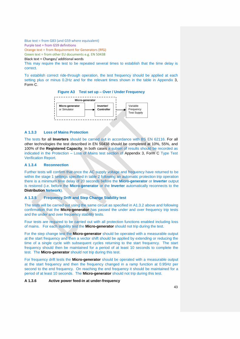
Blue text = from G83 (and G59 where equivalent) Purple text = from G59 definitions
Orange text = from Requirement for Generators (RfG) Green text = from other EU documents e.g. EN 50438
Black text = Changes/ additional words
43
This may require the test to be repeated several times to establish that the time delay is
correct.
To establish correct ride-through operation, the test frequency should be applied at each
setting plus or minus 0.2Hz and for the relevant times shown in the table in Appendix 3,
Form C.
Figure A3 Test set up – Over / Under Frequency
A 1.3.3 Loss of Mains Protection
The tests for all Inverters should be carried out in accordance with BS EN 62116. For all
other technologies the test described in EN 50438 should be completed at 10%, 55%, and
100% of the Registered Capacity. In both cases a subset of results should be recorded as
indicated in the Protection – Loss of Mains test section of Appendix 3, Form C Type Test
Verification Report.
A 1.3.4 Reconnection
Further tests will confirm that once the AC supply voltage and frequency have returned to be
within the stage 1 settings specified in table 2 following an automatic protection trip operation
there is a minimum time delay of 20 seconds before the Micro-generator or Inverter output
is restored (i.e. before the Micro-generator or the Inverter automatically reconnects to the
Distribution Network).
A 1.3.5 Frequency Drift and Step Change Stability test
The tests will be carried out using the same circuit as specified in A1.3.2 above and following
confirmation that the Micro-generator has passed the under and over frequency trip tests
and the under and over frequency stability tests.
Four tests are required to be carried out with all protection functions enabled including loss
of mains. For each stability test the Micro-generator should not trip during the test.
For the step change test the Micro-generator should be operated with a measurable output
at the start frequency and then a vector shift should be applied by extending or reducing the
time of a single cycle with subsequent cycles returning to the start frequency. The start
frequency should then be maintained for a period of at least 10 seconds to complete the
test. The Micro-generator should not trip during this test.
For frequency drift tests the Micro-generator should be operated with a measurable output
at the start frequency and then the frequency changed in a ramp function at 0.95Hz per
second to the end frequency. On reaching the end frequency it should be maintained for a
period of at least 10 seconds. The Micro-generator should not trip during this test.
A 1.3.6 Active power feed-in at under-frequency
Micro-generator
Micro-generator
or Simulator
Inverter/
Controller
Variable
Frequency
Test Supply

Blue text = from G83 (and G59 where equivalent) Purple text = from G59 definitions
Orange text = from Requirement for Generators (RfG) Green text = from other EU documents e.g. EN 50438
Black text = Changes/ additional words
44
EN 50438 shall be complied with in respect of active power feed-in at under-frequency
where the power reduction is in accordance with paragraph 10.4.2 of this EREC G99.
A 1.3.7 Power response to over-frequency
EN 50438 shall be complied with in respect of Power response to over-frequency using a
specific standard frequency threshold of 50.4 Hz and a Droop setting of10%
A 1.4 POWER QUALITY
A 1.4.1 Harmonics
The tests should be carried out as specified in BS EN 61000-3-2 and can be undertaken
with a fixed source of energy at two power levels firstly between 45 and 55% and at 100%
of Registered capacity.
The test must be carried out with a minimum of 2kW of rated Micro-generators. Where an
individual Micro-generator is smaller than 2kW it should be tested as a group. However
where a Micro-generator is designed to be installed singly in an installation then this can be
tested alone, for example a domestic CHP unit. The maximum group size for the test is
3.68kW.
The results for all Inverters should be normalised to a rating of 3.68kW. The Micro-
generator or group shall meet the harmonic emissions of table 1 in BS EN 61000-3-2 with a
scaling factor applied as follows for each harmonic current;
BS EN 61000-3-2 Table 1 current limit × rating of Micro-generator being tested (kW) per
phase / 3.68
A 1.4.2 Power Factor
The test should be undertaken as laid out in EN 50438 with the following three test voltages
230 V –6%, 230V and 230 V +10%.
A 1.4.3 Voltage Flicker
The test must be carried out with a minimum of 2kW of rated Micro-generators. Where an
individual Micro-generator is smaller than 2kW it should be tested as a group. However
where a Micro-generator is designed to be installed singly in an installation then this can be
tested alone, for example a domestic CHP unit. The maximum group size for the test is
3.68kW.
The Micro-generator or group shall meet the required dmax, dc, d(t), Pst, Plt requirements of
BS EN 61000-3-3 with a scaling factor applied as follows for each voltage change
component.
dmax, dc, d(t), Pst, Plt × rating of Micro-generator being tested (kW) per phase / 3.68
The results for groups of Inverters should be normalised to a rating of 3.68kW and to the
standard source impedance. Single Inverters need to be normalised to the standard source
impedance, these normalised results need to comply with the limits set out in Appendix 3,
Form C.

Blue text = from G83 (and G59 where equivalent) Purple text = from G59 definitions
Orange text = from Requirement for Generators (RfG) Green text = from other EU documents e.g. EN 50438
Black text = Changes/ additional words
45
For voltage change and flicker measurements the following simplified formula is to be used
to convert the measured values to the normalised values where the power factor of the
generation output is 0.98 or above. Where it is less than 0.98 then compliance with the full
requirements of BS EN 61000-3-3 is required.
Normalised value = Measured value × reference source resistance/measured source
resistance at test point.
And for units which are tested as a group.
Normalised value = Measured value × reference source resistance/measured source
resistance at test point × 3.68/rating per phase.
Single phase units reference source resistance is 0.4 ohms
Two phase units in a three phase system reference source resistance is 0.4 ohms
Two phase units in a split phase system reference source resistance is 0.24 ohms
Three phase units reference source resistance is 0.24 ohms.
The stopping test should be a trip from full load generation.
The dates and location of the tests need to be noted in Appendix 3, Form C.
Note: For wind turbines, flicker testing should be carried out during the performance tests
specified in IEC 61400-12-1. Flicker data should be recorded from wind speeds of 1m/s
below cut-in to 1.5 times 85% of the rated power. The wind speed range should be divided
into contiguous bins of 1m/s centred on multiples of 1m/s. The dataset shall be considered
complete when each bin includes a minimum of 10 minutes of sampled data. The highest
value of each parameter measured across the entire range of tests shall be recorded.
Note: As an alternative to type testing the Manufacturer of a Micro-generator incorporating
an Inverter may give a guarantee that rates of change of output do not exceed the following
ramp rate limits. Output needs to ramp up at a constant rate.
This exception to site testing does not apply to devices where the output changes in steps of
over 30ms rather than as a ramp function, a site test is required for these units.
Single phase units and two phase units in a three phase system, maximum ramp up
rate 333 watts per second;
Two phase units in a split phase system and three phase units, maximum ramp up
rate 860 watts per second.
It should be noted that units complying with this declaration are likely to be less efficient at
capturing energy during times when the energy source is changing.
For technologies other than wind turbines, testing should ensure that the controls or automatic programs used produce the most unfavourable sequence of voltage changes.
Hydro Micro-generators with manually fixed output or where the output is fixed by
controlling the water flow through the turbine to a steady rate, need to comply with the
maximum voltage change requirements of BS EN 61000-3-2 but do not need to be tested for
Pst or Plt.

Blue text = from G83 (and G59 where equivalent) Purple text = from G59 definitions
Orange text = from Requirement for Generators (RfG) Green text = from other EU documents e.g. EN 50438
Black text = Changes/ additional words
46
Hydro Micro-generators where the output is controlled by varying the load on the generator
using the Inverter and which therefore produces variable output need to comply with the
maximum voltage change requirements of BS EN 61000-3-2 and also need to be tested for
Pst and Plt over a period where the range of flows varies over the design range of the turbine
with a period of at least 2 hours at each step with there being 10 steps from min flow to
maximum flow. Pst and Plt values to recorded and normalised as per the method laid down
in Appendix 3, Form C.
A 1.4.4 DC Injection
DC injection compliance testing in EN 50438 shall be applicable to all Micro-generators
regardless of connection configuration.
A 1.4.5 Overcurrent Protection
Where appropriate the protection shall comply with the requirements of BS7671.
A 1.4.6 Short Circuit Current Contribution for Inverters
Inverter connected Micro-generators generally have small short circuit fault contributions
however DNOs need to understand the contribution that they do make to system fault levels
in order to determine that they can continue to safely operate without exceeding design fault
levels for switchgear and other circuit components.
The following type tests shall be carried out and the results noted in Appendix 3, Form C.
Test circuit
Test procedure
‘A’ and ‘V’ are ammeters and voltmeters used to record the test data required. Component
‘D’ is a resistive load plus resonant circuit as required for the loss of mains test as specified
in BS EN 62116 set up to absorb 100% rated output of the Inverter. Component ‘a’ is an
ammeter used to confirm that all the output from the Inverter is being absorbed by
component D. Components ‘B’ and ‘C’ are set up to provide a voltage of between 10% and
40% of nominal when component ‘C’ carries the rated output of the Inverter in Amps.
Component ‘C’ should be short term rated to carry the load which would appear through it
should it be energised at 253V for at least 1s. Component ‘B’ is to have an impedance of
between 10 and 20 ohms per phase. If components ‘B’ and ‘C’ are short time rated than an
additional switch in series with ‘B’ and ‘C’ can be inserted and arranged to be closed shortly

Blue text = from G83 (and G59 where equivalent) Purple text = from G59 definitions
Orange text = from Requirement for Generators (RfG) Green text = from other EU documents e.g. EN 50438
Black text = Changes/ additional words
47
before the main change over switch shown on the drawing and opened at the end of the test
period. Components ‘B’ and ‘C’ are to have an X to R ratio of 2.5 to 1.
The test is carried out by setting up the Inverter and load ‘D’ to produce and then absorb full
rated output of the Inverter. When zero export is shown by ammeter ‘a’ then the
changeover switch shown is operated connecting the Inverter to the reduced voltage
connection created by components ‘B’ and ‘C’ and disconnecting if from the normal
connection. The make contact is an early make and the break contact a late break so that
the Inverter is not disconnected from a mains connection for any significant time.
The values of voltage and current should be recorded for a period of up to 1 second when
the changeover switch should be returned to the normal position. The voltage and current at
relevant times shall be recorded in the type test report (Appendix 3, Form C) including the
time taken for the Inverter to trip. (It is expected that the Inverter will trip on either loss of
mains or under voltage in less than one second).
A 1.4.7 Short Circuit Current Contribution for Directly Coupled technology
DNOs need to understand the contribution a makes to system fault levels in order to
determine that they can continue to safely operate without exceeding design fault levels for
switchgear and other circuit components.
For non Inverter connected machines the tests in EN 50438 shall be applicable.
For rotating machines and linear piston machines the test should produce a 0 – 2 second
plot of the short circuit current as seen at the Micro-generator terminals.
A 1.4.8 Self-Monitoring - Solid State Disconnection
Some Inverters include solid state switching devices to disconnect from the DNO’s
Distribution Network. In this case 11.1.3 requires the control equipment to monitor the
output stage of the Inverter to ensure that in the event of a protection initiated trip the output
voltage is either disconnected completely or reduced to a value below 50 volts AC. This
shall be verified either by self-certification by the Manufacturer, or additional material shall
be presented to the tester sufficient to allow an assessment to be made.
A 1.4.9 Electromagnetic Compatibility (EMC )
All equipment shall comply with the generic EMC standards: BS EN61000-6-3:
Electromagnetic Compatibility, Generic Emission Standard; and BS EN61000-6-1:
Electromagnetic Compatibility, Generic Immunity Standard.