Embed Size (px)
Citation preview

BLOWER & VACUUM PUMP
Document No. MH1007-00
INSTRUCTION MANUAL
・ Hand this manual to actual blower users.
・ Read and understand this manual before using ITO blowers.
・ No part of this manual may be reproduced in any form, including pho-tocopying or translation into another language, without the prior writ-ten consent of ITO.
IRS(IRT)-300C ・IRS(IRT)-300D ・IRS(IRT)-350C ・IRS(IRT)-350E
IRS(IRT)-400B ・IRS(IRT)-400C ・IRT-400D ・IRT-450B
IRT-450A ・IRT-500B ・IRT-600A

ForewordThank you for purchasing ITO products.
This manual is a user`s guide for the following ITO blower models: IRS(IRT)-300C, IRS(IRT)-
300D, IRS(IRT)-350C, IRS(IRT)-350E, IRS(IRT)-400B, IRS(IRT)-400C, IRT-400D, IRT-450B,
IRT-450A, IRT-500B, and IRT-600A.
Blowers are designed so that atmospheric pressure is maintained on the suction side, and pressure
higher than the atmospheric one is maintained on the discharge side; for vacuum pumps, pressure
lower than the atmospheric one is maintained on the suction side, and atmospheric pressure is main-
tained on the discharge side. Hereafter in this manual, blowers and vacuum pumps are collectively
called “Blowers.” Before using the ITO blower, read this manual thoroughly to understand its struc-
ture, functions, and procedures for its long, safe, and trouble-free operation.
General Precautions
・ Read and understand this manual before using ITO blowers.
・ For safety, read and understand safety precautions.
・ Hand this manual to actual blower users.
・ Keep this manual in a convenient place for quick and easy reference at all times.
・ For safety, follow instructions in this manual.
・ The contents of this manual are subject to change without notice.
・ All rights reserved. No part of this manual may be reproduced in any form, including
photocopying or translation into another language, without the prior written consent of
ITO.
・ Iftherearemissingorincorrectlycollatedpages,contactyourITOdealeroroffice.
・ Ifthismanualislost,contactyourITOdealeroroffice.
Contents
This manual consists of the following chapters. When a reference is made, read and follow it care-
fully.
Chapter 1 GeneralChapter 2 InstallationChapter 3 OperationChapter 4 MaintenanceChapter 5 Troubleshootingi

indicates an action to avoid a hazard.
prohibitsfromuseinacombustibleareaornearopenflame.
indicates a prohibited action to avoid a hazard.
indicates a possibility of an electrical shock.
indicates an action to ground earth lug.
prohibits from touching.
if not avoided, can result in death or injury.
if not avoided, may result in incidents of property
damage.
Signal WordsSafety precautions are categorized into “WARNING” or “CAUTION” as follows.
indicates a caution of rotating parts.
indicates a caution of high temperature.
Safety Symbols
ii
WARNINGCAUTION

Installation
iii
Safety Precautions - Read First -
WARNING
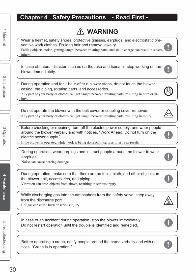
Before operating a crane, notify people around the crane verbally and with no-tices, “Crane is in operation.”
Operate a crane only by a licensed operator.Operation mistake can lead to a drop or a crash, resulting in serious injury.
In case of natural disaster such as earthquake and tsunami, stop working on the blower immediately.
When unpacking, be careful not to drop contents and tools on your feet.Your feet can be injured.
When unpacking, use tools carefully.Injury can result.
Keep your feet and so on away from an electrical drill.Serious injury can result.
Ground earth lug.You can get an electrical shock.
Do not touch cable joints.You can get an electrical shock.
Wiring must be installed only by suitably qualified personnel.You can get an electrical shock.
Wear a helmet, safety shoes, protective glasses, earplugs, and electrostatic pre-ventive work clothes. Fix long hair and remove jewelry.Falling objects, noise, getting caught between rotating parts, and static charge can result in severe injury.

iv
Safety Precautions - Read First -
CAUTIONAfter all protective covers are removed from blower openings, make sure that foreign objects do not enter the blower.Foreign objects may result in blower seize or damage in the casing.
To install multiple blowers on the common floor, isolate blowers separately by different foundations.The common foundation for multiple blowers may cause blower resonance and more noise.
Foundation must be constructed by experienced personnel.Improper foundation may cause blower vibration and noise.
Connect a silencer as close to the blower suction or discharge port as possible.Resonance inside pipings may occur, resulting in noise.
Support the piping adequately so that it does not apply much load to the blower and the piping.Blower or piping may be damaged.
Install a safety valve and a pressure gauge closer to the blower than a gate valve and a check valve.Blower may be damaged.
For blowers equipped with an aftercooler, install a drain separator.Condensed water may enter the piping line.
If the suction side piping is curved, install a drain separator or drain puller.Clogged drain may cause water hammer phenomena, resulting in blower damage.
For a safety valve with its discharge side facing upstream of the blower, attach a cooler.Hot gas may lead to damage in the casing.
For blowers conveying air or gas containing a lot of dust, mount a filter on the suction side to prevent a blower from blocking.Foreign objects may enter the blower resulting in blower seize or damage in the casing.

Operation
v
Safety Precautions - Read First -
WARNING
Before installing accessories and the piping, remove all protective covers and vaporization rust inhibitors from the blower openings.Operation with them inside the blower may cause blower damage.
For blowers with the piping on the suction side, mount a metallic strainer with 30 to 40 mesh on the suction port to prevent foreign objects such as spatter from entering the blower. After trial run, remove the strainer.Foreign objects may result in blower seize or damage in the casing.
Install wiring following a motor manual.Motor may be damaged.
During operation, wear earplugs and instruct people around the blower to wear earplugs.Noise can cause hearing damage.
In case of an accident during operation, stop the blower immediately. Do not restart operation until the trouble is identified and remedied.
Do not operate the blower with the belt cover or coupling cover removed.Any part of your body or clothes can get caught between rotating parts, resulting in injury.
During operation, make sure that there are no tools, cloth, and other objects on the blower unit, accessories, and piping.Vibration can drop objects from above, resulting in serious injury.
During operation and for 1 hour after a blower stops, do not touch the blower casing, the piping, rotating parts, and accessories.Any part of your body or clothes can get caught between rotating parts, resulting in burn or in-jury.
In case of natural disaster such as earthquake and tsunami, stop working on the blower immediately.
Wear a helmet, safety shoes, protective glasses, earplugs, and electrostatic pre-ventive work clothes. Fix long hair and remove jewelry.Falling objects, noise, getting caught between rotating parts, and static charge can result in severe injury.

vi
Safety Precautions - Read First -
CAUTION
While discharging gas into the atmosphere from the safety valve, keep away from the discharge side.Hot gas can cause burn or serious injury.
Before removing a drain plug, remove an oil feed plug carefully to release pres-sure inside the oil case.If the drain plug is removed before the oil feed plug is removed, oil can be splashed, resulting in serious burn.
While checking from the inspection door on the belt cover or coupling cover, do not reach into the door.Your hand can get caught between rotating parts, resulting in serious injury.
Before operation, notify people around the blower verbally and with notices, "Blower is in operation.”
For blowers with the piping on the suction side, mount a metallic strainer with 30 to 40 mesh on the suction port to prevent foreign objects such as spatter from entering the blower. After trial run, remove the strainer.Foreign objects may result in blower seize or damage in the casing.
Before checking or repairing, turn off the electric power supply, and warn people around the blower verbally and with notices, “Work Ahead. Do not turn on the electric power supply.”If the blower is operated while work is being done on it, serious injury can result.
Do not start a blower with drain or seal water left inside the casing.Water hammer phenomena may cause blower damage.
Do not adjust the air capacity by using valves on the suction or the discharge side.The pressure may increase rapidly and blower may be damaged.
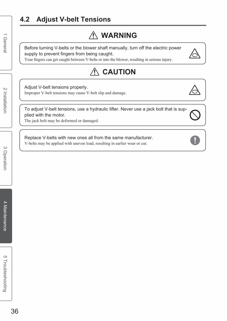
Before turning V-belts or the blower shaft manually, turn off the electric power supply to prevent fingers from being caught.YourfingerscangetcaughtbetweenV-beltsorintotheblower,resultinginseriousinjury.
Operate the blower with an appropriate amount of clean lubricant.An excessive lubricant level may cause abnormal temperature rise due to stirring heat. A lack orstirring heat. A lack or dirt of lubricant may cause blower seize or damage.

vii
Safety Precautions - Read First -
For soundproof boxes with a fan, operate the fan during blower operation.Blower may be damaged.
In areas where temperature drops to 0 degree C or lower, drain all the water in the blower when stopping cooling water or seal water.Water may freeze, resulting in blower damage.
Use ITO recommended lubricant, and follow recommended replacement cycle and quantity.Blower may be damaged.
Adjust V-belt tensions properly.Improper V-belt tensions may cause V-belt slip and damage.
For blowers with gas purges such as one mechanical seal type, follow the design purge pressure specified in specifications.Purge pressure exceeding the rated value may increase pressure abnormally in the side cover and the oil case, and cause blower seize or damage in the casing.
As for cooling water or seal water quality, conform to standard established by the Japan Refrigeration and Air Conditioning Industry Association (JRA).Piping may be clogged or the blower may be damaged.
Before turning on the electric power supply, open valves for piping fully.Turning on the electric power supply with valves closed may cause damage in the casing.
To adjust V-belt tensions, use a hydraulic lifter. Never use a jack bolt that is sup-plied with the motor.The jack bolt may be deformed or damaged.
When a suction strainer or a filter is clogged, clean it.The suction pressure may fall into a vacuum state, leading to blower seize.
Open the cock of the pressure gauge only when reading it.Operating with the cock opened may cause damage to the pressure gauge.

Maintenance
viii
Safety Precautions - Read First -
WARNING
In case of natural disaster such as earthquake and tsunami, stop working on the blower immediately.
Wear a helmet, safety shoes, protective glasses, earplugs, and electrostatic pre-ventive work clothes. Fix long hair and remove jewelry.Falling objects, noise, getting caught between rotating parts, and static charge can result in severe injury.
Do not operate the blower with the belt cover or coupling cover removed.Any part of your body or clothes can get caught between rotating parts, resulting in injury.
During operation and for 1 hour after a blower stops, do not touch the blower casing, the piping, rotating parts, and accessories.Any part of your body or clothes can get caught between rotating parts, resulting in burn or in-jury.
During operation, wear earplugs and instruct people around the blower to wear earplugs.Noise can cause hearing damage.
In case of an accident during operation, stop the blower immediately. Do not restart operation until the trouble is identified and remedied.
While discharging gas into the atmosphere from the safety valve, keep away from the discharge port.Hot gas can cause burn or serious injury.
During operation, make sure that there are no tools, cloth, and other objects on the blower unit, accessories, and piping.Vibration can drop objects from above, resulting in serious injury.
Before operating a crane, notify people around the crane verbally and with no-tices, “Crane is in operation.”
Before checking or repairing, turn off the electric power supply, and warn people around the blower verbally and with notices, “Work Ahead. Do not turn on the electric power supply.”If the blower is operated while work is being done on it, serious injury can result.

ix
Safety Precautions - Read First -
CAUTION
Before removing a drain plug, remove an oil feed plug carefully to release pres-sure inside the oil case.If the drain plug is removed before the oil feed plug is removed, oil can be splashed, resulting in serious burn.
Before adding or changing oil, turn off the electric power supply.Oil can be splashed, resulting in serious burn.
While handling lubricant, keep fire away.Fire can occur, resulting in burn.
Adjust V-belt tensions properly.Improper V-belt tensions may cause V-belt slip and damage.
To adjust V-belt tensions, use a hydraulic lifter. Never use a jack bolt that is sup-plied with the motor.The jack bolt may be deformed or damaged.
Operate a crane only by a licensed operator.Operation mistake can lead to a drop or a crash, resulting in serious injury.
While checking from the inspection door on the belt cover or coupling cover, do not reach into the door.Your hand can get caught between rotating parts, resulting in serious injury.
Before turning V-belts or the blower shaft manually, turn off the electric power supply to prevent fingers from being caught.YourfingerscangetcaughtbetweenV-beltsorintotheblower,resultinginseriousinjury.
Operate the blower with an appropriate amount of clean lubricant.An excessive lubricant level may cause abnormal temperature rise due to stirring heat. A lack orstirring heat. A lack or dirt of lubricant may cause blower seize or damage.

x
Safety Precautions - Read First -
In areas where temperature drops to 0 degree C or lower, drain all the water in the blower when stopping cooling water or seal water.Water may freeze, resulting in blower damage.
Use ITO recommended lubricant, and follow recommended replacement cycle and quantity.Blower may be damaged.
While removing accessories or piping from the blower unit, make sure that for-eign objects do not enter the piping and the blower inside.Foreign objects may result in blower seize or damage in the casing.
For blowers with gas purges such as one mechanical seal type, follow the design purge pressure specified in specifications.Purge pressure exceeding the rated value may increase pressure abnormally in the side cover and the oil case, and cause blower seize or damage in the casing.
Replace V-belts with new ones all from the same manufacturer.V-belts may be applied with uneven load, resulting in earlier wear or cut.
When a suction strainer or a filter is clogged, clean it.The suction pressure may fall into a vacuum state, leading to blower seize.
Open the cock of the pressure gauge only when reading it.Operating with the cock opened may cause damage to the pressure gauge.

Table of Contents
1 General ......................................................................... 1
1.1 Operating Principle ............................................................. 2
1.2 Models ................................................................................ 2
1.3 External View ..................................................................... 3
1.4 Main Parts and Features .................................................... 3
1.5 Unit ..................................................................................... 4
1.6 Standard Layout of Accessories......................................... 4
1.7 Lineup of Accessories ........................................................ 5
1.8 Precautions for Inverter Operation ..................................... 6
2 Installation ..................................................................... 7
2.1 Unpack and Confirm a Purchase ....................................... 9
2.2 Check Installation Requirements...................................... 10
2.3 Foundation Construction .................................................. 11
2.4 Install Blower Unit to Foundation...................................... 12
2.5 Attach Accessories and Pipes .......................................... 13
2.6 Install Wiring ..................................................................... 15
2.7 Place Soundproof Box...................................................... 16
xi
1 General
2 Installation3 O
peration4 M
aintenance5 Troubleshooting

3 Operation .................................................................... 17
3.1 Check before Operation ................................................... 20
3.2 Turn ON Electric Power Supply........................................ 22
3.3 Trial Run (Only first time after installation) ....................... 24
3.4 Operation Check (Daily) ................................................... 26
3.5 Turn OFF Electric Power Supply ...................................... 27
3.6 Store Blower ..................................................................... 28
4 Maintenance ................................................................ 29
4.1 Maintenance Checklist ..................................................... 32
4.2 Adjust V-belt Tensions ..................................................... 36
4.3 Adjust Couplings .............................................................. 38
4.4 Replace Coupling Rubber ................................................ 39
4.5 Add or Change Oil ............................................................ 40
4.6 Clean or Replace Filter on Suction Side .......................... 42
5 Troubleshooting .......................................................... 43
Troubleshooting Checklist .......................................................... 44
Service Warranty ................................................................ 50
Disposal .............................................................................. 50
Blower Specifications ....................................................................51
After-sales Service
xii
1 General
2 Installation3 O
peration4 M
aintenance5 Troubleshooting

MEMO

�
� General
2 Installation3 O
peration4 M
aintenance5 Troubleshooting
Chapter1 GeneralThis chapter provides blower basic information.
�.� Operating Principle ..........................................................2
�.2 Models .............................................................................2
�.3 External View ...................................................................3
�.4 Main Parts and Features .................................................3
�.5 Unit ..................................................................................4
�.6 Standard Layout of Accessories ......................................4
�.7 Lineup of Accessories......................................................5
�.8 Precautions for Inverter Operation...................................6

2
� General
2 Installation3 O
peration4 M
aintenance5 Troubleshooting
1.1 OperatingPrincipleTwo rotors in the casing rotate in opposite directions (in the direction shown by the arrows) to suck gas from
the suction port. The gas is first trapped in spaces between the casing and the rotors, then pushed out of the
discharge port.
1.2 ModelsVarious models are available for a wide range of applications.
Following explains meanings of your ITO blower models.
IRS - 300 C JM
S : Standard
Flange diameter
A, B, C, D, or E: Classified by specifications
No alphabet: Standard (3-lobed rotor)
T : Self air cooled type
J : Side-cover Water Cooled type
M : Parts exposed to gas is plated: Parts exposed to gas is plated Parts exposed to gas is plated
ex: IRS-300C
T : High pressure type
S : Parts exposed to gas is stainless steel: Parts exposed to gas is stainless steel Parts exposed to gas is stainless steel

3
� General
2 Installation3 O
peration4 M
aintenance5 Troubleshooting
1.4 MainPartsandFeaturesMain parts and their features are as follows:
CasingThe discharge port is located on the right-hand viewing from the drive end. For an option, the discharge port is located on the left-hand viewing from the drive end.
Rotor A rotor is not a solid part with shafts cooling-fitted to both ends of the rotor body.
GearGears keep definite clearances between two rotors in the casing, and transmits rotation from the drive rotor to the driven rotor.
LubricationGears and bearings are lubricated with oil.
Drive SystemThe blower and the motor are connected by driving V-belts or couplings. For the belt drive system, pulleys are set on the blower and motor shafts, and then V-belts are set over the pulleys. For the coupling drive system, the blower and the motor shafts are connected by cou-plings.
Sealing SystemShafts are sealed with labyrinth and oil seals. For blowers conveying corrosive gas, shafts are sealed with optional mechanical seals.
1.3 ExternalView
Section ViewExternal View
ex: IRS-300C
Gear end
Drive end
Drive end
Rotor
Suction Port
Discharge Port
Casing

Suction Silencer
Discharge Silencer
Expansion Joint
Safety Valve
Check Valve
Short Pipe for Safety Valve
Pressure Gauge
Sub-Base(option)
Common Base
Belt Cover
Motor
Blower
Vibration Isolating Rubber (option)
Expansion Joint
Safety Valve
Discharge Silencer
Expansion Joint
Suction Silencer
Vacuum Gauge
4
� General
2 Installation3 O
peration4 M
aintenance5 Troubleshooting
1.5 UnitA blower unit is assembled as shown in the illustration below. It is shipped with oil filled.
1.6 StandardLayoutofAccessoriesThe standard layout of accessories is shown in the illustrations below.
Vacuum Pump
ex: IRS-300C
ex: IRS-300C
ex: IRS-300C
Blower

SVHSP
KS
IS
ISL
TOAI
KS TOA
JK TF TEJ
ST
DUO
Discharge Silencer
Expansion Joint
Safety Valve
Check Valve
Short Pipe for Safety Valve
ex: IRS-300C
Suction Silencer
5
� General
2 Installation3 O
peration4 M
aintenance5 Troubleshooting
1.7 LineupofAccessoriesMain blower accessories are shown in the illustrations below.
DS
<Other Accessories>Gate Valve MS StrainerDrain Separator Reduce Short PipeWater Tank Gas FilterSoundproof Box Anchor BoltPressure Gauge Cock for Oil ChangePressure Gauge with Electric ContactWater Hood for Suction SilencerStand for Pressure Gauge Elbow Pipe for Safety Valve Vacuum GaugeLow Pressure GaugeThermometer for BearingThermometer with Electric Contact

6
� General
2 Installation3 O
peration4 M
aintenance5 Troubleshooting
1.8 PrecautionsforInverterOperationTo use an inverter, please observe precautions below.
� Select a special motor for the inverter to be used.
2 Operate the blower within the frequency range specified by ITO.
3 During an inverter operation, resonance resulting in abnormal sound and/or vibration may occur especially to blowers with vibration isolating rubbers. Change frequency to where resonance does not occur.
4 To prevent problem, select a motor and an inverter from the same manufac-turer.

�
1 General
2 Installation3 O
peration4 M
aintenance5 Troubleshooting
Chapter2 InstallationBefore installing a blower unit to the foundation, read and perform sections 2.1 “Unpack and Confirm a Purchase” and 2.2 “Check Installation Requirements.”To install the blower, follow the steps in this chapter.
Tools & Materials Needed
□Specifications □CommonTools
□PinchBar □Scissors
□Cutter
2.1 UnpackandConfirmaPurchase .....................................9
2.2 CheckInstallationRequirements ...................................10
2.3 FoundationConstruction................................................11
2.4 InstallBlowerUnittoFoundation ...................................12
2.5 AttachAccessoriesandPipes .......................................13
2.6 Install Wiring ..................................................................15
2.7 PlaceSoundproofBox ...................................................16

�
1 General
2 Installation3 O
peration4 M
aintenance5 Troubleshooting
Beforeoperatingacrane,notifypeoplearoundthecraneverballyandwithno-tices,“Craneisinoperation.”
Operateacraneonlybyalicensedoperator.Operation mistake can lead to a drop or a crash, resulting in serious injury.
Incaseofnaturaldisasterssuchasearthquakeandtsunami,stopworkingontheblowerimmediately.
Chapter2 SafetyPrecautions -ReadFirst-
WARNINGWearahelmet,safetyshoes,protectiveglasses,earplugs,andelectrostaticpre-ventiveworkclothes.Fixlonghairandremovejewelry.Falling objects, noise, getting caught between rotating parts, and static charge can result in severe injury.

ex:IRS-300C
SafetyValveex:SP
Blowernameplate
Safetyvalvenameplate
CAUTION
Gear end
SAFETY VALVEITEM No.MODEL
SET PRESS.SERIAL No.ITO ENGINEERING CO.,LTD.
kPa
9
1 General
2 Installation3 O
peration4 M
aintenance5 Troubleshooting
2.1 UnpackandConfirmaPurchase
Unpack all packages.
Checkthatyouhavereceivedeverythinglistedinthespecifications.
Checkthatvaluesonnameplatesoftheblowerandthesafetyvalvearethesameas those in the purchace order.
Afterallprotectivecoversareremovedfrombloweropenings,makesurethatforeignobjectsdonotentertheblower.Foreign objects may result in blower seize or damage in the casing.
Whenunpacking,becarefulnottodropcontentsandtoolsonyourfeet.Your feet can be injured.
Whenunpacking,usetoolscarefully.Injury can result.
Check all parts for shipping damage.Checkallpartsforshippingdamage.
Store all the unpacked packages in a placeStorealltheunpackedpackagesinaplacewheretheydonotinterruptworks.
WARNING

Check InstallationRequirements
Thegroundforfoundationislevelandsteady.
Floorspace is400mmorwider fromall round theblowerbaseandaccessories.
Therearenoexplosivesandcombustibles inandaroundtheinstallationarea.
Theinstalltionareaislightenoughtoworkonablower.(Itislightenoughtoreadoillevelclearly.)
Forindoorinstallation,thereareairventswithenoughcapacity.
Forblowersusingcoolingwaterorsealwater,therearefacilitiesforwatersupplyanddrainage.
Acraneisavailablewithmoreloadcapacitythanblowerunitweight.
10
1 General
2 Installation3 O
peration4 M
aintenance5 Troubleshooting
2.2 CheckInstallationRequirementsBefore installation, check that all the following installation requirements are met.

CAUTION
11
1 General
2 Installation3 O
peration4 M
aintenance5 Troubleshooting
Calculate foundation load, soil bearingCalculatefoundationload,soilbearingcapacity,areaofbase,andconcretecompressivestrength,usingcalcuationformulasbelow.
2.3 FoundationConstructionFoundation design and construction require its specialized knowledge. So, foundation must be constructed by experienced personnel. To construct the foundation, meet all requirements described below.
Constructthefoundationwithcapacitiesoffoundationload,soilbearingcapacity,areaofbase,andconcretecompressivestrengthcalculated in step 1.Level and steady the foundation.
Cure and dry the concrete completely.Cureanddrytheconcretecompletely.
Toinstallmultipleblowersonthecommonfloor,isolateblowersseparatelybydifferentfoundations.The common foundation for multiple blowers may cause blower resonance and more noise.
Foundationmustbeconstructedbyexperiencedpersonnel.Improper foundation may cause blower vibration and noise.
・Foundation load MS(kg)
MS 3 × MB
MB:Blowerunitweight(kg)
・Soilbearingcapacityfe(ton/㎡ ) fe 20
・AreaofbaseA (㎡ )
A K × (MB+MS)
fe×103
K:Safetyfactorforeachmodel Blowerwithlargeloadchange:4
Blowerwithsmallloadchange:2
・ConcretecompressivestrengthFc(kg/c㎡ ) Fc 210

WARNING
12
1 General
2 Installation3 O
peration4 M
aintenance5 Troubleshooting
2.4 InstallBlowerUnittoFoundation
Keepyourfeetandsoonawayfromanelectricaldrill.Serious injury can r esult.
Makethelevelnessonthesurfaceofflang-esorthecommonbase,1mmorlessthan1mmper1m..
Pouringgroutintothecommonbasespaceisrecommendedforreducingvibration.
Topourgrout,・ Do not include air into grout.・ Cure tightening bolts so that the blower and the
motor can be removed from the common base for future use.
Alignpulleysorcouplings,referringto 4.2 or 4.3.
Although pulleys or couplings have been factory set, they may be misaligned during transportation or affected by the foundation condition.
CAUTION
Foundationmustbeconstructedbyexperiencedpersonnel.Improper foundation may cause blower vibration and noise.

CAUTION
13
1 General
2 Installation3 O
peration4 M
aintenance5 Troubleshooting
2.5 AttachAccessoriesandPipestoBlower
Connectasilencerasclosetotheblowersuctionordischargeportaspossible.Resonance inside pipings may occur, resulting in noise.
Afterallprotectivecoversareremovedfrombloweropenings,makesurethatforeignobjectsdonotentertheblower.Foreign objects may result in blower seize or damage in the casing.
Beforeinstallingaccessoriesandthepiping,removeallprotectivecoversandvaporizationrustinhibitorsfromthebloweropenings.Operation with them inside the blower may cause blower damage.
Supportthepipingadequatelysothatitdoesnotapplymuchloadtotheblowerand the piping.Blower or piping may be damaged.
Forblowerswiththepipingonthesuctionside,mountametallicstrainerwith30to40meshonthesuctionporttopreventforeignobjectssuchasspatterfromenteringtheblower.Aftertrialrun,removethestrainer.Foreign objects may result in blower seize or damage in the casing.
Installasafetyvalveandapressuregaugeclosertotheblowerthanagatevalveandacheckvalve.Blower may be damaged.
Forblowersequippedwithanaftercooler,installadrainseparator.Condensed water may enter the piping line.
Ifthesuctionsidepipingiscurved,installadrainseparatorordrainpuller.Clogged drain may cause water hammer phenomena, resulting in blower damage.
Forblowersconveyingairorgascontainingalotofdust,mountafilteronthesuctionsidetopreventablowerfromblocking.Foreign objects may enter the blower resulting in blower seize or damage in the casing.
Forasafetyvalvewithitsdischargesidefacingupstreamoftheblower,attachacooler.Hot gas may lead to damage in the casing.

TypeNumberofPipes
Needed
Wet-typevacuumpumpPipingforsealwater
Inlet:1
OilcooledtypePipingforcoolingwater
Inlet:1 Outlet:1
Side-coverwatercooled
type
Pipingforcoolingwater
Inlet:1 Outlet:1
14
1 General
2 Installation3 O
peration4 M
aintenance5 Troubleshooting
Removeallprotectivecoversandvaporizationrustinhibitorsfromtheblowersuction and discharge ports.
Check the arrangement of your blower,Checkthearrangementofyourblower,referringtotheoutlinedrawingandsection1.6"StandardLayoutofAccessories."・ Before connecting accessories to the blower,
check that the flow directions in accessories are correct.
・ For blowers with pipes on the suction side, clean the inside of the pipes, and attach a metallic strainer with 30 to 40 meshes to the blower suction port.
Usingacrane,carefullyliftthepreviouslyconnected suction accessories and connect themtotheblowersuctionport.
Connect and support pipes so that too much load will not be applied to the blower.
Usingacrane,carefullyliftthepreviouslyconnected discharge accessories and connectthemtotheblowerdischargeport.
Connect and support pipes so that too much load will not be applied to the blower.
Connect pipes for cooling water or sealConnectpipesforcoolingwaterorsealwatertotheblower.
<PipesNeeded>
Forblowerswithgaspurges,connectpipesforgaspurges.
TypeNumberofPipes
Needed
StandardInlet:2
(Driveend:1,Gearend:1)
Side-coverwatercooledtype
Inlet:4
(Driveend:2,Gearend:2)
<PipesNeeded>

WARNING
CAUTION
15
1 General
2 Installation3 O
peration4 M
aintenance5 Troubleshooting
2.6 InstallWiring
Turnofftheelectricpowersupply.
Openthecoverofthemotorterminalboxandinstallwiringfollowingamotormanual.
Ground earth lug.
Close the cover of the motor terminal boxClosethecoverofthemotorterminalboxsecurely.
Installwiringfollowingamotormanual.Motor may be damaged.
Ground earth lug.You can get an electrical shock.
Donottouchcablejoints.You can get an electrical shock.
Wiringmustbeinstalledonlybysuitablyqualifiedpersonnel.You can get an electrical shock.

16
1 General
2 Installation3 O
peration4 M
aintenance5 Troubleshooting
2.7 PlaceSoundproofBox
Liftthesoundproofboxusingacrane,andplaceitovertheblowerunitslowly.・ Each soundproof box has its own size and
shape. ・ As for structure and assembly procedure of
split type soundproof boxes, see its drawing or assembly instruction.
Securetheboxtothefoundation.
ex:IRS-300C

17
1 General
2 Installation3 O
peration4 M
aintenance5 Troubleshooting
Chapter3 OperationBefore operation, perform section 3.1 “Check before Operation.” Perform section 3.4 “Operation Check (Daily).” This chapter is essential to maximize safety and performance of a blower, and to minimize trouble. Before first operation after installation, perform section 3.3 “Trial Run.”
Tools & Materials Needed
□ Common Tools □ Vibrometer
□ Ammeter □ Voltmeter
□ Thermometer □ Listening rod
3.1 Check before Operation.................................................20
3.2 Turn ON Electric Power Supply .....................................22
3.3 Trial Run (Only first time after installation) .....................24
3.4 Operation Check (Daily) ................................................26
3.5 Turn OFF Electric Power Supply ...................................27
3.6 Store Blower ..................................................................28

WARNING
18
1 General
2 Installation3 O
peration4 M
aintenance5 Troubleshooting
Chapter3 SafetyPrecautions -ReadFirst-
During operation, wear earplugs and instruct people around the blower to wear earplugs.Noise can cause hearing damage.
In case of an accident during operation, stop the blower immediately. Do not restart operation until the trouble is identified and remedied.
Do not operate the blower with the belt cover or coupling cover removed.Any part of your body or clothes can get caught between rotating parts, resulting in injury.
During operation, make sure that there are no tools, cloth, and other objects on the blower unit, accessories, and piping.Vibration can drop objects from above, resulting in serious injury.
In case of natural disaster such as earthquake and tsunami, stop working on the blower immediately.
Wear a helmet, safety shoes, protective glasses, earplugs, and electrostatic pre-ventive work clothes. Fix long hair and remove jewelry.Falling objects, noise, getting caught between rotating parts, and static charge can result in severe injury.
While discharging gas into the atmosphere from the safety valve, keep away from the discharge port.Hot gas can cause burn or serious injury.
During operation and for 1 hour after a blower stops, do not touch the blower casing, the piping, rotating parts, and accessories.Any part of your body or clothes can get caught between rotating parts, resulting in burn or in-jury.

CAUTION
19
1 General
2 Installation3 O
peration4 M
aintenance5 Troubleshooting
Chapter3 SafetyPrecautions -ReadFirst-
For blowers with the piping on the suction side, mount a metallic strainer with 30 to 40 mesh on the suction port to prevent foreign objects such as spatter from entering the blower. After trial run, remove the strainer.Foreign objects may result in blower seize or damage in the casing.
Do not adjust the air capacity by using valves on the suction or the discharge side.The pressure may increase rapidly and blower may be damaged.
Do not start a blower with drain or seal water left inside the casing.Water hammer phenomena may cause blower damage.
For soundproof boxes with a fan, operate the fan during blower operation.Blower may be damaged.
In areas where temperature drops to 0 degree C or lower, drain all the water in the blower when stopping cooling water or seal water.Water may freeze, resulting in blower damage.
Operate the blower with an appropriate amount of clean lubricant.An excessive lubricant level may cause abnormal temperature rise due to stirring heat. A lack orstirring heat. A lack or dirt of lubricant may cause blower seize or damage.

WARNING
CAUTION
20
1 General
2 Installation3 O
peration4 M
aintenance5 Troubleshooting
3.1 CheckbeforeOperation
Before removing a drain plug, remove an oil feed plug carefully to release pres-sure inside the oil case.If the drain plug is removed before the oil feed plug is removed, oil can be splashed, resulting in serious burn.
Before checking or repairing, turn off the electric power supply, and warn people around the blower verbally and with notices, “Work Ahead. Do not turn on the electric power supply.”If the blower is operated while work is being done on it, serious injury can result.
Use ITO recommended lubricant, and follow recommended replacement cycle and quantity.Blower may be damaged.
Adjust V-belt tensions properly.Improper V-belt tensions may cause V-belt slip and damage.
To adjust V-belt tensions, use a hydraulic lifter. Never use a jack bolt that is sup-plied with the motor.The jack bolt may be deformed or damaged.
When a suction strainer or a filter is clogged, clean it.The suction pressure may fall into a vacuum state, leading to blower seize.
Before turning V-belts or the blower shaft manually, turn off the electric power supply to prevent fingers from being caught.Your fingers can get caught between V-belts or into the blower, resulting in serious injury.

Belt CoverInspection Door
Drain Hole
ex: IRS-300C
Coupling CoverInspection Door
ex: IRS-300C
Oil Feed (plug)
Oil Drain(plug)
Oil Gauge
Gear end
Drain Hole
21
1 General
2 Installation3 O
peration4 M
aintenance5 Troubleshooting
See the oil gauge on the drive end and gear end, and check that the oil level is between the two red lines (1).
If the oil level is below the lower line, remove the oil feed plug, and pour oil until its
level is between the two lines. (see section 4.5.) If the oil level is above the upper line,
remove the oil feed plug to release inside pressure, and then remove the oil drain plug to decrease the oil level until its level is between the two lines.
If the oil is dirty, change oil (see section 4.5).
If the oil is leaking, contact your ITO branch or office.
Open the inspection door, and check V-belt tensions and smooth rotations.
□ Check that the V-belt tensions are proper. (see section 4.2.)
If the V-belt tensions are not proper, adjust the V-belt tensions properly.
□ Rotate V-belts or coupling manually in the operating direction several revolutions. If the V-belts or coupling can be rotated smoothly, it means there are no troubles such as damage in the casing, contacts, or entering of foreign objects.
・ If necessary, remove the belt cover or the coupling cover.
Check the drain holes under the side covers.
For Vacuum Pump
Check that the drain holes are opened. For Blower
Check that the drain holes are closed.
Check that there are no tools, cloth, and other objects on the blower unit, accessories, and pipings.
Check that no bolts are loosened using wrenches.Tighten loose bolts securely.
(1)

CAUTION
WARNING
22
1 General
2 Installation3 O
peration4 M
aintenance5 Troubleshooting
For blowers with a gate valve, turn the handle counterclockwise (in the direction shown by the arrows) slowly to open the valve fully.
For blowers using cooling water or seal water, flow it in the design quantity.
As for the water quality and quantity, see the table below.
For wet type vacuum pump with water tank (WT),
open the valve fully. When the blower starts operation, the water in
the tank starts to flow to the blower. For wet type vacuum pump feeding seal
water directly, to avoid water hammer phenomena, start the
blower and then start feeding seal water.
3.2 TurnONElectricPowerSupply
While checking from the inspection door on the belt cover or coupling cover, do not reach into the door.Your hand can get caught between rotating parts, resulting in serious injury.
Before operation, notify people around the blower verbally and with notices, "Blower is in operation.”
For blowers with gas purges such as one mechanical seal type, follow the design purge pressure specified in specifications.Purge pressure exceeding the rated value may increase pressure abnormally in the side cover and the oil case, and cause blower seize or damage in the casing.
As for cooling water or seal water quality, conform to standard established by the Japan Refrigeration and Air Conditioning Industry Association (JRA).Piping may be clogged or the blower may be damaged.
Before turning on the electric power supply, open valves for piping fully.Turning on the electric power supply with valves closed may cause damage in the casing.

Item JRA CriteriapH 6.5 to 8.2
Electrical Conductivity (25℃ ) mS/m 80 or less
Chloride ion mgCImgCI-/ L 200 or less
Sulfate ion mgSOmgSO4 2-/ L 200 or less
Acid consumption mgCaCOmgCaCO3/ L 100 or less
Total hardness mgCaCOmgCaCO3/ L 200 or less
Calcium hardness mgCaCOmgCaCO3/ L 150 or less
Ionic silica mgSiOmgSiO2/ L 50 or less
<Water �uality Criteria�����Water �uality Criteria���������� (Inlet temperature: 5 to 32℃ )
※ JRA stands for the Japan Refrigeration and Air Conditioning Industry Associateion.
<Needed Water �uantity�����
※Needed water quantity differs depending on each blower specifications.
Unit: L/h
Model Wet typeVacuum Pump Oil Cooled Type
Side-Cover Water
Cooled Type300C 1800 500 2500
300D 1800 500 2500
350C 1800 500 2500
350E 2100 600 4100
400B 2100 600 4100
400C 2100 1000 4100
400D 2400 1000 4100
450B 2400 1000 4100
450A 2700 1000 4100
500B 2700 1000 4100600A 2700 1000 4100
23
1 General
2 Installation3 O
peration4 M
aintenance5 Troubleshooting
For Jacket type and side-cover water cooled type, open the air vent cocks, check all the air has been released from them, and close them.
For blowers using purge gas, adjust the gas to the design purge pressure and purge quantity.
As for the purge pressure and purge quantity, see the specifications.
�uickly turn the electric power supply on and off in order to ensure that the blower rotation direction corresponds to the one shown on the rotating direction seal (found on either the belt cover or the coupling cover).
If the blower rotates in the opposite direction of the design one,
install wiring again, following the motor manual.
Turn on the electric power supply again.
Check for abnormal sounds and vibrations. If there are any abnormal sounds or
vibrations, turn off the electric power supply and identify
the trouble source by checking whether the installation procedures have been correctly followed and whether any foreign objects didn`t enter the blower.
If there are no improper installation procedure and no foreign objects in the blower,
see Chapter 5 "Troubleshooting." Do not restart operation until the trouble is
solved. If the trouble is not solved,
contact your ITO branch or office.
For blowers using purge gas, check that the purge puressure is the rated value.
Purge quantity may decrease during operation. This is not a failure.
For the first operation after installation, go to section 3.3 "Trial Run."
Air Vent Cock
ex: IRS-300CJ
Air Vent Cock

ex: IRS-300C
WARNING
Vertical
AxialHorizontal
Vertical
Axial
Horizontal
24
1 General
2 Installation3 O
peration4 M
aintenance5 Troubleshooting
Operate the blower for ten minutes at no load.
Oil will be spread through gears and bearings.
Check for abnormal sounds and vibrations during step 1.
Gears generate some noise until oil is spread all through gears and bearings. This is not a failure.
If there are any abnormal sounds or vibrations,
turn off the electric power supply and identify the trouble source by checking whether the installation procedures have been correctly followed and whether any foreign objects didn`t enter the blower.
If there are no improper installation procedure and no foreign objects in the blower,
see Chapter 5 "Troubleshooting." Do not restart operation until the trouble is
solved. If the trouble is not solved,
contact your ITO branch or office.
Operate the blower under rated load and perform steps 4 through 7.
Measure the current, and check that it is the motor rated value or less.
If the current is more than the motor rated value,
see Chapter 5 "Troubleshooting." Do not restart operation until the trouble is
solved. If the trouble is not solved,
contact your ITO branch or office.
Measure vibration with a vibrometer, and check that it is the allowable vibration value or less described below.
Measure total amplitude (μm(p-p)) of vibration at 6
points as shown in the illustration below.
3.3 TrialRun(OnlyFirstTimeafterInstallation)
Allowable Vibration Value 114591 / N [μm(p-p)]
N = Blower rotating speed
(ITO Standard)ITO Standard)) ※ The formula above is not applied to special specifications.
If the vibration value is more than the allowable vibration value above,
see Chapter 5 "Troubleshooting." Do not restart operation until the trouble is
solved. If the trouble is not solved,
contact your ITO branch or office.
While checking from the inspection door on the belt cover or coupling cover, do not reach into the door.Your hand can get caught between rotating parts, resulting in serious injury.
Gear end
Drive end

25
1 General
2 Installation3 O
peration4 M
aintenance5 Troubleshooting
Measure temperature on the bearings of the blower, and check that the value is the allowable value or less.
Continue the operation for at least one hour to check abnormalities.
An initial rapid rise in temperature is not a failure.
Bearing temperature allowable value : Ambient temperature + 55degrees C or less (ITO standard)(ITO standard)ITO standard))
If the temperature on the bearings are more than the allowable value,
contact your ITO branch or office.
Check for abnormal sounds. Continue the operation for at least one hour to check
abnormalities. If there are any abnormal sounds,
see Chapter 5 "Troubleshooting." Do not restart operation until the trouble is
solved. If the trouble is not solved,
contact your ITO branch or office.

WARNING
CAUTION
26
1 General
2 Installation3 O
peration4 M
aintenance5 Troubleshooting
3.4 CheckOperation(Daily)
Check following items during operation once a day. If there are any abnormal conditions, turn off the electric power supply immediately, and see Chapter 5
"Troubleshooting." Do not restart operation until the trouble is solved. Ifthetroubleisnotsolved,contactyourITObranchoroffice.
While checking from the inspection door on the belt cover or coupling cover, do not reach into the door.Your hand can get caught between rotating parts, resulting in serious injury.
For blowers with gas purges such as one mechanical seal type, follow the design purge pressure specified in specifications.Purge pressure exceeding the rated value may increase pressure abnormally in the side cover and the oil case, and cause blower seize or damage in the casing.
Check the followings using instruments
Current is the motor rated value or less. (Ammeter)
Vibration is 114591 / Blower rotating speed (ITO standard).(Vibrometer)As for measuring points, see step 5 in section 3.3. Bearing temperature is the ambient temperature + 55degrees C or less. (Thermometer)Suction and discharge pressures are the rated values or less.(Pressure gauge or Vacuum gauge)To change the air capacity or the specified pressure, contact your ITO branch or office.
Purge pressure is the rated value. (Pressure gauge)
Check the followings visuallyThere are no cut or loose on V-belts. (V-belts tend to stretch during the initial operation.)There are no oil leakages.Initial oil ooze is not a leakage but a normal condition.
Cooling water or seal water is flowing without cloggings.
Check the following by hearing
There are no abnormal sounds. (Hearing or Listening rod)
Check the following by sense of odor
There is no strange odor.
Open the cock of the pressure gauge only when reading it.Operating with the cock opened may cause damage to the pressure gauge.

27
1 General
2 Installation3 O
peration4 M
aintenance5 Troubleshooting
For wet-type vacuum pumps, close the wa-ter feed valve, and operate the blower for 30 minutes at no load.
All the remaining water will be dried out.
Turn off the electric power supply.
Check for any abnormal sounds while the blower is decreasing its rotating speed.
If there are any abnormal sounds, see Chapter 5 "Troubleshooting." Do not restart operation until the trouble is
solved. If the trouble is not solved,
contact your ITO branch or office.
3.5 TurnOFFElectricPowerSupply
For blowers with a gate valve, turn the handle clockwise (in the direction shown by the arrows) slowly to close the valve.
Close the valve for cooling water or seal water to stop water running.
If the ambient temperature drops to 0 degree C or lower,
drain water from the blower completely. For blowers other than wet-type vacuum pumps,
leaving water running is no problem to prevent freezing.
Stop the purge gas.

WARNING
28
1 General
2 Installation3 O
peration4 M
aintenance5 Troubleshooting
For blowers using cooling water or seal water, drain water completely.drain water completely.
Protect blowers against corrosion as follows:□ Place a vaporization rust inhibitor in the suction
or the discharge opening. The inhibitor must conform to JIS Z1519 and be
in a bag of cloth.□ Cover the suction and discharge flanges with a
waterproof plywood or a blind flange.
3.6 StoreBlowerIf a blower is not used for a long time, protect the blower as follows:
Waterproof plywood・ Apply antirust to the suction and discharge
flanges.・ Secure the plywood (1) on the flange with wires
(2) as shown in the illustration below.
Blind flange・ Apply antirust to the suction and discharge
flanges.・ Secure the packing (3) and blind flange (4) with
bolts (5) as shown in the illustration below.
Store blowers in a place where they are not exposed to rain and water, and rotate them every few weeks manually to prevent them from seizing.
(1)
(2)
(3)
(4)
(5)
Before turning V-belts or the blower shaft manually, turn off the electric power supply to prevent fingers from being caught.Your fingers can get caught between V-belts or into the blower, resulting in serious injury.

29
1 General
2 Installation3 O
peration4 M
aintenance5 Troubleshooting
Tools & Materials Needed□ Specifications □ �nspection �nst��ctionsInspection Instructions
□ Common Tools □ �istenin�� �o��istenin�� �o�
□ Pinch Ba� □ Tension Ga���e
□ Vib�omete� □ Ammete� □ Voltmete� □ The�momete�
4.1 Maintenance Checklist...................................................32
4.2 A�j�st V-belt Tensions ...................................................36
4.3 A�j�st Co�plin��s ............................................................38
4.4 Replace Co�plin�� R�bbe�..............................................39
4.5 A�� o� Chan��e Oil .........................................................40
4.6 Clean o� Replace Filte� on S�ction Si�e ........................42
Chapter 4 MaintenanceMaintain a blower following this chapter. Improper or any lack of maintenance will cause blower troubles.
WARNING
30
1 General
2 Installation3 O
peration4 M
aintenance5 Troubleshooting
Chapter 4 Safety Precautions - Read First -
�n case of nat��al �isaste� s�ch as ea�thq�ake an� ts�nami, stop wo�kin�� on the blowe� imme�iately.
Wea� a helmet, safety shoes, p�otective ��lasses, ea�pl���s, an� elect�ostatic p�e-ventive wo�k clothes. Fix lon�� hai� an� �emove jewel�y.Falling objects, noise, getting caught between rotating parts, and static charge can result in severe injury.
Do not ope�ate the blowe� with the belt cove� o� co�plin�� cove� �emove�.Any part of your body or clothes can get caught between rotating parts, resulting in injury.
D��in�� ope�ation an� fo� 1 ho�� afte� a blowe� stops, �o not to�ch the blowe� casin��, the pipin��, �otatin�� pa�ts, an� accesso�ies.Any part of your body or clothes can get caught between rotating parts, resulting in burn or in-jury.
D��in�� ope�ation, wea� ea�pl���s an� inst��ct people a�o�n� the blowe� to wea� earplugs.Noise can cause hearing damage.
�n case of an acci�ent ���in�� ope�ation, stop the blowe� imme�iately. Do not �esta�t ope�ation �ntil the t�o�ble is i�entifie� an� �eme�ie�.
While �ischa���in�� ��as into the atmosphe�e f�om the safety valve, keep away f�om the �ischa���e po�t.Hot gas can cause burn or serious injury.
D��in�� ope�ation, make s��e that the�e a�e no tools, cloth, an� othe� objects on the blowe� �nit, accesso�ies, an� pipin��.Vibration can drop objects from above, resulting in serious injury.
Befo�e ope�atin�� a c�ane, notify people a�o�n� the c�ane ve�bally an� with no-tices, “C�ane is in ope�ation.”
Befo�e checkin�� o� �epai�in��, t��n off the elect�ic powe� s�pply, an� wa�n people a�o�n� the blowe� ve�bally an� with notices, “Wo�k Ahea�. Do not t��n on the elect�ic powe� s�pply.”If the blower is operated while work is being done on it, serious injury can result.

31
1 General
2 Installation3 O
peration4 M
aintenance5 Troubleshooting
Chapter 4 Safety Precautions - Read First -
Ope�ate a c�ane only by a license� ope�ato�.Operation mistake can lead to a drop or a crash, resulting in serious injury.

WARNING
CAUTION
Befo�e t��nin�� V-belts o� the blowe� shaft man�ally, t��n off the elect�ic powe� s�pply to p�event fin��e�s f�om bein�� ca���ht.Your fingers can get caught between V-belts or into the blower, resulting in serious injury.
32
1 General
2 Installation3 O
peration4 M
aintenance5 Troubleshooting
4.1 Maintenance ChecklistMaintain blowers and accessories periodically, following a maintenance schedule in this section. If any trouble was found, remedy it following instructions in the Remedy item.
To �isassemble o� assemble a blowe�, contact yo�� �TO b�anch o� office. Defects ca�se� by imp�ope� �isassembly o� assembly by pe�sonnel othe� than �TO o� its �eale�s a�e not wa��ante� by ITO.
While checkin�� f�om the inspection �oo� on the belt cove� o� co�plin�� cove�, �o not reach into the door.Your hand can get caught between rotating parts, resulting in serious injury.
�n a�eas whe�e tempe�at��e ��ops to 0 �e���ee C o� lowe�, ��ain all the wate� in the blowe� when stoppin�� coolin�� wate� o� seal wate�.Water may freeze, resulting in blower damage.
A�j�st V-belt tensions p�ope�ly.Improper V-belt tensions may cause V-belt slip and damage.
Fo� blowe�s with ��as p����es s�ch as one mechanical seal type, follow the �esi��n p����e p�ess��e specifie� in specifications.Purge pressure exceeding the rated value may increase pressure abnormally in the side cover and the oil case, and cause blower seize or damage in the casing.
To a�j�st V-belt tensions, �se a hy��a�lic lifte�. Neve� �se a jack bolt that is s�p-plie� with the moto�.The jack bolt may be deformed or damaged.
Ope�ate the blowe� with an app�op�iate amo�nt of clean l�b�icant.An excessive lubricant level may cause abnormal temperature rise due to stirring heat. A lack orstirring heat. A lack or dirt of lubricant may cause blower seize or damage.

When a s�ction st�aine� o� a filte� is clo����e�, clean it.The suction pressure may fall into a vacuum state, leading to blower seize.
Open the cock of the p�ess��e ��a���e only when �ea�in�� it.Operating with the cock opened may cause damage to the pressure gauge.
33
1 General
2 Installation3 O
peration4 M
aintenance5 Troubleshooting

Blowe�State
Check off How to Check �tem Reme�y Refe� to
Stop
�ookCheck that oil level is p�ope� an� oil is clean an� not leakin��.
�f oil is not eno���h, stop the blowe� an� a�� oil to p�ope� level. �f oil is �i�ty, chan��e oil. �f oil is leakin��, contact yo�� �TO b�anch o� office.
4.5
Touch orTension gauge
Check that V-belt tensions a�e p�ope�.�f the V-belt tensions a�e not p�ope�, stop the blowe� an� a�j�st V-belt tensions.
4.2
TouchCheck that the blowe� shaft can be �otate� smoothly man�ally.
See Chapte� 5 “T�o�bleshootin��.” 5
�ook
Fo� vac��m p�mps, check that the ��ain holes on the si�e cove�s a�e opene�. Fo� blowe�s, check that they are closed.
Fo� vac��m p�mps, open ��ain holes on the si�e cove�s. Fo� blowe�s, close them.
3.1
�ookCheck that the�e a�e no tools o� cloth on the blowe� �nit, accessoi�es, o� piping.
Remove objects p�t on the blowe� �nit, accesso�ies, o� pipin��.
ー
TouchCheck that the�e a�e no loose bolts on the belt cove� an� othe�s.
Ti��hten loose bolts with a w�ench. ー
Maintenance befo�e Ope�ation
Blowe�State
Check off How to Check �tem Reme�y Refe� to
Operation
Ammete�Check that the c���ent is the moto� rated one or less.
See Chapte� 5 “T�o�bleshootin��.” 5
Vib�omete�
Check that the vib�ation is 114591/ blowe� �otatin�� spee� o� less (�TO standard).
See Chapte� 5 “T�o�bleshootin��.” 5
The�mo-mete�
Check that the tempe�at��e on bea�in��s is ambient tempe�at��e + 55 �e���ees C or less.
See Chapte� 5 “T�o�bleshootin��.” 5
P�ess��e&
Vac��m gauge
Check that suction and discharge p�ess��es a�e the �ate� val�es o� less.
See Chapte� 5 “T�o�bleshootin��.” 5
�ookOpen the inspection �oo�, an� check that there is no loose and cut on the V-belts.
Stop the blowe�, an� a�j�st V-belt tensions, o� �eplace V-belts.
4.2
�ook Check that the�e a�e no oil leaka��es. Contact yo�� �TO b�anch o� office. 5
�ookCheck that coolin�� wate� o� seal wate� is flowin�� witho�t clo����in��s.
See Chapte� 5 “T�o�bleshootin��.” 5
P�ess��e gauge
Check that the p����e p�ess��e is the �ate� val�e.
A�j�st the p����e p�ess��e to the �ate� val�e. 3.2
�isten o��istenin��
rod
Check that the�e a�e no abno�mal sounds.
See Chapte� 5 “T�o�bleshootin��.” 5
Smell Check that there are no strange odor. See Chapte� 5 “T�o�bleshootin��.” 5
Daily Maintenance
34
1 General
2 Installation3 O
peration4 M
aintenance5 Troubleshooting

Blowe�State
Check off How to Check �tem Reme�y Refe� to
Stop ー(fo� the fi�st time afte� installation o� afte� ove�ha�l)
Stop the blowe� an� chan��e l�b�icant. 4.5
Blowe�State
Check off How to Check �tem Reme�y Refe� to
Stop ー ー Stop the blowe� an� chan��e l�b�icant. 4.5
Maintenance eve�y 3 months
Maintenance afte� fi�st 500 ope�atin�� ho��s
Blowe�State
Check off How to Check �tem Reme�y Refe� to
Operation
Vac��m gaugeo� �ook
Check that he filte� on the s�ction side is not clogged.
Check with vac��m ��a���e o� vis�ally. �f the filte��f the filte� is clo����e�, stop the blowe�, an� clean o� �eplace the filte�.
4.6
Vac��m gaugeo� �ook
Check that the st�aine� on the s�ctionthe strainer on the suctionon the suction side is not clogged.clogged.
Check with vac��m ��a���e o� vis�ally. �f the�f the st�aine� is clo����e�, stop the blowe�, an� clean the strainer.
ー
Stop
�ookCheck that the�e a�e no loose bolts on the belt cove� an� othe�s.
Ti��hten any loose bolts with a w�ench. ー
Tension gauge
Check that V-belt tensions a�e p�ope�.�f the V-belt tensions a�e not p�ope�, stop the blowe� an� a�j�st V-belt tensions.
4.2
�ook Check that l�b�icant level is p�ope�. A�j�st the l�b�icant level.3.14.5
Monthly Maintenance
Ann�al MaintenanceBlowe�State
Check off How to Check �tem Reme�y Refe� to
Stop
�ook
Pe�fo�m the pe�io�ic ove�ha�l of blowe�s.
・Check the �eplacement cycle of coms�mables in the table below.
・Check that the�e a�e no �ama��e� o� deteriorated parts.
Contact yo�� �TO b�anch o� office. ー
�ookCheck the �eplacement cycle of accesso�ies in the table below.
Contact yo�� �TO b�anch o� office. ー
Replacement Cycle of Cons�mables an� Accesso�ies
Cycle Blowe� Accesso�ies
1 yea�Bea�in��, Oil Seal, O- � in�� ,V-�in��, �aby�inth �in��, Flin��e�, Mechanical Seal
Co�plin�� ��bbe�, V-belt
2 yea� Powe�-�ock R�bbe� expansion joint, Check valve
5 yea� GearP�lley, ��bbe� coolin�� wate� pipes, Safety valve, silence� with so�n� abso�bin�� mate�ial
35
1 General
2 Installation3 O
peration4 M
aintenance5 Troubleshooting
WARNING
CAUTION
36
1 General
2 Installation3 O
peration4 M
aintenance5 Troubleshooting
4.2 Adjust V-belt Tensions
A�j�st V-belt tensions p�ope�ly.Improper V-belt tensions may cause V-belt slip and damage.
Replace V-belts with new ones all f�om the same man�fact��e�.V-belts may be applied with uneven load, resulting in earlier wear or cut.
To a�j�st V-belt tensions, �se a hy��a�lic lifte�. Neve� �se a jack bolt that is s�p-plie� with the moto�.The jack bolt may be deformed or damaged.
Befo�e t��nin�� V-belts o� the blowe� shaft man�ally, t��n off the elect�ic powe� s�pply to p�event fin��e�s f�om bein�� ca���ht.Your fingers can get caught between V-belts or into the blower, resulting in serious injury.

V-belt(Type)
Smalle� P�lley O�tsi�e
Diamete� (mm)
DeflectionFo�ce
(N/one)one)
3 V
67 to 90 1891 to 115 20
116 to 150 23151 to 300 26
5 V180 to 230 58231 to 310 70311 to 400 82
8V300 to 420 153421 to 520 172521 to 630 184
C 1000 mm < 1 mm
C>1000 mm / C < 1/1000
β β < 1/3°
C
ββ
Deflection
Deflection Fo�ce
Span �en��th
P�lley
V-belt
P�lley
(1)(2)
37
1 General
2 Installation3 O
peration4 M
aintenance5 Troubleshooting
T��n off the elect�ic powe� s�pply.
�oosen all ti��htenin�� bolts on the belt cove�, an� �emove the cove�.
Meas��e a span len��th with a tape meas��e, an� ma�k the mi��le of the len��th, �efe��in�� to the ill�st�ation below.
Calc�late a �ecommene� �eflection �sin�� the fo�m�la below.
P�sh the mi��le of the V-belt ma�ke� in step 3 st�ai��ht �own with a tension ��a���e, an� meas��e a �eflection fo�ce when the �eflecion �eaches the �ecommen�e� val�e calculated in step 4.
A�j�st the fo�ce to the val�es specifie� in the table below.
< Deflection Fo�ce >
Deflection (mm) �� Span len��th (mm) �� 0.016mm) �� Span len��th (mm) �� 0.016) �� Span len��th (mm) �� 0.016mm) �� 0.016) �� 0.016�� 0.016 0.016
Ali��n the p�lleys followin�� steps below.1. Measure the differential levels and β between
the blower pulleys (1) and (2).
2. Adjust the differential levels measured in step 1 to the values specified in the table below.
※ Deflection fo�ces in the table above a�e j�st a �efe�ence. Fo� yo�� acc��ate fo�ce, contact yo�� �TO b�anch o� office.
< Allowable Diffe�ential �evels >
Recheck the �eflection fo�ce, �efe��in�� to the steps 5 and 6.
�nstall an� sec��e the belt cove� with the tightening bolts.
Rea�j�st V-belt tensions afte� a few �ays beca�se V-belts ten� to st�etch ���in�� the initial operation.

Co�plin�� Type Bolt size
Ti��htenin�� To�q�e
N・m (k��・m)G 82 to 97 M6 9.8 (1.0)
G 112 to 128 M8 21.6 (2.2)
G 148 to 194 M10 47.0 (4.8)
G 214 to 240 M12 84.3 (8.6)
G 265 to 295 M14 186.0 (19.0)
G 330 to 415 M16 289.0 (29.5)
G 480 to 575 M20 568.0 (58.0)
Co�plin�� TypeO�tsi�e �iamete�
fo� Co�plin��D (mm)
Distance between flan��es
S1±�� (mm)
Deviation
Y (mm)
Deviation
α (`)
Deviation
Z (mm)
G82 82 3�1�1 0.05 3.0 0.07G97 97 3�1�1 0.05 2.5 0.07
G112 112 3.5�1�1 0.07 2.5 0.08G128 128 3.5�1�1 0.07 2.5 0.09G148 148 3.5�1�1 0.07 2.0 0.09G168 168 3.5�1�1 0.10 2.0 0.10G194 194 3.5�1�1 0.10 2.0 0.11G214 214 4�1�1 0.10 2.0 0.12G240 240 4�1�1 0.10 2.0 0.13G265 265 5.5�1�1 0.10 2.0 0.14G295 295 8�2.5�2.5 0.12 2.0 0.14G330 330 8�2.5�2.5 0.12 1.5 0.15G370 370 8�2.5�2.5 0.12 1.5 0.16G415 415 8�2.5�2.5 0.12 1.5 0.18G480 480 8�2.5�2.5 0.12 1.5 0.20G575 575 8�2.5�2.5 0.12 1.5 0.25
90°
Dial Gauge
Tightening bolt
0°
180°
270°
S1 ± ��
Y
Z1
α
Z2
Φ D
Z = Z1 - Z2
38
1 General
2 Installation3 O
peration4 M
aintenance5 Troubleshooting
4.3 Adjust Couplings
Check that co�plin�� bolts have been ti��htene� with the to�q�e val�es specifie� in the table below.
< Co�plin�� allowable �eviations >
Ali��n the co�plin�� so that the �eviations Y an� Z will be within the val�es specifie� in the table below.
How to Obtain Deviation Y Place a dial gauge as shown in the illustration below,
and read the deviation Y on the dial gauge, at 0, 90, 180, and 270 degrees.
How to Obtain Deviation Z Measure deviations Z1 and Z2 between flanges at 2
points of 180 degrees apart, with a thickness gauge or a vernier caliper. Subtract Z2 from Z1.
<Ti��htenin�� To�q�e>

Flan��eCo�plin�� R�bbe�
C�t he�e
Tightening bolt
39
1 General
2 Installation3 O
peration4 M
aintenance5 Troubleshooting
4.4 Replace Coupling Rubber
�oosen ti��htenin�� bolts.
Sli�e the flan��e o�twa��s.
Remove the co�plin�� ��bbe�.
C�t the new co�plin�� ��bbe� as shown in the ill�st�ation below.
Place a new co�plin�� ��bbe�.
P�t the flan��e back in its o�i��inal place.
Ti��hten all ti��htenin�� bolts �ia��onally. First, tighten the bolts lightely, then with the torque
specified in step 1 of section 4.3.

Befo�e �emovin�� a ��ain pl���, �emove an oil fee� pl��� ca�ef�lly to �elease p�es-sure inside the oil case.If the drain plug is removed before the oil feed plug is removed, oil can be splashed, resulting in serious burn.
Use �TO �ecommen�e� l�b�icant, an� follow �ecommen�e� �eplacement cycle an� q�antity.Blower may be damaged.
Man�fact��e� �SO VG 100VG 100G 100 �SO VG 68VG 68G 68
Showa ShellTell�s Oil C100 (Mo�lina Oil 100)Turbo Oil T100
Tell�s Oil C68Turbo Oil T68
Exxon MobilDTE Oil heavyTeresso 100
DTE Oil heavy Me�i�mTeresso 68 68
Nippon Oil FBK Oil RO 100FBK Oil RO 68FBK T��bine RO 68
Japan Ene���yJomo �ath�s 100Jomo R��� T��bine 100
Jomo Hy��o 68Hy��o 68Jomo R��� T��bine 68
Cosmo oilCosmo Allp�s 100Cosmo T��bine S�pe� 100
Cosmo Allp�s 68Cosmo T��bine S�pe� 68
��emits� kosanDaphne S�pe� Oil 100Daphne Turbine 100
Daphne Mechanical Oil 68Daphne Turbine 68
WARNING
CAUTION
40
1 General
2 Installation3 O
peration4 M
aintenance5 Troubleshooting
< Recommen�e� Oils >Recommen�e� Oils > >※ Recommended oil viscosity grade is ISO V�� 100 or ISO V�� �8.V�� 100 or ISO V�� �8.�� 100 or ISO V�� �8.V�� �8.�� �8.
4.5 Add or Change Oil
Befo�e a��in�� o� chan��in�� oil, t��n off the elect�ic powe� s�pply.Oil can be splashed, resulting in serious burn.
While han�lin�� l�b�icant, keep fi�e away.Fire can occur, resulting in burn.
Ope�ate the blowe� with an app�op�iate amo�nt of clean l�b�icant.An excessive lubricant level may cause abnormal temperature rise due to stirring heat. A lack orstirring heat. A lack or dirt of lubricant may cause blower seize or damage.

※ Oil capacities in the table above a�e j�st a �efe�ence. �t may inc�ease o� �ec�ease �epen�in�� on each blowe�.
Model D�ive end
Gear end Fi�st Chan��e F�om Secon�
Chan��e on
�RS(T)-300C�RS(T)-300D�RS(T)-350C
4.9 � 11.3 �
Afte� 500 operating hours(abo�t 20 �ays)
Eve�y 2000 operating hours
(abo�t 3 months)
�RS(T)-350E�RS(T)-400B
7.0 � 17.0 �
�RS(T)-400C�RT-400D�RT-450B�RT-450A�RT-500B�RT-600A
7.8 � 14.0 �
ex: �RS-300C
Oil Fee�(pl���)
Oil Drain(pl���)
Oil Gauge
Gear end
41
1 General
2 Installation3 O
peration4 M
aintenance5 Troubleshooting
A�� oil
T��n off the elect�ic powe� s�pply.
Remove the oil fee� pl���.
A�� oil �ntil its level is between the two �e� lines (1).
P�t the oil fee� pl��� back in its o�i��inal place.
Chan��e oil
T��n off the elect�ic powe� s�pply.
Remove the oil fee� pl���.
Remove the oil ��ain pl��� an� ��ain all the oil.
P�t the oil ��ain pl��� back in its o�i��inal place.
A�� the oil �ntil its level is between the two red lines (1).
As for the oil capacity, see the table below.
< Oil Chan��e �nte�vals & Capacity >
P�t the oil fee� pl��� back in its o�i��inal place.
(1)

While �emovin�� accesso�ies o� pipin�� f�om the blowe� �nit, make s��e that fo�-ei��n objects �o not ente� the pipin�� an� the blowe� insi�e.Foreign objects may result in blower seize or damage in the casing.
CAUTION
42
1 General
2 Installation3 O
peration4 M
aintenance5 Troubleshooting
4.6 Clean or Replace Filter on Suction Side
T��n off the elect�ic powe� s�pply.
�oosen the n�t o� eyen�t (1), an� �emove the lid (2).
Remove the filte� (5) between pe�fo�ate� metals (3) and (4).
Clean o� �eplace the filte� (5). When cleaning the filter,
clean the filter with water or mild detergent, and then dry it completely.
When replacing the filter, replace the filter with a new one.
P�t the filte� (5) an� pe�fo�ate� metals (3)(4) back in thei� o�i��inal place, place the li� (2), an� sec��e it with the n�t o� eyen�t (1).
(1)(2) (4)(3)
(5)
When a s�ction st�aine� o� a filte� is clo����e�, clean it.The suction pressure may fall into a vacuum state, leading to blower seize.

43
1 General
2 Installation3 O
peration4 M
aintenance5 Troubleshooting
Chapter 5 TroubleshootingIf a trouble occurs, turn off the electric power supply immediately, and see Troubleshooting Checklists categorized by symptoms in the next several pages, and perform its corresponding remedies.
If the trouble cause can not be identified, or the trouble can not be corrected even after remedies in this chapter are used, contact your ITO branch or office on the back page.
No. 1 .lo.er .on.t start.lo.er .on.t start ......................................................44
No. 2 .lo.er stops .uring operation.lo.er stops .uring operation....................................45
No. 3 .lo.er sha.t cannot be rotate. .anuall..lo.er sha.t cannot be rotate. .anuall. ...................45
No. 4 .ir capacit. is .ecreasing.ir capacit. is .ecreasing ..........................................45
No. 5 .urrent is too high.urrent is too high ......................................................46
No. 6 .ressure is too high.ressure is too high ...................................................46
No. 7. .bnor.al soun.s are hear..bnor.al soun.s are hear. .......................................46
No. 8. .trange o.or is e.itte..trange o.or is e.itte. ..............................................47.
No. 9. .ibration is too high.ibration is too high....................................................47.
No. 10. Oil or .ater is lea.ingOil or .ater is lea.ing ................................................47.
No. 11 .ischarge te.perature is too high.ischarge te.perature is too high .............................48.
No. 12 .earing te.perature is too high..earing te.perature is too high. ................................48.
No. 13 Outlet te.perature o. cooling .ater is too highOutlet te.perature o. cooling .ater is too high..........49.
No. 14. .oo..... ...... ... .o. ..o......oo..... ...... ... .o. ..o..... .......................................49.

No. 1 .lo.er .on.t startTrouble source .hec. Ite.s .ause an./or Re.e..
Electrical ..ste.
.hec. that all .ires are connecte.. .onnect unconnecte. .ires.
.hec. that the electric po.er suppl. is supplie.. .uppl. the electric po.er suppl..
.hec. that the brea.er is not trippe.. Turn on the brea.er.
.hec. that no .use on the .istribution boar. is blo.n. Replace the blo.n .use .ith a ne. one.
.hec. that the .ires are connecte. correctl.. .onnect .ires correctl..
.hec. that the start-up .etho. is correct. .hec. the start-up .etho..
.hec. that the start-up perio. is set correctl.. For star-.elta start-up, torque .a. be too s.all. ..just the start-up perio..
.hec. that the .ire is thic. enough .or the
.esign current..n. .ire .a. be .a.age.. Replace an. .e.ective .ires .ith ne. ones that are thic. enough .or the .esign current.
.hec. that no .ire is bro.en or .e.ective. Replace the bro.en or .e.ective .ire .ith a ne. one.
.iping ..ste.
.hec. that the pressure is less than the rate. value. .ee No. 6 “.ressure is too high.”
.hec. that the pipe connections are not covere. .ith protective covers or so on. Re.ove all protective covers.
.h.ck .h.. .h. fi..... o. .h. ..uc..o. ...d. ... .o. clogge.. ..... o.. ...p..c. .h. fi......
.hec. that the strainer on the suction si.e is not clogge.. .lean the strainer.
.lo.er
.hec. that there is no cut on the .-belts. Replace the .-belts .ith ne. ones.
.hec. that the blo.er sha.t can be rotate.
.anuall.. .ee No. 3 “.lo.er sha.t cannot be rotate. .anuall..”
.hec. that .ou .on.t hear an. abnor.al soun.s rotating the blo.er sha.t .anuall..
.n. bearing or gear .a. be .orn or the blo.er .a. be d.m....d. .o...c. you.. ITO b....ch o.. offic..
.hec. that there is no contact or .a.age in the casing. .o...c. you.. ITO b....ch o.. offic..
Motor .hec. that there are no abnor.al con.itions .or the .otor.(.ee the .otor .anual.) .o...c. .h. mo.o.. m..uf.c.u..... o.. you.. ITO b....ch o.. offic..
44
1 General
2 Installation3 O
peration4 M
aintenance5 Troubleshooting
Troubleshooting Checklist

No. 2 .lo.er stops .uring operationTrouble source .hec. Ite. .ause an./or Re.e..
.iping ..ste.
.hec. that the pressure is less than the rate. value. .ee No. 6 “.ressure is too high.”
.h.ck .h.. .h. fi..... o. .h. ..uc..o. ...d. ... .o. clogge.. ..... o.. ...p..c. .h. fi......
.hec. that the strainer on the suction si.e is not clogge.. .lean the strainer.
.lo.er
.hec. that there are no .e.ective appearances b. visual chec..
The blo.er .a. be .a.age...o...c. you.. ITO b....ch o.. offic..
.hec. that the blo.er sha.t can be rotate.
.anuall.. .ee No.3 “.lo.er sha.t cannot be rotate. .anuall..”
.hec. that .ou .on.t hear an. abnor.al soun.s rotating the blo.er sha.t .anuall..
.n. bearing or gear .a. be .orn or the blo.er .a. be d.m....d. .o...c. you.. ITO b....ch o.. offic..
.hec. that there is no contact or .a.age in the casing. .o...c. you.. ITO b....ch o.. offic..
Motor .hec. that there are no abnor.al con.itions .or the .otor.(.ee the .otor .anual.)
.ontact the .otor .anu.acturer or .our ITO branch or offic..
No. 3 .lo.er sha.t cannot be rotate. .anuall.Trouble source .hec. Ite.s .ause an./or Re.e..
.lo.er
.hec. that there are no .e.ective appearances b. visual chec..
The blo.er .a. be .a.age...o...c. you.. ITO b....ch o.. offic..
.hec. that there are no .oreign objects insi.e the casing. Re.ove the .oreign objects.
.hec. that there is no corrosion insi.e the casing. .o...c. you.. ITO b....ch o.. offic..
.hec. that there is no contact or .a.age in the casing. .o...c. you.. ITO b....ch o.. offic..
No. 4 .ir capacit. is .ecreasingTrouble source .hec. Ite.s .ause an./or Re.e..
.iping ..ste.
.hec. that the pressure is less than the rate. value.
I. the blo.er is overloa.e., the air capacit. .ecreases..ee No.6 “.ressure is too High.”
.hec. that there are no loose bolts on the .......... Tighten the loose bolts.
.h.ck .h.. .h. fi..... o. .h. ..uc..o. ...d. ... .o. clogge..
I. the blo.er is overloa.e., the air capacit. .ecreases...... o.. ...p..c. .h. fi......
.hec. that the strainer on the suction si.e is notthe strainer on the suction si.e is not clogge..
I. the blo.er is overloa.e., the air capacit. .ecreases..lean the strainer.
.hec. that the sa.et. valve is not activate..the sa.et. valve is not activate.. .o...c. you.. ITO b....ch o.. offic..
.lo.er
.hec. that the spee. o. rotation is not
.ecreasing..n. .-belt .a. be slippe....just .-belt tensions.
.hec. that the blo.er sha.t can be rotate.
.anuall.. .ee No.3 “.lo.er sha.t cannot be rotate. .anuall..”
45
1 General
2 Installation3 O
peration4 M
aintenance5 Troubleshooting

No. 7. .bnor.al soun.s are hear.Trouble source .hec. Ite.s .ause an./or Re.e..
.lo.er
.hec. that there are no loose .-belts. ..just .-belt tensions.
.hec. that lubricant is enough. Too little lubricant .a. cause abnor.al soun.s.... lubricant.
.hec. that the oil is not .irt.. .hange oil.
.hec. that the blo.er sha.t can be rotate.
.anuall.. .ee No.3 “.lo.er sha.t cannot be rotate. .anuall..”
.hec. that .ou .on.t hear an. abnor.al soun.s rotating the blo.er sha.t .anuall..
.earing or gear .ear, poor .echanical seal contact or
.ear, or blo.er .a.age .a. result. .ontact .our ITO b....ch o.. offic..
.hec. that there is no contact or .a.age in the casing. .o...c. you.. ITO b....ch o.. offic..
.hec. that the coupling rubber is not .orn. Replace the coupling rubber.
.iping ..ste.
.hec. that the pressure is less than the rate. value.
.lo.er overloa. .a. cause abnor.al soun.s
.ee No.6 “.ressure is too high.”
.hec. that there are no loose bolts on the .......... Tighten the loose bolts.
.hec. that there is no trans.itte. noise. .over the noise source .ith lagging.
.hec. that there are no resonances in the piping. .orrect piping supports.
No. 6 .ressure is too highTrouble source .hec. Ite.s .ause an./or Re.e..
.iping ..ste.
.hec. that the gate valve is opene. .ull.. Open the gate valve .ull..
.hec. that the piping is not clogge.. .lean the insi.e o. the piping.
Instru.ent.hec. that there are no abnor.al con.itions .or the pressure gauge.(.ee the pressure gauge .anual.)
.ontact the pressure gauge .anu.acturer or .our ITO b....ch o.. offic..
No. 5 .urrent is too highTrouble source .hec. Ite.s .ause an./or Re.e..
.iping ..ste.
.hec. that the pressure is less than the rate. value. .ee No. 6 “.ressure is too high.”
.h.ck .h.. .h. fi..... o. .h. ..uc..o. ...d. ... .o. clogge.. ..... o.. ...p..c. .h. fi......
.hec. that the strainer on the suction si.e is not clogge.. .lean the strainer.
.lo.er
.hec. that the blo.er sha.t can be rotate.
.anuall.. .ee No.3 “.lo.er sha.t cannot be rotate. .anuall..”
.hec. that .ou .on.t hear an. abnor.al soun.s rotating the blo.er sha.t .anuall..
.n. bearing or gear .a. be .orn or the blo.er .a. be d.m....d. .o...c. you.. ITO b....ch o.. offic..
.hec. that there is no contact or .a.age in the casing. .o...c. you.. ITO b....ch o.. offic..
Motor .hec. that there are no abnor.al con.itions .or the .otor.(.ee the .otor .anual.)
.ontact the .otor .anu.acturer or .our ITO branch or offic..
Instru.ent .hec. that there are no abnor.al con.itions .or the a..eter.(.ee the a..eter .anual.)
.ontact the a..eter .anu.acturer or .our ITO branch or offic..
46
1 General
2 Installation3 O
peration4 M
aintenance5 Troubleshooting
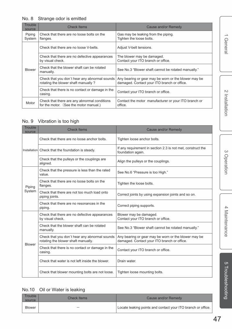
No. 8. .trange o.or is e.itte.Trouble source .hec. Ite.s .ause an./or Re.e..
.iping ..ste.
.hec. that there are no loose bolts on the ..........
Gas .a. be lea.ing .ro. the piping.Tighten the loose bolts.
.lo.er
.hec. that there are no loose .-belts. ..just .-belt tensions.
.hec. that there are no .e.ective appearances b. visual chec..
The blo.er .a. be .a.age...o...c. you.. ITO b....ch o.. offic..
.hec. that the blo.er sha.t can be rotate.
.anuall.. .ee No.3 “.lo.er sha.t cannot be rotate. .anuall..”
.hec. that .ou .on.t hear an. abnor.al soun.s rotating the blo.er sha.t .anuall. ?
.n. bearing or gear .a. be .orn or the blo.er .a. be d.m....d. .o...c. you.. ITO b....ch o.. offic..
.hec. that there is no contact or .a.age in the casing. .o...c. you.. ITO b....ch o.. offic..
Motor .hec. that there are an. abnor.al con.itions .or the .otor.(.ee the .otor .anual.)
.ontact the .otor .anu.acturer or .our ITO branch or offic..
No. 9. .ibration is too highTrouble source .hec. Ite.s .ause an./or Re.e..
Installation
.hec. that there are no loose anchor bolts. Tighten loose anchor bolts.
.hec. that the .oun.ation is stea... I. an. require.ent in section 2.3 is not .et, construct the .oun.ation again.
.hec. that the pulle.s or the couplings are aligne.. .lign the pulle.s or the couplings.
.iping ..ste.
.hec. that the pressure is less than the rate. value. .ee No.6 “.ressure is too High.”
.hec. that there are no loose bolts on the .......... Tighten the loose bolts.
.hec. that there are not too .uch loa. onto piping joints. .orrect joints b. using expansion joints an. so on.
.hec. that there are no resonances in the piping. .orrect piping supports.
.lo.er
.hec. that there are no .e.ective appearances b. visual chec..
.lo.er .a. be .a.age..
.o...c. you.. ITO b....ch o.. offic..
.hec. that the blo.er sha.t can be rotate.
.anuall.. .ee No.3 “.lo.er sha.t cannot be rotate. .anuall..”
.hec. that .ou .on.t hear an. abnor.al soun.s rotating the blo.er sha.t .anuall..
.n. bearing or gear .a. be .orn or the blo.er .a. be d.m....d. .o...c. you.. ITO b....ch o.. offic..
.hec. that there is no contact or .a.age in the casing. .o...c. you.. ITO b....ch o.. offic..
.hec. that .ater is not le.t insi.e the blo.er. .rain .ater.
.hec. that blo.er .ounting bolts are not loose. Tighten loose .ounting bolts.
No.10. Oil or .ater is lea.ingTrouble source .hec. Ite.s .ause an./or Re.e..
.lo.er - Loc... ...k.... po..... ..d co...c. you.. ITO b....ch o.. offic..
47.
1 General
2 Installation3 O
peration4 M
aintenance5 Troubleshooting

No.12 .earing te.perature is too highTrouble source .hec. Ite.s .ause an./or Re.e..
.iping ..ste.
.hec. that the suction te.perature is less than the rate. value. Lo.er the te.perature to the rate. value or less.
.hec. that the pressure is less than the rate. value. .ee No.6 “.ressure is too High.”
.h.ck .h.. .h. fi..... o. .h. ..uc..o. ...d. ... .o. clogge.. ..... o.. ...p..c. .h. fi......
.hec. that the strainer on the suction si.e is not clogge.. .lean the strainer.
.lo.er
.hec. that lubricant quantit. is proper. ..just the lubricant quantit..
.hec. that lubricant t.pe is correct. Use ITO reco..en.e. lubricant.
.hec. that cooling .ater is enough. .ee No.13 “Outlet te.perature o. cooling .ater is too high” ..d No.14. “.oo..... ...... ... .o. ..o......”
.hec. that there are no .e.ective appearances b. visual chec..
The blo.er .a. be .a.age...o...c. you.. ITO b....ch o.. offic..
.hec. that the blo.er sha.t can be rotate.
.anuall.. .ee No.3 “.lo.er sha.t cannot be rotate. .anuall..”
.hec. that .ou .on.t hear an. abnor.al soun.s rotating the blo.er sha.t .anuall..
.n. bearing or gear .a. be .orn or the blo.er .a. be d.m....d. .o...c. you.. ITO b....ch o.. offic..
.hec. that there is no contact or .a.age in the casing. .o...c. you.. ITO b....ch o.. offic..
Instru.ent.hec. that there are no abnor.al con.itions .or the ther.o.eter. (.ee the ther.o.eter .anual.)
.ontact the ther.o.eter .anu.acturer or .our ITO branch o.. offic..
No.11 .ischarge te.perature is too highTrouble source .hec. Ite.s .ause an./or Re.e..
.iping ..ste.
.hec. that the suction te.perature is less than the rate. value. Lo.er the te.perature to the rate. value or less.
.hec. that the pressure is less than the rate. value. .ee No.6 “.ressure is too High.”
.h.ck .h.. .h. fi..... o. .h. ..uc..o. ...d. ... .o. clogge.. ..... o.. ...p..c. .h. fi.....
.hec. that the strainer on the suction si.e is not clogge.. .lean the strainer.
Instru.ent.hec. that there are no abnor.al con.itions .or the ther.o.eter.(.ee the ther.o.eter .anual.)
.ontact the ther.o.eter .anu.acturer or .our ITO branch o.. offic..
48.
1 General
2 Installation3 O
peration4 M
aintenance5 Troubleshooting

No.13 Outlet te.perature o. cooling .ater is too highTrouble source .hec. Ite.s .ause an./or Re.e..
.lo.er
.hec. that the cooling .ater quantit. is enough. ..just the cooling .ater quantit. to the rate. value.
.hec. that the Inlet te.perature o. the cooling
.ater is less than the rate. value. Lo.er the te.perature to the rate. value or less.
.hec. that the suction te.perature is less than the rate. value. Lo.er the te.perature to the rate. value or less.
.hec. that the pressure is less than the rate. value. .ee No.6 “.ressure is too High.”
.hec. that lubricant quantit. is proper. ..just the lubricant quantit..
.hec. that lubricant t.pe is correct. Use ITO reco..en.e. lubricant.
Instru.ent.hec. that there are no abnor.al con.itions .or the ther.o.eter.(.ee the ther.o.eter .anual)
.ontact the ther.o.eter .anu.acturer or .our ITO branch o.. offic..
No.14 .oo..... ...... ... .o. ..o.....Trouble source .hec. Ite.s .ause an./or Re.e..
.ooling .ater .iping
.hec. that the gate valve is opene.. Open the gate valve.
.hec. that piping is not clogge.. .lean the insi.e o. the piping.
.hec. that hoses are not curve.. .traighten the..
.hec. that the .ater quantit. an. pressure are proper. ..just .ater quantit. an. pressure properl..
Instru.ent .hec. that there are no abnor.al con.itions .or .h. ..o. .....h..(S.. .h. ..o. .....h. m..u...)
.o...c. .h. ..o. .....h. m..uf.c.u..... o.. you.. ITO b....ch o.. offic..
49.
1 General
2 Installation3 O
peration4 M
aintenance5 Troubleshooting

50.
1 General
2 Installation3 O
peration4 M
aintenance5 Troubleshooting
Service Warranty
Basic Warranty Conditions
1 ITO Engineering Co.,Ltd. , not otherwise specified, warrants any part of ITO Blower against defects in design, materials, and workmanship for one year from the date of the blower arrival. Within the warranty period, we adjust, repair, or replace any defects under normal use free of charge.
This warranty applies only when the blower is properly used in accordance with instructions in manuals,
the nameplate, and others. This warranty does not apply under the following conditions.
(1) Defects or malfunctions resulting from failure to properly store, operate, or maintain the unit in accordance with this manual.
(2) Defects resulting from failure to use parts recommended by ITO.(3) Defects caused by adjustment, repair, or modification by someone other than ITO authorized
personnel.(4) Defects rusulting from failure to use water in conformity to water quality specified in this manual.(5) Defects caused by accidental fire, flood, earthquake, lightening, and the like.(6) A breakdown or damage caused by foreign objects, abnormal pressure.
2 This warranty is limited to adjustment, repair, and replacement of defected parts. Damage secondary to the first is not applicable. Price of the warranty is whitin that of the defected part.3 Consumables such as rubber and plastic are not applicable.
We recommend that a spare blower is prepared in case of emergency.
DisposalDispose of a blower as a general industrial waste, complying with local regulations.

※ See the table above just as a reference.※ For detail specifications, see your blower nameplate or specifications.※ Item “Weight” shows the blower body weight. Values in ( ) show IRT type blower body weights.
51
Blower Specifications Model Flange Rotation Suction Air Pressure Output Weight Diameter Speed Capacity (min-1) (m3/min) (kPa) (kW) (kg)
Standard Blower IRS(T)-300C 300A 500~ 1200 45.4~ 148 10~ 70 15.9~ 198 2140 (2360)IRS(T)-300D 300A 500~ 1200 57.1~ 182 10~ 70 19.4~ 243 2360 (2570)IRS(T)-350C 350A 500~ 1100 71.7~ 205 10~ 70 23.5~ 272 2760 (2860)IRS(T)-350E 350A 500~ 1100 80.1~ 225 10~ 70 23.6~ 294 3460 (3620)IRS(T)-400B 400A 500~ 1000 110~ 274 10~ 70 30.8~ 357 3960 (4150)IRS(T)-400C 400A 500 ~ 850 141~ 276 10~ 70 41.7~ 368 5010 (5310)IRT-400D 400A 500 ~ 850 176~ 345 10~ 70 51.4~ 458 (5570)IRT-450B 450A 500 ~ 850 215~ 418 10~ 70 60.9~ 551 (6670)IRT-450A 450A 500 ~ 850 251~ 487 10~ 70 70.1~ 640 (7020)IRT-500B 500A 500 ~ 850 276~ 525 10~ 60 74.6~ 594 (7590)IRT-600A 600A 500 ~ 850 276~ 525 10~ 60 74.6~ 594 (7610)
Side-Cover Water Cooled Type BlowerIRS(T)-300CJ 300A 500~ 1200 41.6~ 135 80~ 100 93.6~ 278 2190 (2410)IRS(T)-300DJ 300A 500~ 1200 52.7~ 167 80~ 100 114~ 341 2410 (2610)IRS(T)-350CJ 350A 500~ 1100 66.7~ 188 80~ 100 140~ 383 2810 (2900)IRS(T)-350EJ 350A 500~ 1100 74.9~ 207 80~ 100 152~ 416 3510 (3660)IRS(T)-400BJ 400A 500~ 1000 103~ 251 80~ 100 203~ 505 4010 (4200)IRS(T)-400CJ 400A 500 ~ 850 135~ 257 80~ 100 246~ 517 5080 (5370)IRT-400DJ 400A 500 ~ 850 170~ 322 80~ 100 306~ 644 (5630)IRT-450BJ 450A 500 ~ 850 207~ 390 80~ 100 368~ 775 (6730)IRT-450AJ 450A 500 ~ 850 242~ 456 80~ 100 427~ 901 (7080)
Dry Type Vacuum PumpIRS(T)-300C 300A 500~ 1200 41.7~ 147 -10~ -50 15.9~ 144 2140 (2360)IRS(T)-300D 300A 500~ 1100 52.8~ 182 -10~ -50 19.4~ 177 2360 (2570)IRS(T)-350C 350A 500~ 1100 66.9~ 204 -10~ -50 23.5~ 199 2760 (2860)IRS(T)-350E 350A 500~ 1100 75.1~ 224 -10~ -50 23.6~ 213 3460 (3620)IRS(T)-400B 400A 500~ 1000 103~ 274 -10~ -50 30.8~ 259 3960 (4150)IRS(T)-400C 400A 500 ~ 850 135~ 276 -10~ -50 41.7~ 269 5010 (5310)IRT-400D 400A 500 ~ 850 170~ 344 -10~ -50 51.4~ 334 (5570)IRT-450B 450A 500 ~ 850 208~ 417 -10~ -50 60.9~ 402 (6670)IRT-450A 450A 500 ~ 850 243~ 486 -10~ -50 70.1~ 466 (7020)IRT-500B 500A 500 ~ 850 264~ 525 -10~ -50 74.6~ 501 (7590)IRT-600A 600A 500 ~ 850 264~ 525 -10~ -50 74.6~ 501 (7610)
Dry Type Vacuum Pump (Self Air Cooled Type) IRS(T)-300CT 300A 500~ 1200 36.7~ 140 -30~ -60 38.1~ 171 2140 (2360)IRS(T)-300DT 300A 500~ 1200 46.9~ 173 -30~ -60 46.7~ 210 2360 (2570)IRS(T)-350CT 350A 500~ 1100 60.0~ 194 -30~ -60 57.0~ 235 2760 (2860)IRS(T)-350ET 350A 500~ 1100 68.0~ 214 -30~ -60 60.4~ 254 3460 (3620)IRS(T)-400BT 400A 500~ 1000 94.8~ 261 -30~ -60 80.2~ 308 3960 (4150)IRS(T)-400CT 400A 500 ~ 850 128~ 265 -30~ -60 100~ 319 5010 (5310)IRT-400DT 400A 500 ~ 850 161~ 331 -30~ -60 124~ 396 (5570)IRT-450BT 450A 500 ~ 850 197~ 402 -30~ -60 149~ 477 (6670)IRT-450AT 450A 500 ~ 850 231~ 469 -30~ -60 172~ 553 (7020)IRT-500BT 500A 500 ~ 850 252~ 507 -30~ -60 185~ 595 (7590)IRT-600AT 600A 500 ~ 850 252~ 507 -30~ -60 185~ 595 (7610)
Wet Type Vacuum PumpIRS(T)-300C 300A 500~ 1200 50.7~ 151 -10~ -60 17.2~ 175 2140 (2360)IRS(T)-300D 300A 500~ 1200 63.3~ 186 -10~ -60 20.9~ 215 2360 (2570)IRS(T)-350C 350A 500~ 1100 78.9~ 209 -10~ -60 25.3~ 241 2760 (2860)IRS(T)-350E 350A 500~ 1100 87.5~ 230 -10~ -60 25.1~ 258 3460 (3620)IRS(T)-400B 400A 500~ 1000 119~ 280 -10~ -60 32.5~ 313 3960 (4150)IRS(T)-400C 400A 500 ~ 850 148~ 281 -10~ -60 45.0~ 327 5010 (5310)IRT-400D 400A 500 ~ 850 186~ 351 -10~ -60 55.4~ 406 (5570)IRT-450B 450A 500 ~ 850 226~ 425 -10~ -60 65.6~ 488 (6670)IRT-450A 450A 500 ~ 850 263~ 495 -10~ -60 75.2~ 565 (7020)IRT-500B 500A 500 ~ 850 286~ 534 -10~ -60 79.9~ 608 (7590)IRT-600A 600A 500 ~ 850 286~ 534 -10~ -60 79.9~ 608 (7610)

Head Office & Factory2-12 Saiwai-cho, Shimizu-ku, Shizuoka-shi, Shizuoka 424-0923, Japan TEL: +81-54-334-2141 FAX: +81-54-337-0034
Tokyo Branch��hi�a Ser�ice �enter��hi�a Ser�ice �enter�hi�a Ser�ice �enter664-6 Naganumahara-cho, Inage-ku, Chiba-shi, Chiba 263-0001, Japan TEL: +81-43-215-2930 FAX: +81-43-259-4941TEL: +81-43-215-2930 FAX: +81-43-259-4941+81-43-215-2930 FAX: +81-43-259-494143-215-2930 FAX: +81-43-259-4941+81-43-259-494143-259-4941
Osaka Branch401 Higobashiseiwa-BLDG., 1-15-10 Edobori, Nishi-ku, Osaka-shi, Osaka 550-0002, Japan TEL: +81-6-6443-6531 FAX: +81-6-6459-4333TEL: +81-6-6443-6531 FAX: +81-6-6459-4333+81-6-6443-6531 FAX: +81-6-6459-43336-6443-6531 FAX: +81-6-6459-4333+81-6-6459-43336-6459-4333 Shimizu Office2-12 Saiwai-cho, Shimizu-ku, Shizuoka-shi, Shizuoka 424-0923, Japan TEL: +81-54-334-2145 FAX: +81-54-334-4990+81-54-334-2145 FAX: +81-54-334-499054-334-2145 FAX: +81-54-334-4990+81-54-334-499054-334-4990
Kyushu Office102 Castle Kawakubo, 2-4-5 Kawakubo, Oonozyo-shi, Fukuoka 816-0905, Japan TEL: +81-92-514-1717 FAX: +81-92-514-1720+81-92-514-1717 FAX: +81-92-514-172092-514-1717 FAX: +81-92-514-1720+81-92-514-172092-514-1720
SIAM ITO ENGINEERING �O., LTD. Bangkok in Thailand TEL: +66-38-717-170 FAX: +66-38-717-174 TEL: +66-38-717-170 FAX: +66-38-717-174+66-38-717-170 FAX: +66-38-717-17466-38-717-170 FAX: +66-38-717-174+66-38-717-17466-38-717-174
After-sales ServiceITO Engineering Co., Ltd. keeps track of all after-sales service history based on ITO original history sheets for each blower. To order periodic maintenance service, repair service, or parts, contact your ITO branch or office.
Printed in JapanIto Engineering Co., Ltd. ©®
http:��www.ito-eng.co.jp�ITO Engineering �o., Ltd.