Embed Size (px)
Citation preview
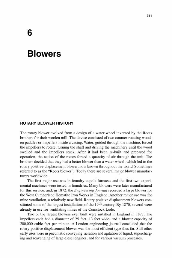
6
Blowers
RotaRy BloweR HistoRy
The rotary blower evolved from a design of a water wheel invented by the Roots brothers for their woolen mill. The device consisted of two counter-rotating wood-en paddles or impellers inside a casing. Water, guided through the machine, forced the impellers to rotate, turning the shaft and driving the machinery until the wood swelled and the impellers stuck. After it had been re-built and prepared for operation, the action of the rotors forced a quantity of air through the unit. The brothers decided that they had a better blower than a water wheel, which led to the rotary positive-displacement blower, now known throughout the world (sometimes referred to as the “Roots blower”). Today there are several major blower manufac-turers worldwide.
The first major use was in foundry cupola furnaces and the first two experi-mental machines were tested in foundries. Many blowers were later manufactured for this service, and, in 1872, the Engineering Journal recorded a large blower for the West Cumberland Hematite Iron Works in England. Another major use was for mine ventilation, a relatively new field. Rotary positive displacement blowers con-stituted some of the largest installations of the 19th century. By 1870, several were already in use for ventilating mines of the Comstock Lode.
Two of the largest blowers ever built were installed in England in 1877. The impellers each had a diameter of 25 feet, 13 feet wide, and a blower capacity of 200,000 cubic feet per minute. A London engineering journal concluded that the rotary positive displacement blower was the most efficient type thus far. Still other early uses were in pneumatic conveying, aeration and agitation of liquid, supercharg-ing and scavenging of large diesel engines, and for various vacuum processes.
351
Of the many services to which the blowers were applied, perhaps the most spectacular was in a subway constructed in 1867 beneath Broadway Avenue in New York City. The blower had an iron casing 22 feet high and impellers 16 feet long. The “Western Tornado,” as the blower was called, provided the power for a 22-seat passenger car which ran on tracks between Murray and Warren Streets. The car was literally blown to one end, then sucked back on its return trip by the action of the unit. The system was the subject of an article in The American Heritage of Invention & Technology.
technical Details
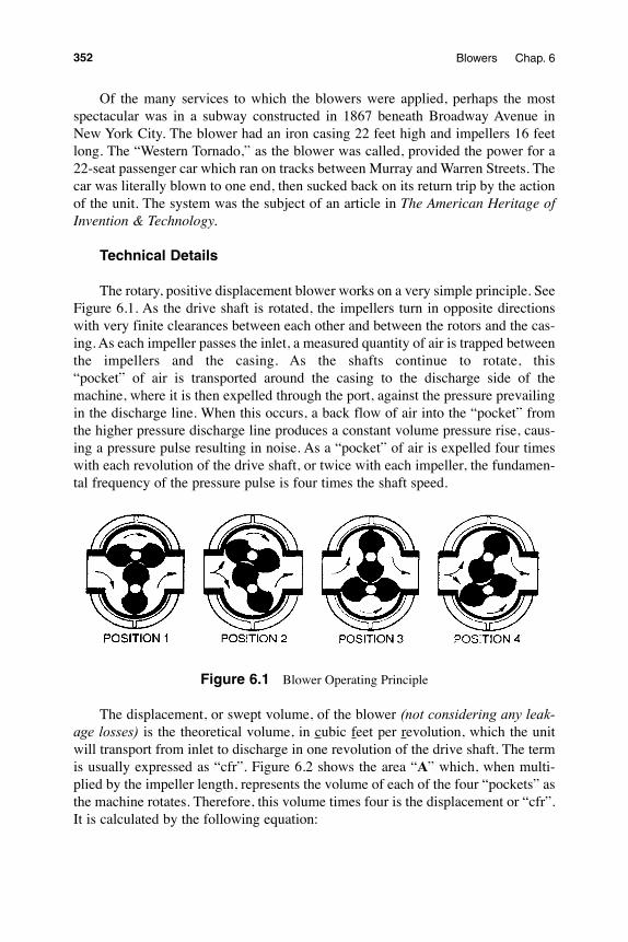
The rotary, positive displacement blower works on a very simple principle. See Figure 6.1. As the drive shaft is rotated, the impellers turn in opposite directions with very finite clearances between each other and between the rotors and the cas-ing. As each impeller passes the inlet, a measured quantity of air is trapped between the impellers and the casing. As the shafts continue to rotate, this “pocket” of air is transported around the casing to the discharge side of the machine, where it is then expelled through the port, against the pressure prevailing in the discharge line. When this occurs, a back flow of air into the “pocket” from the higher pressure discharge line produces a constant volume pressure rise, caus-ing a pressure pulse resulting in noise. As a “pocket” of air is expelled four times with each revolution of the drive shaft, or twice with each impeller, the fundamen-tal frequency of the pressure pulse is four times the shaft speed.
Figure 6.1 Blower Operating Principle
The displacement, or swept volume, of the blower (not considering any leak-age losses) is the theoretical volume, in cubic feet per revolution, which the unit will transport from inlet to discharge in one revolution of the drive shaft. The term is usually expressed as “cfr”. Figure 6.2 shows the area “A” which, when multi-plied by the impeller length, represents the volume of each of the four “pockets” as the machine rotates. Therefore, this volume times four is the displacement or “cfr”. It is calculated by the following equation:
352 Blowers Chap. 6
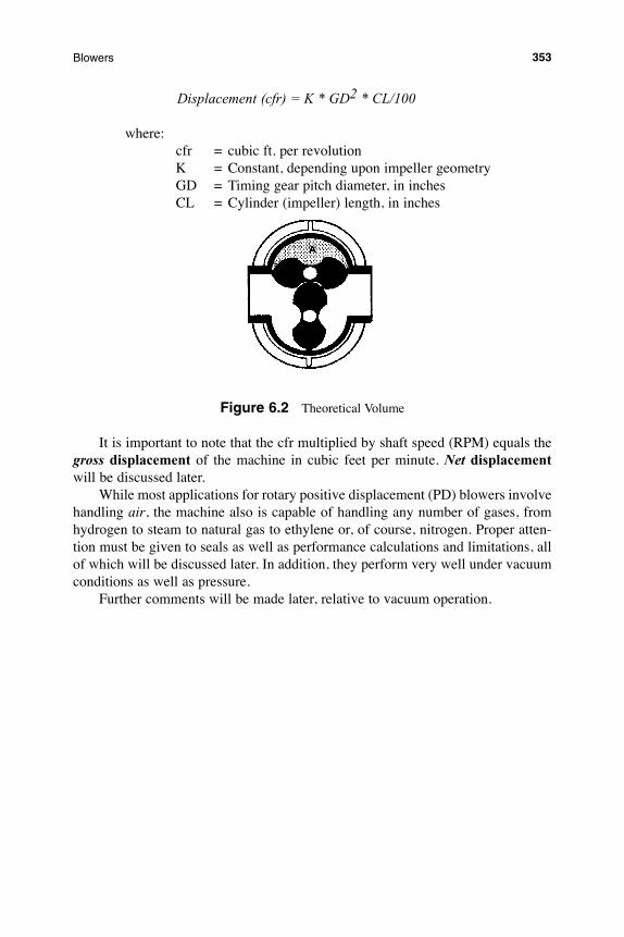
Displacement (cfr) = K * GD2 * CL/100
where: cfr = cubic ft. per revolution K = Constant, depending upon impeller geometry GD = Timing gear pitch diameter, in inches CL = Cylinder (impeller) length, in inches
Figure 6.2 Theoretical Volume
It is important to note that the cfr multiplied by shaft speed (RPM) equals the gross displacement of the machine in cubic feet per minute. Net displacement will be discussed later.
While most applications for rotary positive displacement (PD) blowers involve handling air, the machine also is capable of handling any number of gases, from hydrogen to steam to natural gas to ethylene or, of course, nitrogen. Proper atten-tion must be given to seals as well as performance calculations and limitations, all of which will be discussed later. In addition, they perform very well under vacuum conditions as well as pressure.
Further comments will be made later, relative to vacuum operation.
353Blowers
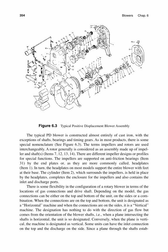
Figure 6.3 Typical Positive Displacement Blower Assembly
The typical PD blower is constructed almost entirely of cast iron, with the exceptions of shafts, bearings and timing gears. As in most products, there is some special nomenclature (See Figure 6.3). The terms impellers and rotors are used interchangeably. A rotor generally is considered as an assembly made up of impel-ler and shaft(s) (Items 7, 12, 13, 14). There are different impeller designs or profiles for special functions. The impellers are supported on anti-friction bearings (Item 31) by the end plates or, as they are more commonly called, headplates (Item 1). In turn, the headplates on most models support the entire blower with feet at their base. The cylinder (Item 2), which surrounds the impellers, is held in place by the headplates, completes the enclosure for the impellers and also contains the inlet and discharge ports.
There is some flexibility in the configuration of a rotary blower in terms of the locations of gas connections and drive shaft. Depending on the model, the gas connections can be either on the top and bottom of the unit, on the sides or a com-bination. When the connections are on the top and bottom, the unit is designated as a “Horizontal” machine and when the connections are on the sides, it is a “Vertical” machine. The designation has nothing to do with the direction of gas flow but comes from the orientation of the blower shafts, i.e., when a plane intersecting the shafts is horizontal, the unit is so designated. Conversely, when the plane is verti-cal, the machine is designated as vertical. Some units can have the inlet connection on the top and the discharge on the side. Since a plane through the shafts estab-
354 Blowers Chap. 6
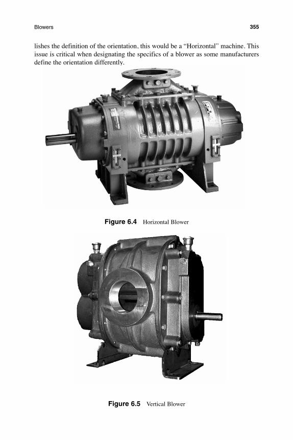
lishes the definition of the orientation, this would be a “Horizontal” machine. This issue is critical when designating the specifics of a blower as some manufacturers define the orientation differently.
Figure 6.4 Horizontal Blower
Figure 6.5 Vertical Blower
355Blowers
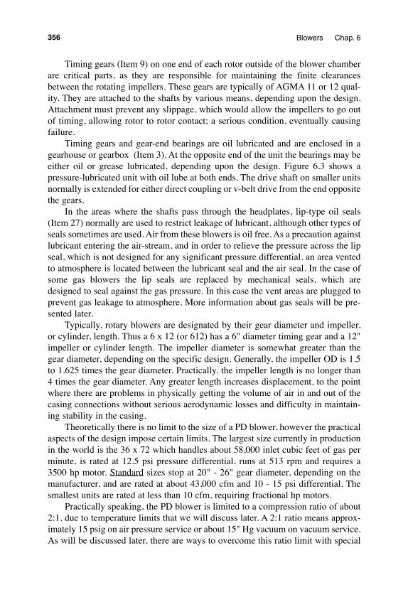
Timing gears (Item 9) on one end of each rotor outside of the blower chamber are critical parts, as they are responsible for maintaining the finite clearances between the rotating impellers. These gears are typically of AGMA 11 or 12 qual-ity. They are attached to the shafts by various means, depending upon the design. Attachment must prevent any slippage, which would allow the impellers to go out of timing, allowing rotor to rotor contact; a serious condition, eventually causing failure.
Timing gears and gear-end bearings are oil lubricated and are enclosed in a gearhouse or gearbox (Item 3). At the opposite end of the unit the bearings may be either oil or grease lubricated, depending upon the design. Figure 6.3 shows a pressure-lubricated unit with oil lube at both ends. The drive shaft on smaller units normally is extended for either direct coupling or v-belt drive from the end opposite the gears.
In the areas where the shafts pass through the headplates, lip-type oil seals (Item 27) normally are used to restrict leakage of lubricant, although other types of seals sometimes are used. Air from these blowers is oil free. As a precaution against lubricant entering the air-stream, and in order to relieve the pressure across the lip seal, which is not designed for any significant pressure differential, an area vented to atmosphere is located between the lubricant seal and the air seal. In the case of some gas blowers the lip seals are replaced by mechanical seals, which are designed to seal against the gas pressure. In this case the vent areas are plugged to prevent gas leakage to atmosphere. More information about gas seals will be pre-sented later.
Typically, rotary blowers are designated by their gear diameter and impeller, or cylinder, length. Thus a 6 x 12 (or 612) has a 6" diameter timing gear and a 12" impeller or cylinder length. The impeller diameter is somewhat greater than the gear diameter, depending on the specific design. Generally, the impeller OD is 1.5 to 1.625 times the gear diameter. Practically, the impeller length is no longer than 4 times the gear diameter. Any greater length increases displacement, to the point where there are problems in physically getting the volume of air in and out of the casing connections without serious aerodynamic losses and difficulty in maintain-ing stability in the casing.
Theoretically there is no limit to the size of a PD blower, however the practical aspects of the design impose certain limits. The largest size currently in production in the world is the 36 x 72 which handles about 58,000 inlet cubic feet of gas per minute, is rated at 12.5 psi pressure differential, runs at 513 rpm and requires a 3500 hp motor. Standard sizes stop at 20" - 26" gear diameter, depending on the manufacturer, and are rated at about 43,000 cfm and 10 - 15 psi differential. The smallest units are rated at less than 10 cfm, requiring fractional hp motors.
Practically speaking, the PD blower is limited to a compression ratio of about 2:1, due to temperature limits that we will discuss later. A 2:1 ratio means approx-imately 15 psig on air pressure service or about 15" Hg vacuum on vacuum service. As will be discussed later, there are ways to overcome this ratio limit with special
356 Blowers Chap. 6
designs. In terms of working pressure, these units normally are limited to 25 psig, as a standard. Under certain conditions, or with specific sizes or designs, however, this rule also can be circumvented.
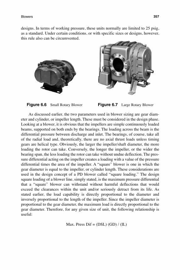
Figure 6.6 Small Rotary Blower Figure 6.7 Large Rotary Blower
As discussed earlier, the two parameters used in blower sizing are gear diam-eter and cylinder, or impeller length. These must be considered in the design phase. Looking at a blower, it is obvious that the impellers are simple continuously loaded beams, supported on both ends by the bearings. The loading across the beam is the differential pressure between discharge and inlet. The bearings, of course, take all of the radial load and, theoretically, there are no axial thrust loads unless timing gears are helical type. Obviously, the larger the impeller/shaft diameter, the more loading the rotor can take. Conversely, the longer the impeller, or the wider the bearing span, the less loading the rotor can take without undue deflection. The pres-sure differential acting on the impeller creates a loading with a value of the pressure differential times the area of the impeller. A “square” blower is one in which the gear diameter is equal to the impeller, or cylinder length. These considerations are used in the design concept of a PD blower called “square loading.” The design square loading of a blower line, simply stated, is the maximum pressure differential that a “square” blower can withstand without harmful deflections that would exceed the clearances within the unit and/or seriously detract from its life. As stated earlier, the load capability is directly proportional to the diameter and inversely proportional to the length of the impeller. Since the impeller diameter is proportional to the gear diameter, the maximum load is directly proportional to the gear diameter. Therefore, for any given size of unit, the following relationship is useful:
Max. Press Dif = (DSL) (GD) / (IL)
357Blowers
where: Max. Pressure Differential is in psi Design Square Load is in psi Gear Diameter is in inches Impeller Length is in inchesThus, within a line designed with a square loading of 18 psi, a size 10 x 10
would be capable of a maximum pressure differential of 18 psi, while a 10 x 30 in the same line would be rated at 6 psi. The design considerations that come into play when determining the square loading of a line of blowers are:
Shaft size, material and stiffness Bearing size, rating and location Impeller profile and stiffness Gear design and location Gear attachment designAs the bearings on a PD blower carry the radial load, and since the radial load
is directly proportional to the pressure differential, bearing load, therefore, is dependent on the design square load.
thermodynamic Cycle theory
PRESSURE POWERD
A
C
B
FLOW
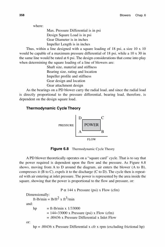
Figure 6.8 Thermodynamic Cycle Theory
A PD blower theoretically operates on a “square card” cycle. That is to say that the power required is dependent upon the flow and the pressure. As Figure 6.8 shows, moving from A to D around the diagram, air enters the blower (A to B), compresses it (B to C), expels it to the discharge (C to D). The cycle then is repeat-ed with air entering at inlet pressure. The power is represented by the area inside the square, showing that the power is proportional to the flow and pressure, or:
P α 144 x Pressure (psi) x Flow (cfm)Dimensionally: ft-lb/min = lb/ft2 x ft3/min and: hp = ft-lb/min x 1/33000 = 144÷33000 x Pressure (psi) x Flow (cfm) = .00436 x Pressure Differential x Inlet Flow or: hp = .00436 x Pressure Differential x cfr x rpm (excluding frictional hp)
358 Blowers Chap. 6
limitations
As with any machinery, there are limits to the manner in which a PD blower can be applied. Specifically, these limits are:
Temperature rise Discharge temperature Pressure differential Working pressure Shaft speed
temperature Rise
Temperature rise is defined as the difference between inlet and discharge tem-perature. The increase in temperature is caused by the heat of compression, in accordance with the gas laws, including inefficiencies. Going back to the basic blower construction, it is evident that the impellers “see,” alternately, inlet and then discharge temperature. Their average temperature should be the average between those two values. The casing, on the other hand, will “see” not only inlet and dis-charge temperature, but will also “see” ambient temperature on the external sur-faces. The cylinder, therefore, will be at a lower average temperature than the impellers. Therefore, the impellers will tend to grow more, and faster, than the cylinder, creating a differential expansion, which causes the end clearance between the impeller and the headplates to reduce. Further temperature rise due to increased compression ratio will result in impeller-headplate contact, which will ultimately cause failure of the blower.
Discharge temperature
Several problems occur when the discharge temperature increases to levels higher than recommended. Firstly, due to heat transfer, the lubricant begins to break down at temperatures above its limits. When this occurs, not only does the lubricant lose its qualities, but carbon begins to form, causing further problems to oil flow and rubbing surfaces. The higher temperatures also can result in reduced bearing life, as the bearing materials begin to break down due to the impaired lubricity. Gear life can be affected for the same reasons. There also could be damaging ther-mal distortion of parts, causing misalignment and, perhaps, even failure, due to the extreme temperatures. Finally, seal failure likely would occur as the materials in the seal parts are subjected to the higher thermal stresses.
Pressure Differential
There are specific problems related to exceeding the pressure differential design ratings. We have related bearing life to pressure differential, and that the bearings take the radial load caused by the pressure differential. Added load, there-
359Blowers
fore, will bring about reduced bearing life. Increased pressure differential also causes increased shaft stresses and there must be limits to avoid excessive deflec-tions and possible fracture of the shafts.
The torque requirements of a rotary blower vary directly as do the pressure differential. Since the timing gears see this torque, increased pressure differential means increased loads on the gears. The gears have a finite design life, dependent on pitch line speed and loading. Therefore, gear life is dependent upon pressure differential.
Due to the deflections resulting from increased pressure differential, the clear-ances on the inlet side of the unit, between the impellers and the cylinder, begin to close up. This happens on the inlet side, because the force that causes the deflection is equal to the pressure differential from discharge to inlet times the projected area of the impeller. The pressure is higher on the discharge side, thereby forcing the impellers to deflect toward the inlet. If deflection causes the available clearances to be taken up, contact is made and the resulting rub can cause failure.
Increased compression ratio causes increased temperature rise. Assuming that the inlet pressure remains constant, an increase in pressure differential means an increase in compression ratio and, therefore, an increase in temperature rise. Excessive temperature rise causes the end clearances to close up, causing the even-tual rub and, thence, failure.
As previously stated, there is a definite pressure pulse that occurs four or six times per revolution depending on number of lobes per rotor. This pulse is propor-tional to the pressure differential and causes vibration and noise. Therefore, as the pressure differential is increased, noise and vibration also increase. These vibra-tions and noise levels are reasonable when held within limits, but excessive values can be destructive.
working Pressure
The normal maximum working pressure of a typical PD blower is 25 psig. This limit basically is a result of the casing design. Exceeding the design value can result in potentially damaging distortions, internal rubs and possibly even casing fracture. As with any vessel containing air or gas, one must be extremely cautious about controlling internal, or working, pressures.
shaft speed
Every blower is limited on shaft rotational speed. Displacement and torque are proportional to rotational speed, affecting both bearing life and gear life. In addi-tion, noise and vibration will increase, perhaps to dangerous levels, if the shaft speed is allowed to rise beyond reasonable values. Also, as the rpm is increased, the stresses on the rotating parts go up, approximately as the square of the rpm. Excessive rpm, then, can result in break-up of the unit.
360 Blowers Chap. 6
slip
This term in blowers refers to the leakage flow from discharge to inlet. Finite clearances must be maintained within the PD blower for it to continue operating at design efficiency.
As the blower impellers rotate, carrying the “pockets” of air from the inlet to the discharge, one side of each impeller is exposed to discharge pressure while the other side sees inlet pressure. There is a clearance, or leakage path, between the two impellers and between the impellers and the casing. These leakage paths, along with the pressure differential, allow a certain amount of air from the pocket to “slip” back through from discharge to inlet. The ends of the impellers, in close proximity to the headplates, are further leak paths. The total of these leak paths must be accounted for in performance calculations. It has been shown for specific applications that about 2/3 of the slip occurs between the impellers and between the impellers and cylinder and 1/3 around the ends of the impellers. We will discuss the specifics of this relationship later.
A feature of some air-moving and compressing devices is a ratio called “Volumetric Efficiency”, or “VE.” We can apply this characteristic to the rotary blower and slip becomes a part of the definition. VE is defined as the ratio, expressed as a percentage, of the actual to theoretical (or ideal) displacement (flow), or:
VE(%) = 100 x Actual Flow/Theoretical Flow (Displacement) where Actual Flow is defined as actual inlet flow and Theoretical Flow is cfr x rpm.
Since slip detracts from the theoretical displacement and since slip can be expressed as flow, the above becomes:
VE(%) = 100 x (Theoretical Flow-Slip Flow)/Theoretical Flow.
Gross and net displacement were discussed previously. The Theoretical Flow from the above is gross displacement and the Actual Flow is net. Typical VE’s for a rotary blower range from about 95% for a large machine at maximum rpm/mini-mum pressure differential to as low as 65% for a small machine at low rpm/high pressure differential.
A means of reducing slip is to inject a controlled amount of water or other fluid into the inlet of the blower along with the gas stream. This liquid disperses inside the casing and tends to fill up the clearances, effectively reducing the available slip paths. This concept is used most effectively on vacuum service where compression ratios, and therefore slips, are relatively high when operating dry. The addition of the liquid also reduces temperature rise and tends to flush out any contaminants, which might otherwise build up on the internals. Certain precautions must be con-sidered, however, and these will be treated later.
361Blowers
DesiGN FeatURes
Some of the blower’s design features have already been discussed , however there are many variations, not only from model to model, but also from manufacturer to manufacturer. These include:
impellers
The most important part of the blower is the impeller. Impellers normally are cast grey iron with a typical variation being cast ductile iron for greater strength. In extreme cases, where corrosion or erosion resistance is required, they also can be cast or fabricated of stainless steel or coated with various materials. The other variation in impellers is in the profile. The typical impeller lobe profile is gener-ated by an involute curve. This curve allows the impellers to rotate in conjunction with and in close proximity to one another without coming into contact. It is an efficient profile and relatively easy to form on various machine tools. When the involute impeller rotates, however, there is a point at which the clearance locus jumps from one point to another. As this occurs, there is a brief instant when a small volume is trapped between the impellers. While this causes no problems on normal air service, if there are significant or uncontrolled amounts of liquid entrained in the gas stream, the effect is an attempt to compress this liquid as the impellers continue to rotate. Liquid does not compress, so the impellers are forced apart by the liquid for an instant. This can be damaging to the unit as it may cause internal contact. Where there is a possibility of significant liquid entrainment, slightly dif-ferent profiles can be selected.
These water-handling profiles are designed to allow a rolling or sweeping motion to the clearance loci rather than the jumping motion as with the involute. Therefore, there is no opportunity for the liquid to cause the deflection as with the involute profile. Various profiles for this purpose do not provide as much displace-ment as the involute. In addition, they are more difficult to form in the manufactur-ing process. These profiles are very useful, however, when applying the PD blower on vacuum service. In this service, a liquid, usually water, is purposely sprayed into the blower inlet to aid in sealing the clearances to make the machine more efficient and, as a bonus, the water keeps the unit cool, as it carries away the heat of com-pression, allowing the unit to achieve a higher compression ratio.
Staging these units permits the compound machine to meet requirements as low as 27" Hg. vacuum (3" Hg. absolute) or to a level near the vapor pressure of the sealing liquid. While these special impeller profiles have been developed for water-sealed applications, recent efforts to utilize the involute profile with a reduced, controlled water flow have been quite successful.
Three standard profiles are utilized by most manufacturers - Involute, High Displacement Liquid Passing, and Cycloidal, the latter two typically used for water-sealed vacuum service. The three profiles are shown in Figure 6.9. Recalling the previous discussion on displacement, which is calculated as:
362 Blowers Chap. 6
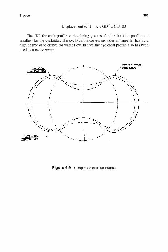
Displacement (cfr) = K x GD2 x CL/100
The “K” for each profile varies, being greatest for the involute profile and smallest for the cycloidal. The cycloidal, however, provides an impeller having a high degree of tolerance for water flow. In fact, the cycloidal profile also has been used as a water pump.
Figure 6.9 Comparison of Rotor Profiles
363Blowers
three lobe Blowers
More recent designs include three lobe blowers with some changes in operat-ing characteristics.
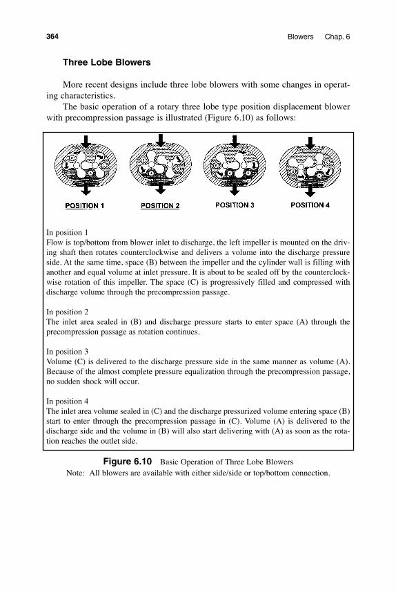
The basic operation of a rotary three lobe type position displacement blower with precompression passage is illustrated (Figure 6.10) as follows:
In position 1Flow is top/bottom from blower inlet to discharge, the left impeller is mounted on the driv-ing shaft then rotates counterclockwise and delivers a volume into the discharge pressure side. At the same time, space (B) between the impeller and the cylinder wall is filling with another and equal volume at inlet pressure. It is about to be sealed off by the counterclock-wise rotation of this impeller. The space (C) is progressively filled and compressed with discharge volume through the precompression passage.
In position 2The inlet area sealed in (B) and discharge pressure starts to enter space (A) through the precompression passage as rotation continues.
In position 3Volume (C) is delivered to the discharge pressure side in the same manner as volume (A). Because of the almost complete pressure equalization through the precompression passage, no sudden shock will occur.
In position 4The inlet area volume sealed in (C) and the discharge pressurized volume entering space (B) start to enter through the precompression passage in (C). Volume (A) is delivered to the discharge side and the volume in (B) will also start delivering with (A) as soon as the rota-tion reaches the outlet side.
Figure 6.10 Basic Operation of Three Lobe BlowersNote: All blowers are available with either side/side or top/bottom connection.
364 Blowers Chap. 6
Bearings
The bearings, which support the impellers, typically are of the anti-friction type, either ball or some form of roller. Depending upon such parameters as square loading, rpm, lubrication options and others, the manufacturer attempts to design the most appropriate bearing into the unit, keeping in mind life, size, bearing clear-ance, cost, availability and load carrying capability. Also important to the bearing system is control of thrust or side movement of the impellers. There is no inherent thrust generated by the impellers as they rotate but, due to the expansion process brought about by the temperature rise within the blower, other considerations must be taken into account to control axial movement of the rotors. Additionally, when operating at the higher speeds of today’s PD blowers, a slight contact of impeller to headplate likely will continue in a degenerative mode, with contact causing temperature, which, in turn causes further expansion and more contact, leading eventually to failure. A positive control of the axial position of the impellers is mandatory and some thrust capability in the chosen bearing system is necessary.
The use of a V-belt drive system causes severe side loads on the drive shaft and bearings and such operation must be considered in the bearing design. Bearing life can be grossly affected when V-belt drives are used in lieu of direct-connection. Some manufacturers use an extra bearing on the drive shaft when such drives are to be applied. Another solution is to use a “jack-shaft” for the blower sheave and direct couple the shaft to the blower with a flexible coupling. This is a complicated arrangement but does accomplish the desired result of reducing the drive shaft bearing load.
lubrication
Because the blower is equipped with rolling element bearings and gears, some form of lubricant must be provided. Generally, the gears are located on the end opposite the drive and are lubricated with oil, along with the bearings on that end. The bearings on the drive end may be either grease or oil lubricated, depending on the design and the temperatures at which the blower is expected to operate. Due to the action of the gears, typically there is adequate splashing action on the gear end so that no auxiliary slinger is needed to throw the oil onto the bearings. If the blower is oil lubricated on the drive end, a slinger usually is required to obtain the proper splashing action to direct the oil onto the bearings. On so-called splash-lubricated machines, there is no need for pumps, coolers, piping, relief valves, etc. in the lube system. Such a system, therefore, is quite simple and, other than peri-odic oil changes, is also fairly maintenance free. Operation at high temperatures for extended periods of time will cause deterioration of the lubricant, requiring more frequent changes.
365Blowers
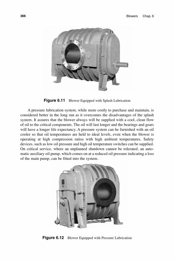
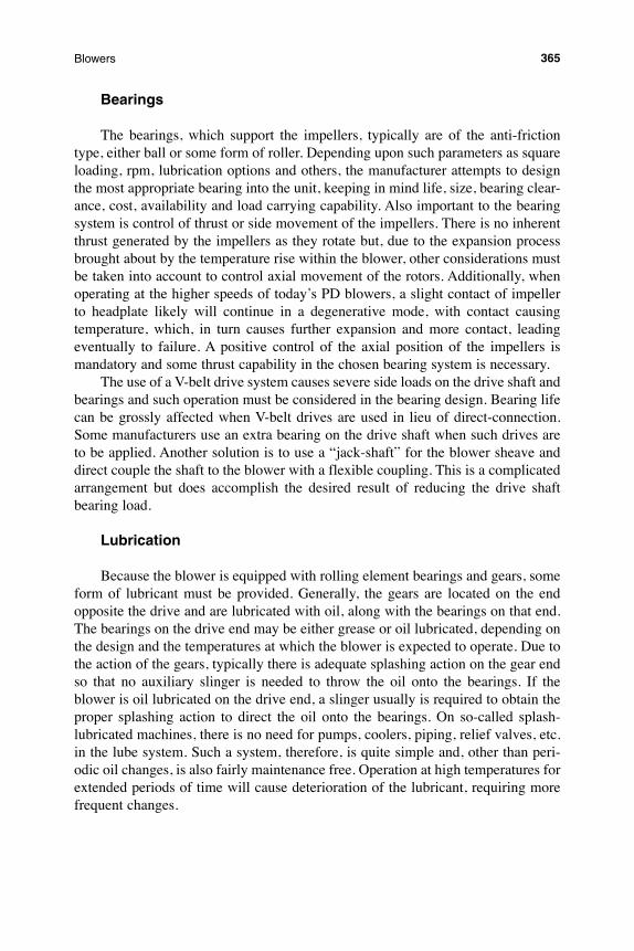
Figure 6.11 Blower Equipped with Splash Lubrication
A pressure lubrication system, while more costly to purchase and maintain, is considered better in the long run as it overcomes the disadvantages of the splash system. It assures that the blower always will be supplied with a cool, clean flow of oil to the critical components. The oil will last longer and the bearings and gears will have a longer life expectancy. A pressure system can be furnished with an oil cooler so that oil temperatures are held to ideal levels, even when the blower is operating at high compression ratios with high ambient temperatures. Safety devices, such as low oil pressure and high oil temperature switches can be supplied. On critical service, where an unplanned shutdown cannot be tolerated, an auto-matic auxiliary oil pump, which comes on at a reduced oil pressure indicating a loss of the main pump, can be fitted into the system.
Figure 6.12 Blower Equipped with Pressure Lubrication
366 Blowers Chap. 6
Casing
The casing, made up of the headplates and cylinder, performs the function of containing the gas and supporting the rotors, while also keeping the entire system in alignment. The materials of construction normally are cast grey iron and the normal design working pressure is 25 psig. With other materials, such as ductile iron, and other designs, the casing pressure rating can be enhanced. Another con-sideration is noise level and it has been demonstrated that the thicker the casing the lower the noise.
timing Gears
Timing gears must be of high quality with good tolerance control to properly maintain the impeller to impeller clearances. A small inaccuracy in the gear profile can bring about contact between the impellers. Poor quality gears also will cause noise, although the gear pitch line velocities are relatively low at about 5000 fpm, maximum. The gear type normally is straight spur, however helical designs are used by some manufacturers. Helical gears produce a definite axial thrust on the rotors and must be considered in the design and life calculations of the bearing system. Most gears today are hardened and ground and of an AGMA quality of 11-12. Several methods are used to attach gears to shafts, but the most common is either some form of taper fit or a dual tapered ring system which, when pulled up axially, places an inward radial force on the gear hub, thus securing it to the shaft. Both methods allow the impellers to be easily “timed” or adjusted in the circum-ferential direction when assembled, or during repair procedures. Older types of attachments utilize radial or axial pins to locate the gears to the shafts with holes drilled and reamed on assembly. This method does not permit more than one or perhaps two repairs before the shafts and gears must be replaced, due to the suc-cessive numbers of holes through the parts.
Timing gears typically are mounted on the end of the blower opposite the drive end to allow easier maintenance and re-timing. However, with the gears mounted on the drive end of the blower, the drive torque is split at the gears prior to being transmitted through the drive rotor, thus improving the torsional characteristics of the rotor. Larger size blowers typically have the timing gears on the drive end.
seals
Sealing systems for air blowers are relatively simple and the air seals usually involve single or multiple labyrinths where the shafts pass through the headplates with the adjacent space being vented to atmosphere. The lubrication seals gener-ally are of the lip type to restrict leakage of the lube oil or grease. The vent area between the air seal (labyrinth) and the lip seal allows the air being handled to bleed to (or from, in the case of vacuum service) the atmosphere, thus keeping the lubricant away from the air being handled. PD blowers, therefore, are considered
367Blowers
to be “oil-free.” This term must be used carefully, as the blower does not remove any hydrocarbons which enter with the inlet air, nor can one guarantee that the unit, under all operating conditions, will not present some trace of oil in the discharged air-stream. It can be stated, for most practical applications, that the PD blower can be considered essentially “oil-free.”
For gases which must be contained within the casing due to their cost or haz-ardous nature, special seals, usually of the mechanical face variety, are used. Some frames require the addition of a pressure lube system to provide cool, clean oil, under pressure, to make the seal function properly. A typical mechanical seal is pressurized by the unit’s pressure lube system. This seal has been found to be very reliable, provided the oil pressure is maintained and the oil is kept cool and clean.
shafts
Shafts, which support the impellers, are of several varieties. Some, especially those which have a lower design square loading, are of steel and are pressed through the impellers and then pinned radially through both parts. The disadvan-tage of this design is that the shaft diameter is restricted, in order to have sufficient material in the narrow, or waist section of the impeller to hold it to the shaft. One alternative is to cast the impeller and shaft in one piece of a stronger material, usu-ally ductile iron, in which case the shaft can be made the full diameter of the waist section of the impeller. This design typically is used on blowers having a design square loading of 25 psi and greater. Another approach is to flange mount a stub shaft to each end of the impeller with high strength bolts and use taper pins for locating purposes. An advantage of this design is that it permits replacement of the shafts without replacing the entire impeller when only the shafts are damaged. The stub shaft design is used for square loading up to about 40 psi.
PeRFoRmaNCe CalCUlatioNs
The process of calculating the performance of a PD blower is relatively simple. Certain facts needed for a blower selection are:
Inlet Pressure (psia)Inlet Temperature (degrees R)Molecular Weight of the Gas Being Handled *Cp/Cv (K value) of the Gas Being Handled **Inlet Volume Requirement (icfm)Discharge Pressure (psia)* If air, calculate, using RH %. Also can use S.G. (MW/28.97; Dry Air = 1.0) ** If dry air, Cp/Cv = 1.395
368 Blowers Chap. 6
slip
The term “slip” is the amount of air that “slips” back from discharge to inlet through the clearances and is expressed in icfm. It is a loss that must be accounted for in the shaft speed required to achieve the specified amount of delivered flow. Slip depends upon the blower inlet conditions and discharge pressure. It also depends upon the clearances within the blower, but for a given size, this parameter is a constant. Each blower model, at any given set of conditions, can be expected to “slip” a certain amount of air back to inlet. In order to calculate for the specific set of conditions where the unit is expected to operate, we start with a known quan-tity and then correct that figure for the actual conditions. The known quantity, established through testing, is called 1 psi slip. This quantity is the rpm at which the blower must operate, with the discharge blocked off, to establish a pressure of 1 psi on a manometer connected to the discharge port. The significance of this is that, with the discharge blocked, all the air coming in at the inlet port is “slipping” back to the inlet. Therefore, since the displacement times the rpm equals the flow rate, and the displacement is constant for a given size, the slip can be expressed in rpm and referred to a standard set of test conditions. The 1 psi slip then can be calculated as follows:
Inlet Pressure = 14.7 psia Inlet Temperature = 68°F (528°R) Inlet S.G. = 1.0 Pressure Differential = 1.0 psi
To correct for actual or specified conditions, the following equation applies:
SLIP = 1 psi SLIP x (ΔP x PS x T1/S.G./P1/TS)1/2
where: 1 psi SLIP = Blower rpm required to provide 1 psi on
air at standard conditions with a blanked discharge.
ΔP = Operating pressure differential in psi. S.G. = Specific Gravity of gas compared to dry
air at 1.0. T1 = Operating inlet temp. in °R (°R = °F + 460) TS = Standard Inlet Temp. (528 °R) P1 = Operating Inlet Press. (psia) PS = Standard Inlet Press. (14.7 psia)
Slip can be reduced if the unit is water injected, as will be discussed later.
369Blowers

inlet Volume/shaft speed
It has been pointed out that the PD blower’s capacity is expressed as displace-ment times rpm. The rpm, as used here, is “effective” rpm, or the actual shaft speed less the slip rpm. The method of calculating either actual rpm for a given inlet flow or flow for a given shaft rpm is shown in this equation:
Q1 = cfr x (rpm - slip) where:
Q1 = Volume Flow of Gas at Blower Inlet in cfm cfr = Blower Displacement in ft3/revolution rpm = Blower Shaft Speed slip = Calculated Slip in rpm
Conversely, for a given flow: Q1 Slip ____ ____
rpm = CFR +
R.PM
Brake Horsepower
As discussed earlier, a PD blower operates on a “Square Card” cycle. The process for calculating the brake horsepower also includes a factor to take friction losses into account. Thus, brake horsepower is a combination of two components:
bhp = ghp + fhp where:
bhp = Brake Horsepower at the Blower Shaft ghp = Gas Horsepower fhp = Friction Horsepower
As explained previously, ghp is calculated as follows:
ghp = K x rpm x ΔP x cfr where:
K = Constant, depending upon pressure or vacuum, gear speed & blower type (from empirically-established curves and approx. = .00436)
rpm = Shaft Speed ΔP = Operating Differential Pressure in psi cfr = Displacement in ft3/revolution
Friction horsepower, fhp, is dependent upon rpm and model/size of blower and is generally a calculated number, using an empirical figure as a starting point, and corrected for rpm or gear speed by some exponent of the ratio of the standard to the
370 Blowers Chap. 6
actual rpm. The actual number is available from curves. If the unit is water injected, a further amount of HP must be added to pump the water.
temperature Rise
Often it is necessary to estimate discharge temperature and sometimes an abso-lute requirement to know delta-T, to insure that the application does not exceed the maximum rating of the blower in question. Following is the equation for this cal-culation, for air service:
ΔT = bhp x T1 x TRF/P1/Q1/.01542 where:
Δ = Temperature Rise in °R (or °F) bhp = Calculated brake horsepower T1 = Inlet temperature in °R TRF = Temperature Rise Factor (Varies by Product Line, Approx. = .90) P1 = Inlet Press. in psia Q1 = Inlet Volume Flow in ft3/min
Modifications in the above are required if the blower is handling a gas other than air or if the unit is water injected.
BloweR PeRFoRmaNCe CHaRaCteRistiCs
The basic characteristic of PD blowers is that they provide a relatively constant inlet volume under variable pressure conditions. These blowers provide high volumetric efficiency and incorporate many design features that contribute to job versatility and economical installation. There are no valves or vanes, reducing maintenance and replacement costs. Completely enclosed construction achieves compactness, provides protection against dust and makes the unit suitable for either indoor or outdoor installations.
Pressure is not developed inside the blower, but by the demand of the system. Discharge pressure, therefore, varies to meet the system’s load conditions of pres-sure vs. flow. Relief valves normally are required to relieve pressure when flow is restricted to the point that the pressure can rise beyond design limits of the blower.
Volume is almost constant with pressure except for a slight increase in slip as the pressure rises. Horsepower is nearly proportional to pressure differential and rpm. At a given pressure differential, the hp is proportional to shaft speed (rpm). At a constant rpm, hp is proportional to pressure differential. Thus, torque varies directly with pressure differential. The unit is defined as a “constant torque” machine for purposes of determining the necessary characteristics for drivers, espe-cially variable speed motors. This is opposite from centrifugal compressors, which
371Blowers
are classified as “variable torque” devices.The characteristics of the PD blower make it ideal for low pressure applica-
tions and vacuum service. It delivers essentially oil-free air and drivers can be sized accurately to the pressure or vacuum requirements.
In two-stage operation, where the discharge flow of one higher displacement machine is directed into the inlet of another, smaller displacement unit, higher pres-sures or lower vacuum levels can be achieved at significant power savings. The application of two-stage blowers normally is a job for the more advanced techni-cian and these selections generally are done at the factory. The basic concept of two-staging is that the actual flow from the first stage must be compressed to a level that can be accepted by the smaller displacement second stage. Until the flow from the first stage is compressed to a flow that the second stage can handle, the pressure continues to rise across the first stage. It is critical that the first stage does not exceed its maximum pressure differential. Therefore, the relative sizes of the two stages are critical. As a vacuum pump, a two-stage blower typically utilizes an inter-stage bypass to allow the excess flow to circumvent the second stage until the compression ratio across the first stage is sufficient to permit the second stage to accept the flow.
seleCtioN PRoCeDURes
There are several methods used to select and determine the performance of a blower for a given set of conditions. These are:
Performance charts Performance curves Computer ProgramsCharts or curves are established from the basic calculations discussed earlier,
using the standard conditions in the process. As the calculation procedure allows for variations in inlet temperature, pressure, S.G., etc., it is the best method to use if accuracy is important. It can be a laborious task. However, computer programs today simplify the process considerably, allowing any number of different sets of conditions to be calculated with ease and rapidity.
This term scfm is used in many customer specifications but often is the source of confusion. scfm means “Standard cubic feet per minute” but must be defined properly since different people use different standards. (The definition of Standard Air (or a Standard atmosphere) adopted by the Compressed Air & Gas Institute, conforming with PNEUROP and ISO standards is:
Pressure = 14.5 psia (1 bar); Temperature = 68 °F (20 °C); Relative Humidity = 0%
ASME has used the definition of Standard air as:
Pressure = 14.7 psia; Temperature = 68 °F; Relative Humidity = 36%
372 Blowers Chap. 6

This gives air having a density of 0.075 lb/ft3. This is the definition for Standard air used in this Section for PD blowers.
To convert from scfm to Inlet, or Actual flow (acfm) the standard and the actual conditions prevailing at the point of measurement, in our case the inlet of the blower, must be known. The equation for this conversion is as follows:
acfm = scfm x {[Ps-(RHs x PVs)] x Ta x Pb} / {[Pb-(RHa x PVa)] * Ts x Pa} where:
Ps = Standard Pressure (psia) Pb = Atmospheric Pressure or Barometer (psia) Pa = Actual Pressure (psia) RHs = Standard Relative Humidity (Expressed as a Decimal) RHa = Actual Relative Humidity (Expressed as a Decimal) PVs = Saturated Vapor Pressure of Water at the Standard
Temperature (psi)* PVa = Saturated Vapor Pressure of Water at the Actual
Temperature (psi)* Ts = Standard Temperature (°R) (°F + 460) Ta = Actual Temperature (°R) *From Steam Tables
Relative Humidity, Temperature, Pressure and Barometer can have a profound effect upon the blower selection, but most importantly, on the horsepower calculated, since the bhp depends on the inlet volume used in the calculation. It is essential that performance data sheets spell out acfm and also provide the actual pressure, temperature and relative humidity conditions at the blower inlet.
Noise/Vibration Control
We have discussed the pulsation characteristic of the PD blower and the fact that the discharge pressure pulse generated causes both noise and vibration. A very effective way to reduce this inherent problem is the use of a wrap-around discharge plenum and a “jet” opening that allows the pressure equalization within the blower to take place in a controlled manner. By controlling the equalization, the internal pressure pulsations are reduced, resulting in less audible “popping” and less shock loading to the bearings and other blower components.
Compared with the conventional PD blower, the jet-assisted unit operates at noise levels up to 5 dB quieter at comparable speeds and pressures. The jet-assisted blower allows higher gear speeds at lower noise levels, permitting selection of smaller size units at comparable noise. In fact, a conventional blower must run at approximately two-thirds the jet-assisted unit speed for a similar noise level.
373Blowers
Obviously the vibration levels also are reduced, and life of bearings, gears and other components is enhanced. Treating piping, silencers and other components with sound absorbing materials helps further.
Gear speed
“Gear Speed” has not yet been addressed in this guide. It is a significant cri-terion, not only in noise considerations but in other rotary blower issues. Gear speed is defined as the velocity of the timing gear at the pitch line diameter of the gear. It is calculated by the following formula:
π ___
GEAR SPEED= 12
x GEAR DIAMETER x rpm
where: GEAR SPEED is in ft/min GEAR DIAMETER is in inches rpm is blower drive shaft speed
The selection of silencers depends upon the blower gear speed as well as other criteria. Gear speed also is a parameter used in the calculation of bhp, in that Friction Horsepower and the Gas Horsepower Factor, discussed earlier under Performance Calculations, require a calculation of gear speed in order to establish these elements.
Further reductions of noise and vibration can be effected by following these guidelines:
Operate at slower rpm (or Gear Speed) Supply a motor rated at 5 dBA less than the final desired noise level Wrap silencers and piping with acoustic material Isolate the blower and baseplate
Complete enclosures, while effective for noise reduction, are sometimes inconvenient from a maintenance standpoint. However, in certain sensitive situa-tions, this may be the only solution.
wateR-sealeD VaCUUm PUmPs
We have noted previously the option of liquid injection to improve a rotary blow-er’s performance. We now will address that subject for vacuum pumps, both single and two-stage.
374 Blowers Chap. 6
GeNeRal
Injection of a liquid into the inlet of the blower performs three functions: 1) Reduces the heat of compression, 2) Partially seals the clearances between the impellers and the casing to reduce slip, and 3) Tends to clean out the internals to help prevent build-up of solids. Another function of liquid injection can be to neu-tralize the effects of an acidic or basic element in the gas stream with the addition of a neutralizing agent into the injected liquid. This is a very special application, however, and requires a very thorough understanding of the chemistry of the situ-ation. We consider this option to be beyond the scope of this chapter, however one should be aware of its possibilities.
The typical injection liquid is water so we will restrict the discussion to water. Even tap water, which is entirely suitable for drinking, will contain certain amounts of chemical compounds, which can precipitate out from the water under certain temperature conditions. Scale typically is calcium carbonate. When water contain-ing significant amounts of calcium carbonate is injected into the blower, given the increase in temperature through the unit, the calcium carbonate can precipitate out and adhere to the internals surfaces, the clearances inside the machine can be eliminated and rubbing can occur. In operation, this soft, wet build-up is generally wiped off as the unit rotates and there is no problem. However, when the system is shut down and the build-up dries out, it expands, becomes hard and adheres more strongly to the blower parts. Given enough time, the unit can be totally locked up and any attempt to start the driver can cause serious damage to the driver, coupling or blower.
Specifications have been developed by blower manufacturers, which spell out the minimum requirements for seal water, including pH, hardness, maximum amounts of various elements, turbidity and other critical concerns.
Many vacuum pump applications are in processes where there can be varying amounts of water already in the gas stream, which will carry over to the vacuum pump. Examples of such applications are vacuum filters and paper machine vacu-um. Although typically there is equipment in the systems, such as separators, to eliminate water carry-over, both for protection of the vacuum pump system and for conservation of the process water, generally there is some water left in the gas. This water also will contain contaminants, which can cause a build-up and must also be dealt with.
In addition to the existence of contaminants in the carry-over liquid, the amount of the carry-over must also be considered. Pumping the seal water requires a certain additional horsepower, which can be calculated. This power is relatively small when the injected amount is within the recommendations for the vacuum pump or blower. When the total amount of injected and carry-over liquid is consid-erable, however, the power to pump the liquid can exceed the capabilities of the driver or another element of the vacuum pump system, including the pump itself. Precautions must be taken to restrict the amount of carry-over liquid, typically with inlet separators. The inlet separator will require a means of draining, since the
375Blowers
separator is under a vacuum. Draining the separator normally is accomplished with either a pump or a “barometric leg” when sufficient height is available to provide the water column necessary to overcome the vacuum level. The ingress of air at such drains must be avoided or the vacuum level will be affected.
The injection liquid must be directed into the vacuum pump so as to disperse within the pump and reach all the internals to do its job. A special nozzle (or sets of nozzles in the largest units) is mounted at the inlet opening of the vacuum pump. This nozzle atomizes the liquid and disperses it to all corners of the internals of the pump. In order to ensure the proper control and cleanliness of the water, a seal water control package will include the following items:
Solenoid valveStrainerFlow meter with bypass valvesFlow switch
The solenoid valve normally is inter-connected with the driver so that the water begins to flow when the driver is started and is turned off when the driver is de-energized. This assures a flow of sealing water during operation. The strainer is to ensure that there is no contaminant in the seal water supply that may clog the flow nozzle or meter. The flow meter is used initially to set the proper amount of water flow into the unit and is recorded in the instruction manual. After setting the appropriate flow, the valves adjacent to the meter are adjusted so that the flow is through the bypass and not through the meter. This is a precaution to protect the flow meter and also to reduce the amount of contaminant build-up inside the meter, which eventually may cause it to be unreadable. The flow switch is interconnected with the driver starter system so that if the flow ceases during operation, the driver will shut down.
It is good practice to operate the machine dry and unloaded for a period of time just prior to shutdown in order to allow the internals to dry out to assist in prevent-ing lock-up during shutdown.
PeRFoRmaNCe CalCUlatioNs
single-stage
The process of determining speeds, horsepowers, etc. for the water-sealed blowers or vacuum pumps is very similar to dry blowers. The differences lie in the calculation of slip, hp and discharge temperature. Gas and friction horsepower (ghp & fhp respectively) are calculated in the same manner as dry units, however an additional amount of hp must be added to allow for pumping the water. Discharge temperature is calculated from compression ratio across the unit and knowledge of the steam tables for purposes of determining the relationship between temperatures and vapor pressures of water at those temperatures.
376 Blowers Chap. 6
slip
Actual inlet flow is calculated in accordance with the manufacturers’ proce-dures, but the process roughly approximates the dry procedures, except for the reduced slip resulting from the water sealing.
Horsepower
The power calculations for a water-sealed unit are identical to the calculations for a dry machine except the power required to pump the water must be considered. Therefore,
bhp = ghp + fhp + whp where:
bhp, ghp and fhp are as previously defined. whp is the power to pump the amount of inlet water at the gear speed of the unit. The value depends on the manufacturer.
Note that whp can be significant. The total flow, including any from the sys-tem, must be considered in this calculation and the user must be cautious about possible overloads due to water flows significantly higher than the normal seal water flow. Such overloads can shut down the driver on high power or, if extreme-ly high, they can damage the pump or other drive train components.
Discharge temperature
Normal calculation of estimated discharge temperature assumes that the inlet and outlet flows are saturated with water vapor. From thermodynamics, at satura-tion the partial pressure of the water in the air stream is equal to the vapor pressure of steam at the temperature of the mixture. Therefore, assuming saturation of the air stream at inlet and discharge, and knowing the saturation pressures of steam from the steam tables, one can calculate the discharge temperature. The partial pressure of the vapor in the inlet gas goes through the same compression as the air from inlet to discharge and some of the seal water evaporates, thus maintaining saturation at the discharge. Therefore, the partial pressure of the vapor on the dis-charge side will be the partial pressure at inlet temperature multiplied by the com-pression ratio of the vacuum pump. The corresponding temperature from the steam tables gives the estimated discharge temperature of the mixture.
VPd = CR x VPi where:
VPd = partial pressure of steam at discharge temperature CR = compression ratio (Pd/Ps in absolute pressures) VPi = partial pressure of steam at inlet temperature
377Blowers
From the steam tables, the discharge temperature of the mixture is the satura-tion temperature at VPd.
The foregoing provides the basics for calculating performance for a water-sealed single-stage rotary vacuum pump. The data sheets, curves, etc. referred to are provided in the manufacturer’s data books for the products in question. In addi-tion, individual performance charts and curves, developed from these procedures are also available for estimating purposes.
two-stage Rotary Blowers and Vacuum Pumps
By arranging two PD blowers in series, the total differential pressure can be increased.
Similarly, vacuum capability can be increased and power requirement decreased with a two-stage arrangement.
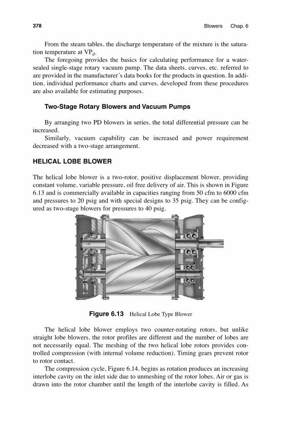
HeliCal loBe BloweR
The helical lobe blower is a two-rotor, positive displacement blower, providing constant volume, variable pressure, oil free delivery of air. This is shown in Figure 6.13 and is commercially available in capacities ranging from 50 cfm to 6000 cfm and pressures to 20 psig and with special designs to 35 psig. They can be config-ured as two-stage blowers for pressures to 40 psig.
Figure 6.13 Helical Lobe Type Blower
The helical lobe blower employs two counter-rotating rotors, but unlike straight lobe blowers, the rotor profiles are different and the number of lobes are not necessarily equal. The meshing of the two helical lobe rotors provides con-trolled compression (with internal volume reduction). Timing gears prevent rotor to rotor contact.
The compression cycle, Figure 6.14, begins as rotation produces an increasing interlobe cavity on the inlet side due to unmeshing of the rotor lobes. Air or gas is drawn into the rotor chamber until the length of the interlobe cavity is filled. As
378 Blowers Chap. 6
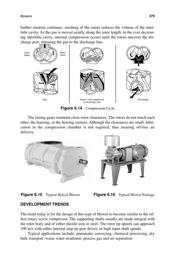
further rotation continues, meshing of the rotors reduces the volume of the inter-lobe cavity. As the gas is moved axially along the rotor length, in the ever decreas-ing interlobe cavity, internal compression occurs until the rotors uncover the dis-charge port, releasing the gas to the discharge line.
Figure 6.14 Compression Cycle
The timing gears maintain close rotor clearances. The rotors do not touch each other, the housing, or the bearing carriers. Although the clearances are small, lubri-cation in the compression chamber is not required, thus insuring oil-free air delivery.
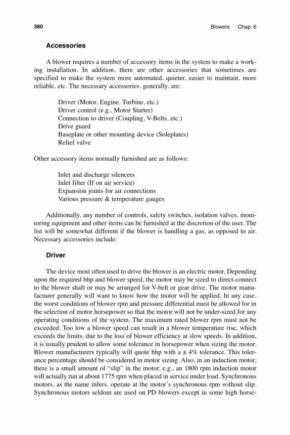
Figure 6.15 Typical Helical Blower Figure 6.16 Typical Blower Package
DeVeloPmeNt tReNDs
The trend today is for the design of this type of blower to become similar to the oil-free rotary screw compressor. The supporting shafts usually are made integral with the rotor body and of either ductile iron or steel. The rotor tip speeds can approach 100 m/s with either internal step-up gear drives, or high input shaft speeds.
Typical applications include: pneumatic conveying, chemical processing, dry bulk transport, waste water treatment, process gas and air separation.
379Blowers
accessories
A blower requires a number of accessory items in the system to make a work-ing installation. In addition, there are other accessories that sometimes are specified to make the system more automated, quieter, easier to maintain, more reliable, etc. The necessary accessories, generally, are:
Driver (Motor, Engine, Turbine, etc.) Driver control (e.g., Motor Starter) Connection to driver (Coupling, V-Belts, etc.) Drive guard Baseplate or other mounting device (Soleplates) Relief valve
Other accessory items normally furnished are as follows:
Inlet and discharge silencers Inlet filter (If on air service) Expansion joints for air connections Various pressure & temperature gauges
Additionally, any number of controls, safety switches, isolation valves, moni-toring equipment and other items can be furnished at the discretion of the user. The list will be somewhat different if the blower is handling a gas, as opposed to air. Necessary accessories include:
Driver
The device most often used to drive the blower is an electric motor. Depending upon the required bhp and blower speed, the motor may be sized to direct-connect to the blower shaft or may be arranged for V-belt or gear drive. The motor manu-facturer generally will want to know how the motor will be applied. In any case, the worst conditions of blower rpm and pressure differential must be allowed for in the selection of motor horsepower so that the motor will not be under-sized for any operating conditions of the system. The maximum rated blower rpm must not be exceeded. Too low a blower speed can result in a blower temperature rise, which exceeds the limits, due to the loss of blower efficiency at slow speeds. In addition, it is usually prudent to allow some tolerance in horsepower when sizing the motor. Blower manufacturers typically will quote bhp with a ± 4% tolerance. This toler-ance percentage should be considered in motor sizing. Also, in an induction motor, there is a small amount of “slip” in the motor, e.g., an 1800 rpm induction motor will actually run at about 1775 rpm when placed in service under load. Synchronous motors, as the name infers, operate at the motor’s synchronous rpm without slip. Synchronous motors seldom are used on PD blowers except in some high horse-
380 Blowers Chap. 6
power, low rpm applications, and where there is a need to adjust the plant’s over-all power factor.
When a variable speed motor is to be used, one must consider the speed range of the system and not operate the unit too slowly due to potential temperature rise. When using a variable speed driver, a torsional analysis may be required to locate the torsional critical speeds so that considerations can be made in the application of the drive system.
The method of starting the blower also should be considered when selecting the motor. Although not recommended, should the blower be required to start up under load, the increased starting torque should be considered in the motor speci-fications. There also are recommended limits for maximum motor torque. Other factors affecting the motor selection, such as voltage, enclosure, insulation, etc. are usually a requirement of the user and are beyond the scope of this discussion.
Other driver choices, such as steam turbines, engines, gas turbines or others may also be considered. Generally, as far as the blower is concerned, the same considerations should be made, as with the motor drive. There are some special concerns with engine drivers, however, especially with respect to the system tor-sional responses. In such cases, a torsional analysis should be performed by the engine manufacturer.
Controls for the driver must be coordinated with, and preferably be supplied by, the vendor of the driver to ensure complete compatibility. The user will likely have some input into the controls selection and there also will be some blower requirements, especially if there are safety devices tied into the driver control.
Driver Connection
Devices to connect the blower to the driver are, for example:
Flexible couplings V-belt Drives Speed-increasing (or decreasing) Gearboxes Universal Joints
When a blower is “direct-coupled” to its driver, the rpm of the driver must not exceed the maximum speed rating of the blower. A “flexible” coupling such as the grid type should always be used to connect the driver and blower shafts. It is extremely important to install the coupling in accordance with the blower and cou-pling manufacturers’ instructions in order to have a successful installation. Some installations require Limited End Float couplings when the unit is driven by a sleeve bearing motor. Always consult the blower manufacturer in these instances. It is very important to carefully level and align the blower/driver when direct-driven, due to the limitations of the coupling regarding mis-alignment.
381Blowers
V-belt Drives
It is not always possible to select a blower that can be economically direct-connected, due to limitations of motor speeds and blower frames available. When this is the case, it is usually convenient to use a V-belt drive and, with the proper selection of sheaves and motor speed, one can come within a few rpm of the blower speed required for the specified blower flow. Use the appropriate service factors as spelled out in the drive manual in order to have a reliable long-lasting system. Installation of the driver is less critical than for direct coupling, but its shaft must be level and parallel with the blower shaft. The driver should be mounted on the inlet side of a vertical blower (horizontal piping) and on the side nearest to the shaft on a horizontal blower. The driver must also be mounted on an adjustable base to permit installing, adjusting and removing the belts. The blower sheave should be no more than 1/8 inch from the blower drive end cover so as to keep the overhang to a minimum. Proper tension is critical and should be accomplished in accordance with the drive manufacturer’s instructions. Excessive tension can cause bearing failures while too little tension can cause slippage and premature belt failure.
Drive Guards
Any type of rotating drive connection should be protected by a stationary guard to prevent injury. OSHA has defined certain standards for drive guards and most blower suppliers furnish their guards in accordance with those standards. Depending upon the installation, one may select a standard or a weather-protected guard.
Blower mounting Device
A fabricated baseplate normally is supplied for mounting of the blower and driver. An option is to mount the units independently on soleplates. In either case, it is recommended that the mounting device be grouted into a concrete foundation. Follow the blower manufacturer’s instructions in that regard. Anchor bolts of the type shown in Figure 6.17 are recommended for tying the soleplates or baseplate into the foundation. Note also, the method of installing the grout, as shown in this figure. Level and alignment are critical and the manufacturer’s instructions should also be followed here. If the unit was shipped from the blower manufacturer mounted on the baseplate along with the driver, it likely was aligned at the factory. However, due to the possibility of the assembly being twisted during shipment, thus disturbing the original alignment, the unit should be checked for alignment and level before starting. The blower instruction book provides the procedure to make these checks.
382 Blowers Chap. 6
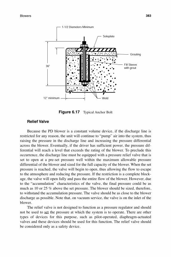
Figure 6.17 Typical Anchor Bolt
Relief Valve
Because the PD blower is a constant volume device, if the discharge line is restricted for any reason, the unit will continue to “pump” air into the system, thus raising the pressure in the discharge line and increasing the pressure differential across the blower. Eventually, if the driver has sufficient power, the pressure dif-ferential will reach a level that exceeds the rating of the blower. To preclude this occurrence, the discharge line must be equipped with a pressure relief valve that is set to open at a pre-set pressure well within the maximum allowable pressure differential of the blower and sized for the full capacity of the blower. When the set pressure is reached, the valve will begin to open, thus allowing the flow to escape to the atmosphere and reducing the pressure. If the restriction is a complete block-age, the valve will open fully and pass the entire flow of the blower. However, due to the “accumulation” characteristics of the valve, the final pressure could be as much as 10 or 25 % above the set pressure. The blower should be sized, therefore, to withstand the accumulation pressure. The valve should be as close to the blower discharge as possible. Note that, on vacuum service, the valve is on the inlet of the blower.
The relief valve is not designed to function as a pressure regulator and should not be used to set the pressure at which the system is to operate. There are other types of devices for this purpose, such as pilot-operated, diaphragm-actuated valves and these devices should be used for this function. The relief valve should be considered only as a safety device.
383Blowers
other accessories
In addition to the above accessories considered as necessary for the successful, safe operation of the blower system, the following may be considered desirable for convenience, safety and/or comfort.
inlet and Discharge silencers
We have discussed the noise characteristics of the PD blower and the ways to reduce the level. The most popular method is by use of silencers or mufflers. Nearly every blower installation has at least an inlet or a discharge silencer as a part of the package. There are several different styles and models of silencers and they are selected based upon the following criteria:
Blower Capacity Blower Discharge Pressure * Blower Speed and Type* Or inlet vacuum in case of a vacuum pump
There are four basic silencer types:• Absorption - unimpeded flow passage lined with acoustical material
behind a perforated annulus. • Chamber - internal baffles forming two or three unlined chambers inter-
connected by perforated tubes, tuned to subdue flow pulsations. • Combination - internal baffles forming unlined chambers inter-connected
by perforated tubes with extended acoustically packed sound absorbing section.
• Silencer/Separator- chamber type silencer with drain allowing 95% water removal from the air stream.
It has been found that the blower gear speed has an influence on the silencer selection. Generally, at gear speeds below 3300 ft./min for the inlet silencer and 2700 ft./min for the discharge silencer selection, a chamber type is satisfactory. Above those speeds, it is necessary to add an acoustical packed section or use the combination type silencer, which has the pack built in. The packing absorbs the higher frequencies, which tend to cause ringing of the silencer shell and/or piping. In any case, the silencers should be mounted as close to the blower as possible, with the acoustical pack section closest to the connection of the blower.
The selection charts are relatively simple to use, knowing the gear speed, flow and pressure. Each manufacturer publishes its own list of the various types, so the first thing to do, after determining the gear speed, is to select the type. Next, enter the chart for inlet size selection with the inlet volume of the blower. Read directly the inlet silencer size. The discharge silencer size is also based on the inlet volume, but the discharge pressure is also a parameter. Find a silencer size, which will handle the blower inlet volume at the operating pressure.
384 Blowers Chap. 6
Sizing a silencer for vacuum service is similar, except the inlet silencer usually is not required.
Silencers are available with different connection configurations to fit various piping arrangements. Select the straight-through or other configuration, which best fits the piping system design.
Typically, gas pumps are equipped with only discharge silencers as the inlet is usually piped to a system and does not cause noise problems.
inlet Filter
There are several reasons to use an inlet filter on a pressure blower air application. Often, it is important to keep foreign material out of the system down-stream of the blower, due to the system’s inability to handle contaminants. An example is the fine bubble diffusers utilized in wastewater treatment plants. These diffusers, often made of porous ceramic material, are subject to clogging and must be protected from foreign material. There are other considerations, such as clog-ging of instrumentation, contamination of product, erosion of various parts of the blower system, build-up on valves and other parts, etc.
Industrial dry-type filters are recommended on PD blowers. The filter medium should be rated, as a minimum, 90% efficient on 10 micron particles and larger. However, 99% efficiency is very easy to achieve with dry-type filters.
Intake filters are sized according to the face velocity across the filter medium. The higher the face velocity, the faster the medium will load and require cleaning. Therefore, ratings of dry-type filters are on the basis of differential pressure across the filter, and vary according to manufacturers, but are approximately 1/2 - 1" H2O when clean. As the filter medium becomes loaded with dust or dirt, pressure drop across the filter is increased, causing a lower inlet pressure to the blower, resulting in increased pressure differential across the blower and a drop in capacity. A manometer or differential pressure gauge should be placed across the filter to deter-mine when the filter should be cleaned or replaced.
Weather hoods are available to keep rain, snow and other foreign particles away from the filter element.
Sizing of inlet filters is relatively simple and is similar to inlet silencers. The only information required for filters mounted on the blower, is the inlet volume of the blower. Should air be drawn from outside in an industrial atmosphere, where there is a risk of heavier contamination, a heavy duty inlet filter should be consid-ered.
Inlet filter-silencers also are available but in general, they do not do as good a job of silencing.
385Blowers
expansion Joints
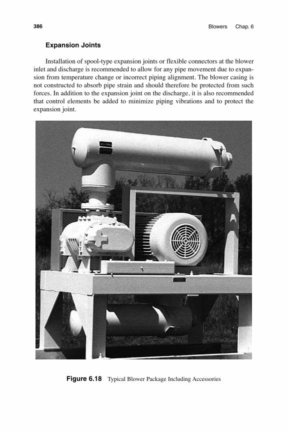
Installation of spool-type expansion joints or flexible connectors at the blower inlet and discharge is recommended to allow for any pipe movement due to expan-sion from temperature change or incorrect piping alignment. The blower casing is not constructed to absorb pipe strain and should therefore be protected from such forces. In addition to the expansion joint on the discharge, it is also recommended that control elements be added to minimize piping vibrations and to protect the expansion joint.
Figure 6.18 Typical Blower Package Including Accessories
386 Blowers Chap. 6