Embed Size (px)
Citation preview
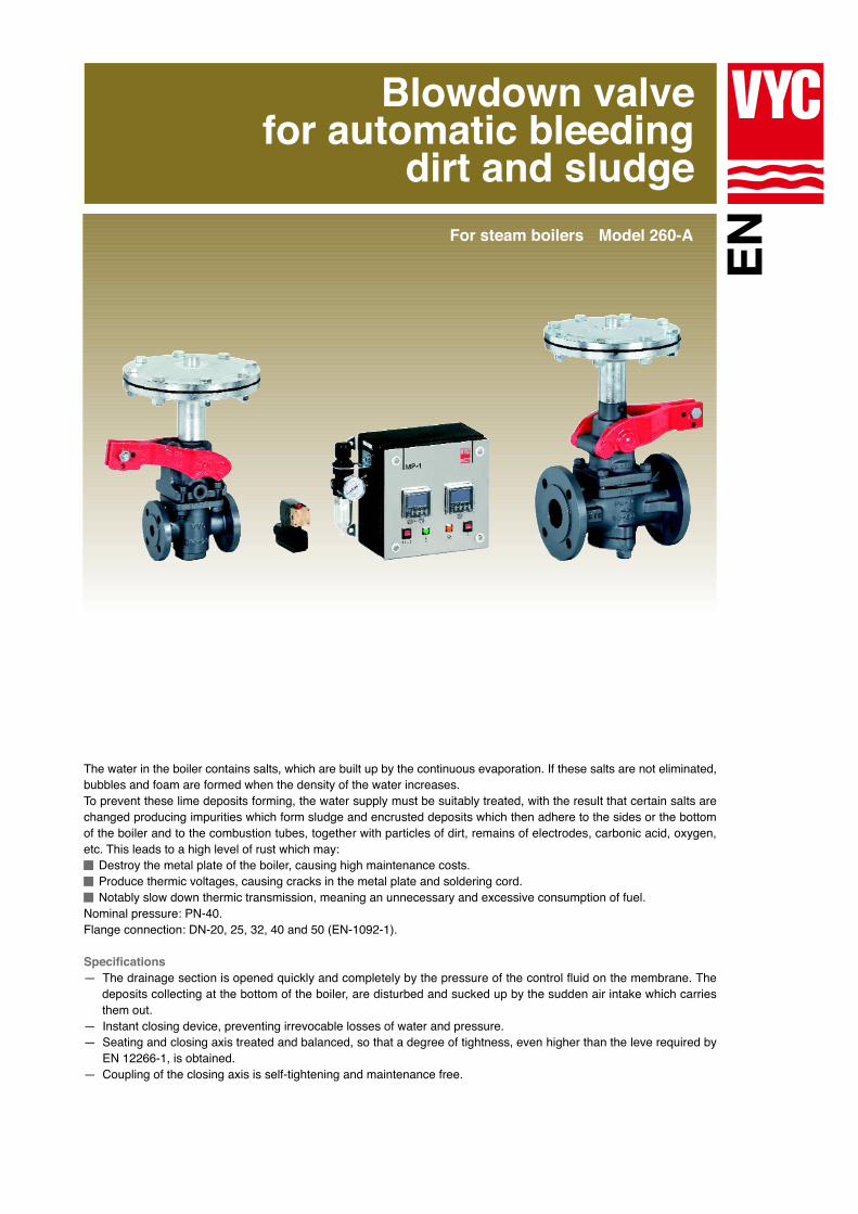
Blowdown valvefor automatic bleeding
dirt and sludgeModel 260-AFor steam boilers
The water in the boiler contains salts, which are built up by the continuous evaporation. If these salts are not eliminated,bubbles and foam are formed when the density of the water increases.To prevent these lime deposits forming, the water supply must be suitably treated, with the result that certain salts arechanged producing impurities which form sludge and encrusted deposits which then adhere to the sides or the bottomof the boiler and to the combustion tubes, together with particles of dirt, remains of electrodes, carbonic acid, oxygen,etc. This leads to a high level of rust which may:
Destroy the metal plate of the boiler, causing high maintenance costs.Produce thermic voltages, causing cracks in the metal plate and soldering cord.Notably slow down thermic transmission, meaning an unnecessary and excessive consumption of fuel.
Nominal pressure: PN-40.Flange connection: DN-20, 25, 32, 40 and 50 (EN-1092-1).
Specifications—aThe drainage section is opened quickly and completely by the pressure of the control fluid on the membrane. The deposits collecting at the bottom of the boiler, are disturbed and sucked up by the sudden air intake which carries them out.—aInstant closing device, preventing irrevocable losses of water and pressure.—aSeating and closing axis treated and balanced, so that a degree of tightness, even higher than the leve required by—aEN 12266-1, is obtained.—aCoupling of the closing axis is self-tightening and maintenance free.
Efficiency and EmptyingBleeding processes should coincide as far as possible with momentswhen the water is at rest or at minimum steam extraction, so that thedeposits are collected at the bottom of the boiler.
Carry out bleeding process at least every 8 hours. The effective durationis estimated to be 3 ÷ 4 seconds although we recommend you keep tothe following mathematical model:
To establish the salinity of the water, the quantity of salts extracted perunit of time must be equal to that of the water supply in this same period.Which can be expressed:
M . A = S . PWhere:Q = Real steam production of the boiler. (Kg/h).A = Water supply. (l/h).M = Salinity of the water supply. (mg/l).P = Water extracted in the bleeding process. (l/h).S = Desired salinity inside the boiler. (mg/l).S = Specific mass of water inside the boiler. (Kg/l).p = Working pressure. (bar).
Example:Q = 1.520 Kg/h.M = 200 mg/l.S = 4.000 mg/l.S = 1 Kg/l.p = 3 bar.
The water to be bled compared to the steam produced is:
P = . QM(S-M) . S
P = 80 l/h.
C = 8 l/s.
For the DN the volume (C) in l/s can be calculatedas shown in the diagram.
The quotient (P/C) tells us the intervals betweenbleeding processes and the duration of them (T) inseconds per hour.
Boiler pressure in bar
25 to 50
40
35
200
Compressed air
4 ÷ 7
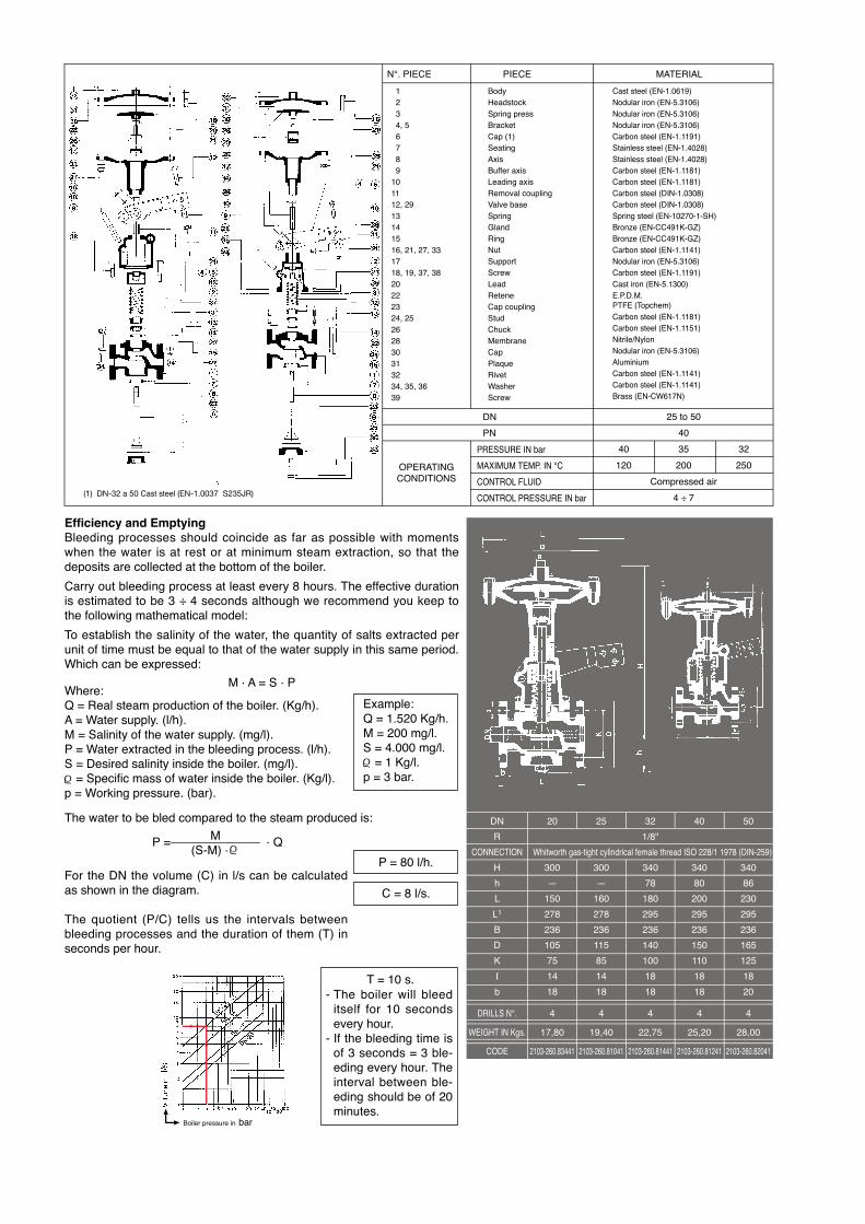
N°. PIECE PIECE MATERIAL
01020304, 506070809101112, 2913141516, 21, 27, 331718, 19, 37, 3820222324, 25262830313234, 35, 3639
BodyHeadstockSpring pressBracketCap (1)SeatingAxisBuffer axisLeading axisRemoval couplingValve baseSpringGlandRingNutSupportScrewLeadReteneCap couplingStudChuckMembraneCapPlaqueRivetWasherScrew
Cast steel (EN-1.0619)Nodular iron (EN-5.3106)Nodular iron (EN-5.3106)Nodular iron (EN-5.3106)Carbon steel (EN-1.1191)Stainless steel (EN-1.4028)Stainless steel (EN-1.4028)Carbon steel (EN-1.1181)Carbon steel (EN-1.1181)Carbon steel (DIN-1.0308)Carbon steel (DIN-1.0308)Spring steel (EN-10270-1-SH)Bronze (EN-CC491K-GZ)Bronze (EN-CC491K-GZ)Carbon steel (EN-1.1141)Nodular iron (EN-5.3106)Carbon steel (EN-1.1191)Cast iron (EN-5.1300)E.P.D.M.PTFE (Topchem)Carbon steel (EN-1.1181)Carbon steel (EN-1.1151)Nitrile/NylonNodular iron (EN-5.3106)AluminiumCarbon steel (EN-1.1141)Carbon steel (EN-1.1141)Brass (EN-CW617N)
DN
PN
PRESSURE IN bar
MAXIMUM TEMP. IN °C
CONTROL FLUID
CONTROL PRESSURE IN bar
OPERATINGCONDITIONS
32
250
40
120
DN
R
CONNECTION
H
h
L
L1
B
D
K
Ι
b
DRILLS N°.
WEIGHT IN Kgs.
CODE
4
17,80
2103-260.83441
20
300
—
150
278
236
105
75
14
18
25
300
—
160
278
236
115
85
14
18
32
1/8"
340
78
180
295
236
140
100
18
18
40
340
80
200
295
236
150
110
18
18
50
340
86
230
295
236
165
125
18
20
4
19,40
2103-260.81041
4
22,75
2103-260.81441
4
25,20
2103-260.81241
4
28,00
2103-260.82041
Whitworth gas-tight cylindrical female thread ISO 228/1 1978 (DIN-259)
T = 10 s.The boiler will bleeditself for 10 secondsevery hour.If the bleeding time isof 3 seconds = 3 ble-eding every hour. Theinterval between ble-eding should be of 20minutes.
-
-
(1) DN-32 a 50 Cast steel (EN-1.0037 S235JR)
MP-1
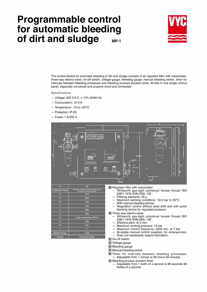
Programmable controlfor automatic bleedingof dirt and sludge
Programmable controlfor automatic bleedingof dirt and sludge MP-1
INLET
INTERVAL BETWEENBLEEDING PROCESSES
BLEEDING PROCESS DURATION
ON/OFFVOLTAGE BLEEDING
MANUAL BLEEDING
CONTROL
DISCHARGE
Specifications
— Voltage: 220 V.A.C. ± 10% 50/60 Hz.
— Consumption: 10 V.A.
— Temperature: -10 to +55°C.
— Protection: IP-50.
— Fuses: 1 A/250 V.
The control device for automatic bleeding of dirt and sludge consists of air regulator filter with manometer,three-way electro-valve, on-off switch, voltage gauge, bleeding gauge, manual bleeding switch, timer forintervals between bleeding processes and bleeding process duration timer. All this in one single controlpanel, especially conceived and properly wired and connected.
Regulator filter with manometer:—aWhitworth gas-tight cylindrical female thread ISO—a228/1 1978 (DIN-259): 1/8".—aFiltering elements: 25 μ.—aMaximum working conditions: 10,5 bar to 50°C. .—aWith manual bleeding device.—aRegulation control without axial shift and with quick—ablocking device for regulated pressure.Three-way electro-valve:—aWhitworth gas-tight cylindrical female thread ISO—a228/1 1978 (DIN-259): 1/8".—aEffective pitch: Ø 2 mm.—aMaximum working pressure: 10 bar.—aMaximum control frequency: 2000 min. at 7 bar. .—aBi-stable manual control supplies, for emergencies.—aDoes not necessarily require lubrication.On-off switch.Voltage gauge.Bleeding gauge.Manual bleeding switch.Timer for intervals between bleeding processes:—aAdjustable from 1 minute to 99 hours 59 minutes. .Bleeding process duration timer:—aAdjustable from 1 tenth of a second to 99 seconds 99—atenths of a second.
1
2
34567
R
CONNECTION
H
H1
H2
F
L
L1
D
K1
K2
Ι
WEIGHT IN Kgs.
CODE
1/8"
218
200
150
152
280
200
Tube connection Ø 6/4
220
161
7
4,56
2103-260.0000
Whitworth gas-tight cylindrical female threadISO 228/1 de 1978 (DIN-295)
8
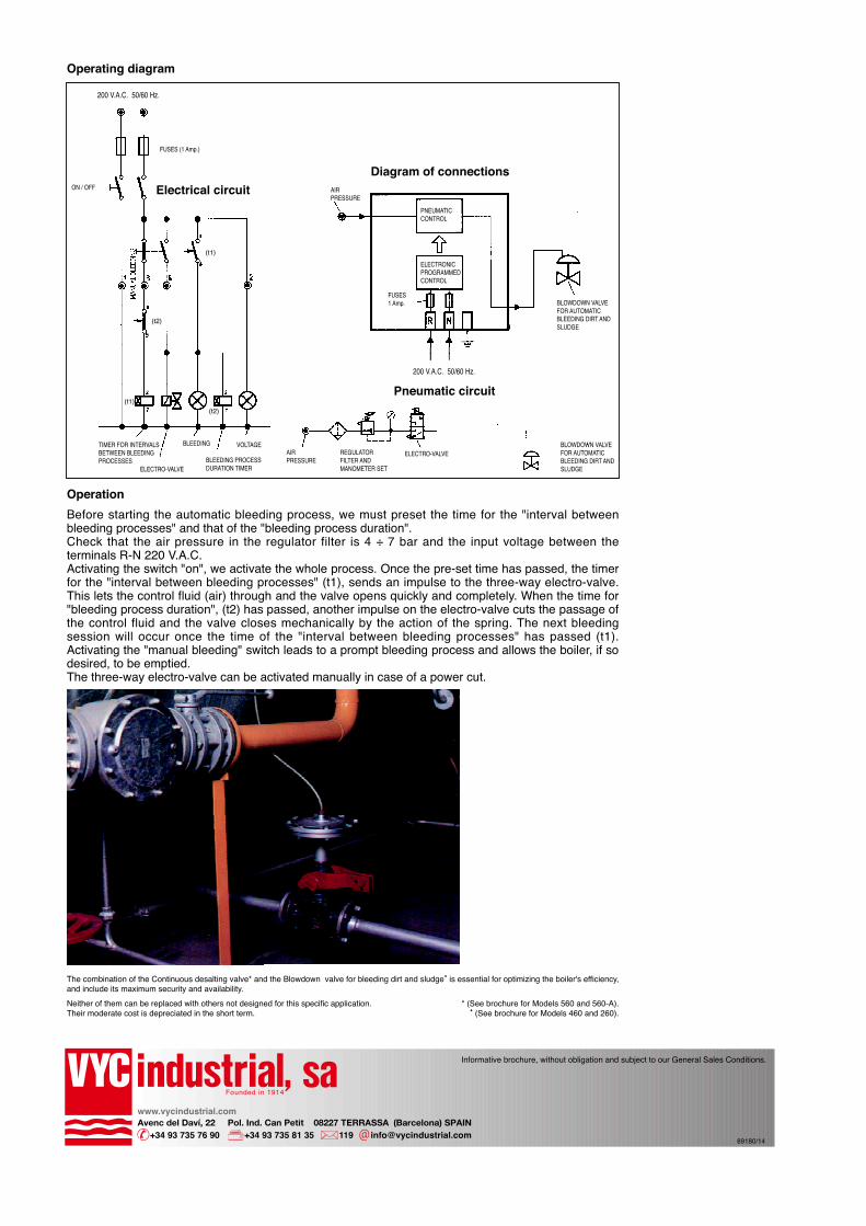
Operating diagram
Electrical circuit
200 V.A.C. 50/60 Hz.
FUSES (1 Amp.)
ON / OFF
TIMER FOR INTERVALSBETWEEN BLEEDINGPROCESSES
ELECTRO-VALVE
BLEEDING
BLEEDING PROCESSDURATION TIMER
VOLTAGEAIRPRESSURE
REGULATORFILTER ANDMANOMETER SET
ELECTRO-VALVEBLOWDOWN VALVEFOR AUTOMATICBLEEDING DIRT ANDSLUDGE
BLOWDOWN VALVEFOR AUTOMATICBLEEDING DIRT ANDSLUDGE
Pneumatic circuit
Diagram of connectionsAIRPRESSURE
PNEUMATICCONTROL
ELECTRONICPROGRAMMEDCONTROL
FUSES1 Amp.
200 V.A.C. 50/60 Hz.
Operation
Before starting the automatic bleeding process, we must preset the time for the "interval betweenbleeding processes" and that of the "bleeding process duration".Check that the air pressure in the regulator filter is 4 ÷ 7 bar and the input voltage between theterminals R-N 220 V.A.C.Activating the switch "on", we activate the whole process. Once the pre-set time has passed, the timerfor the "interval between bleeding processes" (t1), sends an impulse to the three-way electro-valve.This lets the control fluid (air) through and the valve opens quickly and completely. When the time for"bleeding process duration", (t2) has passed, another impulse on the electro-valve cuts the passage ofthe control fluid and the valve closes mechanically by the action of the spring. The next bleedingsession will occur once the time of the "interval between bleeding processes" has passed (t1).Activating the "manual bleeding" switch leads to a prompt bleeding process and allows the boiler, if sodesired, to be emptied.The three-way electro-valve can be activated manually in case of a power cut.
The combination of the Continuous desalting valve* and the Blowdown valve for bleeding dirt and sludge• is essential for optimizing the boiler's efficiency,and include its maximum security and availability.
Neither of them can be replaced with others not designed for this specific application.Their moderate cost is depreciated in the short term.
* (See brochure for Models 560 and 560-A).• (See brochure for Models 460 and 260).
(t1)
(t1)(t2)
(t2)
Informative brochure, without obligation and subject to our General Sales Conditions.
89180/14
Founded in 1914
www.vycindustrial.comAvenc del Daví, 22 Pol. Ind. Can Petit 08227 TERRASSA (Barcelona) SPAIN +34 93 735 76 90 +34 93 735 81 35 119 [email protected]