Embed Size (px)
Citation preview
IOSR Journal of Mechanical and Civil Engineering (IOSR-JMCE)
e-ISSN: 2278-1684,p-ISSN: 2320-334X, Volume 8, Issue 1 (Jul. - Aug. 2013), PP 12-21 www.iosrjournals.org
www.iosrjournals.org 12 | Page
Blow Mould Tool Design and Manufacturing Process for 1litre
Pet Bottle
K. GiridharReddy, K. Rajagopal M.Tech, Ph.D M. Tech Student, Dept of Mechanical Engineering, K.S.R.M College of Engg, Kadapa, A.P
(Professor, Dept of Mechanical Engineering, K.S.R.M College of Engg, Kadapa, Andhra Pradesh, India)
Abstract: the concepts of Blow molding is a process used to produce hollow objects from thermoplastic. The
basic blow molding process has two fundamental phases. First, a parson (or a perform) of hot plastic resin in a
somewhat tubular shape is created. Second, compressed air is used to expand the hot perform and press it
against mould cavities. The pressure is held until the plastic cools. Blow molding process is used for which has
thin wall sections.In this thesis, blow mould design is to be done for a bottle having 0.5mm thickness. This
thickness cannot be filled in pressure injection molding. So blow molding is considered for pet bottle design.
The mould is prepared by first modeling the part, extracting core & cavity and generating CNC program. Blow
mould tool design is done in Pro/Engineer according to HASCO standards. A prototype of the pet bottle using
blow mould design is also included.
I. Introduction 1.1 Bottle A bottle is a rigid container with a neck that is narrower than the body and a "mouth.Bottles are often
made of glass, clay, plastic, aluminum or other impervious materials, and typically used to store liquids such as
water, milk, soft drinks, ink, chemicals and etc. A device applied in the bottling line to seal the mouth of a
bottle is termed an external bottle cap,.
The bottle has developed over millennia of use, with some of the earliest examples appearing in China,
Phoenicia, Rome and Crete. Bottles are often recycled according to the SPI recycling code for the material.
Some regions have a legally mandated deposit which is refunded after returning the bottle to the retailer.
1.2 Plastic Bottle
Plastic bottles range from very small sample bottles to large carboys. The plastic is strain oriented in
the stretch blow molding manufacturing process.
II. Hollow Plastic Molds And Molding Type 2.1 Injection Molding
When it comes to Injection Molding, the melted plastic will be forced into special mold cavities. When
they cool down, the mold is removed. In plastic injection molding, heated plastic and is fed into the mold,
which forms into the part as it cools
2.2 Blow Molding
This process is pretty much comparable with injection molding but the only difference is that, in this case, heated liquid plastic vertically pours out of barrel-like pot into molten tubes., the vacuum part is created.
Most bottles, tubes or containers are formed with this type of molding. Hot plastic resin is combined with a
pressurized gas to fill and press the mold cavity, forming a hollow part.
2.3 Compression Molding
This process also deals with plastic mold processes, but it involves pressing of solid plastic slugs
between highly hot mold halves. Thus the parts created air-cooled afterwards. This molding process can also
result in "flash lines" of extra plastic, like with regular injection molding.
2.4 .Film Insert Molding
This molding technique literally imbeds images underneath the exterior of molded parts. At this point,
materials akin to film or fabric will be slotted into the mold. Then plastic will be injected.
Blow Mould Tool Design And Manufacturing Process For 1litre Pet Bottle
www.iosrjournals.org 13 | Page
III. About Blow Moulding Blow molding process principle comes from the idea of blowing glass. This blow molding was
introduced in the year of 1937.
3.1 Types Of Blow Molding
*Extrusion blow molding
*Continuous extrusion
*Injection blow molding
*stretch blow molding
*Inttermitent extrusion
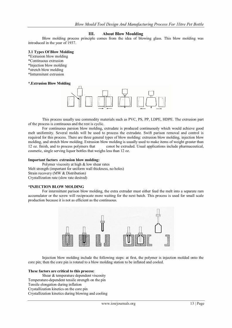
*.Extrusion Blow Molding
This process usually use commodity materials such as PVC, PS, PP, LDPE, HDPE. The extrusion part
of the process is continuous and the rest is cyclic.
For continuous parsion blow molding, extrudate is produced continuously which would achieve good
melt uniformity. Several molds will be used to process the extrudate. Swift parison removal and control is
required for this process. There are three general types of blow molding: extrusion blow molding, injection blow
molding, and stretch blow molding. Extrusion blow molding is usually used to make items of weight greater than
12 oz. finish, and to process polymers that conot be extruded. Usual applications include pharmaceutical,
cosmetic, single serving liquor bottles that weighs less than 12 oz.
Important factors extrusion blow molding:
Polymer viscosity at high & low shear rates Melt strength (important for uniform wall thickness, no holes)
Strain recovery (MW & Distribution)
Crystallization rate (slow rate desired)
*INJECTION BLOW MOLDING
For intermittent parison blow molding, the extra extruder must either feed the melt into a separate ram
accumulator or the screw will reciprocate more waiting for the next batch. This process is used for small scale
production because it is not as efficient as the continuous.
Injection blow molding include the following steps: at first, the polymer is injection molded onto the
core pin; then the core pin is rotated to a blow molding station to be inflated and cooled.
These factors are critical to this process:
Shear & temperature dependent viscosity
Temperature-dependent tensile strength on the pin
Tensile elongation during inflation
Crystallization kinetics on the core pin
Crystallization kinetics during blowing and cooling
Blow Mould Tool Design And Manufacturing Process For 1litre Pet Bottle
www.iosrjournals.org 14 | Page
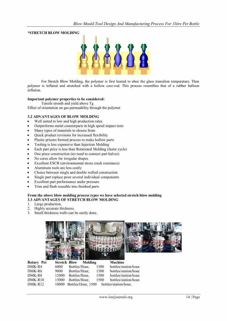
*STRETCH BLOW MOLDING
For Stretch Blow Molding, the polymer is first heated to aboe the glass transition temperature. Then
polymer is inflated and stretched with a hollow core-rod. This process resembles that of a rubber balloon
inflation.
Important polymer properties to be considered:
Tensile strenth and yield above Tg
Effect of orientation on gas permeability through the polymer
3.2 ADVANTAGES OF BLOW MOLDING
Well suited to low and high production rates
Outperforms metal counterparts in high speed impact tests
Many types of materials to choose from
Quick product revisions for increased flexibility
Plastic prisons formed process to make hollow parts
Tooling is less expensive than Injection Molding
Each part price is less than Rotational Molding (faster cycle)
One piece construction (no need to connect part halves)
No cores allow for irregular shapes
Excellent ESCR (environmental stress crack resistance)
Aluminum tools are less costly
Choice between single and double walled construction
Single part replace prior several individual components
Excellent part performance under pressure
Trim and flash reusable into finished parts
From the above blow molding process types we have selected stretch blow molding
3.3 ADVANTAGES OF STRETCH BLOW MOLDING
1. Large production.
2. Highly accurate thickness.
3. Small thickness walls can be easily done.
Rotary Pet Stretch Blow Molding Machine DMK-R4 6000 Bottles/Hour, 1500 bottles/station/hour.
DMK-R6 9000 Bottles/Hour, 1500 bottles/station/hour.
DMK-R8 12000 Bottles/Hour, 1500 bottles/station/hour.
DMK-R10 15000 Bottles/Hour, 1500 bottles/station/hour.
DMK-R12 18000 Bottles/Hour, 1500 bottles/station/hour.
Blow Mould Tool Design And Manufacturing Process For 1litre Pet Bottle
www.iosrjournals.org 15 | Page
IV. Introduction To Cad Computer-aided design (CAD), also known as computer-aided design and drafting (CADD), is the
use of computer technology for the process of design and design-documentation. Computer Aided Drafting
describes the process of drafting with a computer. CADD software, or environments, provide the user with
input-tools for the purpose of streamlining design processes; drafting, documentation, and manufacturing
processes. CADD output is often in the form of electronic files for print or machining operations.
CADD environments often involve more than just shapes. As in the manual drafting of technical and
engineering drawings, the output of CAD must convey information, such as materials, processes, dimensions,
and tolerances, according to application-specific conventions.
CAD may be used to design curves and figures in two-dimensional (2D) space; or curves, surfaces, and
solids in three-dimensional (3D) objects.The modern ubiquity and power of computers means that even perfume
bottles and shampoo dispensers are designed using techniques unheard of by engineers of the 1960s. CAD has been a major driving force for research in computational geometry, computer graphics (both hardware and
software), and discrete differential geometry.
The design of geometric models for object shapes, in particular, is often called computer-aided geometric
design (CAGD).
Current computer-aided design software packages range from 2D vector-based drafting systems to 3D
solid and surface modellersSome CAD software is capable of dynamic mathematic modeling, in which case it
may be marketed as CADD — computer-aided design and drafting.
4.1 Types of CAD Software
2D CAD
Two-dimensional, or 2D, CAD is used to create flat drawings of products and structures. Objects created in 2D CAD are made up of lines, circles, ovals, slots and curves. 2D CAD programs usually include a
library of geometric images; the ability to create Bezier curves, splines and polylines; Among the most popular
2D CAD programs are AutoCAD, CADkey, CADDS 5, and Medusa.
3D CAD
Three-dimensional (3D) CAD programs come in a wide variety of types, intended for different
applications and levels of detail. Some 3D CAD programs include Autodesk Inventor, CoCreate Solid Designer,
Pro/Engineer SolidEdge, SolidWorks, Unigraphics NX and VX CAD, CATIA V5.
3D Wireframe and Surface Modeling
CAD programs that feature 3D wireframe and surface modeling create a skeleton-like inner structure of the
object being modeled. A surface is added on later. These types of CAD models are difficult to translate into
other software and are therefore rarely used anymore.
Solid Modeling
Solid modeling in general is useful because the program is often able to calculate the dimensionsof the
object it is creating. Many sub-types of this exist. Constructive Solid Geometry (CSG) CAD uses the same basic
logic as 2D CAD
V. Introduction To Pro/Engineer Pro/ENGINEER is a feature based, parametric solid modeling program. As such, it's use is
significantly different from conventional drafting programs. In conventional drafting (either manual or computer assisted), various views of a part are created in an attempt to describe the geometry. Each view
incorporates aspects of various features (surfaces, cuts, radii, holes, protrusions) but the features are not
individually defined. In feature based modeling, each feature is individually described then integrated into the
part
An SLA file to a rapid prototyping system (stereolithography, etc.), use of the SLA part in hands-on
verification of fit, form, and function, and then export of an IGES file to the molder or toolmaker.
Different Modules In Pro/Engineer *PART DESIGN
*ASSEMBLY
*DRAWING
*SHEETMETAL
*MOULD DESIGN
*MANUFACTURING
Blow Mould Tool Design And Manufacturing Process For 1litre Pet Bottle
www.iosrjournals.org 16 | Page
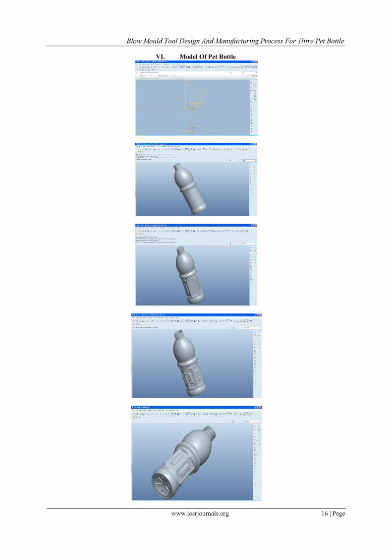
VI. Model Of Pet Bottle
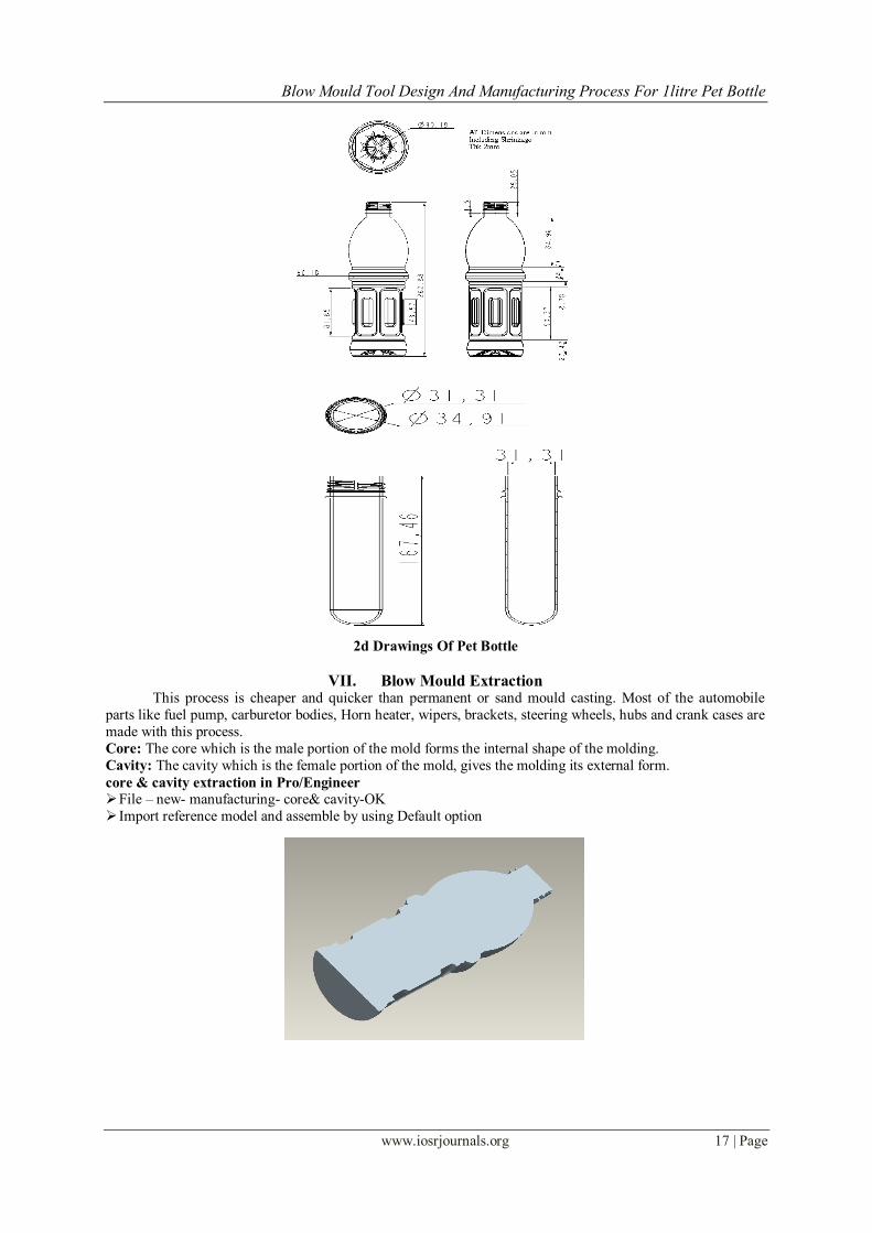
Blow Mould Tool Design And Manufacturing Process For 1litre Pet Bottle
www.iosrjournals.org 17 | Page
2d Drawings Of Pet Bottle
VII. Blow Mould Extraction This process is cheaper and quicker than permanent or sand mould casting. Most of the automobile
parts like fuel pump, carburetor bodies, Horn heater, wipers, brackets, steering wheels, hubs and crank cases are
made with this process.
Core: The core which is the male portion of the mold forms the internal shape of the molding.
Cavity: The cavity which is the female portion of the mold, gives the molding its external form.
core & cavity extraction in Pro/Engineer
File – new- manufacturing- core& cavity-OK
Import reference model and assemble by using Default option
Blow Mould Tool Design And Manufacturing Process For 1litre Pet Bottle
www.iosrjournals.org 18 | Page
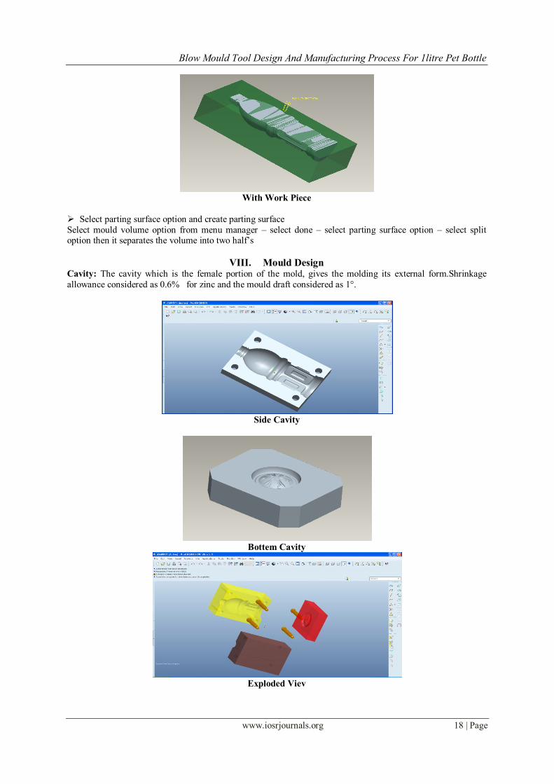
With Work Piece
Select parting surface option and create parting surface
Select mould volume option from menu manager – select done – select parting surface option – select split option then it separates the volume into two half’s
VIII. Mould Design Cavity: The cavity which is the female portion of the mold, gives the molding its external form.Shrinkage
allowance considered as 0.6% for zinc and the mould draft considered as 1°.
Side Cavity
Bottem Cavity
Exploded Viev
Blow Mould Tool Design And Manufacturing Process For 1litre Pet Bottle
www.iosrjournals.org 19 | Page
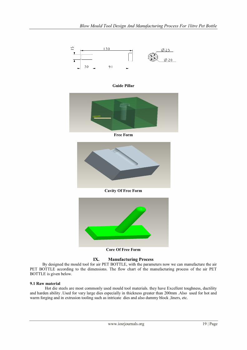
Guide Pillar
Free Form
Cavity Of Free Form
Core Of Free Form
IX. Manufacturing Process By designed the mould tool for air PET BOTTLE, with the parameters now we can manufacture the air
PET BOTTLE according to the dimensions. The flow chart of the manufacturing process of the air PET
BOTTLE is given below.
9.1 Raw material
Hot die steels are most commonly used mould tool materials. they have Excellent toughness, ductility
and harden ability .Used for vary large dies especially in thickness greater than 200mm .Also used for hot and warm forging and in extrusion tooling such as intricate dies and also dummy block ,liners, etc.
Blow Mould Tool Design And Manufacturing Process For 1litre Pet Bottle
www.iosrjournals.org 20 | Page
9.2 Surface grinding
After selecting raw material surface grinding is done, Surface Grinding is a widely used process of
machining in which a spinning wheel covered in rough particles cuts chips of metallic or non metallic substance making them flat or smooth.
9.3 CNC machining
In modern CNC systems, end-to-end component design is highly automated using CAD/CAM
programs. The programs produce a computer file that is interpreted to extract the commands needed to operate a
particular machine, and then loaded into the CNC machines for production. Since any particular component
might require the use of a number of different tools - drills, saws, etc.
9.4 Heat treatment
To increase the strength of the material it is heat treated. Heat treatment is an important operation in
the manufacturing process of machine parts and tools. Heat Treatment is the controlled heating and cooling of metals to alter their physical and mechanical properties without changing the product shape.
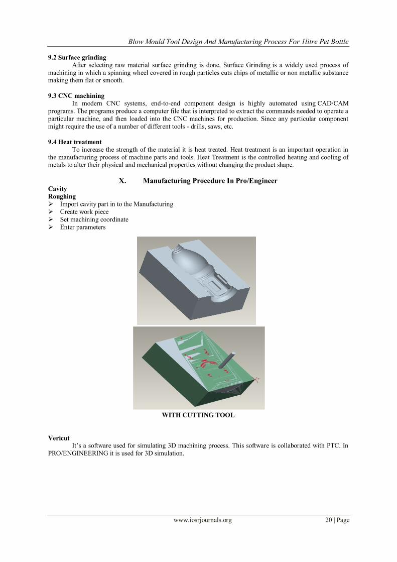
X. Manufacturing Procedure In Pro/Engineer Cavity
Roughing
Import cavity part in to the Manufacturing
Create work piece
Set machining coordinate
Enter parameters
WITH CUTTING TOOL
Vericut It’s a software used for simulating 3D machining process. This software is collaborated with PTC. In
PRO/ENGINEERING it is used for 3D simulation.
Blow Mould Tool Design And Manufacturing Process For 1litre Pet Bottle
www.iosrjournals.org 21 | Page
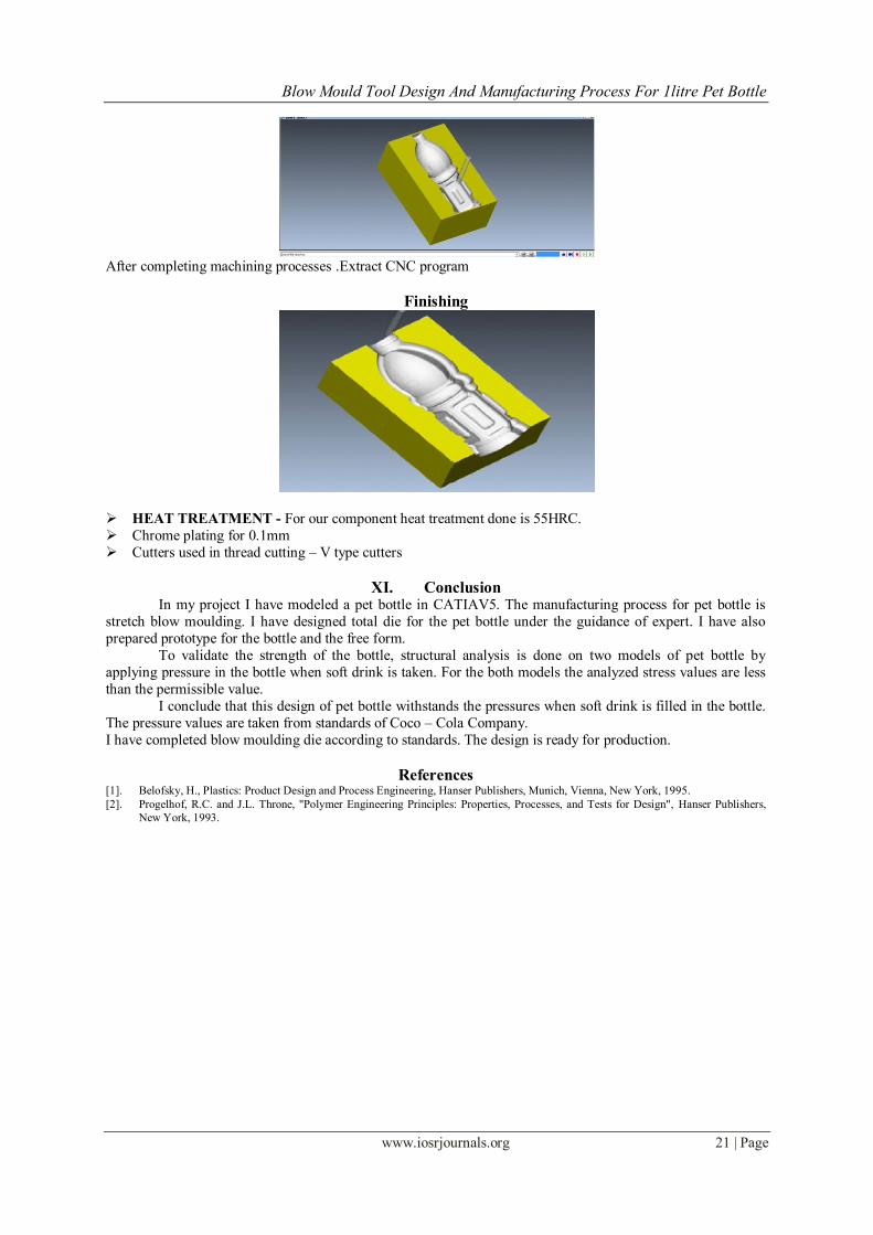
After completing machining processes .Extract CNC program
Finishing
HEAT TREATMENT - For our component heat treatment done is 55HRC.
Chrome plating for 0.1mm
Cutters used in thread cutting – V type cutters
XI. Conclusion In my project I have modeled a pet bottle in CATIAV5. The manufacturing process for pet bottle is
stretch blow moulding. I have designed total die for the pet bottle under the guidance of expert. I have also
prepared prototype for the bottle and the free form.
To validate the strength of the bottle, structural analysis is done on two models of pet bottle by
applying pressure in the bottle when soft drink is taken. For the both models the analyzed stress values are less
than the permissible value.
I conclude that this design of pet bottle withstands the pressures when soft drink is filled in the bottle.
The pressure values are taken from standards of Coco – Cola Company.
I have completed blow moulding die according to standards. The design is ready for production.
References [1]. Belofsky, H., Plastics: Product Design and Process Engineering, Hanser Publishers, Munich, Vienna, New York, 1995.
[2]. Progelhof, R.C. and J.L. Throne, "Polymer Engineering Principles: Properties, Processes, and Tests for Design", Hanser Publishers,
New York, 1993.


![Parameterized Modeling of Blow-Moulds for Designer …file.seekpart.com/keywordpdf/2011/1/13/2011113174443939.pdf · ing of a bottle blow-mould [2] focused on the plastic forming](https://img.pdfslide.us/doc/110x75/5b5e71d07f8b9a553d8c8f6b/parameterized-modeling-of-blow-moulds-for-designer-file-ing-of-a-bottle-blow-mould.jpg)