Embed Size (px)
Citation preview

INSTRUCTION MANUAL V58043
REVISION H
Blow-down valve

Index
PageOperational Limits . . . . . . . . . . . . . . . . . . . . . . . . . . . . . . . . . . . . . . . . . . . . . . . . . . . . . . . . . . . . . . . 4
General Information . . . . . . . . . . . . . . . . . . . . . . . . . . . . . . . . . . . . . . . . . . . . . . . . . . . . . . . . . . . . . 4For Installing Sweat Connections . . . . . . . . . . . . . . . . . . . . . . . . . . . . . . . . . . . . . . . . . . . . . . . . . . 4For Installing NPT Connections . . . . . . . . . . . . . . . . . . . . . . . . . . . . . . . . . . . . . . . . . . . . . . . . . . . . 4
Valve Accessories . . . . . . . . . . . . . . . . . . . . . . . . . . . . . . . . . . . . . . . . . . . . . . . . . . . . . . . . . . . . . . . . 4Drain Caps and Cartridge Caps . . . . . . . . . . . . . . . . . . . . . . . . . . . . . . . . . . . . . . . . . . . . . . . . . . . . 5How To Use Pressure Taps To Measure System Operating Conditions . . . . . . . . . . . . . . . . . 6Pipe Hanging Installations . . . . . . . . . . . . . . . . . . . . . . . . . . . . . . . . . . . . . . . . . . . . . . . . . . . . . . . . . 6
MC Circuit Setter Valves . . . . . . . . . . . . . . . . . . . . . . . . . . . . . . . . . . . . . . . . . . . . . . . . . . . . . . . . . 6Description . . . . . . . . . . . . . . . . . . . . . . . . . . . . . . . . . . . . . . . . . . . . . . . . . . . . . . . . . . . . . . . . . . . . . . 6Installation Instructions . . . . . . . . .. . . . . . . . . . . . . . . . . . . . . . . . . . . . . . . . . . . . . . . . . . . . . . . . . . . 6How To Use B&G Circuit Setter Balance Valves for Pre-Set Flow Balancing . . . . . . . . . . . . 6How To Use B&G Circuit Setters to Proportionally Balance a System . . . . . . . . . . . . . . . . . . 7How To Use B&G Cicuit Setter Balance Valves as Flow Meters . . . . . . . . . . . . . . . . . . . . . . . 7How To Use B&G Circuit Setter Balance Valves as an Isolation Valve . . . . . . . . . . . . . . . . . . 7How To Use the Memory Stop Feature . . . . . . . . . . . . . . . . . . . . . . . . . . . . . . . . . . . . . . . . . . . . . 7Service Instructions . . . . . . . . . . . . . . . . . . . . . . . . . . . . . . . . . . . . . . . . . . . . . . . . . . . . . . . . . . . . . . . 7Insulation . . . . . . . . . . . . . . . . . . . . . . . . . . . . . . . . . . . . . . . . . . . . . . . . . . . . . . . . . . . . . . . . . . . . . . . . 7
AC Circuit Sentry Automatic Flow Limiting Valves . . . . . . . . . . . . . . . . . . . . . . . . . . . . . . . . 8Description . . . . . . . . . . . . . . . . . . . . . . . . . . . . . . . . . . . . . . . . . . . . . . . . . . . . . . . . . . . . . . . . . . . . . . 8Installation Instructions . . . . . . . . . . . . . . . . . . . . . . . . . . . . . . . . . . . . . . . . . . . . . . . . . . . . . . . . . . . 8Operating Instructions . . . . . . .. . . . . . . . . . . . . . . . . . . . . . . . . . . . . . . . . . . . . . . . . . . . . . . . . . . . . 8How To Use B&G Circuit Sentry Flow Limiting Valve Pressure Taps to DetermineProper Functioning of Valve . . . . . . . . . . . . . . . . . . . . . . . . . . . . . . . . . . . . . . . . . . . . . . . . . . . . . . . 8Service Instructions . . . . . . . . . . . . . . . . . . . . . . . . . . . . . . . . . . . . . . . . . . . . . . . . . . . . . . . . . . . . . . . 8Insulation .. . . . . . . . . . . . . . . . . . . . . . . . . . . . . . . . . . . . . . . . . . . . . . . . . . . . . . . . . . . . . . . . . . . . . . . . 8
ACL Low Flow Circuit Sentry Valve . . . . . . . . . . . . . . . . . . . . . . . . . . . . . . . . . . . . . . . . . . . . . . . 9Description . . . . . . . . . . . . . . . . . . . . . . . . . . . . . . . . . . . . . . . . . . . . . . . . . . . . . . . . . . . . . . . . . . . . . . . 9Installation Instructions . . . . .. . . . . . . . . . . . . . . . . . . . . . . . . . . . . . . . . . . . . . . . . . . . . . . . . . . . . . . 9Low Flow Circuit Sentry Model ACL Valves with Sweat Connections . . . . . . . . . . . . . . . . . . . 9Low Flow Circuit Sentry Model ACL Valves with NPT Connections . . . . . . . . . . . . . . . . . . . . 9Low Flow Circuit Sentry Model ACL Valves Flow Limiting Cartridge Installation . . . . . . . . 9How To Use B&G Low Flow Circuit Sentry Model ACL Flow Limiting Valves forPre-set Flow Balancing . . . . . . . . . . . . . . . . . . . . . . . . . . . . . . . . . . . . . . . . . . . . . . . . . . . . . . . . . . . . 10How To Use Pressure Taps (P/T Ports) to Measure System Operating Conditions . . . . . . . 10Service Instructions .. . . . . . . . . . . . . . . . . . . . . . . . . . . . . . . . . . . . . . . . . . . . . . . . . . . . . . . . . . . . . . . 10Insulation . . . . . . . . . . . . . . . . . . . . . . . . . . . . . . . . . . . . . . . . . . . . . . . . . . . . . . . . . . . . . . . . . . . . . . . . . 10
AM Circuit Sentry Flo-Setter Balance & Commissioning Valves . . . . . . . . . . . . . . . . . . . . 10Description . . . . . . . . . . . . . . . . . . . . . . . . . . . . . . . . . . . . . . . . . . . . . . . . . . . . . . . . . . . . . . . . . . . . . . 10Installation Instructions . . . . . . . . . . . . . . . . . . . . . . . . . . . . . . . . . . . . . . . . . . . . . . . . . . . . . . . . . . . . 10Circuit Sentry Flo-Setter Balance Valves with NPT Connections . . . .. . . . . . . . . . . . . . . . . . . . . . . . . . . . . . 11How To Use B&G Circuit Sentry Flo-Setter Balancing & Commissioning Valves forPre-Set Flow Balancing . . . . . . . . .. . . . . . . . . . . . . . . . . . . . . . . . . . . . . . . . . . . . . . . . . . . . . . . . . . . . 11How To Use B&G Circuit Sentry Flo-Setter to Proportional Balance a System . . . . . . . . . . . 11Service Instructions . . . . . . . . . . . . . . . . . . . . . . . . . . . . . . . . . . . . . . . . . . . . . . . . . . . . . . . . . . . . . . . . 11Insulation . . . . . . . . . . . . . . . . . . . . . . . . . . . . . . . . . . . . . . . . . . . . . . . . . . . . . . . . . . . . . . . . . . . . . . . . . 11
2

Index (continued)
PageAA Ultra Setter Pressure Independent Control Valves . . . . . . . . . . . . . . . . . . . . . . . . . . . . . . . 11Description . . . . . . . . . . . . . . . . . . . . . . . . . . . . . . . . . . . . . . . . . . . . . . . . . . . . . . . . . . . . . . . . . . . . . . . . . 11Installation Instructions . . . . . . . . . . . . . . . . . . . . . . . . . . . . . . . . . . . . . . . . . . . . . . . . . . . . . . . . . . . . . . 12Ultra Setter Pressure Independent Control Valves with NPT Connections . . . . . . . . . . . . . . . 12Ultra Setter Pressure Independent Control Valves with 0-10 VDC Analog Actuator . . . . . . . 12Ultra Setter Pressure Independent Control Valves with 24 VAC 3-Position Actuator . . . . . . 13How To Use B&G Ultra Setter Pressure Independent Control Valves forPre-Set Flow Balancing . . . . . . . . . . . . . . . . . . . . . . . . . . . . . . . . . . . . . . . . . . . . . . . . . . . . . . . . . . . . . 14How To Use B&G Ultra Setter to Commission a System . . . . . . . . . . . . . . . . . . . . . . . . . . . . . . . 14Service Instructions . . . . . . . . . . . . . . . . . . . . . . . . . . . . . . . . . . . . . . . . . . . . . . . . . . . . . . . . . . . . . . . . . . 14Insulation . . . . . . . . . . . . . . . . . . . . . . . . . . . . . . . . . . . . . . . . . . . . . . . . . . . . . . . . . . . . . . . . . . . . . . . . . . 14
MV Venturi/Ball Valve Combination . . . . . . . . . . . . . . . . . . . . . . . . . . . . . . . . . . . . . . . . . . . . . . . . 15Description . . . . . . . . . . . . . . . . . . . . . . . . . . . . . . . . . . . . . . . . . . . . . . . . . . . . . . . . . . . . . . . . . . . . . . . . . 15Installation Instructions . . . . . . . . . . . . . . . . . . . . . . . . . . . . . . . . . . . . . . . . . . . . . . . . . . . . . . . . . . . . . . . 15Operating Instructions . . . . . . . . . . . . . . . . . . . . . . . . . . . . . . . . . . . . . . . . . . . . . . . . . . . . . . . . . . . . . . 15How To Use B&G MV Venturi/Ball Valves as an Isolation Valve . . . . . . . . . . . . . . . . . . . . . . . . . . 15How To Use the Memory Stop Feature . . . . . . . . . . . . . . . . . . . . . . . . . . . . . . . . . . . . . . . . . . . . . . . 15Service Instructions . . . . . . . . . . . . . . . . . . . . . . . . . . . . . . . . . . . . . . . . . . . . . . . . . . . . . . . . . . . . . . . . . . 15Insulation . . . . . . . . . . . .. . . . . . . . . . . . . . . . . . . . . . . . . . . . . . . . . . . . . . . . . . . . . . . . . . . . . . . . . . . . . . . 15
UBY Y-Strainer Combination Ball Valve . . . . . . . . . . . . . . . . . . . . . . . . . . . . . . . . . . . . . . . . . . . . . 16Description . . . . . . . . . . . . . . . . . . . . . . . . . . . . . . . . . . . . . . . . . . . . . . . . . . . . . . . . . . . . . . . . . . . . . . . . . 16Installation Instructions . . . . . . . . . . . . . . . . . . . . . . . . . . . . . . . . . . . . . . . . . . . . . . . . . . . . . . . . . . . . . . 16Operating Instructions . . . . . . . . . . . . . . . . . . . . . . . . . . . . . . . . . . . . . . . . . . . . . . . . . . . . . . . . . . . . . . 16Service Instructions . . . . . . . . . . . . . . . . . . . . . . . . . . . . . . . . . . . . . . . . . . . . . . . . . . . . . . . . . . . . . . . . . 16Insulation . . . . . . . . . . . . . . . . . . . . . . . . . . . . . . . . . . . . . . . . . . . . . . . . . . . . . . . . . . . . . . . . . . . . . . . . . . 16
UBYL Low Y-Strainer Combination Ball Valve . . . . . . . . . . . . . . . . . . . . . . . . . . . . . . . . . . . . . . . 16Description . . . . . . . . . . . . . . . . . . . . . . . . . . . . . . . . . . . . . . . . . . . . . . . . . . . . . . . . . . . . . . . . . . . . . . . . 16Installation Instructions . . . . . . . . . . . . . . . . . . . . . . . . . . . . . . . . . . . . . . . . . . . . . . . . . . . . . . . . . . . . . . 17Low Flow Model UBYL Y-Strainer Valves with Sweat Connections . . . . . . . . . . . . . . . . . . . . . . . 17Low Flow Model UBYL Y-Strainer Valves with NPT Connections . . . . . . . . . . . . . . . . . . . . . . . . 17How To Use B&G Low Flow Model UBYL Y-Strainer Valves . . . . . . . . . . . . . . . . . . . . . . . . . . . . . . 17How To Use Pressure Taps (P/T Ports) to Measure System Operating Conditions . . . . . . . . . 17Service Instructions . . . . . . . . . . . . . . . . . . . . . . . . . . . . . . . . . . . . . . . . . . . . . . . . . . . . . . . . . . . . . . . . . . 17Insulation . . . . . . . . . . . . . . . . . . . . . . . . . . . . . . . . . . . . . . . . . . . . . . . . . . . . . . . . . . . . . . . . . . . . . . . . . . 18
UBV Union-Ended Ball Valve . . . . . . . . . . . . . . . . . . . . . . . . . . . . . . . . . . . . . . . . . . . . . . . . . . . . . . . 18Description . . . . . . . . . . . . . . . . . . . . . . . . . . . . . . . . . . . . . . . . . . . . . . . . . . . . . . . . . . . . . . . . . . . . . . . . . 18Installation Instructions . . . . . . . . . . . . . . . . . . . . . . . . . . . . . . . . . . . . . . . . . . . . . . . . . . . . . . . . . . . . . . 18Operating Instructions . . . . . . . . . . . . . . . . . . . . . . . . . . . . . . . . . . . . . . . . . . . . . . . . . . . . . . . . . . . . . . . 18Service Instructions . . . . . . . . . . . . . . . . . . . . . . . . . . . . . . . . . . . . . . . . . . . . . . . . . . . . . . . . . . . . . . . . . . 18
UA Union Accessory . . . . . . . . . . . . . . . . . . . . . . . . . . . . . . . . . . . . . . . . . . . . . . . . . . . . . . . . . . . . . . . . 19Description . . . . . . . . . . . .. . . . . . . . . . . . . . . . . . . . . . . . . . . . . . . . . . . . . . . . . . . . . . . . . . . . . . . . . . . . . . 19Installation Instructions . . . . . . . . . . . . . . . . . . . . . . . . . . . . . . . . . . . . . . . . . . . . . . . . . . . . . . . . . . . . . . 19Operating Instructions . . . . . . . . . . . . . . . . . . . . . . . . . . . . . . . . . . . . . . . . . . . . . . . . . . . . . . . . . . . . . . 19Service Instructions . . . . . . . . . . . . . . . . . . . . . . . . . . . . . . . . . . . . . . . . . . . . . . . . . . . . . . . . . . . . . . . . . . 19
SH Hose . . . . . . . . . . . . . . . . . . . . . . . . . . . . . . . . . . . . . . . . . . . . . . . . . . . . . . . . . . . . . . . . . . . . . . . . . . . . 19Description . . . . . . . . . . . . . . . . . . . . . . . . . . . . . . . . . . . . . . . . . . . . . . . . . . . . . . . . . . . . . . . . . . . . . . . . . 19Installation Instructions . . . . . . . . . . . . . . . . . . . . . . . . . . . . . . . . . . . . . . . . . . . . . . . . . . . . . . . . . . . . . . 19Service Instructions . . . . . . . . . . . . . . . . . . . . . . . . . . . . . . . . . . . . . . . . . . . . . . . . . . . . . . 20
3


HOW TO USE BELL & GOSSETT CIRCUIT SETTERSTO PROPORTIONALLY BALANCE A SYSTEM
1. Open fully all Circuit Setters on a single pump system.
2. If more than one branch circuit is used, start the balance pro-cedure by reading all of the flows to the units in a branch.Each unit (coil) should have its own Circuit Setter for flowbalancing. Using Bell & Gossett RP-250B readout probes,sequentially attach a Bell & Gossett differential pressurereadout kit to the readout valves (P/T ports) on each CircuitSetter balance valve.
3. Using Side #2 of the Bell & Gossett Circuit Setter BalanceValve Calculator (V91483), with the top hairline set on zerofor the size Circuit Setter being read, read the flow corre-sponding to the pressure drop read with the readout kit.
4. Calculate the ratio of the actual flow to the design flow foreach unit in the branch. This is the proportional flow rate.(Actual flow divided by design flow).
5. Select the Circuit Setter with the lowest proportional flowrater. This Circuit Setter is left in the full open position. Everyother Circuit Setter in the branch is then reset to the sameproportional flow rate.
6. If there are additional branches, repeat the Steps #3, #4, and#5 above for each branch.
7. After all branches have been proportionally balanced, meas-ure the full open flows on the Circuit Setters installed on therisers. Calculate the proportional ratio of each riser CircuitSetter and select the one with the lowest proportional ratio.This Circuit Setter is left fully open and the other riser CircuitSetters are adjusted to this same ratio as described in Step#5 above.
8. Adjust pump flow so that circuits are receiving their designflow. This can be accomplished by adjusting a Circuit Setterbalance valve installed on the pump discharge or by chang-ing the pump impeller size.
HOW TO USE BELL & GOSSETT CIRCUIT SETTERBALANCE VALVES AS FLOW METERS
1. Energize the zone, circuit, and/or system pump(s) as applicable.
2. Using Bell & Gossett Model RP-250B Readout Probes, sequentially attach a Bell & Gossett differential pressurereadout kit to the readout valves on each Circuit Setter Balance Valve.
3. Read the differential pressure across the orifice of the CircuitSetter balance valve.
4. Using Side #2 of the Circuit Setter Balance Valve Calculator(V91483), set the hairline over the degree of closure as indi-cated by the part of the red plastic knob or indicator plateparallel to the degree of closure noted on the calibrationplate, and read actual GPM flowing through the Circuit Setteropposite the gauge reading head loss noted in the white sec-tion of Side #2.
NOTE:
• If the system contains a liquid with a specific gravity and/orviscosity higher or lower than that of water, apply the appro-priate correction factor noted in these instructions to obtainthe actual GPM for the system liquid.
HOW TO USE BELL & GOSSETT CIRCUIT SETTERBALANCE VALVES AS AN ISOLATION VALVE
1. Move the adjustment knob or stem until the position indica-tor aligns with the closed position on the calibration plate.
2. Close the isolation valve on the other side of the equipmentto be serviced.
3. Open the drain valve to drain the system between the CircuitSetter and the second isolation valve.
HOW TO USE THE MEMORY STOP FEATURE
1. Make the final degree of closure setting.
2. Loosen the memory stop locking screw in the slot on the topof red knob.
3. Slide the memory stop screw in the slot (counter-clockwisefor ½” thru 1” sizes and clockwise for 1-1/4” thru 3” sizes)until screw stops.
4. Tighten the memory stop screw.
SERVICE INSTRUCTIONSPeriodically inspect the Circuit Setter for signs of leakage orcorrosion.
INSULATION
Bell & Gossett recommends that insulation be attached to theCircuit Setter after the system has been balanced.
NOTE:
Tape or other acceptable means should be used to secure theinsulation to the Circuit Setter balance valve.
7
WARNING: Hot water leakage can occur from readout valves (P/T ports) during probe insertion and duringhookup of readout kit. Follow the instruction manuals sup-plied with readout probes and readout kits for safe use. Failure to follow these instructions could result in serious per-sonal injury or death and property damage.
WARNING: Hot water leakage can occur from readout valves (P/T ports) during probe insertion and duringhookup of readout kit. Follow the instruction manuals sup-plied with readout probes and readout kits for safe use. Failure to follow these instructions could result in serious per-sonal injury or death and property damage.
WARNING: Check for proper sealing when using as an isolation valve. If the seat is not sealing properly, liquidwill continue to flow from the drain valves. In this case, theCircuit Setter must be isolated from the system and replaced.Failure to follow these instructions could result in serious per-sonal injury or death and property damage.
WARNING: Corrosion or leakage are indications that the Circuit Setter must be replaced. Failure to followthese instructions could result in serious personal injury ordeath and property damage.
NOTICE: If a high degree of throttling of flow at pump discharge is required, Bell & Gossett recommends thatthe pump impeller be sized to produce design flow. This willreduce electrical energy consumption


MV VENTURI/BALL VALVE COMBINATION
DESCRIPTION
The Bell & Gossett Model MV is a combination calibrated bal-ance, commissioning and positive shutoff valve for use in HVACsystems. An efficient brass venturi design provides accurateflow balancing with minimal system pressure loss. Valves arefurnished with two readout valves (pressure and temperatureports), standard port ball valve with memory stop, and a hang-ing ID tag for commissioning. A variety of end connections areavailable on both the fixed and union ends. Venturi/Ball valveprovides highly accurate flow measurement capabilities.
INSTALLATION INSTRUCTIONS
The valve should be installed on the return side of the coil withunion end on the upstream side and other end on the down-stream side, except when used on the bypass line. Install theunit so that the flow arrow on the body housing points in thedirection of flow.
OPERATING INSTRUCTIONS
1. Energize the zone, circuit and/or system pump(s) as appli-cable.
2. Using Bell & Gossett Model RP-250B Readout Probes, sequentially attach a Bell & Gossett differential pressurereadout kit to the readout valves (P/T ports) on each Venturi/Ball valve.
3. Read the differential pressure across the orifice of the Venturi/Ball valve.
4. Use the differential pressure data sheet #EP-600 of the Venturi/Ball valve to read actual GPM.
HOW TO USE BELL & GOSSETT MVVENTURI/BALL VALVES AS AN ISOLATION VALVE
1. Move the handle until the position indicator aligns with theclosed position on the valve.
2. Close the isolation valve on the other side of the equipmentto be serviced.
3. Open the drain valve to drain the system between the Ven-turi/Ball valve and the second isolation valve.
HOW TO USE THE MEMORY STOP FEATURE
1. Make the final degree of closure setting.
2. Loosen the handle nut and rotate memory stop until againstthe body locking.
3. Tighten the handle nut.
SERVICE INSTRUCTIONS
Periodically inspect the MV Venturi/Ball valve for signs of leak-age or corrosion.
INSULATION
Bell & Gossett recommends that insulation be attached to theVenturi/Ball valve after the system has been balanced.
NOTE:
Tape or other acceptable means should be used to secure theinsulation to the Venturi/Ball valve.
15
CAUTION: Hot un-insulated surfaces can cause burns to the skin. Do not touch hot surfaces. Failure to followthese instructions could result in personal injury.
WARNING: Corrosion or leakage are indications that the MV Venturi/Ball valve must be replaced. Failure to follow these instructions could result in serious personalinjury or death and property damage.
WARNING: Hot water leakage can occur from readout valves (P/T ports) during probe insertion and duringhookup of readout kit. Follow the instruction manuals sup-plied with readout probes and readout kits for safe use. Fail-ure to follow these instructions could result in seriouspersonal injury or death and property damage.
WARNING: Check for proper sealing when using as an isolation valve. If the seat is not sealed properly, liquidwill continue to flow from the drain valves. In this case, theMV Venturi/Ball valve must be isolated from the system andreplaced. Failure to follow these instructions could result inserious personal injury or death and property damage.

UBY Y-STRAINER COMBINATIONBALL VALVE
DESCRIPTION
Y-strainer valves are of brass construction with an integratedball valve, strainer, blow-down drain valve, and union with tail-piece.
INSTALLATION INSTRUCTIONS
1. The valves must be installed on the supply side of the coilwith fixed end on the upstream side and other end on thedownstream side.
2. When installing the Y-strainer valves, space around the unitsmust be provided to move the valve handle to the shutoffposition and to remove the strainer from the strainer bodyfor cleaning.
3. The Y-strainer must be installed with the strainer chamberdown to prevent air binding and also to allow accumulateddirt to be blown down from the strainer.
OPERATING INSTRUCTIONS
The Y-strainer can be used to isolate Hydronic equipment forrepairs and/or to drain the system. To close the Y-strainer ballvalve, move the handle a quarter of a turn until the handle isperpendicular to the valve and piping.
If the Y-strainer pressure drop becomes excessive, accumu-lated dirt and debris should be blown down through the blow-down line (if installed) to a train. If a blow-down line is notinstalled, see the service instructions for removing and cleaningthe strainer. The Y-strainers have construction with an inte-grated ball valve which will function as a service valve.
SERVICE INSTRUCTIONS
If excessive pressure drop is measured across the Y-strainer,the internal strainer has collected dirt and debris and needs tobe cleaned. Install a blow-down line (hose), then open blow-down drain valve. If blowing down the strainer has not solvedthe pressure drop problem, the Y-strainer must be disassem-bled and the strainer cleaned.
To clean the strainer, isolate the Y-strainer by shutting off theball valves on the upstream and downstream of the Y-strainer.Allow the system to cool down to 100° F (38° C) or less.
Using the appropriate sized wrench, remove the blow-downdrain valve from the brass strainer cap on the bottom of thevalve body. Completely remove the strainer cap from the valvebody. Carefully remove the strainer. Clean the strainer in waterto remove collected debris. Reinstall the strainer and thestrainer cap. Tighten to the appropriate torque level as listedabove. Reinstall the blow-down drain valve per instructionsabove. Pressurize the system and check for leaks.
Periodically inspect the Y-strainer for signs of corrosion or leakage. If corrosion or leakage is noted, the Y-strainer mustbe replaced.
INSULATION
Bell & Gossett recommends that insulation be attached to theY-strainer valve after the system has been balanced.
NOTE:
Tape or other acceptable means should be used to secure theinsulation to the Y-Strainer Valve.
UBYL LOW Y-STRAINERCOMBINATION BALL VALVE
DESCRIPTION
Low Flow Y-strainer Valves are made of brass construction withan integrated ball valve and strainer.
16
CAUTION: Failure to use proper hose connection to the blow-down drain valve may result in serious per-sonal injury and property damage.
CAUTION: Installation and maintenance must be per- formed by a qualified professional. Service should notbe performed on any valve in an active Hydronic loop. Beforeattempting to make any required adjustments, properly iso-late and drain the branch loops that require service and allowthe valves to reach a safe handling temperature (below 100°F [38° C]) and zero pressure condition. Use proper safetyequipment including gloves, goggles, or similar tools to avoidcontact with system fluids and common hazards. Failure tofollow these instructions could result in personal injury andproperty damage.
WARNING: Corrosion or leakage are indications that the Y-strainer valve must be replaced. Failure to followthese instructions could result in serious personal injury ordeath and property damage.

INSTALLATION INSTRUCTIONS
Model UBYL Low Flow Y-strainer Valves are uni-directionalvalves and should be mounted in the supply pipe. Be sure toinstall the Model UBYL Low Flow Y-strainer valve with the arrowpointing in the direction of flow and the strainer chamber downto prevent air binding and to allow materials to collect in thestrainer. Be sure to provide enough space around the valve toremove the strainer from the valve body for cleaning.
LOW FLOW MODEL UBYL Y-STRAINER VALVESWITH SWEAT CONNECTIONS
For installing sweat connections, make sure that the flow limit-ing cartridge has not yet been installed in the valve. When con-firmed, proceed as follows:
a) Clean tube ends and valve connections thoroughly per goodpiping practices with a fine grade emery cloth or fine gritsandpaper.
b) For soldering, use 95-5 (Tin-Antimony) solder and a goodgrade of flux.
c) Use a torch with a sharp pointed flame.
d) When sweating the joints, adjust the valve to the full openposition, then wrap the valve with a cool wet rag and thendirect the flame with care to avoid subjecting the valve toexcessive heat. Allow the valve to cool before touching oroperating.
e) Check the soldered connection for leaks.
LOW FLOW MODEL UBYL Y-STRAINER VALVESWITH NPT CONNECTIONS
Apply pipe compound conservatively to male connecting fittings only. After installation, check all joints for leakage andre-tighten if necessary.
OPERATION INSTRUCTIONS
HOW TO USE BELL & GOSSETT LOW FLOWMODEL UBYL Y-STRAINER VALVES
Y-strainer can be used to isolate hydronic equipment for repairsand/or to drain the system. To close the Y-strainer ball valve,move the handle a quarter of a turn until the handle is perpen-dicular to the valve and piping.
Before system start up, flush the hydronic system as part ofcommissioning. Make sure the drain valve cap is tightenedproperly. Start the system and inspect the Low Flow ModelUBYL Y-strainer valve for leakage.
HOW TO USE PRESSURE TAPS (P/T PORTS) TOMEASURE SYSTEM OPERATING CONDITIONS
Using Bell & Gossett Model RP-250B, readout probes, attachBell & Gossett differential pressure readout kit to the readoutvalves (P/T ports) on the Low Flow Model UBYL Y-StrainerValves.
Read the differential pressure from the coil inlet isolation valve(typically strainer) to coil outlet isolation valve (typically flow limiting balancing valve). Differential value should be betweenthe sum of the coil and control valve pressure drop and 60 psi,depending upon the amount of control being exercised by theflow limiting valve function for balance. Valves should be installed with coil and barrels isolated and drained.
If Y-strainer pressure drop becomes excessive, accumulateddirt and contaminants should be blown through the blow-downline (if installed) to a drain. If a blow-down line is not installed,see the service instructions for removing and cleaning thestrainer. The Y-strainers have construction with an integratedball valve and will function as a service valve.
SERVICE INSTRUCTIONS
If excessive pressure drop is noted across the Y-Strainer, theinternal strainer has most likely collected a lot of dirt or debrisand needs to be cleaned. Install blow-down line (hose) to thedrain valve on the strainer chamber then open the drain valve.If flushing the strainer at this point has not solved the pressuredrop problem, the Y-strainer must be disassembled and strainerto be cleaned.
17
CAUTION: Use of improper procedures to sweat valve model with union connection into system can damagevalve. Before installing sweat union connection to valve, re-move the union nut and O-ring from the valve body, thenunion tailpiece with union nut must be sweated (soldered) intoplace. Failure to follow this instruction could result in propertydamage and/or moderate personal injury.
CAUTION: Heat associated with the use of silver solder may damage valve components and void theproduct warranty. Do not use silver solder. Failure to followthese instructions could result in property damage and/ormoderate personal injury.
CAUTION: Excessive use of solder or flux may result in damage to the shutoff valve seat and ball. Do notuse excessive solder or flux. Failure to follow these instruc-tions can result in moderate personal injury and/or propertydamage.
CAUTION: The use of PTFE impregnated pipe compound and PTFE tape on pipe threads provideslubricity. Care should be taken to prevent over tighteningwhich may damage the valve body. Failure to follow these in-structions can result in personal injury and/or property damage.
CAUTION: Hot un-insulated surfaces can cause burns to the skin. Do not touch hot surfaces. Failure to followthese instructions could result in personal injury.
WARNING: Hot water leakage can occur from readout valves (P/T ports) during probe insertion and duringhookup of readout kit. Follow the instruction manuals supplied with readout probes and readout kits for safe use.Failure to follow these instructions could result in serious personal injury or death and property damage.

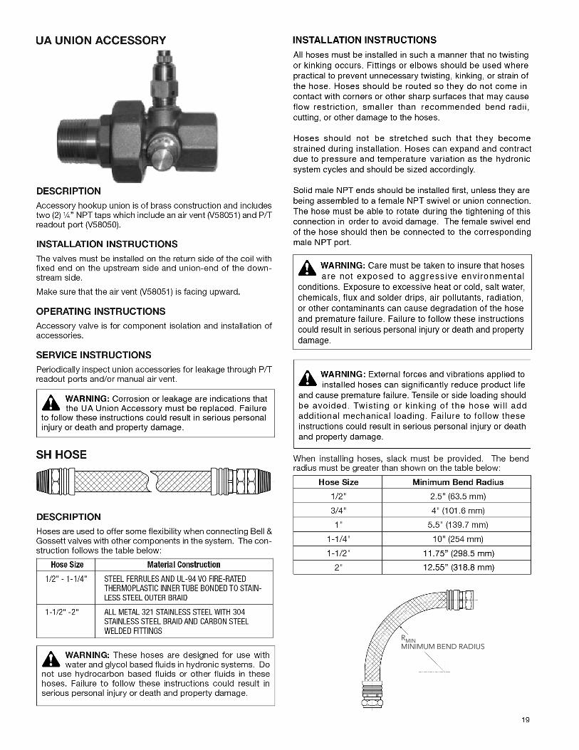
RMINMINIMUM BEND RADIUS

Xylem Inc. 8200 N. Austin Avenue Morton Grove, Illinois 60053 Phone: (847) 966-3700 Fax: (847) 965-8379www.bellgossett.com
Bell & Gossett is a trademark of Xylem Inc. or one of its subsidiaries. © 2017 Xylem Inc. V58043H March 2017 20
Hose too short
Strained
* Loctite and Loctite 567 are registered trademarks of Henkel AG & Co.**RectorSeal No. 5 is a registered trademark of RectorSeal Corporation.


![MARWARI COLLEGE, RANCHI Syllabus/Botany... · Paper -1, Diversity, Classification of Plant Kingdom & Thallophyta [40 Lectures] Instructions to Paper Setters Full Marks: 50 Paper setters](https://img.pdfslide.us/doc/110x75/605e70cb942fc42e6754cf5b/marwari-college-syllabusbotany-paper-1-diversity-classification-of-plant.jpg)