Embed Size (px)
Citation preview

fw
BLOCK II SOLID ROCKET MOTOR (SRM)CONCEPTUAL DESIGN STUDY
CONTRACT NAS 8-37295
FINAL REPORT - VOLUME I
APPENDICES
Prepared for:
GEORGE C. MARSHALL SPACE FLIGHT CENTER
NATIONAL AERONAUTICS AND SPACE ADMINISTRATION
Marshall Space Flight Center, Alabama 35812
(JAS&-.CB-179051) BLOCK 2 SCLID EOCLET BO_OB(SRE) CCICBPTO&L CBSIGJ $$UDI. ¥CLUBB 1:
&_PZmDZCB5 Einal Eeport (atlantic Eesearch
coEp.) 268 p Avail: _215 BE: 112/!!F t01CSCL 211t G3/20
B87-22000 /0zlclas0071137 :
Submitted by:
ATLANTIC RESEARCH CORPORATION
7511 WELLINGTON ROAD
GAINESVILLE, VIRGINIA - 22065-1699
TR-PL-12126' I=,RQI:SULSIQN EPlVISION:
31 December 1986
J
https://ntrs.nasa.gov/search.jsp?R=19870012567 2020-04-19T18:19:19+00:00Z
BLOCK II SOLID ROCKET MOTOR (SRM)CONCEPTUAL DESIGN STUDY
CONTRACT NAS 8-3729_
FINAL REPORT - VOLUME IAPPENDICES
Prepared for:
George C. Marshall Space Flight CenterNational Aeronautics and Space AdministrationMarshall Space Flight Center, Alabama 35812
Submitted by:
Atlantic Research CorporationPropulsion Division
7_11 Wellington RoadGainesville_ Virginia 22065-1699
TR-PL-12126 31 December 1986
TABLE OF CONTENTS
VOLUME I - FINAL REPORT
TITLE PAGE
APPENDIX A MID-TERM REPORT A-I
APPENDIX B SEAL DESIGN/PERFORMANCE INFORMATION B-I
APPENDIX A
MID-TERM REPORT
(SUPERSEDED AND REVISED)
.,.OCKo..so..o.OCKE MO O.(S.M)NCEPTUAL DESIGN STUDCONTRACT NAS 8 - 37295
MID-TERM REPORT
SUBMITTED TO:
NATIONAL AERONAUTICS AND SPACE ADMINISTRATIONMARSHALL SPACE FLIGHT CENTER, ALABAMA 35812
SUBMITTED BY:
ATLANTIC RESEARCH CORPORATIONPROPULSION DIVISION
GAINESVILLE, VIRGINIA 22065
TR-PL 12127 |
REV. A
FOREWORD
This document is submitted as a Midterm Report satisfying the following
requirements of Contract NAS8-37295, Conceptual Design Studies of a Block II Space
Shuttle Solid Rocket Motor (SRM)=
1) Conceptual Design Package (Preliminary),
2) Preliminary Development and Validation Plan (Preliminary).
TABLE OF CONTENTS
SECTION PAGE
FOREWORD ii
1.0 INTRODUCTION
I. 1 ORGANIZATION
1.2 APPROACH
1.3 PRELIMINARY DESIGN CONCEPT
I-I
I-I
I=I
I=#
2.0 TRADE
2.1
2.2
2.3
2.4
2.5
2.6
2,7
STUDIES
DESIGN APPROACH TRADE STUDY (UPDATED 12/19/86)
2.1.1 CANDIDATE DESIGN APPROACHES
2.1.2 DISCUSSION OF MONOLITHIC SRM DESIGN ISSUES
2.1.3 RELIABILITY ASSESSMENT
2.1.# PAYLOAD CAPABILITY ASSESSMENT
2.1.5 COST ASSESSMENT
2.1.6 RANKING AND SELECTION OF PREFERREDDESIGN APPROACH
SRM MOTOR CASE TRADE STUDY
JOINTS AND SEALS TRADE STUDIES
INSULATION TRADE STUDIES
2.4.1 FABRICATION PROCESS TRADE STUDY
2.4.2 CASE INSULATION TRADE STUDY
PROPELLANT TRADE STUDIES
NOZZLE TRADE STUDIES
2.6.1 INTRODUCTION
2.6.2 NOZZLE-TO-CASE JOINT HARDWARE
2.6.3 NOZZLE THROAT LINER MATERIALS
TRANSPORTATION, HANDLING AND ASSEMBLY
2.7.1
2.7.2
2.7.3
2.7.#
2.7.5
TRANSPORTATION
HANDLING
ASSEMBLY
ENVIRONMENTAL REGULATIONS IMPACT
CONCLUSIONS
2-1
2-2
2-2
2-7
2-11
2-13
2-15
2=18
2-18
2=#2
2-66
2-70
2-7#
2-79
2-90
2-90
2-91
2-97
2-10#
2-10#
2-107
2-108
2-108
2=109
°.,
III
REV. A
TABLE OF CONTENTS (CONTINUED)
SECTION PAGE
3.0 DESIGN STUDIES
3.1 JOINT DESIGN STUDIES - STRUCTURAL ANALYSIS
3.2 NOZZLE DESIGN STUDIES AND ANALYSES
3,2,1 ASSESSMENT OF CURRENT DESIGN
3.2.2 NOZZLE SUBASSEMBLY _OINT SEALS
3.3
3,#
3.5
3.2.3 NEW DESIGN ANALYSES
IGNITER
3.3.1 INTRODUCTION
3.3.2 CURRENT SRM IGNITER DESIGN
3.3.3 IMPROVED SRM IGNITER SYSTEM
3.3J$ IGNITER PROPELLANT
3.3.5 IGNITER GRAIN DESIGN
3.3.6 IGNITER INSULATION
3.3.7 IGNITER SEALS
3.3.8 SUMMARY
INSULATION
3.4.1 CASE INSULATION
3.4,2 CASE INSULATION 3OINTS
3.4.3 NOZZLE/CASE INSULATION 3OINTS
3.4.4 MATERIAL DATA BASE
PROPELLANT AND LINER
3.5.1 PROPELLANT
3.5.2 LINER
BALLISTICS3.6
3-1
3-1
3-24
3-24
3-27
3-32
3-39
3-39
3=39
3-41
3-43
3=45
3-45
3-49
3=52
3-53
3-53
3-56
3-62
3-64
3=67
3-67
3=67
3-69
4.0 DEVELOPMENT AND VALIDATION PLAN
4.1 ANALYSIS
4.2 COMPONENT TESTS
4.3 SYSTEMS LEVEL TESTS
4-I
4=I
#=I
4=1
iv
REV. A
TABLE OF CONTENTS (CONTINUED)
SECTION PAGE
5.0 STUDY COMPLETION PLAN
5.1
5.2
5.3
5,4
TASK 1.0 DESIGN
TASK 2.0 D&V PLAN
TASK 3,0 CAPABILITY ASSESSMENT
TASK _.0 BUDGETARY COSTS
5-I
5-I
5-I
_-I
5-I
ADDENDUM - NOZZLE LINER MATERIAL TRADE STUDY A-I
V
REV. A
1.0 INTRODUCTION
This Midterm Report describes Atlantic Research Corporation's Block II
Space Shuttle Solid Rocket Motor (SRM) Conceptual Design Study Program. The objec-
tive of this program is to provide a verifiable SRM concept which eliminates all deficien-
cies identified with the SRM designs in Space Shuttle Mission 51-L. The Conceptual
Design must offer improved flight safety, reliability, and design confidence while main-
taining compatibility with Space Shuttle vehicle and launch facilities. Improvements in
performance and cost are desirablebut secondary.
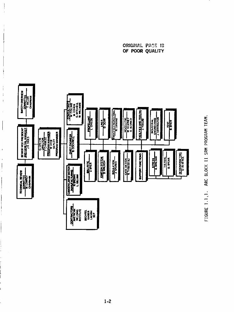
I.I ORGANIZATION
The Atlantic Research Corporation (ARC) Block II SRM team is shown in
Figure 1.1.1. Major support has been provided by the contractor and consultants shown.
The ARC team members identified are also further supported by Propulsion Division
Staff on a specific task basis.
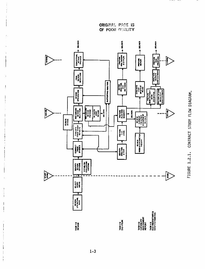
1.2 APPROACH
Interaction among the four contractual tasks is shown in Figure 1.2.l, Block II
SRM Contract Study Plan. The design studies task implements the primary program
objective of developing a Block II SRM design offering improved flight safety and reli-
ability. Sub-tasks shaded in Figure 1.2.1 have been completed. Review of SRM litera-
ture and detailed discussion with NASA personnel has identified deficiencies in the
Mission _I-L SRM and required improvements such as elimination of asbestos. Study
topics and criteria were selected based on the information. These are discussed in Sec-
tion 2.0.
A summary of the Preliminary Development and Validation (D&V) Plan is
shown in Section 4.0. The Capability Assessment Task was initiated early in the program
to provide support to the Design Concept Study Task in monolithic versus segmented
SRM handling, transportation, and facilities.
i-1
ORIGih_L PA_ 13
OF POOR QUALITY
" El3',', _I _[_i!l, , .an
IZ! x! lie
i i
I I
"1E
i_DI
m
i
eY
0
e_
e_
O
e_
.°
1-2
OF POOR _._,,_.ITY
0.._J
I--
0
m,,,'
i,
1-3
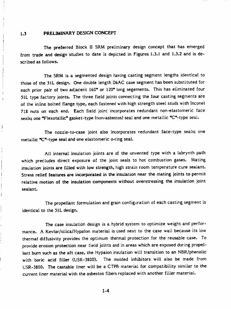
1.3 PRELIMINARY DESIGN CONCEPT
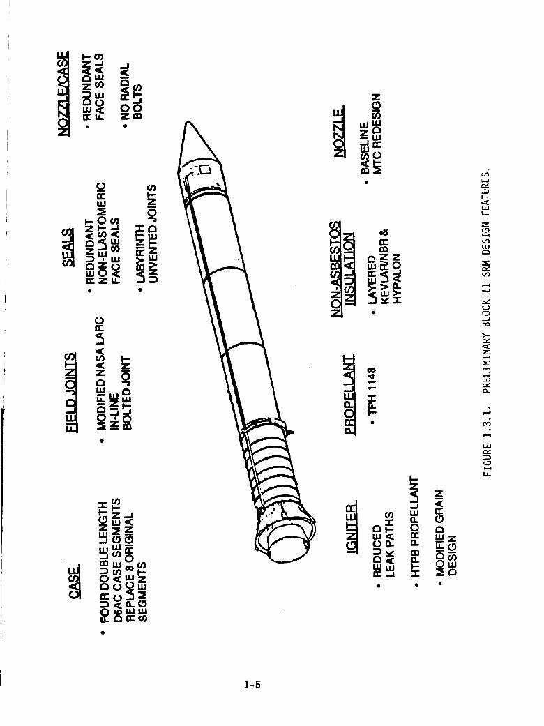
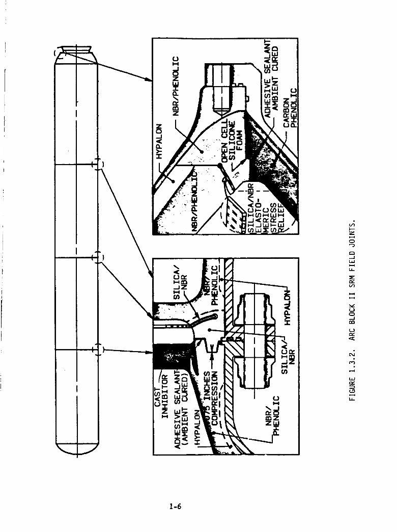
The preferred Block II SRM preliminary design concept that has emerged
from trade and design studies to date is depicted in Figures 1.3.1 and 1.3.2 and is de-
scribed as follows.
The SRM is a segmented design having casting segment lengths identical to
those of the 51L design. One double length D6AC case segment has been substituted for
each prior pair of two adjacent 160" or 120" long segements. This has eliminated four
51L type factory joints. The three field joints connecting the four casting segments are
of the inline bolted flange type, each fastened with high strength steel studs with Inconel
7lg nuts on each end. Each field joint incorporates redundant non-elastomeric face
sealsl one "Flexotallic w gasket-type (non-asbestos) seal and one metallic "C'-type seal.
The nozzle-to-case joint also incorporates redundant face-type sealsl one
metallic _"-type seal and one elastomeric o-ring seal.
All internal insulation joints are of the unvented type with a labrynth path
which precludes direct exposure of the joint seals to hot combustion gases. Mating
insulation joints are filled with low strength, high strain room temperature cure sealant.
Stress relief features are incorporated in the insulation near the mating joints to permit
relative motion of the insulation components without overstressing the insulation joint
sealant.
The propellant formulation and grain configuration of each casting segment is
identical to the 51L design.
The case insulation design is a hybrid system to optimize weight and perfor-
mance. A Kevlar/silicalHypalon material is used next to the case wall because its low
thermal diffusivity provides the optimum thermal protection for the reusable case. To
provide erosion protection near field joints and in areas which are exposed during propel-
lant burn such as the aft case, the Hypalon insulation will transition to an NBRlphenolic
with boric acid filler (USR-3$00). The molded inhibitors will also be made from
USR-3g00. The castable liner will be a CTPB material for compatibility similar to the
current liner material with the asbestos fibers replaced with another filler material.
I-4
Z
oIii
a. a. E._
L_J
l--"
LIJLI_
Z(3
=E
Vl
xl
C_,-J
>-a_
z
=E
..JL.IJ
O-
LIJr_
LI-
I-5
(')
(
Z
0
C:3--JLIJ
LI-
:Er,-V')
¢.)0iI
(J
W
_D
LI-
1-6
The nozzle configuration is basically the same as the 51L configuration
except certain materials have been changed to eliminate asbestos and/or to eliminate
pocket erosion problems. Also, internal joints have been reconfigured as needed to
provide redundant seals.
The preferred igniter design consists of an integral igniter adapter and case
with a bolt-on aft closure formed from 200 rnaraging steel. The igniter assembly is
insulated with Kevlar and silica-filled Hypalon and loaded with lg% aluminized HTP6
propellant. All joints are sealed using t-ring variants and metal c-rings.
1-7
2.0 TRADE STUDIES
Trade studies were conducted to select preferred Block II SRM design fea-
tures and materials in the following areas:
Design Approach (segmented vs. monolithic),
Motor case,
3oints and seals,
Non-asbestos insulation,
Propellant and liner,
Igniter,
Nozzle.
To support these trade studies, additional transporation, handling, and assem-
bly analyses were conducted for both the segmented and monolithic approaches.
Methodology
The following trade study methodology was established and followed to ensure
use of consistent and unbiased criteria in the ranking and evaluation of competing design
approaches.
Candidate designs were compared on the basis of relative reliability, cost,
and payload capability. Definitions of these ranking categories are as follows:
Reliability - the ability of the SRM to successfully function and propel the
shuttle through the intended trajectory without threatening the safety of the
flight crew.
Cos.._tt- Total life cycle cost, both recurring and non-recurring, to design,
develop, fabricate, transport, and assemble the SRMs needed to support 15
shuttle flights per year for lO years.
Pay!oad Capabilit]v - Number of pounds of payload that can be injected into
low earth orbit by the shuttle using the candidate SRMs.
2-1
Of the ranking categories, the most important by far is reliability. Weighting
factors were therefore assigned to each ranking category to account for their relative
importance. Reliability was assumed to be twice as important as the other two catego-
ries combined; hence, reliability was assigned a weighting factor of 0.63 (or 6396). Cost
and payload capability were considered to be approximately equal, hence, cost was
assigned a weighting factor of 0.20 (2096) and payload capability was assigned a weighting
factor of 0.15 (l 5%).
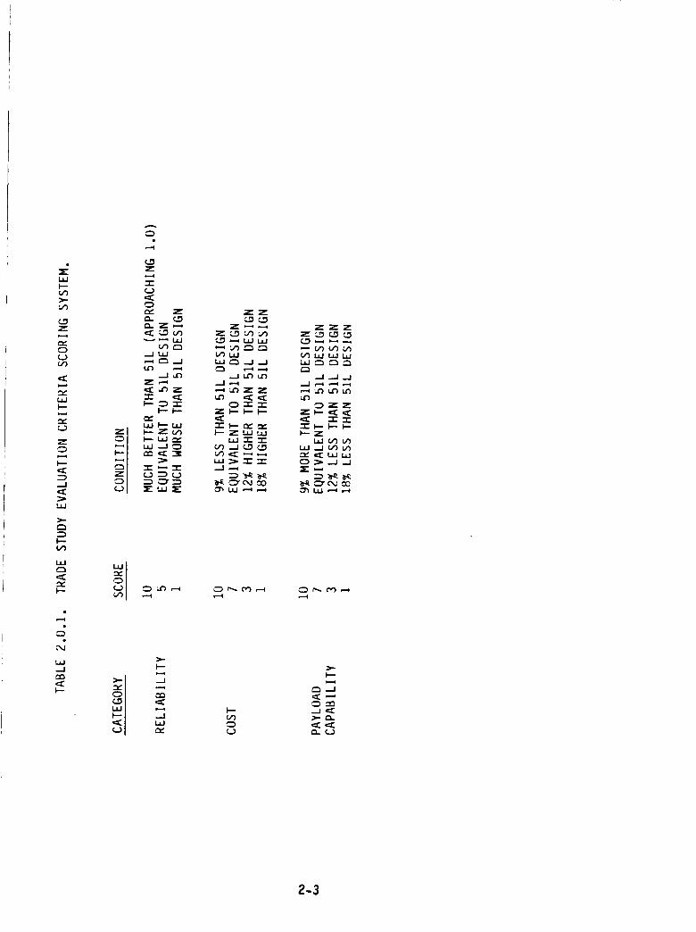
The next step was to devise criteria to assess the relative merit of competing
designs in each ranking category. For this purpose it was decided to use a scoring system
from I to 10, where 1 is worst and 10 is best. Specific criteria used is shown in
Table 2.0.1.
2.1
2.1.1
DESIGN APPROACH TRADE STUDY (updated 12/19/86)
CANDIDATE DESIGN APPROACHES
t
Two basic design approaches were considered. They were (1)segmented
design, having propellant grain segments identical to the Block I design, and (2) monolith-
ic design, having a single full length, one piece propellant grain. Two motor case seg-
ment variants were considered for each of these basic approaches. The first variant uses
1! case segments identical in length to the 11 Block I design case segments. The second
variant uses longer case segments as follows. The forward, forward center, and aft
center casting segments each use a one-piece, 320" long, cylindrical, weld-free case
segment in place of the two (160" each) cylindrical case segments used in the 6lock I
design. The aft casting segment uses a one-piece, 326" long, weld-free, cylindrical case
segment in place of the three (g6", 120", and 120") cylindrical case segments used in the
Block [ design. The segmented candidates were assumed to use 5I-L type factory joints
and new, improved field joints. The monolithic candidates were assumed to use 51-L
type factory joints throughout. The current P6AN propellant was assumed for all
candidates. Rationale for consideration of these candidates is as follows.
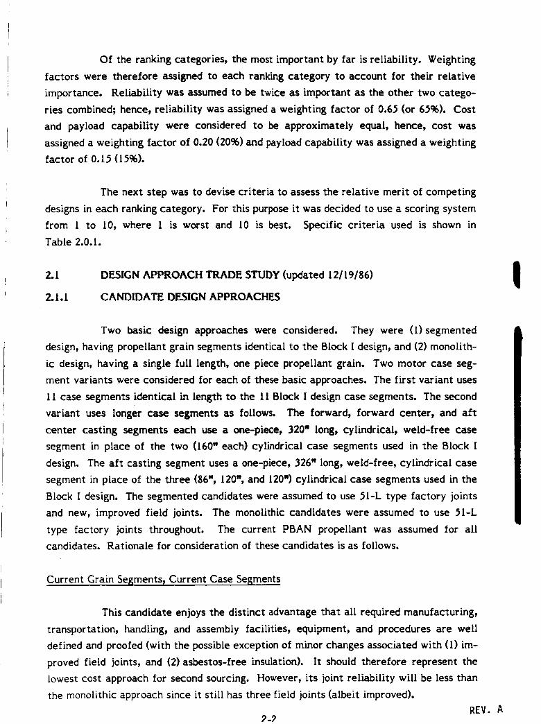
Current Grain Segments_ Current Case Sel_ments
This candidate enjoys the distinct advantage that all required manufacturing,
transportation, handling, and assembly facilities, equipment, and procedures are well
defined and proofed (with the possible exception of minor changes associated with (1) im-
proved field joints, and (2)asbestos-free insulation). It should therefore represent the
lowest cost approach for second sourcing. However, its joint reliability will be less than
the monolithic approach since it still has three field joints (albeit improved).
REV._._
A
I.l.I
_.-
Z
_s
tj
Z
-J
I---(,_
I--
.-I
L_
Z
_ I..,_ I,.ll.J
Z,--_
I--- I=-
_L,.I _-- U.II-- =_ m
_J -.J _
-e" ,-. "-r-
IE"' X
0 '.¢') ,.-_
--J
e_
..JL_
ZZ
Z_
_ZZ
C_
ZZZZ_
_ZZ
_Z
I---
2-3
Current Grain Segments - Longer Case Segments
Use of longer case segments would provide inert weight and assembly cost
benefits through elimination of five factory joints. The inert weight saved could then be
assigned to the fieldjointsto provide an increase in jointreliability,or conversely could
provide an attendant increase in payload weight capacity. The longer case segment
facilities/processesmust be developed, but all other required facilities/equipment/
procedures exist. [tshould represent the next lowest cost approach to second source, but
would stillhave whatever small residual unreliabilityis associated with the three im-
proved fieldjoints.
I
Monolithic Grain - Current Case Segments
The major advantage of the monolithic candidate is that joint reliabilty is
maximized since no field joints exist. It is also possible that payload weight advantages
could accrue due to reduced case insulation weight and increased propellant weight. Use
of current case segments to assemble the entire case prior to casting is justified since no
unreliability problems have been identified with factory joints. However, the monolithic
approach in general has several formidable disadvantages. These include (1)potential
reliability degradations in the propellant grain/case insulation/case bond areas arising
from the yet undeveloped fabrication/casting processes required, (2) safety issues associ-
ated with transporting such a large, propulsive SRM from the manufacturing facility to
the launch facility, (3)high cost to develop and procure the required manufacturing
facilities, (4)high cost of the D&V program needed to provide the required large data
base, and (5) high cost to develop and procure the equipment and facilities needed to
handle, transport, and assemble the monolithic SRM.
Monolithic Grain - Longer Case Segments
Advantages and disadvantages of this candidate are the same as the previous
monolithic candidate, except that a payload advantage would accrue due to reduction of
inert weight associated with elimination of five factory joints. IAdvantages and disadvantages of the candidate design approaches are shown
in Table 2.1. I.
2-4REV. A
C_
_--
L_JC_
m__--
b.J
Z
<.D
Z
LJJC_
.2
t%l
-J
-,m
¢_> -_
,_Z
_--Z _.>_
_t.LJ
,,L_J
_-) r'v,
¢.._ P',
I--"
Z
Z
I_D
L_J_--
Z
_D! LtJ
ZbJ_
N_
_ _Z
_ _Z_
I
L._Jt_J
L_--"
_J
i,i
Z
..I
m_
i,
I---O.LIJ(.JXLIJ
I
V1
Z
"...m
F--Z
L_Jm_
<.>
°.
Z _
_Z _ _ _
_Z _ _ _
_ _ Z_ Z_
L_J
m_,,t
Z0
t/>
Z
Z_L_J_J
I
N
_Z _
Z_ _
Z _ _
_ZO _Z__Z _Z
L_I "_-__.0 _..J
-J ,:_
_..J
L_J_J
L_j --_ --_Z
_, m_-_O _
_t_J Z,:_Z
_Z
_Z
X Z_
Z_
Z_ _
_Z
_Z
_0 _Z
F--Z
Z<-_
m_
<..>,=_
-r-
_--_Z._J_J
Z_
_" ¢.>
2-5
if)
==
t4J
Z
Z0(.3
C_4
_J..J
mm
L4J
Z
t_JC.3Z
(.3
C_
L.I..
•=C I'--
:::_ C,").::CZ"_'0
I--Z
,=C V')
r,__ .=C r'_
I-- I--- Z_--0 Z m,-,4..=.I I._I I--.Om*'ZZ_.,O0_C.3
-l-l i
W
.. I=--(.3Z
>-
"_-0(.0_-
!
N
(.3
Z
_--ZL_J
O.C3.-JL_J
t_J
X
!
Z
'--3
-JL_J
L4-
Z
I
Z
m_
..J0Z
0
L_J
aDZ
l--
F- ,--,c_ --im
(_) ,--,=ll
_Z
l---_"
i"l"lll..J
mm
.lll=l=l
I'-"Z
l--"Zl=IJ
C,m
L.IJ
Z
._.1
I--
I--
ZZ
_Z
t_J
_-_Z
L_._--
L_JZ
(._._Z_
Z_-__--.=_ _-_.=J *.d
nn._
O..m-
(.3_J
_- L4J
0
(..)Mmm
..J
Z
Z
=J.--J
C3O_
t4J
W
(.3Z
Z
k_J(.0
..J
0
t4J_J
_J
OOL_J
P--O
t_J(J
C:_U.
C_._J l=-__-r"
L_J
e'_3_Jtl) r'_
_Z(..3 e'_ --_Z_JO
Z _
Z__Z
_ OZ
Z_Z _
_Z_ _
_ Z_
_ _Z_Z _
Z-6
2.1.2 DISCUSSION OF MONOLITHIC SRM DESIGN ISSUES
Issues bearing on the ranking criteria of flight reliability, payload capacity,
and cost were raised in several areas for the monolithic design approach and are ad-
dressed in the following paragraphs.
Design Integrity Issues
Ballistic performance and grain design studies were conducted to verify that
the thrust vs. time performance delivered by the existing segmented design could be
duplicated using a one piece monolithic grain design. These analyses identified two
monolithic grain designs capable of duplicating the existing thrust-time trace- one
having slots at the head end of the motor and one having slots at the nozzle end of the
motor.
Abbreviated structural analyses were conducted to assess the stress-strain
state of the monolithic grains identified by the ballistic design studies. These analyses
indicated acceptable stress-strain conditions would exist in the grain bore, slot, slot
termination, and grain end termination areas over the specified environmental and opera-
tional ranges.
Manufacturing Issues
Manufacturing trade studies were performed to determine the most reliable
and cost efficient method of production for a one-piece, monolithic SRM grain with
current length or longer case segments. Where possible, manufacturing procedures
similar to those for the SRM Block I segmented design were selected. However, special
procedures, equipment and facilities will be required in many circumstances to produce a
monolithic grain to the specified configuration.
Case insulation integrity may be affected. Since the insulation layup takes
place once the case segment assembly is complete, the problem of handling a very long
steel case is imposed. It is unknown whether or not the rubber can be kept at a constant
temperature as it is fed into the length of the motor. Also, an extremely large autoclave
is required for the vulcanization process, not to mention the size of the vacuum bag.
2-7
Problems encountered with similar applications of large vacuum bags include premature
deflation of the bags which tends to ruin the insulation.
A 116-foot casting-segment length causes concern over the lining and propel-
lant casting operations. A sling-lining technique is optimum for large-diameter cases
regardless of segment lengthl however, a significant redesign of the liner applicator will
be required in order to line the full length of the case in one continuous operation.
Similarly, due to the long propellant drop height for the monolithic grain configuration,
an alternate propellant casting method must be developed. The tooling required for
casting will be more complex and costly than that currently used to cast a Block I SRM
segment. Large, heavy-duty cranes and equipment are needed, as well as a IS-story deep
pit and IS-story high building structure.
The new casting method envisioned utilizes a segmented bayonet which is
lowered into the case for casting. Bayonet segments are withdrawn from the case as the
propellant level rises. Although the propellant drop height problem is alleviated, the
casting method still involves working with tooling at great heights above the bottom of
the casting pit. This poses serious safety issues.
Major uncertainties exist relative to liner, propellant and bond integrity of
the one-piece, monolithic grain configuration. Maximum propellant fill time, consistent
with current casting flow rates for the Block l SRM segments, is roughly 5 1/2 days. This
casting fill time is greater than the liner and propellant cure times. Therefore, propel-
lant at the bottom or forward section of the SRM grain will be fully cured before casting
at the top or aft section is complete. Effects of a cure gradient on the propellant bond
and bulk properties are not entirely understood at this time. The effect of hydrostatic
pressure gradient might also affect propellant properties.
Mandrel insertion and extraction in a monolithic grain will compromise manu-
facturing safety and reliability factors, as well as cost. Trade studies indicate that a
segmented mandrel is most suitable for a single-piece monolithic grain. The mandrel
would consist of a segmented inner core, which is pre-assembled prior to insertion into
the case, and segmented fins, which are pre-assembled, inserted and attached to the
inner core. Due to the size of the aft case opening, the fins must be lowered through the
clearance between the inner core and case, and attached to the inner core within the
case. This task is challenging regardless of slot location, aft or forward. Core popping
2-8
also proves to be somewhat difficult in a monolithic grain for several reasons. Mandrel
extraction is stressful to the mandrel tooling itself due to the adhesive forces between
the core and propellant. Hydraulic systems both at the top and bottom of the casting pit
are required to provide force to initially release the mandrel. An intermediate system
near the aft section is also necessary to remove and detach the extracted mandrel sec-
tions. Drop height is still a concern as heavy-duty cranes and large equipment are oper-
ated 116 feet above the bottom of the casting pit.
Other manufacturing processes which involve special procedures for the one-
piece design include breakover, x-ray and grain finishing. As noted in other operations,
the size and weight of the monolithic SRM greatly hinder the processing and handling
flow. The equipment required to manage such a motor is not easily maneuverable.
Although the number of handling steps is greatly reduced for a monolithic SRM, the level
of difficulty assigned to each operation is significantly increased. This has direct bearing
on manufacturing safety and reliability. Should problems occur during processing the
motor or a defect detected which may cause rejection by quality control, an entire
1.1 million pound motor may be lost. This is expected to create tremendous pressure on
program personnel to accept or repair a marginal motor in order to avoid schedule slip-
page or to take a multimillion dollar loss.
Handling Issues
The larger physical dimensions and higher weight of the monolithic motor
relative to the segmented motor requires much larger and sturdier construction of hand-
ling equipment. This results in higher costs of handling equipment, tooling and facili-
ties. The cost multiple of monolithic vs. segmented motor handling is much more than
the respective weight multiple. A monolithic motor will require handling equipment and
facilities at KSC that do not currently exist. A multimillion dollar hoisting facility
would be required. The VAB currently handles the KSC hoisting requirements for the
segmented motor but does not have the capability to handle a monolithic motor.
There are also safety concerns involved in handling a monolithic motor. For
example, when the motor is being lifted out of the casting pit it will be suspended 13 to
It stories above the bottom of the pit in the worst case. An error or accident at this
point could be catastrophic.
2-9
Transportation Issues
Transportation of a monolothic motor from Camden, Arkansas to KSC pre-
sents serious problems due to its size and weight. Rail and barge transport were the two
modes considered for the shipment of the motors. Of these two modes, barge transport
was the only one deemed suitable for the monolithic motor. Shipping by rail was found to
be unsuitable for the following reasons;
The length of the motors makes curves, trackside obstacles, rail yardsand adjacent rail lines difficult to negotitate and hazardous to cargo.
The weight would require some rails, rail beds and bridges to be forti-fied. This is a very expensive prospect.
The many hazards that would be encountered over the route are reasonfor concern because of the propulsive nature of the monolithic motors,
There are many regulatory obstacles dealing with size of cargo, itsweight, the custom-built railcars and its hazardous properties.
The cost of the railcars is an estimated $6 million each. At least 20would be required.
Waterborne transport is the only other candidate. This mode would, however,
require a sizable capital expenditure for:
Camden River dry dock loader
LC-39 dry dock conversion (KSC)
Rail connection at Camden
Rail connection at LC-39 (KSC)
1500 ton river barge with railcar capacity
1000 ton railcar
Rail extension to KSC SRM TS
There is still a question of safety regarding the propulsive nature of the
monolithic motor. The estimated potential range of the motor is 300 to 500 miles in its
shipping configuration, where the igniter and the nozzle have not been installed and both
attach ports are fully open.
2-I0
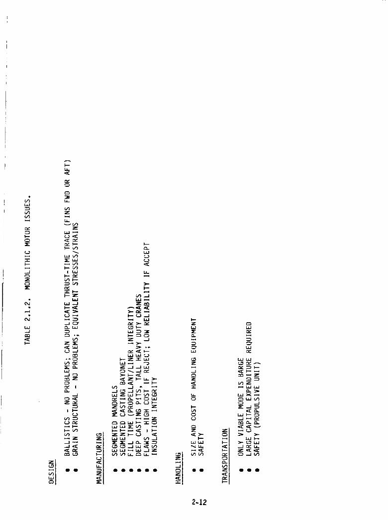
Monolithic 5RMissuesare summarized in Table 2.1.2.
2.1,3 RELIABILITY ASSESSMENT
The most important single attribute of the Block II SRM is its reliability. All
of the candidate design approach concepts will provide higher reliability than the _lL
design through improvement or elimination of field joints. For purposes of comparison,
on a scale of I to l0 with l0 being best, the 51L configuration was assigned a reliability
ranking value of _.
The segmented designs incorporate field joints consisting of in-line bolted
joints with redundant, non-elastomeric, non-pressure actuated face seals. Joint gap
opening at the seal locations due to pressurization is practically non-existent. Non-
vented labrynth insulation joints have also been incorporated at each field joint to pre-
clude exposure of the seals to hot combustion gases. No other SRM case-liner-insulation-
propellant features have been changed from the _IL configuration except for substitution
of non-asbestos insulation. Since the demonstrated reliable features of the case/grain
assembly have been retained, and the reliability of the field joints has been dramatically
improved, the segmented designs were assigned a reliability ranking value of g.g
The monolithic design candidates have the advantage of having no field joints
at allI thus_ they represent an ultimate I0 in joint reliability. However, serious uncer-
tainties exist in other areas. Due to the long fill time, propellant near the head end of
the motor will be completely cured before casting is complete. This cure gradient, along
with the varying hydrostatic pressure caused by the propellant head, could adversely
affect propellant physical and bond integrity. Further, the propellant liner near the top
of the motor (late in the fill) will be completely cured before the uncured propellant is
cast onto the liner. This could adversely affect bond integrity.
Due to the long, confined interior of a monolithic motor, increased difficul-
ties will be experienced in applying insulation and liner to the motor interior. This could
manifest itself in reduced reliability of the insulation and liner.
Defects detected by NDT of cast motors can potentially lead to reduced
reliability of monolithic motors. This arises from the fact that a rejectable defect could
cause loss of an entire monolithic motor but loss of only one casting segment of a
2-11
JLI.I
C/')U'3
r,,,"
I--C3
C..)
"n-l-'-
--J0Z0X
L.I.J--Jr_
I--"
(.OZ
(..3
1,4-
I,--
Z
._IC_I.LIZ
rml--Z_
l.,ulU.lI-= I'--ZZ
U=l I._
Z_
Z
Z_
Z_
.__
_Z_
_Z
I-.ZI=_
C3"L4J
Z
Z
-I-
0
I'-
0
Z<>-
I---_JL_J
2-12
L4.JC_
ILlm_
t4J t4J
O_ "_ _--.
mm_ z
_Z
LtJ X _.-_
_" ..J _
==0 Q 0
segmented motor. It can therefore be expected that heavier pressure will exist for
program personnel to accept or repair marginal conditions in the case of monolithic
motors, thereby degrading reliability.
Because of these concerns, even though joint reliability is maximized, overall
reliability of a monolithic motor was assigned a reliability ranking value of 7.4
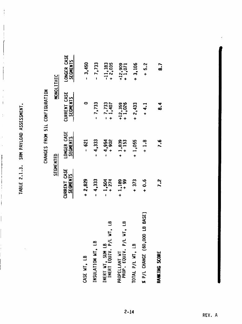
2.1.4 PAYLOAD CAPABILITY ASSESSMENT
The design concept candidates were assessed for differences in payload
capability resulting from differing SRM inert weights and propellant weights. The 51L
configuration was assumed to be the baseline, capable of carrying a 60,000 lb. payload
into low earth orbit. Payload influence coefficients were assumed to be:
APL -11b = -0.182 Ib payload(1) aTi = +5.5 Ib Ib $RM inerts
(2) APL +11baTp +12.0 Ib
Ib payload= +0.083 Ib SRM propellant
The results of this assessmentp shown in Table 2.1.3, show that payload capa-
bility change ranges from -0.896 to +0.3% for the segmented candidates, and ranges from
+3.1% to +4.2% for the monolithic candidates. The better payload performance of the
monolithic candidates is largely due to the extra propellant assumed to bridge the gaps
between original grain segments. However, a significant portion of the added propellant
would have to be cut out in the form of longer longitudinal slots in order to tailor to the
correct thrust-time trace shape, which is expected to largely negate the assumed propel-
lant weight increase.
I
The ranking scores shown in Table 2.1.3 were assigned in accordance with the
criteria presented in Section 2.0.
2-13
REV. A
zt,.i,JX
I,,iJ
,-.,,i
,_l
el:r,l
l,,4,,,,,-4
I.iJ,,-.I
1-,,,-
0 -_
..J
u,.
_ LLJ_"
I"-
_ _ _ _ +J 0 0 ÷ ++ +
e
0 0 ÷ 4--I- ÷
es e_
o J + +
II II
@,,i
+ I
or,, o00_ r,. •
•-_+ ,'_ + 4-
i +
o_
143
r,,,
elm-J (13
..I
...I Z
w
•_: :Z
A
ill
el:133 (13.--I .--I
en
.--I --J
O. (X. e,_
_' I--0" z
"_1-- .-J o.. ¢_
2-14 REV. A
2. l.S COST ASSESSMENT
Large cost differences were anticipated between segmented and monolithic
approaches in the areas of manufacturing, handling, transportation, and assembly.
Significant differences in both recurring and non-recurring costs were expected. It was
therefore decided that relative cost rankings should be based on total Life Cycle Cost
(LCC) for the postulated mission model of IS flights per year for l0 years.
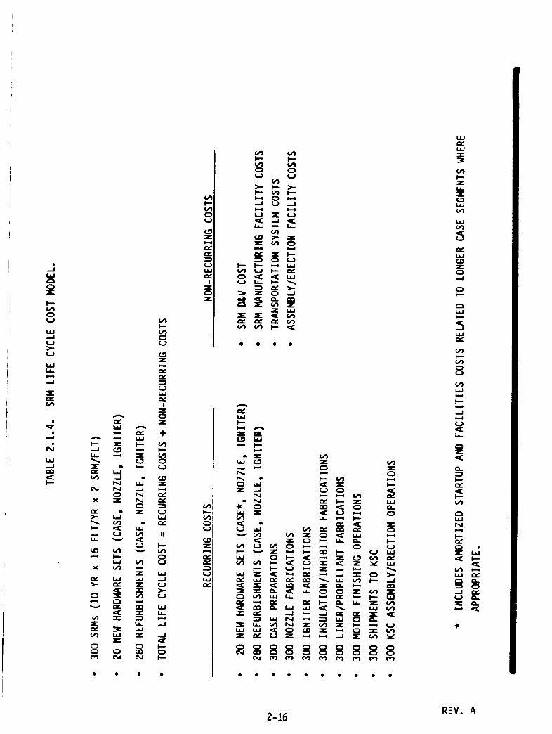
SRM Life Cycle Cost Model
Considering recurring costs, a total of 300 SRMs is needed for the 15 flights
per year, 10-year mission scenario. Based on the requirement for 19 reuses, and con-
sidering attrition, it was assumed that 20 new sets of SRM cases, nozzle metal parts, and
igniter metal parts would be required. It therefore follows that 280 refurbishments of
the SRM cases, nozzle metal parts, and igniter metal parts would be required.
Non-recurring costs include D&V costs, SRM manufacturing facility costs,
transportation system costs, and KSC assembly/erection facility system costs.
costs.
Total Life Cycle Cost is defined as the sum of recurring and non-recurring
The SRM Life Cycle Cost model is summarized in Table 2. l.g.
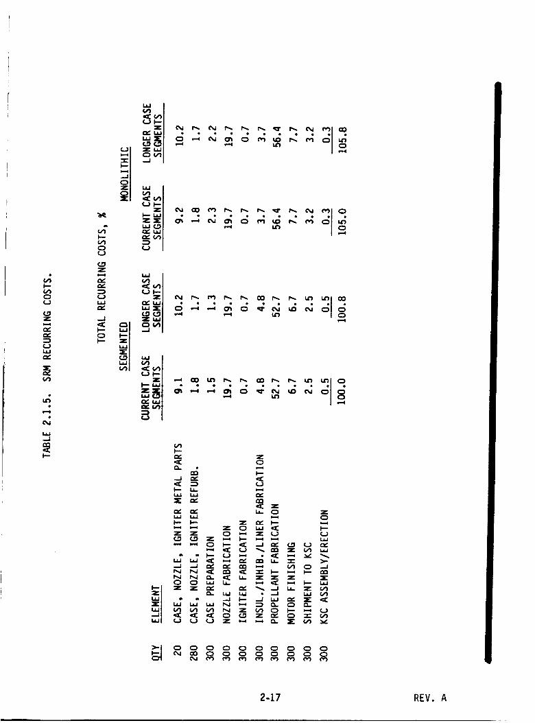
Recurring Costs
Normalized recurring cost estimates for each candidate design approach are
summarized in Table 2.1.5. Unit costs were estimated for the discrete elements indicat-
ed, multiplied by the number of elements required, and summed to obtain the total
recurring costs. The segmented candidate consisting of current case segment lengths and
current casting segment lengths was chosen as the baseline and its total cost was normal-
ized to I00%. All other costs were then normalized to the baseline cost. Unit costs of
the longer case segment designs include amortized costs of added facilities and startup
activities required to produce the longer case segments.I
2-15 REV. A
Ji.i
v)(3(J
w_J(.J>.-u
taJi,
:Er,,
_J
,:E
P:,
U
¢v,I
z
u _v)
Ii _ I--
-J ¢J ..1
_ X U
u.. _- u_
C._ _.. zz _
z i'-
• • • •
wI--
A
Z Q_W
,..., _--
* Z
z ..I
. _4
z __ z_ Q
_ z _
_ z
u _ Q
uu1-- v Z _ I-- r_ I--
I-- I--" U t-_ Z -.I _Z _ .--* _g _-_ --,I :3:: (3 >.-
"_ "_ _- _[: _ _ _ z _ X
•--_ L_ N _ _ _J
L_ _ _C _ _ Z *.-* (_ =Z=Z _ U Z _ ,-* .,J -Jr" V1 '_'
° 88888888(M(M ¢vl (_ ¢v_ ¢vt t_ r_ evl (','7
wr_L_
_e
F--z
w
r_w
z
.J
Q
e_
w
U
w
F-
z,q:
Q..
,v
I--
r_
Q_
_j ,._
2-16 REV. A
(J
(._zi--i
--z(,.)l,i
vl
1.1.1_.1
F--
0
la'! ,-_ ,--4 _
u
p-
°.(_1
vl
P" z
.j ,Y
1.1 i,i cl_X _" cz2
I.z.I la.I
Z z (3 _ Z U
Z0
(.3i,i
laJ
0 (3 la..I la. _ _ ,--_ I-- la.Iz z _" _'_ _,_ ._ ta. z (v_
¢,4 _ N Z _ (:3 In _--_ U
0 (3 0 (_ (:3 0 (3 0 0 0(M CO 0 0 0 0 0 (3 (3 0
2-17 REV. A
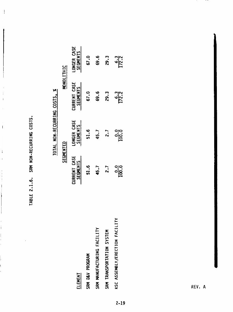
Non-recurrinR Costs
Normalized non-recurring costs are summarized in Table 2.1.6 for the candi-
date design concepts. These costs have also been normalized such that 10096 represents
the total non-recurring cost of the baseline candidate.
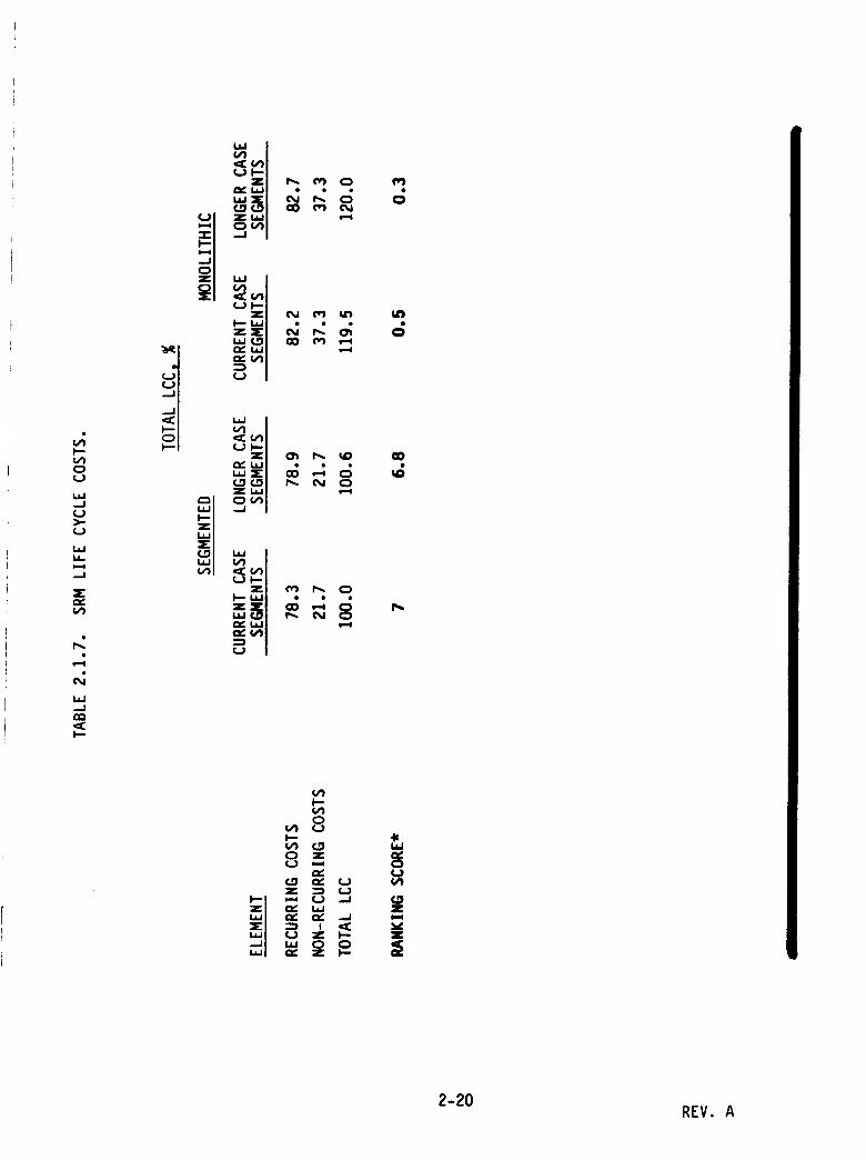
Total Life Cycle Costs
Normalized total Life Cycle Costs are summarized in Table 2.1.7. Again, all
costs have been normalized such that 10096 represents the total Life Cycle Cost of the
baseline candidate.
The cost ranking system discussed in Section 2.0 was used to compute cost
rating scores. The segmented design using current case segments was assigned a rating
score of seven since its total LCC is representative of the current configuration.
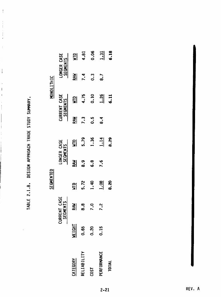
2.1.6 RANKING AND SELECTION OF PREFERRED DESIGN APPROACH
Table 2.1.8 summarizes the results of the Design Approach Trade Study.
Rating scores from I to 10 (10=best) were derived for each candidate in the ranking
criteria categories of reliability, costt and performance as discussed in the preceding
sections. These scores were multiplied by the appropriate weighting factors shown to
obtain weighted scores. The weighted scores were then summed to obtain an overall
score. As shown, the segmented design having longer case segments and current length
casting segments had the highest score of all the candidates, and was therefore chosen as
the preferred design concept approach.
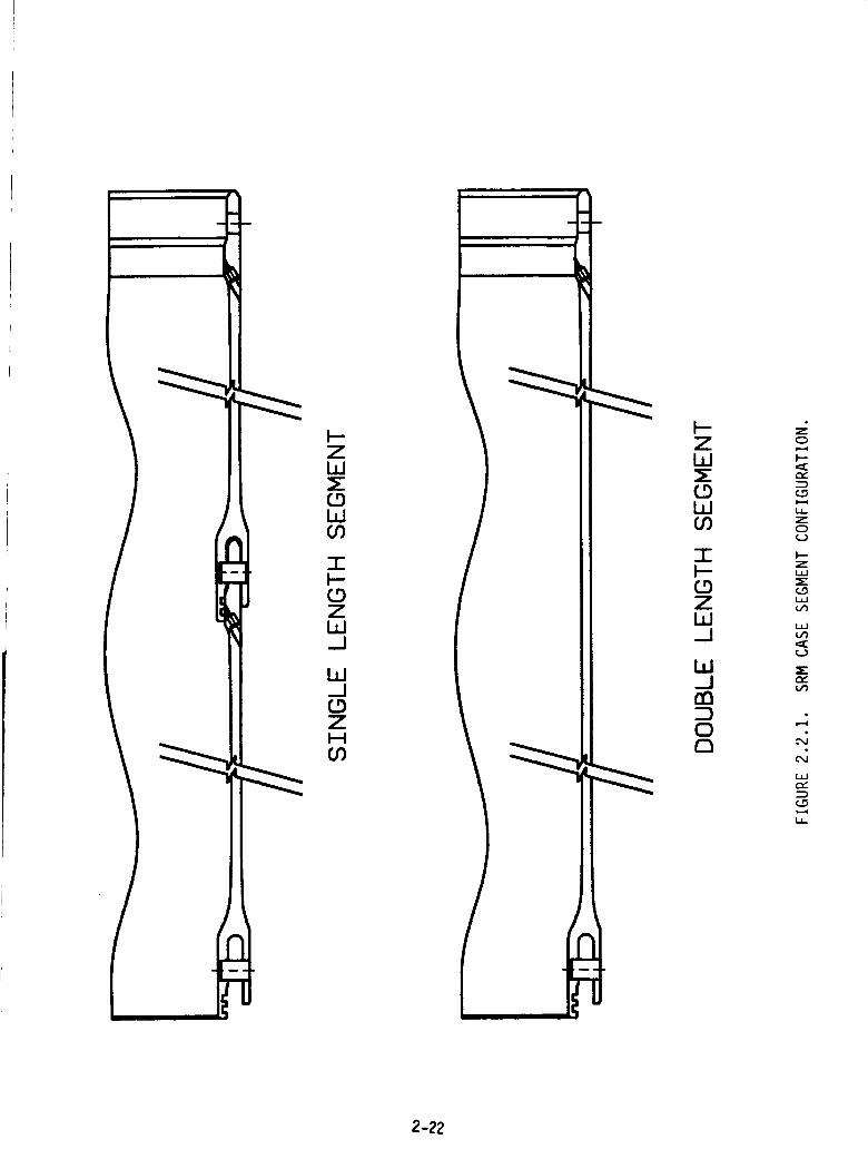
2.2 SRM MOTOR CASE TRADE STUDY
The NASA space shuttle solid rocket motor (SRM) case was evaluated for the
feasibility of fabricating casting segments from current ()I-L type) length case segments
or from one piece 320 R and 326 w long case segments. In this study, materials and
processes were identified that could be used in either case configuration and a trade
study was performed to define which material and which configuration was best suited
for the rocket motor case. The configurations assessed are shown in Figure 2.2.1. The
existing factory joint configuration made from two 160 n case segments will be referred
REV. A2-18
I--
C_
z
n_
I
z
w_J
_ _ v REV. A
2-19
I.i.I...I
f,j
LdLLl,,,w
._I
,.c
Ld.,d
"_ U")
'_"C,rJ
f_
0
I..-
0(..)
0
c__ z I--u.i Q ¢_
C._X
Z
2-20 REV. A
rv.
's-
u
o
z
F--
7=_, _i_._.
u
°i
z_-
,',"(s).
-_ 8 _
2-21 REV. A
N-ZW5-CDWCO
TF-CDZWd
W.J_DZ
CO
ZW
WCO
T
ZW_J
W_Jnn
00
0M
r_
L_
cD
zW
W
L_r_
LL
2-22
to as the single length configuration while the one piece 320" long case segment config-
uration will be named the double length configuration.
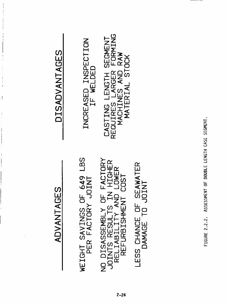
The double length case configuration is a viable concept for use in current
casting segments. This length case can be fabricated as a monolithic structure or as a
welded two piece case. The double length case would require no mechanical insulated
joint or pressure seal and would focus the case integrity on a circumferential weld or on
parent material properties for a monolithic double length case. The potential weight
savings per joint would result in a weight savings of 690 Ibs for each joint. This would
allow for either increased payload or reallocation of weight to another area of the rocket
motor assembly. The case could be proof tested to verify weld integrity and magnetic
particle inspected or fluorescent penetrant inspected to examine the weld zone or parent
material for cracking. The elimination of a mechanical joint would reduce the chance of
saltwater corrosion and the possibility of stress corrosion cracking. The double length
segment would eliminate potential rework associated with a single segment, mechanical-
ly pinned joint. The various [eatures of the double length case configuration are ad-
dressed in Figure 2.2.2.
The current case material, D6AC, was originally selected for its superior
strength in a non-welded configuration. The heat treatment level was controlled below
the maximum strength level of the material to improve its toughness. At the time of
selection, D6AC was a widely used rocket motor case material and possessed a large
experience data base. The choice was good. Several other materials have emerged as
dependable material candidates since the initial case selection and the trade off between
a single length case segment and a double length case segment. These additional vari-
ables mandate a new investigation to determine the best material choices when applied
to different manufacturing methods. Material properties and behavior combined with
manufacturing process considerations will trade off to create the best case material and
configuration.
The candidate materials are shown in Figure 2.2.3. Each material shown has
production experience and is currently in inventory. The materials vary in ultimate
tensile strength from 200,000 psi to 260,000 psi and can be downgraded in tensile
strength to improve toughness. The chemical composition of these materials is shown in
Figure 2.2.4. Several missile systems that use these steels are shown in Figure 2.2.5.
2-23 REV. A
00W
<b-Z<
D
O9I--4
D
00W
<
Z<
(3<
Z Z zO W H
b- (_9 ',e'
m co oo..otom
H_I
(/)U_ Z<H
n.o mS<Z
tOnnd
_Z_H
OLL--JO
>-00n___90Z_HO><<LL
n,_WIn(_9H
W 0 o_Z _
r_W_--
<ZWH
0_O-3
LLOO
F--WOWZ_D
T_O<
0ODODW
ZL_J
L_JVI
"-1-
ZL_J-.J
ILl--J
0
L_.0
Z
C/I
L_
N
N
L_
2-24
O<,,Or-_
CDZI--I
CO,,(
OLOO,I
O _"O _ OI'O IV) OIV) _ IV)
GOZH
LD
n-,<
OOCU
r_
I--
I--
r-_
Z
C.)
1.4.1
r_
,,4O,.I
0,i
r,,,"
I.L
2-25
<
Oi
OD
FMZW co
C.3r-
..j I
_-4 (_3
WF-
Z<H
n_W
<
OL[')--0
O
• IcO
I I
Oo I'0 OO0_ • P00J
Ob0OO 00 O_0P_ __ . ,
O1_3 IOO IOI"3- n l'0Ol .
i
O0 O00_,.0 i aO_O
QO('%J 1"3o0',q'- ',_" 0 ',_"r")
00
,,0r'_
ZI-'4(_9
n,
IO
O _fO P9
O
tO• I
cO
0 tO-- I 0
OO O IOOPg0J • "_P9
O10 O100_0 cO 0,,0
O0 100
OlO
u 00'_
LO_) OLOa0_0 i 0_0
P000 _00
ZI--4
<r_
O_0 O OP9 kO O
@LL
W(_)Z
<_n
m
Z
0
0
0
(._
(_)
ILl
..d
2-26
+ 00000O00LO000_i In _ 00_11"-
im im p
00000000000000_
_--0------_
0o0n
P
m
0_D
000
IP
0_
H_HHW_ X
_0< _ WZ_ _Z___W Z___O HHI<_<_I P
TOCDZH_
LL_J
n_W Z0 0Z (_9
_--onr(/)_n
n_Oh-
0_WZW_D
(..9
WEL
O
W
!
_D0n
,y
I---
n_w0_ww
w0
W13_
O
4OO0
C_v
r_O
-r"
.J
L_
N
N
ILl
r_
__0
LL
(..)
_DO
(_9ZH_(_91
n-W0
I'D
0
_000
2-27
Most of these missile systems have welded construction in the rocket motor cases. Many
have thin wall sections unlike the SRM case but the flaw sizes become more critical at
the thinner wall sections.
The major criteria for analyzing suitability of a material for the SRM case
application are tensile strength, strength to density ratio, overall body stiffness, fracture
toughness, susceptability to stress corrosion cracking and the many manufacturing and
handling considerations associated with each material. High tensile strength enables
designing to thinner wall sections or combining lower strength with increased toughness
for a given material. The various room temperature properties are tabulated in
Figure 2.2.6 at representative strength levels. The stiffness of the rocket motor case is
directly affected by the material's modulus of elasticity, the diameter and wall thickness
of the case wall and the number of mechanically jointed case segments. By trading wall
thickness, joint quantities and material properties, an optimum case material can be
selected. Integral to this discussion, the effects of fracture mechanics must be incorpo-
rated to determine the effects of toughness on tensile strength and wail thickness and
the capability to manufacture a case in the selected material. Corrosion effects play an
important role in material selection because they affect material tensile strength and
wall thickness required to satisfy damage tolerant properties. Selected damage tolerant
properties of the candidate materials is shown in Figure 2.2.7.
Manufacture of the case segments in the single length and double length
configurations are dependent on the material selected and the processes that are avail-
able to fabricate the desired form. Maraging steels are suitable for shear spinning over
long lengths because they have little impact on the heat treatment facilities and are less
likely to distort during heat treatment. Conversely, quench hardenable steels require
close control over the heat treatment process and heat treatment of such a large length
with low distortion may be impractical. Several large metal structure fabricators were
contacted and asked to participate in a manufacturing study to assess the materials and
forming processes that could be implemented in a SRM case. These contractors were
asked to evaluate their capability to produce a case of the single and double length size
and the relative risks associated with each process. These contractors are listed in
Figure 2.2.8. Some observations about the various materials were made relative to
existing technology and expertise and the following generalizations were made:
Q
_Z>-_w_-rv_
--'mz
wm
pt _.1 i,-tm_mzalgw Q'-."
_J _Zi,i _0
(/)
WI_-._
IgZ
_JI--•--_if)
>-0.J_J<
o° o° oo o° o o
r-- o_ _ r-- _0
_W
u,I
w if)
o _ _ __ _ o _('.:(M C_ C_ C_J -- --
0 _'_ 0 0 0 _'_-- If) CO _0 O_ O_O_ O_ O_ O_ O_ --
E_0 tt
0 0 _" 0 '5"(.D
0 _ 0 _ > <C_l (ll 0 I'0 O
(J U rO E__0
-Ic
ILl
i___,.o
_..
._1,<
z,<
1.61
I--,<
L;.II--
00
N
N
C_
2-29
'_ O0
PO
0
0 0,¢
_D
PO
00 0
CU
0rO!
H
ZZ
<.._n_I--(I)
WWZZ_
_JHO. 7"
a.
0
L_
o
L_
WF-<_Ja.
0
Wp-
0
0PO
WI--
._1
0
Wl--
_Jn
0
0
bJI--<_IO.
0
+"IZ,<-1-
Zt5
u_
:k-P- 0m
_.Jzbd
bdb.
W WF-- n,
.3
L_
CdLuJel_0
L_J
L_
0I--
L;J_Dc_
N
N
D
_D
0
_J
00Od
_J
0
O_
_J
00
0>
00PO,,4.
tJ<_D0
2-30
<><<
Z< Or) ,.)-- > :5"0O ,. -T I
_n"<O 0<H "WW_
Z _ _ n" H CO rn
O Z _- rY n (1))_ (Y) Z) Z /Z >-,_ < _,_ W W-I" < O"Y' /nnOO n Z)_ O (/) O
p ql_
W__Jn-W_j_5-Hnn
/LL
<
OO<
ZWa.
wF--
H
ZH
(_gXZO00HO'_"O ..J r_"_IHO (,0W33 33 • W
,_Z O ZZ OZO< _" rw H I--O(_)Hll I Z _)-40 (Y) (/) O O n"
n,w
(_9 z_z ww H (/)OHb-dn,' _ <Z WF- < b-O
(J WHW
Z _ W_WCO _n,'_ Z
ZO_n, (_) T O HI-- __.O n" n WLL< I--W nnl-- _ nl--)_ Z-F Z b_Z_n (I)_" ,_I_,_ Z) ,_I_bl W (I_O ,_ WI-I I W
2-31
,.'F
C_
,,<
C_
C,U
C_
r,."_D_D
Maraging steels offered lower distortion due to the heat treatmentcycle_
• Quench hardenable steels were slightly easier to machine;
• Maraging steels were simpler to heat treat;
Welding was easily performed on maraging steel. Welding carbon steelswas more difficult.
Materials could be obtained in various forms as shown in Figure 2.2.9. Large
forgings, similar to the existing forgings used for the single case segment, could be roll
forged into a ring in preparation for further reduction in area at subsequent processing
stages. The same forging could be upset and spin forged against a roller die to net the
same case. Initial formation of the cylindrical stock could be performed by a cylindrical
casting of the low alloy steels. D6AC and the maraging steels would not be suitable for
this process since a vacuum arc remelt is required for these alloys and alloy segregation
may occur in the maraging steel. Rolled and welded sheet stock, the mainstay of the
aerospace rocket motor industry, is the final form. A thicker rolled and welded cylinder
could be manufactured and subsequent forming operations could be employed to reduce
the wall thickness of the case. This process would also planish the weld area and de-
crease weld effects at the longitudinal seam. The candidate materials and processes are
tabulated in Figure 2.2.10 and show the relation of material to process.
The heat treatments for the material candidates fall into two categories:
quench and temper for D6AC, 43#0, #330V and 300M and maraging for 200 and 2S0
maraging steel. A typical heat treatment cycle is shown in Figure 2.2.ll. The major
differences between the two types of material heat treat cycles are the number of heat
treatment steps and the severity of temperature fluctuation. In the quench hardenable
steels, several steps are necessary to obtain final physical properties. During the pro-
cess, the materials are subjected to severe changes in temperature over short time
periods which are necessary to harden the materials but these temperature shocks have a
tendency to distort the motor case. The large size of the SRM case is nonconducive to
maintaining roundness and straightness during the severe heat treat cycles. With marag-
ing steels, only two steps are required to heat treat the materials to final strength
levels. The aging process requires a low temperature and a short time to obtain the final
physical properties. An intermediate working process is possible by forming the material
2-32
CDZH
COn_0b_
_J_J0
ZH
(._9n_0b_
(.5 ZZ Z H ZI--I H PI I--!(_9 n, _ I--
0in_ C.,1
ZHI--CO<C_l
.._l<
I.!_Hn_
Zw0 W
W
_0
E_JW
C_Z<
d...I0
Eo
-.I
I--
m,1
oo
or;
N
N
L_Jm-"
LI-
2-33
ZI--t
Or_
I
001"3
0
>
0I'01'0
_C
C.3
0
>-
W
n,,0b_
J_10OC
>-
>..
>-
>-
>-
n_JW
C_Z
0n_
Z
Z
>-
>.-
Z
Z
_I
0
LLI-4
n_
zor)W_O0
>-
>-
>-
>-
oz
II
z
>-
>-
II
>-
ZHO_O_
n_
W7-
L_
C_
Z7-
Z
r_
Z
L_
r_oI.--o
o
w
L_
2-34
PROCESSSTEP
D6AC 250 4330V 4340 300M 200MARAGING MARAGING
NORMALIZE
SOLUTIONANNEAL
AUSTEN-ITIZE
1700"F N/A 1650"F 1650"F 1700"F N/AA.C. A.C. A.C. A.C.
N/A 1500" F N/A N/A N/A 1500" F
1650" F N/A 1600" F 1500" F 1600" F N/A
SALTQUENCH
475"FSALT N/A 400"F 400"F 400"F N/A
OIL 160"F N/A 160"F 160"F 160"F N/AQUENCH MAX
DOUBLETEMPER
(APPROX-IMATE)
IIO0"F N/A 850"F 900"F 900"F N/A
NARAGING N/A 900"F NIA NIA NIA 900"F
TOTAL 5 2 5 5 5 2STEPS
FIGURE 2.2.11. MOTOR CASE PROCESSING
TYPICAL HEAT TREATMENT.
2-35
after the solution anneal. Excellent dimensional stability is possible with maraging
steel. Through hardenability is excellent on the higher carbon quench hardenable steels
and with both alloys of maraging steel,
Weldability of the various alloys and the resultant physical properties are
significant factors for welded case construction. While all materials are weldable,
different processes must be applied to weld the different materials in the defined thick-
ness. 3oint configuration varies depending on the welding process used on the material.
Welding speeds and heat input must be controllable to ensure a repeatable process.
Preheat and postheat temperature along with weld wire selection can tailor the weld
joint to specific physical properties. Non-destructive testing methods must give accu-
rate data about the weld joint with high reliability. Depending upon the welding method,
fixturing of the motor case segments can define the final product integrity so care must
be exercised when designing weld fixturing. Refurbishment of the case becomes a factor
with a welded joint so the final joint design must provide for protection from corrosion
by controlling the pre-weld fit-up and allowing for material removal after welding to
eliminate gaps.
Some welding techniques that were considered are: electron beam fEB), laser
beam (LB), tungsten/inert gas (TIG) and metal/inert gas (MIG). All four processes can be
automated and tailored to weld the candidate materials. Laser and electron beam welds
are suitable for all materials providing the joints can be controlled to minimize fit-up
gaps. The TIG and MIG are welds are suitable for the maraging steels. The low alloy
steels can be welded prior to heat treatment but distortion cannot be controlled as
closely as welding after heat treatment. The low heat treatment levels with maraging
steels enables good physical distortion control and the material can be welded prior to
solution anneal or prior to aging. The best properties are obtained by welding prior to
solution anneal. A typical flow chart of the welding process is shown in Figure 2.2.12.
Typical joint configurations are shown in Figure 2.2.13.
Trade studies were conducted that evaluated all of the features previously
discussed that pertain to the SRM case configuration, material and forming process. The
trade study involved a numerical representation of the tangible aspects of reliability,
payload weight and cost impact as well as the perceived values associated with materials
and processes. The scoring criteria used for this trade study were as given in
Section 2.0. Figures 2.2.1_ through 2.2.16 are the tabulations of the numerical values
assigned to the candidate materials in several manufacturing processes.
2-36
tOzm
(.91,1<W_" I,--<(.I)X
l,mi,m
0
3O
C__1I.,i,J:Ira
(2.l,l#,mZ_
I
m
m,l
fill, I
1
Z _
n_
m,m
0
W
<
(..)
Zl,lD_Z
ZW_
Z__X_ _
1 P
0 m_
i,.., __ w
$_ _.. w..
____<
1
<
ZZ<
ZOI,,,I
I,-:::)
d(/)
i
W>..
_Z_O
l(jr)<
I,IO
m
t- ,,_, r,-i
Z _w _
Ig_,_
-- r'_,_
Z I_
i ::)
A
_"_uJ
,.ir- i,_l
I,-4_,.,.g, .,j
IJ.
i
ZOi,-4
I,.,.- _
I-,-I _n_dr
hin_
1
WZ
w_
rn_
i,
m
or_r_
Z
L_
r_
2-37
Ot
H
r_0
(_9F-4
e
m
m
Wn_
nZZ,_0
n-n,b--W(__COW
..JW
mm
H
n-O
b-!
r_oo
I
000
0b-
DW_J_J0
Z00
13.
(__
CL
I
H
b_
b-ZH
0--)
m
COn_W
WT
WC.)Z<
0_
COWn_
T
H
3
WTWn_0.
ZH
O"3
em
ILl
cz_
F--z
o
N
L_
i,
2-38
30YB3AY
Og0(J
S3III7IOV3
NOIIVI_OdSNV_I
5NI_n±3V_nNYH±N3nO3SBnS
3_VMO_WH
1N3HHSIB_n33_
£I.
3OV_3AV
1NV773dO_d
1_3NI
>-i-N_JHn_
H
W
3OV_3AV
NOISO_O3
3_n13v_nNW
NOlS30
1H0173
9
W Z-JW WCDtO_Z_cgHfJ W
8z
8088 °°°°°°°°_o_ 8088 °°_• • • • • • • • • • • • • • • •
r. ,o r- r- ,0 ,o r- rC r- r- r- r,: r- ,0 r- r- ,0 ,0
8 8 8 800000 O O O O O O O O O O O iO O O O O O O O O O O O O O O O ,
................. _o,: _ II,.., I_ I",- aO 0'_ _0 I'_ I_ I',- _00_ _0 I"_ _0 I',,. I"_, I'_
i,_ r_ i_ co o,_ _o i,_ I,,_ i,_ _o O_ oo i,_ _o i,_ i,_ l.,.. _o o,_ _o
8 _e) _') 0 0 0 0 0 0 0 _') 0 0 0 0 _ _ 0 0 0Od OJ 6") 65 0 6e_ 0 6'_ _'_ O_ 0 0 0 0 C'_ OJ 60 _ 0
idD I_ ,_O ll') _1' I',,,. ql" IC) _1' IV) I_ IC_ ii') lID IL') !_ _O lID 'ql" I_
lad Zt.9
o.J ,It_I b.l0
r_.--J
F-Zwr'w"Lm.m1.6
f.J
L_U_
c_C(..J
oz
I
l--z1.61
co
L_
t_)
1.61
¢_o
m---i
Ca_
,--I
L61
c_o
I.I-
2-39

30VU3AV
S3IlI7IOVd
I.-..
03 NOIIYIBOdSNY_I0C)
5NIBn13v_nNVH1N3nO3ssns
3BVM0_VH
1N3HHSIB_n33_
O_j_._ 1NV773d0_d
(3. 1_I3NI
>-I--I.--I
,.-II--I
30VB3AV
NOISO_O0
O3 3_n13v3nNVH
I-4
.J NSIS30bJn-
1H5173
s-
°80888
I_ I,_ p.. f_ I_ I_.
0000800 0 0 0 .• " " " 0
aD _ cO O_ -- O_
0O =O aO O_ 00_
m co m o_ o o_
0 K3 0 0 6'3 _30 I_, 60 0 r_, r,.
_ aO I_ I_ _ OO
0 0
g
0
08°888' 8°88°°
_ _ _ 0D _ _O f', I_ _ _D aD _O _O _
88888.88888888.8_ 66 G o 666:6 G _ 6 ° 6
OD aO OO O_ 00_ _ 0_: O0 aO _ O_ 00_m I
lID 6'3 0 6'3 0 113 K_ tL3 0 I."3 0 0 6'3 6'3:1_ _ 0 t"y 0 OI C_l C_l 0 r_ tl3 0 i'_ i"-
.=J
LtJ
=.J
zL_J
L_JLJ-
m_
tuJ
C_
0Z
!
ZL_J
LtJ
t-)
-r_--
ZL_.-_
L_J._J
r'h
Htg
I > ==0 0 tJ 0 0
<('_ 8 ro 'q" < 0 f'O _" 0 0
z .-4
._I _I ,,,
"r ,.--,
2-40
3OV_3AV
S3IIITIOV_
NOIIVI_OdSNVBI
5Nl_nlov3nNv_
IN3003SBOS
3_VMO_VH
__ IN3HHSI_n33.__
_ 30Y_3AV0 I
_ 1NV773d0_d
_ 1_3NI
30V_3AV
NOISO_O0
3_nlov.._nN_
NOIS_
IHOI7_
wT_J F- w iT,,rn(_Dcr)__z<_owo_,,n. __
...1
.._1
I--zL_Jr_
r_
L_C__C
r-h
I
F--Z
ILl
1-61
-r
Zill.-J
L_J
rn
0r_
I=61r_
m,
2-41
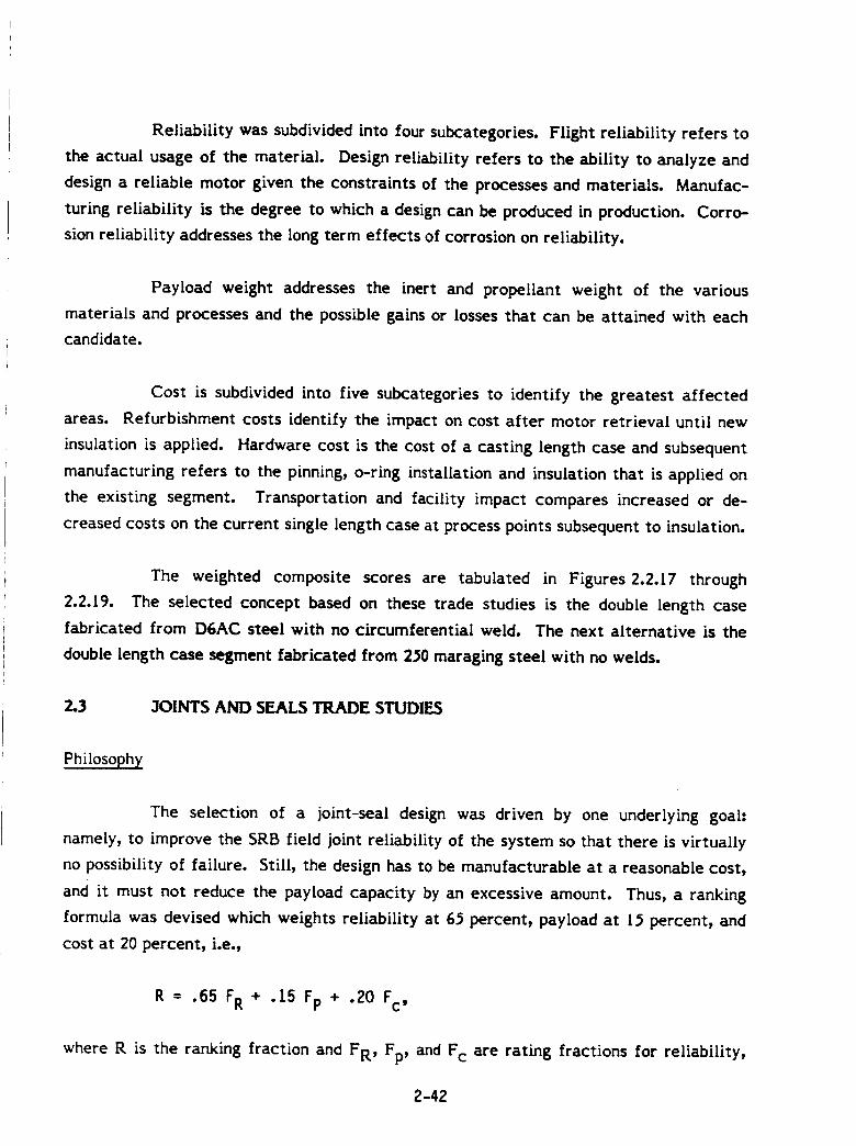
Reliability was subdivided into four subcategories. Flight reliability refers to
the actual usage of the material. Design reliability refers to the ability to analyze and
design a reliable motor given the constraints of the processes and materials. Manufac-
turing reliability is the degree to which a design can be produced in production. Corro-
sion reliability addresses the long term effects of corrosion on reliability.
Payload weight addresses the inert and propellant weight of the various
materials and processes and the possible gains or losses that can be attained with each
candidate.
Cost is subdivided into five subcategories to identify the greatest affected
areas. Refurbishment costs identify the impact on cost after motor retrieval until new
insulation is applied. Hardware cost is the cost of a casting length case and subsequent
manufacturing refers to the pinning_ o-ring installation and insulation that is applied on
the existing segment. Transportation and facility impact compares increased or de-
creased costs on the current single length case at process points subsequent to insulation.
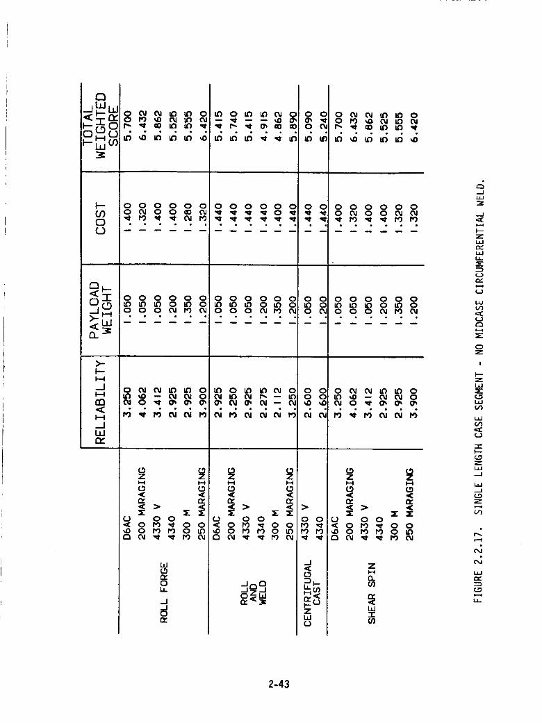
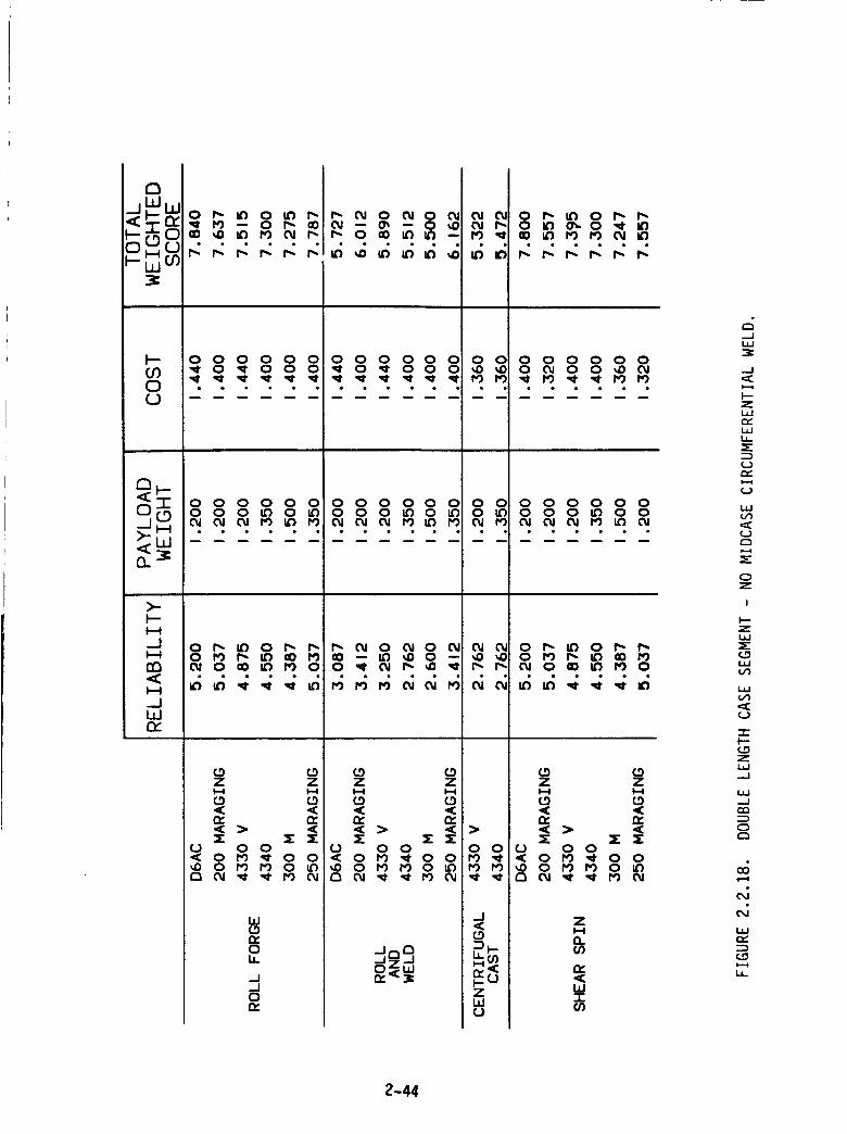
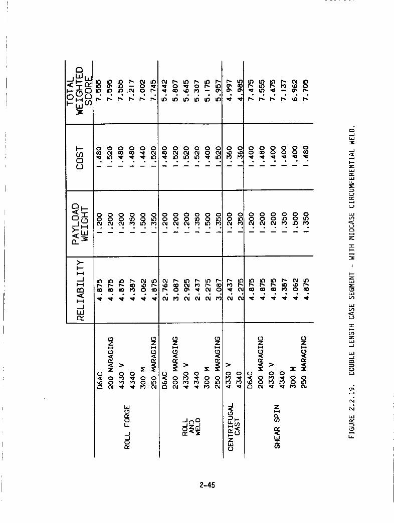
The weighted composite scores are tabulated in Figures 2.2.17 through
2.2.19. The selected concept based on these trade studies is the double length case
fabricated from D6AC steel with no circumferential weld. The next alternative is the
double length case segment fabricated from 2_0 maraging steel with no welds.
2.3 JOINTS AND SEALS TRADE STUDIES
Philosophy
The selection of a joint-seal design was driven by one underlying goal:
namely, to improve the SRB field joint reliability of the system so that there is virtually
no possibility of failure. Still, the design has to be manufacturable at a reasonable cost,
and it must not reduce the payload capacity by an excessive amount. Thus, a ranking
formula was devised which weights reliability at 6_ percent, payload at IS percent, and
cost at 20 percent, i.e.,
R = .65 FR + .15 Fp + .20 Fc,
where R is the ranking fraction and FR, Fp, and F c are rating fractions for reliability,
2-42
h.-C9OH °
0C)
O_
)-
d
O3
bJr_
0 _ _ _ _ 00 _ _ _ _ _
0 0 0 0 0 000JO0 _00J
088800.£oR_._
00_ i'_ I0 _0 0_ _0 -- O_ O_ 0O_ O ,_ O_ O_ O_
0 0 0 0 0 0 0 0 0 0 0 0 0 0
OOOoOOOOOoOOOOO 8
eo_e_oooo__eo_e_-eoo_-_o__-__o__
L9Z ZI,-I I-=4
£0 CO
CJ 0 0'_ 0 1"9 ,¢ 0 0_0 0 _0 PO 0 _
W
r_0b.
0n_
LtJ
--J
zt_J
Lt.
m_
W
_J
0Z
I
ZL_J
t_J
,m:_J
mmN--
ZILl.-J
L_--J
Z
C_
W
2-43
0 0 0 0 0 0Or) _ 0 _ 0 0 0
• • • • • •
oOOoOOOOO
n
0 0 0 0 0 0 0 0 0 0 0 0 00 0 _0 0 tO 0 _') 0 0 0 _) 0 0
>-
HI
rn<
_JWn-
W(.3n,0h
..JL_J
-J
ZL_C_i,iU-
t.)n_
¢_)
i,iO0
t.)C_
OZ
I
Zi,i
¢DUJ
i,i
(_)
I---(.ozL./.J..J
L._--J
:2DC_
L.IJ
1.4-
2-44
00C)
a.
>-F--
_.JH
rn<H
_JILlr_.
UL'i _ 6") _- 0_ IO
I_ tO _ r,9 ,,o O_ IO -- O_ I_
r,: r.: r: I-: _ r-
O O O O O OO _00 O O _
O O O O O OO O O tO O _O0d 0_ ¢Y _'0 _ t0
r-- _-- t-- _o ,,o r',-_o co 00 ro o _o
0 (.9Z Z
n, n,
0 0 0
Z
n
12:<WICO
--2
L_
_.J
F--z
c_t_
tDcc
__)
t_
c_
-c
!
z
_DL_
t_
-r"
ZL_J-.J
.--JCO
C_r",
I-.-I
ILlr.,-
2-45
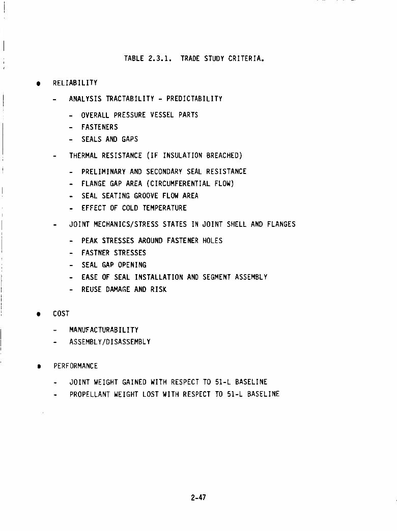
payload change, and cost, respectively, and are all based on a value between 1 and l0
where 10=best. The rating and ranking calculations are illustrated further into the
report. The rating criteria are defined in Table 2.3.1.
3oint Selection and Trade Features
Five joint-seal designs were chosen for this trade study. These candidates are
listed in Table 2.3.2 along with seal options. Seal characteristics are listed in Table
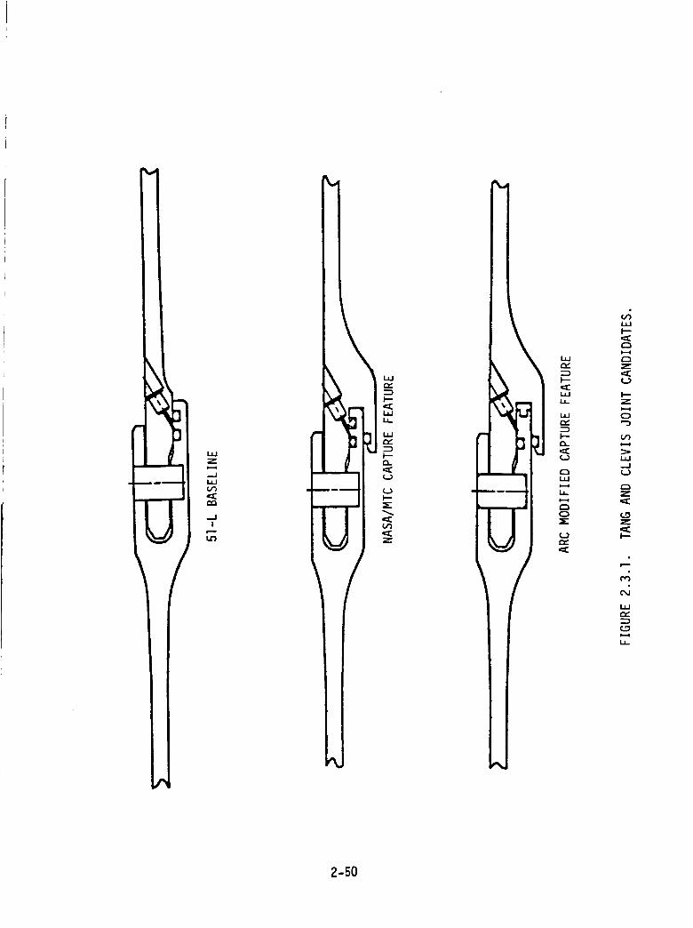
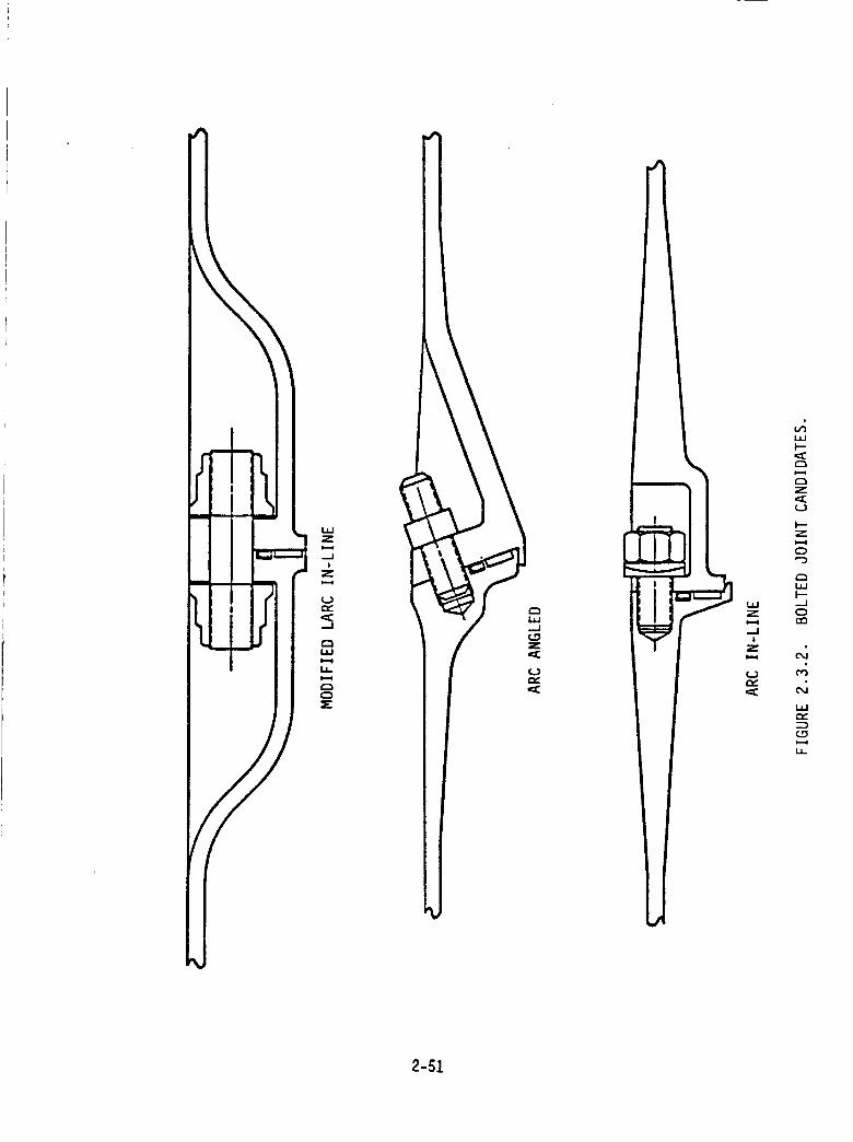
2.3.3. Sketches are shown in Figures 2.3.1 and 2.3.2. To accomplish these selections, we
first must consider the undesirable features of the 51-L original tang and clevis design.
The most important of these are:
I. The gap between the o-ring sealing surfaces tended to open during motorpressurization.
. The primary o-ring may not function (fill the gap) quickly enough if it isexposed to a low temperature environment, and it might be out of posi-tion due to back pressure from a leak check.
. If the insulation is breached and there is a flow path to the o-ring andcircumferentially around the o-ring, the thermal resistance of an elasto-meric o-ring is poor, since rubber and plastic o-ring materials deterioratein the neighborhood of 350*F.
We note here that the insulation design is an extremely important part ofthe overall field joint system and is discussed under Section 3.4. Thistrade study is limited to the metallic case joints and seals.
The joint is difficult to evaluate by structural analysis, since tolerancesinvolving the pin-pin hole fit, the tang and clevis fit, shim fit, and out ofroundness, as well as the affects of pin-pin hole friction, call for amyriad of assumptions. The Langley Research Center did an admirablejob analyzing the original design (Reference I, Section 3.1)but the above
objections were apparent. Additionally, this analysis indicated probableyielding of the pins and tang and clevis pin holes, which further compli-cates the evaluation of the _[-L joint design.
The concept of a bolted, flat seating joint using face seals was ARC's primary
consideration to overcome the above mentioned undesirable features:
2-46
O
TABLE 2.3.1. TRADE STUDY CRITERIA.
RELIABILITY
- ANALYSIS TRACTABILITY - PREDICTABILITY
- OVERALL PRESSURE VESSEL PARTS
- FASTENERS
- SEALS AND GAPS
- THERMAL RESISTANCE (IF INSULATION BREACHED)
- PRELIMINARY AND SECONDARY SEAL RESISTANCE
- FLANGE GAP AREA (CIRCUMFERENTIAL FLOW)
- SEAL SEATING GROOVE FLOW AREA
- EFFECT OF COLD TEMPERATURE
- JOINT MECHANICS/STRESS STATES IN JOINT SHELL AND FLANGES
- PEAK STRESSES AROUND FASTENER HOLES
- FASTNER STRESSES
- SEAL GAP OPENING
- EASE OF SEAL INSTALLATION AND SEGMENT ASSEMBLY
- REUSE DAMAGE AND RISK
COST
- MANUFACTURABILITY
- ASSEMBLY/DISASSEMBLY
PERFORMANCE
- JOINT WEIGHT GAINED WITH RESPECT TO 51-L BASELINE
- PROPELLANT WEIGHT LOST WITH RESPECT TO 51-L BASELINE
2-47
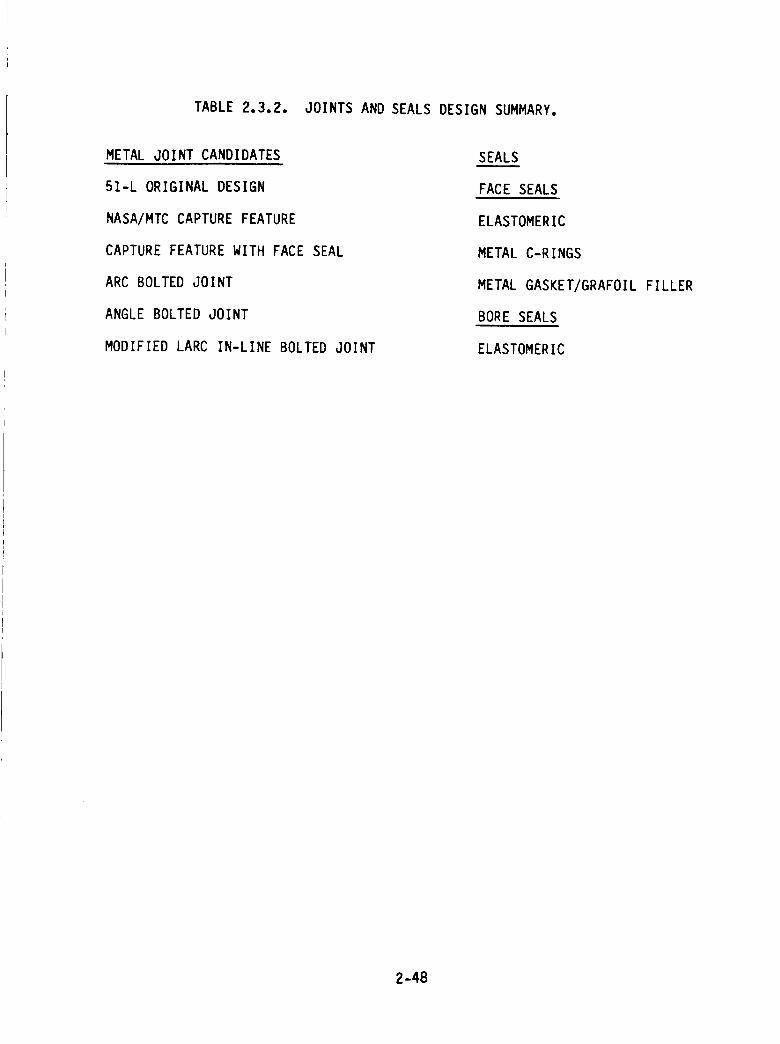
TABLE2.3.2. JOINTSANDSEALSDESIGNSUMMARY.
METAL JOINT CANDIDATES
51-L ORIGINAL DESIGN
NASA/MTC CAPTURE FEATURE
CAPTURE FEATURE WITH FACE SEAL
ARC BOLTED JOINT
ANGLE BOLTED JOINT
MODIFIED LARC IN-LINE BOLTED JOINT
SEALS
FACE SEALS
ELASTOMERIC
METAL C-RINGS
METAL GASKET/GRAFOIL FILLER
BORE SEALS
ELASTOMERIC
2-48
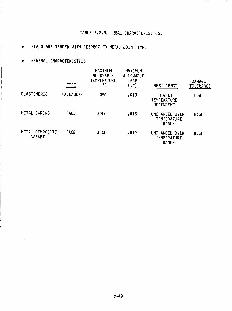
TABLE 2.3.3. SEAL CHARACTERISTICS.
• SEALS ARE TRADED WITH RESPECT TO METAL JOINT TYPE
• GENERAL CHARACTERISTICS
ELASTOMERIC
TYPE
MAXIMUM MAXIMUM
ALLOWABLE ALLOWABLETEMPERATURE GAP
OF (IN)
FACE/BORE 350 .013
METAL C-RING FACE 3000 .013
METAL COMPOSITE FACEGASKET
3000 .012
RESILIENCY
HIGHLY
TEMPERATURE
DEPENDENT
UNCHANGED OVER
TEMPERATURE
RANGE
UNCHANGED OVER
TEMPERATURE
RANGE
DAMAGE
TOLERANCE
LOW
HIGH
HIGH
2-49
\
_u
!
LU,
ILl
I.I-
L.I.J
"mI*--
Lul
I,
Q
I--
C_
Z
Z
0
(f)
I._.==Jr,.=)
Z
W
LI-
2-50
I iS I I_%
I
I l I I
I I I' "
i i
1=,p
, I
,Sf/
i
II
m
z
r,,,,-
.,,.,J
0-,,,e
I,.il.M
0
/
\
,,,.,,J
z
I,-,-
r-i
z
0
ILl
..J0
oo
d
_D
M
I.I--
2-$I
, The flat seating surfaces make possible the use of metallic seals. Ajacketed [nconel material with a graphite foil filler makes a perfectstatic seal that is not effected by leak check back pressure and isresistant to temperatures of over 3000=F. Metallic (Inconel) c-ringswere choosen for the back-up or secondary seals, and will have the samehigh temperature resistance, while taking up less flange width.
e The flat seating surfaces and horizontal seal grooves provide easy instal-lation of the seals, and more importantly, easy inspection. Mating theupper segment will not scratch the seals or surfaces and will not lead tometal shavings or other debris.
e The metallic gaskets are not pressure activated and are not sensitive to
low environmental temperatures. Furthermore, both the metal gasketand the c-ring design have been used extensively in the steam generationindustry (nuclear and conventional) to contain high pressure and hightemperature steam vapor.
_e Finally, the bolted joint design is analytically tractable, and as such, theflange opening and state-of-stress can be kept to acceptable limits byengineering analysis that is not subject to assumptions or other guess-work. The first-cut design analysis is presented in Section 3.1.
In October of 1986, ARC was fortunate to receive a presentation by LARC of
their in-line bolted joint. The joint design is very similar to the ARC design and was an
obvious choice for one of the prime candidates in the trade study. One advantageous
feature is the lack of threaded stud holes, which, in the case of the ARC design, would
require inspection for reuse. We note that, for reasons mentioned above, the LARC in-
line joint has been rated using the metal gasket and c-ring seal combination of the ARC
design. This is presently thought to be a more reliable combination than the original
LARC Viton o-ring and metal c-ring combination.
We note that both the ARC axially bolted joint and the LARC in-line bolted
joint are receiving design structural analysis iterations and are not, at present, optimal.
The LARC design received a slightly higher ranking, presented subsequently.
ARC has also included an angle bolted joint for consideration. This joint is
intended to retain the main features of the axially bolted design, but it allows the addi-
tional feature of hydraulically pre-tensioned studs. Since pretensioning is essential to
the bolted design (to minimize flange opening), it was decided to include this configura-
tion as a backup. This is for the eventuality that stud elongation methods should fall
short as a stud or bolt preloading scheme.
2-52
The NASA/MTC capture feature was also included in the trade study, since it
has (a) been chosen for the 1988 SRB, (b) been extensively scrutinized, and (c) received a
good structural analysis study by LARC (Reference l, Section 3.[). The design is thought
to serve as a good baseline for these studies, i.e., it should rank lower than the so-called
clean paper designs.
The final subject of this trade study is the capture-feature concept with an
elastomeric face seal between the capture feature lip and the inner clevis arm. This
addition is thought to add reliability to the o-ring arrangement, since it would have the
characteristics of a static seal although not the temperature resistance.
Trade Study Results
The ARC axially bolted joint was structurally analyzed in detail via the
NASTRAN finite element method, and the results are presented in Section 3.1 of the
Design Studies. Since this analysis covered only the Nfirst cut w configuration, and since
the results show a certain amount of overstressing and excess gap opening, the model
weight was increased by 20 percent, and the propellant loss by 10 percent for the trade
studies.
The NASA/Langley structural analyses (References l and 2, Section 3.1) were
used heavily for the evaluation of the ncapture feature w tang and clevis joint and the
LARC Win-line bolted joint, w The ARC nangle bolt joint R was evaluated by estimate only,
since no detailed structural analysis was performed.
The trade study rating criteria, ratings, and explanatory comments are given
for all of the joints in Tables 2.3.4 through 2.3.8. We note that reliability ratings are
defined on a scale of l to 10. The final reliability factor is defined as the average of the
individual ratings, and is in no way related to the probability of failure from classical
reliability engineering. The same averaging is performed for the manufacturability and
cost criteria. The payload weight factor is normalized to a 60,000 pound payload, and as
such it represents the percent of payload lost or gained due to the presence of redesigned
joints. The weight factors are summarized in Table 2.3.9. The absolute inert and propel-
lant weight changes are shown in Table 2.3. l 0.
2-53
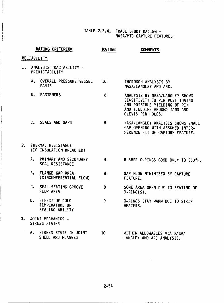
TABLE 2.3.4. TRADE STUDY RATING -
NASA/MTC CAPTURE FEATURE,
IU_TING CRITERION
RELIABILITY
1. ANALYSIS TRACTABILITY -
PREDICTABILITY
A. OVERALL PRESSURE VESSELPARTS
B. FASTENERS
C. SEALS AND GAPS
RATING COI_ENTS
10
8
THOROUGH ANALYSIS BY
NASA/LANGLEY AND ARC.
ANALYSIS BY NASA/LANGLEY SHOWS
SENSITIVITY TO PIN POSITIONING
AND POSSIBLE YIELDING OF PINAND YIELDING AROUND TANG AND
CLEVIS PIN HOLES.
NASA/LANGLEY ANALYSIS SHOWS SMALL
GAP OPENING WITH ASSUMED INTER-
FERENCE FIT OF CAPTURE FEATURE.
.
.
THERMAL RESISTANCE
(IF INSULATION BREACHED)
A. PRIMARY AND SECONDARY
SEAL RESISTANCE
B. FLANGE GAP AREA
(CIRCUMFERENTIAL FLOW)
C. SEAL SEATING GROOVEFLOW AREA
Do EFFECT OF COLD
TEMPERATURE ON
SEALING ABILITY
JOINT MECHANICS -
STRESS STATES
A. STRESS STATE IN JOINT
SHELL AND FLANGES
4
8
RUBBER O-RINGS GOOD ONLY TO 350°F.
8
9
10
GAP FLOW MINIMIZED BY CAPTURE
FEATURE.
SOME AREA OPEN DUE TO SEATING OF
O-RING(S).
O-RINGS STAY WARM DUE TO STRIP
HEATERS.
WITHIN ALLOWABLES VIA NASA/
LANGLEY AND ARC ANALYSIS.
2-54
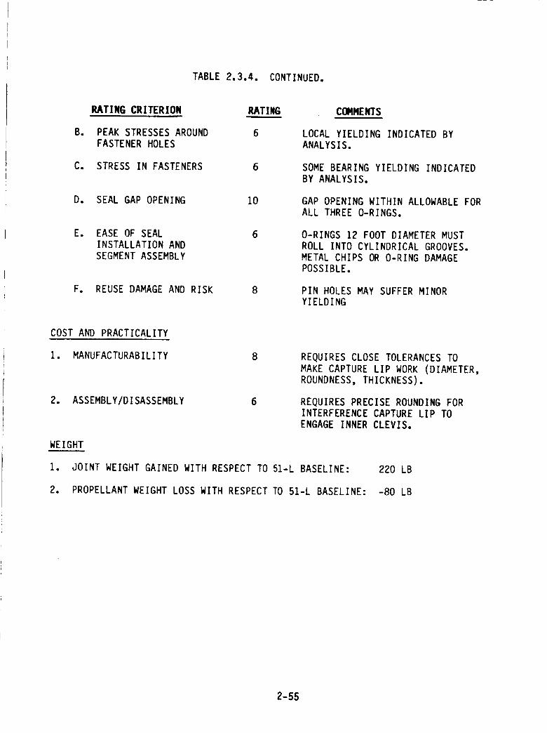
TABLE2.3.4. CONTINUED.
B.
RkTING CRITERION
PEAK STRESSES AROUND
FASTENER HOLES
C. STRESS IN FASTENERS
D. SEAL GAP OPENING
RATING
6
6
10
E. EASE OF SEAL 6
INSTALLATION AND
SEGMENT ASSEMBLY
F. REUSE DAMAGE AND RISK 8
COMMENTS
LOCAL YIELDING INDICATED BYANALYSIS.
SOME BEARING YIELDING INDICATED
BY ANALYSIS.
GAP OPENING WITHIN ALLOWABLE FOR
ALL THREE O-RINGS.
O-RINGS 12 FOOT DIAMETER MUST
ROLL INTO CYLINDRICAL GROOVES.
METAL CHIPS OR O-RING DAMAGE
POSSIBLE.
PIN HOLES MAY SUFFER MINORYIELDING
COST AND PRACTICALITY
1. MANUFACTURABILITY
2. ASSEMBLY/DISASSEMBLY 6
WEIGHT
REQUIRES CLOSE TOLERANCES TO
MAKE CAPTURE LIP WORK (DIAMETER,ROUNDNESS, THICKNESS).
REQUIRES PRECISE ROUNDING FORINTERFERENCE CAPTURE LIP TO
ENGAGE INNER CLEVIS,
1. JOINT WEIGHT GAINED WITH RESPECT TO 51-L BASELINE: 220 LB
2. PROPELLANT WEIGHT LOSS WITH RESPECT TO 51-L BASELINE: -80 LB
2-55
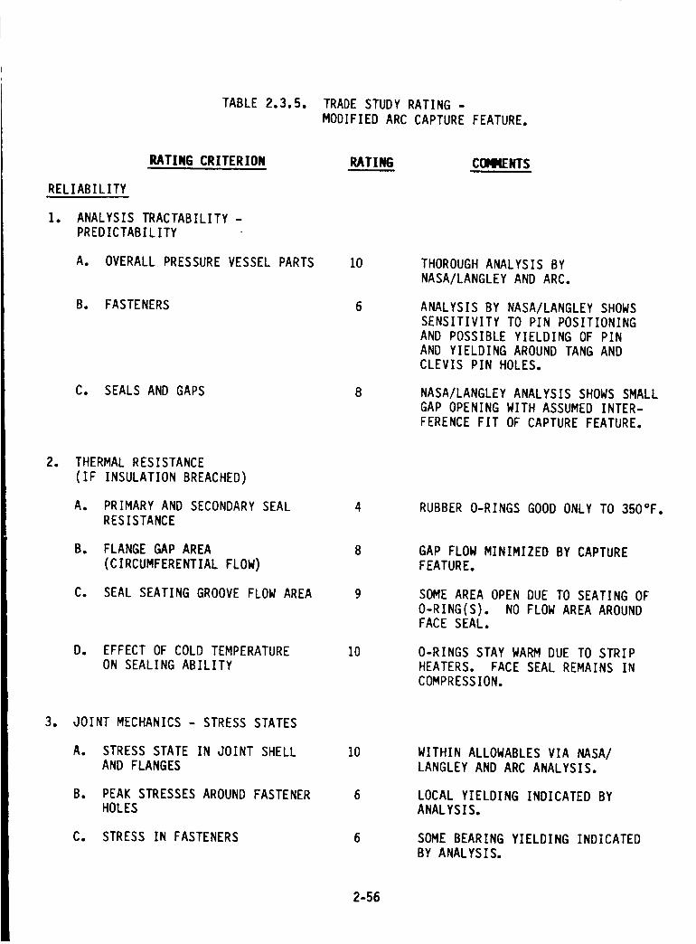
TABLE 2.3.5. TRADE STUDY RATING -
MODIFIED ARC CAPTURE FEATURE,
RATING CRITERION
RELIABILITY
1. ANALYSIS TRACTABILITY -PREDICTABILITY
A. OVERALL PRESSURE VESSEL PARTS
B. FASTENERS
C. SEALS AND GAPS
RATING CONNENTS
10 THOROUGH ANALYSIS BY
NASA/LANGLEY AND ARC.
ANALYSIS BY NASA/LANGLEY SHOWS
SENSITIVITY TO PIN POSITIONING
AND POSSIBLE YIELDING OF PIN
AND YIELDING AROUND TANG AND
CLEVIS PIN HOLES.
NASA/LANGLEY ANALYSIS SHOWS SMALL
GAP OPENING WITH ASSUMED INTER-
FERENCE FIT OF CAPTURE FEATURE.
. THERMAL RESISTANCE
(IF INSULATION BREACHED)
A. PRIMARY AND SECONDARY SEAL
RESISTANCE
B, FLANGE GAP AREA
(CIRCUMFERENTIAL FLOW)
C. SEAL SEATING GROOVE FLOW AREA
D. EFFECT OF COLD TEMPERATUREON SEALING ABILITY
10
RUBBER O-RINGS GOOD ONLY TO 350°F.
GAP FLOW MINIMIZED BY CAPTURE
FEATURE.
SOME AREA OPEN DUE TO SEATING OF
O-RING(S). NO FLOW AREA AROUNDFACE SEAL.
O-RINGS STAY WARM DUE TO STRIP
HEATERS. FACE SEAL REMAINS IN
COMPRESSION.
. JOINT MECHANICS - STRESS STATES
A. STRESS STATE IN JOINT SHELL
AND FLANGES
B. PEAK STRESSES AROUND FASTENERHOLES
C. STRESS IN FASTENERS
10
6
6
WITHIN ALLOWABLES VIA NASA/
LANGLEY AND ARC ANALYSIS.
LOCAL YIELDING INDICATED BY
ANALYSIS.
SOME BEARING YIELDING INDICATED
BY ANALYSIS.
2-56
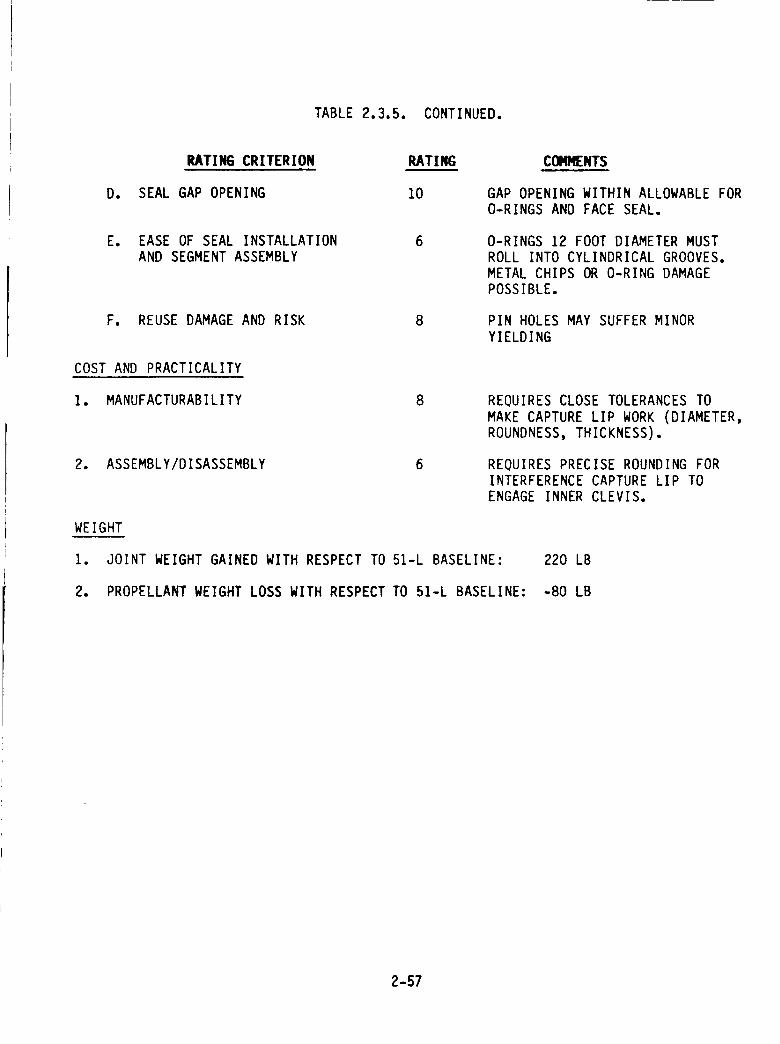
TABLE 2.3.5. CONTINUED.
RATING CRITERION RATING COMMENTS
D. SEAL GAP OPENING 10 GAP OPENING WITHIN ALLOWABLE FOR
O-RINGS AND FACE SEAL.
E. EASE OF SEAL INSTALLATION 6
AND SEGMENT ASSEMBLY
O-RINGS 12 FOOT DIAMETER MUST
ROLL INTO CYLINDRICAL GROOVES.
METAL CHIPS OR O-RING DAMAGE
POSSIBLE.
F. REUSE DAMAGE AND RISK PIN HOLES MAY SUFFER MINOR
YIELDING
COST AND PRACTICALITY
1. MANUFACTURABILITY 8 REQUIRES CLOSE TOLERANCES TO
MAKE CAPTURE LIP WORK (DIAMETER,ROUNDNESS, THICKNESS).
2. ASSEMBLY/DISASSEMBLY 6 REQUIRES PRECISE ROUNDING FOR
INTERFERENCE CAPTURE LIP TOENGAGE INNER CLEVIS.
WEIGHT
1. JOINT WEIGHT GAINED WITH RESPECT TO 51-L BASELINE: 220 LB
2. PROPELLANT WEIGHT LOSS WITH RESPECT TO 51-L BASELINE: -80 LB
2-57
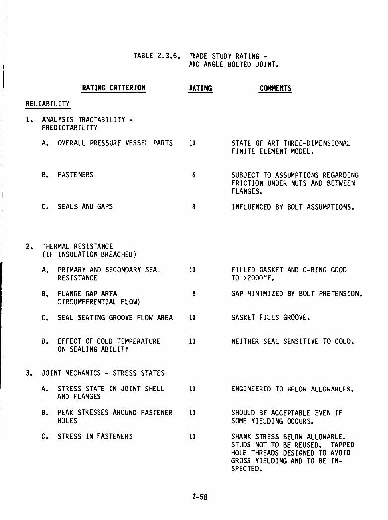
TABLE 2.3.6. TRADE STUDY RATING -
ARC ANGLE BOLTED JOINT.
PJ_TING CRITERION
RELIABILITY
1. ANALYSIS TRACTABILITY -
PREDICTABILITY
A. OVERALL PRESSURE VESSEL PARTS
RATING CONMENTSw
10 STATE OF ART THREE-DIMENSIONAL
FINITE ELEMENT MODEL.
B. FASTENERS
C. SEALS AND GAPS
SUBJECT TO ASSUMPTIONS REGARDING
FRICTION UNDER NUTS AND BETWEEN
FLANGES.
INFLUENCED BY BOLT ASSUMPTIONS.
. THERMAL RESISTANCE
(IF INSULATION BREACHED)
A. PRIMARY AND SECONDARY SEAL
RESISTANCE
B. FLANGE GAP AREA
CIRCUMFERENTIAL FLOW)
C. SEAL SEATING GROOVE FLOW AREA
10
8
FILLED GASKET AND C-RING GOOD
TO >2000°F.
GAP MINIMIZED BY BOLT PRETENSION.
10 GASKET FILLS GROOVE.
D. EFFECT OF COLD TEMPERATURE
ON SEALING ABILITY
10 NEITHER SEAL SENSITIVE TO COLD.
. JOINT MECHANICS - STRESS STATES
A. STRESS STATE IN JOINT SHELL
AND FLANGES
B. PEAK STRESSES AROUND FASTENER
HOLES
C. STRESS IN FASTENERS
10 ENGINEERED TO BELOW ALLOWABLES.
10
10
SHOULD BE ACCEPTABLE EVEN IF
SOME YIELDING OCCURS.
SHANK STRESS BELOW ALLOWABLE.
STUDS NOT TO BE REUSED. TAPPED
HOLE THREADS DESIGNED TO AVOID
GROSS YIELDING AND TO BE IN-
SPECTED.
2-58
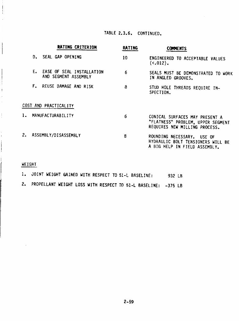
TABLE 2.3.6. CONTINUED.
RATING CRITERION
D. SEAL GAP OPENING
Ee EASE OF SEAL INSTALLATION
AND SEGMENT ASSEMBLY
F. REUSE DAMAGE AND RISK
RATING
10
8
COMMENTS
ENGINEEREDTO ACCEPTABLEVALUES(<.OZ2).
SEALS MUST BE DEMONSTRATED TO WORK
IN ANGLED GROOVES.
STUD HOLE THREADS REQUIRE IN-SPECTION.
COST AND PRACTICALITY
1. MANUFACTURABILITY
2. ASSEMBLY/DISASSEMBLY
6 CONICAL SURFACES MAY PRESENT A
"FLATNESS" PROBLEM, UPPER SEGMENT
REQUIRES NEW MILLING PROCESS.
ROUNDING NECESSARY. USE OF
HYDRAULIC BOLT TENSIONERS WILL BE
A BIG HELP IN FIELD ASSEMBLY.
WEIGHT
1. JOINT WEIGHT GAINED WITH RESPECT TO 51-L BASELINE:
2. PROPELLANT WEIGHT LOSS WITH RESPECT TO 51-L BASELINE:
932 LB
-375 LB
2-59
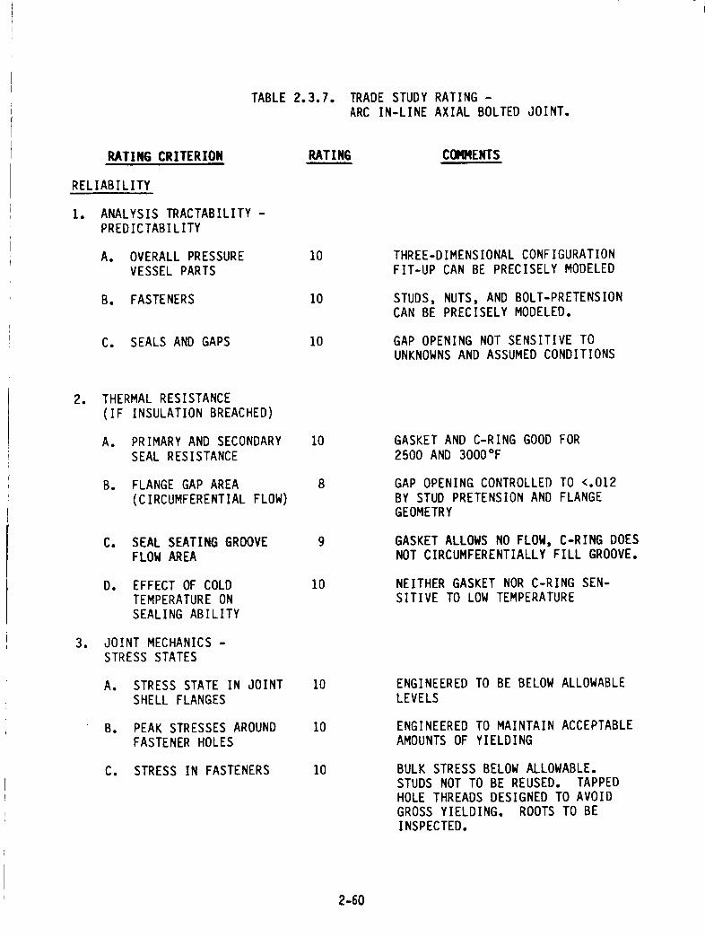
TABLE 2.3.7. TRADE STUDY RATING -
ARC IN-LINE AXIAL BOLTED JOINT.
PJ_TING CRITERION
RELIABILITY
1. ANALYSIS TRACTABILITY -
PREDICTABILITY
A. OVERALL PRESSURE
VESSEL PARTS
B. FASTENERS
C. SEALS AND GAPS
RATING COMMENTS
10
10
10
THREE-DIMENSIONAL CONFIGURATION
FIT-UP CAN BE PRECISELY MODELED
STUDS, NUTS, AND BOLT-PRETENSION
CAN BE PRECISELY MODELED.
GAP OPENING NOT SENSITIVE TO
UNKNOWNS AND ASSUMED CONDITIONS
.
.
THERMAL RESISTANCE
(IF INSULATION BREACHED)
A. PRIMARY AND SECONDARY
SEAL RESISTANCE
B. FLANGE GAP AREA
(CIRCUMFERENTIAL FLOW)
C. SEAL SEATING GROOVE
FLOW AREA
Do EFFECT OF COLD
TEMPERATURE ON
SEALING ABILITY
JOINT MECHANICS -
STRESS STATES
A. STRESS STATE IN JOINT
SHELL FLANGES
B. PEAK STRESSES AROUND
FASTENER HOLES
C. STRESS IN FASTENERS
10
10
10
10
10
GASKET AND C-RING GOOD FOR
2500 AND 3000°F
GAP OPENING CONTROLLED TO <.012
BY STUD PRETENSION AND FLANGE
GEOMETRY
GASKET ALLOWS NO FLOW, C-RING DOES
NOT CIRCUMFERENTIALLY FILL GROOVE.
NEITHER GASKET NOR C-RING SEN-
SITIVE TO LOW TEMPERATURE
ENGINEERED TO BE BELOW ALLOWABLE
LEVELS
ENGINEERED TO MAINTAIN ACCEPTABLE
AMOUNTS OF YIELDING
BULK STRESS BELOW ALLOWABLE.
STUDS NOT TO BE REUSED. TAPPED
HOLE THREADS DESIGNED TO AVOID
GROSS YIELDING. ROOTS TO BE
INSPECTED.
2-60
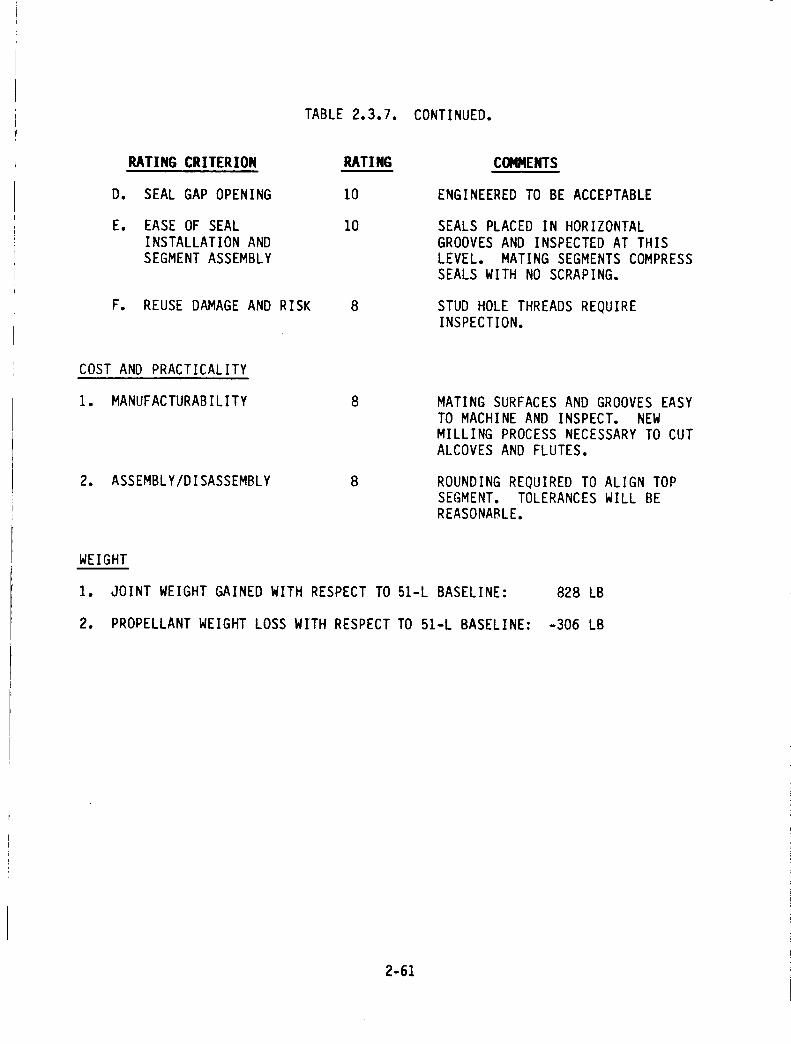
TABLE 2.3.7. CONTINUED.
IL_TING CRITERION
D. SEAL GAP OPENING
E. EASE OF SEAL
INSTALLATION AND
SEGMENT ASSEMBLY
F. REUSE DAMAGE AND RISK
RATING
10
I0
8
CONNENTS
ENGINEERED TO BE ACCEPTABLE
SEALS PLACED IN HORIZONTAL
GROOVES AND INSPECTED AT THIS
LEVEL. MATING SEGMENTS COMPRESS
SEALS WITH NO SCRAPING.
STUD HOLE THREADS REQUIRE
INSPECTION.
COST AND PRACTICALITY
1. MANUFACTURABILITY 8
2. ASSEMBLY/DISASSEMBLY 8
MATING SURFACES AND GROOVES EASY
TO MACHINE AND INSPECT. NEW
MILLING PROCESS NECESSARY TO CUT
ALCOVES AND FLUTES.
ROUNDING REQUIRED TO ALIGN TOP
SEGMENT, TOLERANCES WILL BE
REASONABLE.
WEIGHT
1. JOINT WEIGHT GAINED WITH RESPECT TO 51-L BASELINE:
2. PROPELLANT WEIGHT LOSS WITH RESPECT TO 51-L BASELINE:
828 LB
-306 LB
2-61
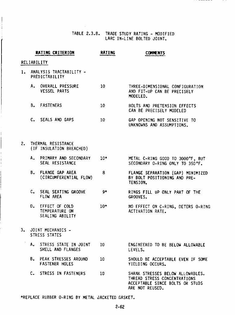
TABLE 2.3.8. TRADE STUDY RATING - MODIFIED
LARC IN-LINE BOLTED JOINT.
RATING CRITERION
RELIABILITY
1. ANALYSIS TRACTABILITY -
PREDICTABILITY
A. OVERALL PRESSURE
VESSEL PARTS
RATING COMI_NTS
10
B. FASTENERS 10
C. SEALS AND GAPS 10
THREE-DIMENSIONAL CONFIGURATION
AND FIT-UP CAN BE PRECISELY
MODELED.
BOLTS AND PRETENSION EFFECTS
CAN BE PRECISELY MODELED
GAP OPENING NOT SENSITIVE TO
UNKNOWNS AND ASSUMPTIONS.
. THERMAL RESISTANCE
(IF INSULATION BREACHED)
A. PRIMARY AND SECONDARY
SEAL RESISTANCE
B. FLANGE GAP AREA
(CIRCUMFERENTIAL FLOW)
C. SEAL SEATING GROOVE
FLOW AREA
10"
8
9*
D. EFFECT OF COLD 10"
TEMPERATURE ON
SEALING ABILITY
METAL C-RING GOOD TO 3000°F, BUT
SECONDARY O-RING ONLY TO 350°F.
FLANGE SEPARATION (GAP) MINIMIZEDBY BOLT POSITIONING AND PRE-
TENSION,
RINGS FILL UP ONLY PART OF THE
GROOVES.
NO EFFECT ON C-RING, DETERS O-RINGACTIVATION RATE.
3. JOINT MECHANICS -
STRESS STATES
A. STRESS STATE IN JOINT
SHELL AND FLANGES
10 ENGINEERED TO BE BELOW ALLOWABLE
LEVELS.
B. PEAK STRESSES AROUND
FASTENER HOLES
10 SHOULD BE ACCEPTABLE EVEN IF SOME
YIELDING OCCURS.
C. STRESS IN FASTENERS 10 SHANK STRESSES BELOW ALLOWABLES.
THREAD STRESS CONCENTRATIONS
ACCEPTABLE SINCE BOLTS OR STUDS
ARE NOT REUSED.
*REPLACE RUBBER O-RING BY METAL JACKETED GASKET.
2-62
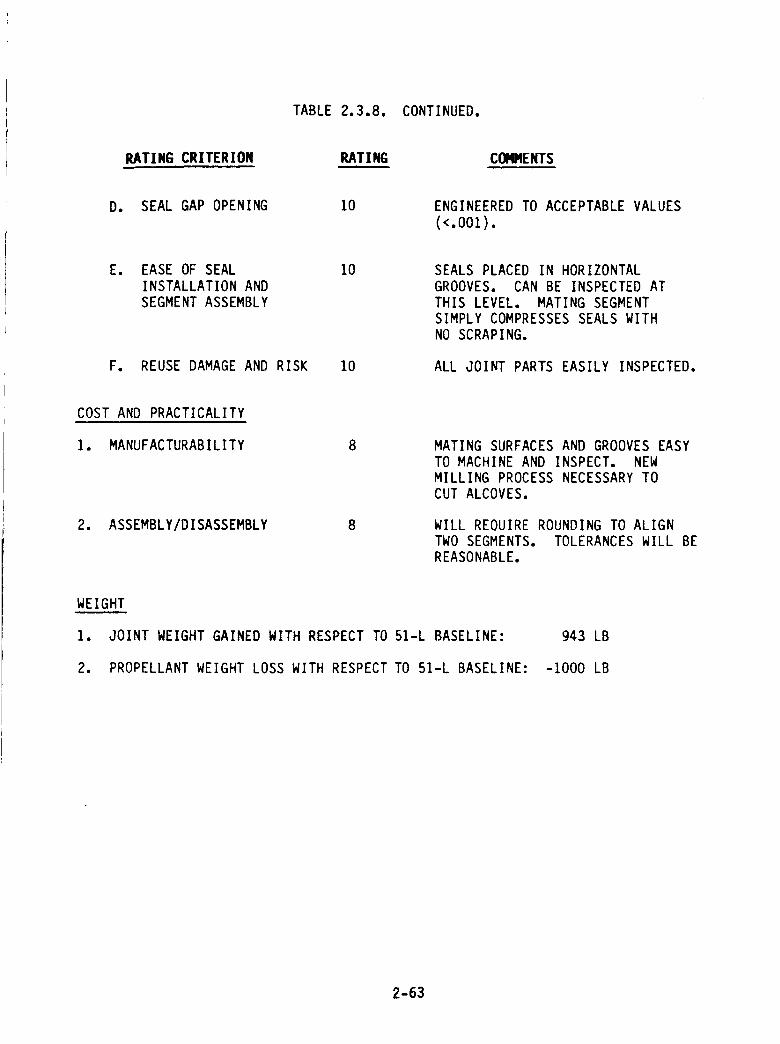
TABLE 2.3.8. CONTINUED.
RATING CRITERION RATING COI,gqENTS
D. SEAL GAP OPENING 10 ENGINEEREDTO ACCEPTABLEVALUES(<.OOZ).
E. EASE OF SEAL 10
INSTALLATION AND
SEGMENT ASSEMBLY
F. REUSE DAMAGE AND RISK 10
SEALS PLACED IN HORIZONTAL
GROOVES. CAN BE INSPECTED AT
THIS LEVEL. MATING SEGMENTSIMPLY COMPRESSES SEALS WITH
NO SCRAPING.
ALL JOINT PARTS EASILY INSPECTED.
COST AND PRACTICALITY
I. MANUFACTURABILITY 8
2. ASSEMBLY/DISASSEMBLY 8
MATING SURFACES AND GROOVES EASY
TO MACHINE AND INSPECT. NEW
MILLING PROCESS NECESSARY TO
CUT ALCOVES.
WILL REOUIRE ROUNDING TO ALIGN
TWO SEGMENTS. TOLERANCES WILL BE
REASONABLE.
WEIGHT
I. JOINT WEIGHT GAINED WITH RESPECT TO 51-L BASELINE:
2. PROPELLANT WEIGHT LOSS WITH RESPECT TO 51-L BASELINE:
943 LB
-1000 LB
2-63
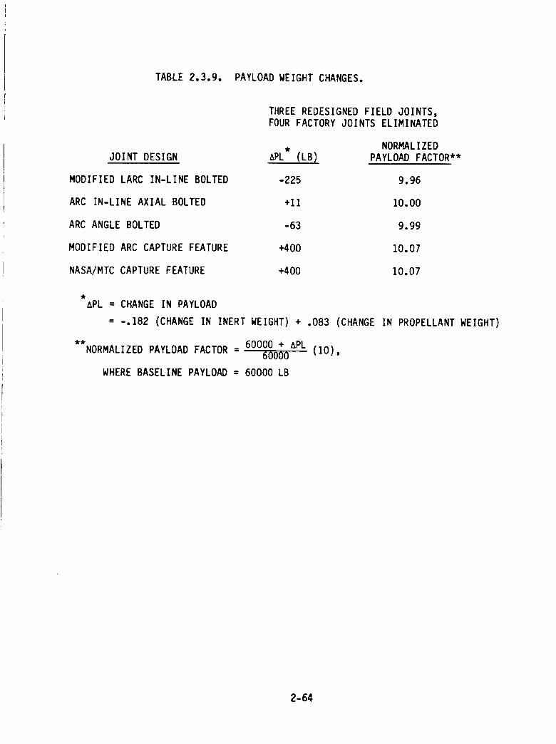
TABLE 2.3.9. PAYLOAD WEIGHT CHANGES.
JOINT DESIGN
MODIFIED LARC IN-LINE BOLTED
ARC IN-LINE AXIAL BOLTED
ARC ANGLE BOLTED
MODIFIED ARC CAPTURE FEATURE
NASA/MTC CAPTURE FEATURE
THREE REDESIGNED FIELD JOINTS,FOUR FACTORY JOINTS ELIMINATED
APL (LB)
-225
+11
-63
+400
+400
NORMALIZED
PAYLOAD FACTOR**
9.96
10.00
9.99
10.07
10.07
APL = CHANGE IN PAYLOAD
= -.182 (CHANGE IN INERT WEIGHT) + .083 (CHANGE IN PROPELLANT WEIGHT)
**NORMALIZED PAYLOAD FACTOR - 60000 + APL- 60000 (I0),
WHERE BASELINE PAYLOAD = 60000 LB
2-64
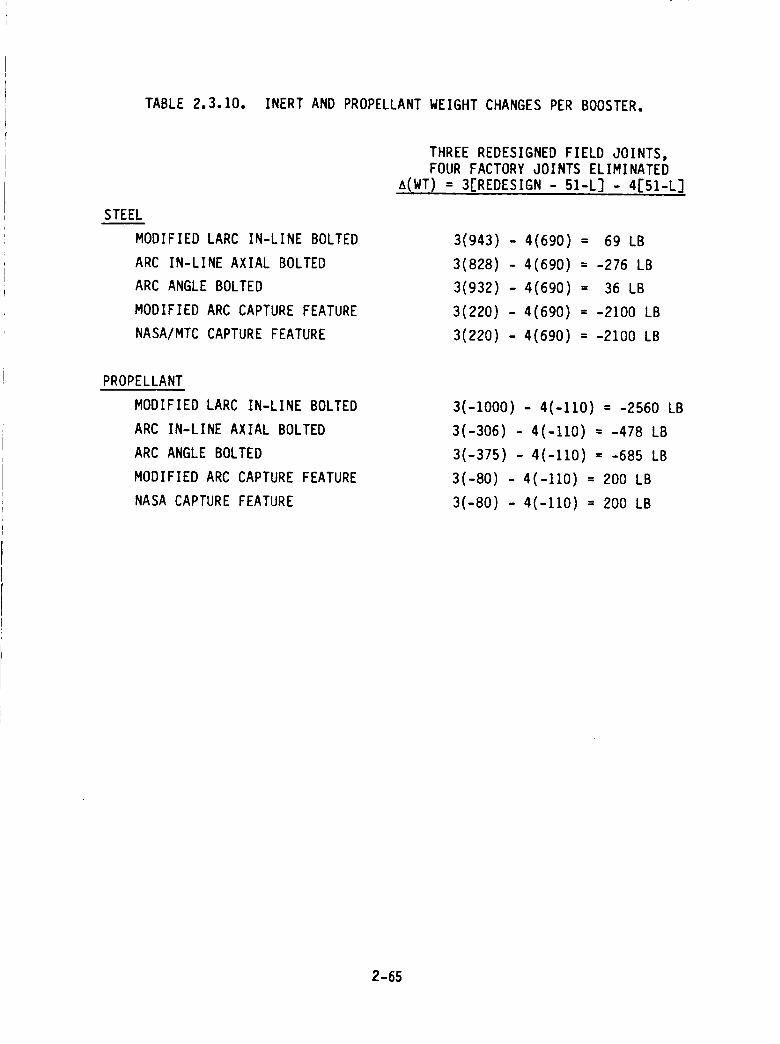
TABLE 2.3.10. INERT AND PROPELLANT WEIGHT CHANGES PER BOOSTER.
STEEL
MODIFIED LARC IN-LINE BOLTED
ARC IN-LINE AXIAL BOLTED
ARC ANGLE BOLTED
MODIFIED ARC CAPTURE FEATURE
NASA/MTC CAPTURE FEATURE
PROPELLANT
MODIFIED LARC IN-LINE BOLTED
ARC IN-LINE AXIAL BOLTED
ARC ANGLE BOLTED
MODIFIED ARC CAPTURE FEATURE
NASA CAPTURE FEATURE
THREE REDESIGNED FIELD JOINTS,FOUR FACTORY JOINTS ELIMINATED
A(WT) = 3[REDESIGN - 51-L] - 4151-L]
3(943) - 4(690) = 69 LB
3(828) - 4(690) = -276 LB
3(932) - 4(690) = 36 LB
3(220) - 4(690) = -2100 LB
3(220) - 4(690) = -2100 LB
3(-1000) - 4(-110) = -2560 LB
3(-306) - 4(-110) = -478 LB
3(-375) - 4(-110) = -685 LB
3(-80) - 4(-II0) = 200 LB
3(-80) - 4(-110) = 200 LB
2-65
The calculation of the final joint/seal ranking factor is illustrated by sample
in Table 2.3.11, and the summary of all rankings is given in Table 2.3.12.
We note that the LARC in-line bolted joint was modified for this evaluation
by replacing the primary o-ring seal with a metal jacketed graphite foil-filled type of
gasket. This should be a better seal for withstanding the back pressure of the leak check,
since the gasket will not shift position. Additionally, the temperature resistance of the
metal gasket is far superior to a rubber o-ring and should be capable of withstanding
exposure temperatures beyond 2500°F. Also, an aligning shear lip, similar to that on the
ARC bolted joint, is presently planned as a modification.
Conclusions and Recommendations
The net results of the trade studies are shown in Table 2.3.13. The recom-
mended joint redesign is the NASA/Langley in-line bolted configuration with the above
mentioned modifications, and, perhaps, some slight geometry changes still to be deter-
mined.
2.4 INSULATION TRADE STUDIES
The insulation trade study was begun with an identification of the asbestos-
containing materials in the SRM which must be replaced. Asbestos is found in the cur-
rent design in the case internal insulation, the igniter internal and external insulation,
the molded and cast inhibitors, the liner, the nozzle, and in certain components in the
Safe and Arm (S&A) device. Discussions of the liner, nozzle, igniter, and S&A material
replacements appear in those respective sections of this report. This section presents
the effort conducted on the case insulation. The insulation selected for the igniter and
molded inhibitor resulted from the trade study conducted for the case insulation.
The initial effort for the case insulation trade study was to evaluate potential
fabrication processes. This evaluation will be presented in Section 2.4.1. Once a fabri-
cation process was selected, an insulation trade study based on the selected process was
conducted. This case insulation trade study is presented in Section 2.4.2.
2-66
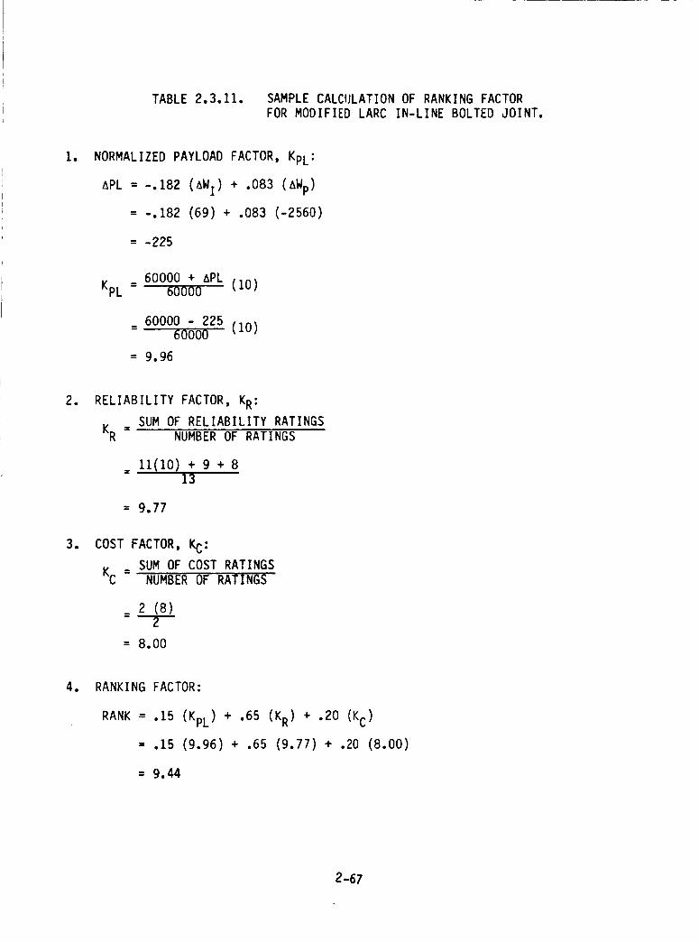
TABLE 2.3.11. SAMPLE CALCULATION OF RANKING FACTOR
FOR MODIFIED LARC IN-LINE BOLTED JOINT.
I. NORMALIZED PAYLOAD FACTOR, KpL:
APL = -.182 (AWI) + .083 (AWp)
= -.182 (69) + .083 (-2560)
= -225
_ 60000 + APLKpL 60000 (10)
60000 - 225- 60000 (I0)
= 9.96
. RELIABILITY FACTOR, KR:
SUM OF RELIABILITY RATINGSKR = NUMBER OF RATINGS
11(10) + 9 + 813
= 9.77
. COST FACTOR, KC:
KC _ SUM OF COST RATINGSNUMBER OF RATINGS
_ 2 (8)
= 8.00
. RANKING FACTOR:
RANK = .15 (KpL) + .65 (KR) + .20 (KC)
= .15 (9.96) + .65 (9.77) + .20 (8.00)
= 9.44
2-67
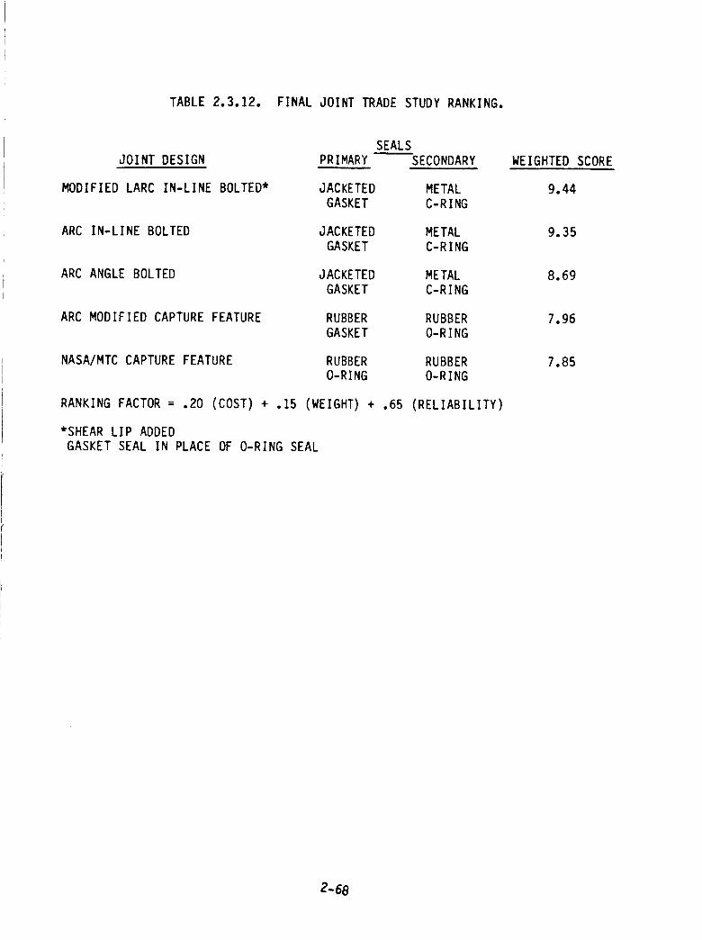
TABLE 2.3.12. FINAL JOINT TRADE STUDY RANKING.
SEALS
JOINT DESIGN PRIMARY SECONDARY
MODIFIED LARC IN-LINE BOLTED* JACKETED METAL
GASKET C-R ING
ARC IN-LINE BOLTED JACKETED METAL
GASKET C-RING
ARC ANGLE BOLTED JACKETED METAL
GASKET C-RING
ARC MODIFIED CAPTURE FEATURE RUBBER RUBBER
GASKET O-RING
NASA/MTC CAPTURE FEATURE RUBBER RUBBER
O-RING O-RING
RANKING FACTOR = .20 (COST) + .15 (WEIGHT) + .65 (RELIABILITY)
*SHEAR LIP ADDED
GASKET SEAL IN PLACE OF O-RING SEAL
WEIGHTED SCORE
9.44
9.35
8.69
7.96
7.85
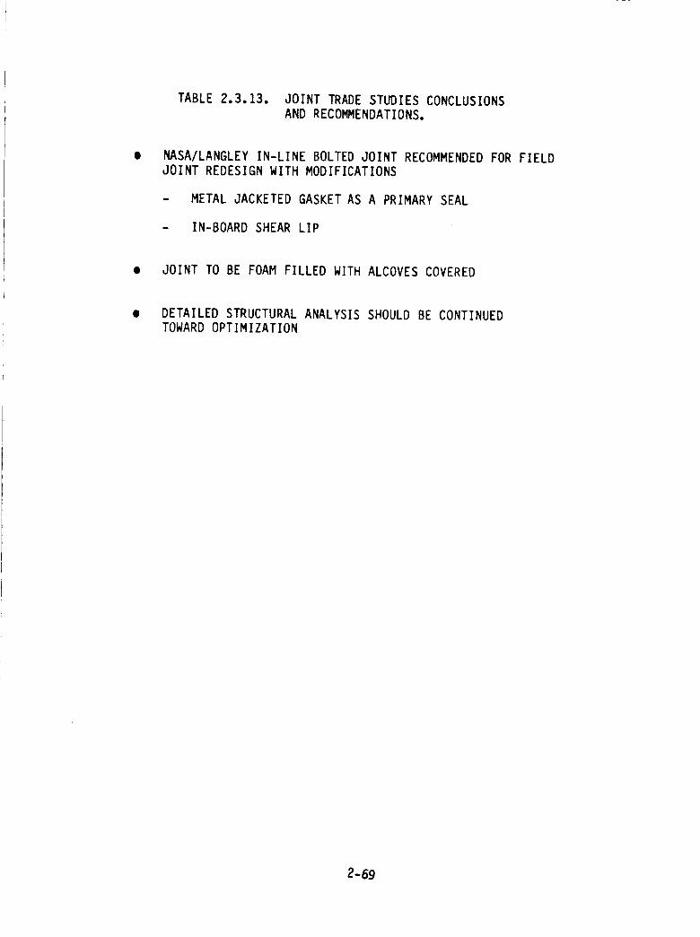
TABLE2.3.13. JOINT TRADESTUDIESCONCLUSIONSANDRECOMMENDATIONS.
NASA/LANGLEYIN-LINE BOLTEDJOINTRECOMMENDEDFORFIELDJOINT REDESIGNWITHMODIFICATIONS
- METALJACKETEDGASKETASA PRIMARYSEAL
- IN-BOARDSHEARLIP
• JOINT TOBE FOAMFILLEDWITHALCOVESCOVERED
DETAILEDSTRUCTURALANALYSISSHOULDBECONTINUEDTOWARDOPTIMIZATION
2-69
2._.1 FABRICATION PROCESS TRADE STUDY
The large-scale of the Shuttle SRM's presents processing problems that are
not commonly confronted in smaller scale rocket motors of similar design. These prob-
lems cannot only effect cost and schedule, but may also raise questions regarding qual-
ity. The manufacture of a reliable insulation on or near schedule will require a process
method that is physically feasible for the types of insulations that are currently available
to replace the asbestos filled NBR. Because the process plays a major role in the quality
and reliability of a SRM insulation, a trade study was conducted to rate a variety of
state-of-the-art processes that could be used to manufacture viable insulation candi-
dates.
The processing methods were rated on their I) potential to reproduce a reli-
able insulation, 2) the performance of the materials processible by that method, and 3)
the cost advantages/drawbacks. The weighting factors for this rating criteria are 75%
for reliability, 1596 for performance, and 1096 for cost. The processes were rated on a
scale of I through I0, with 10 being the highest rating. The fabrication processes select-
ed for the trade are listed and rated in Table 2.4.1. Included are the characteristics of
uncured polymer binders that are processible with each process. Of these processes, the
automated (ribbon winding) lay-up process was given the overall highest rating and is
proposed as the prinicpal processing method of the SRM insulation.
The automated lay-up process consists of a computer controlled extrusion-
winding operation. This operation, graphically displayed in Figure 2._.t lays an extruded
ribbon of insulation into the case as the case is rotated. A premixed gumstock is fed into
a single screw extruder and extruded into a ribbon of a controlled temperature which
provides good tack and pliability without scorching the rubber binder. The ribbon is
transferred from the extruder along a rotter conveyer arrangement and positioned on to
the case by a rubber applicator wheel. This applicator applies pressure to the ribbon
during lay-up by a pneumatic control to ensure that the ribbon lay-up simulates that of
shingles, where one strip partly overlaps the prior strip, the applicator moves axially
within the case as the insulation is wrapped. The thickness of the insulation can be
controlled by varying the axial speed with respect to the angular speed of the case; e.g.,
to thin the insulation, the applicator is moved along the axis at a greater rate so there
are less ribbon overlaps. The opposite is done to thicken the insulation. To provide tack
between the case and ribbon, the case wall will be coated with a film of the insulation
2-70
iI'e'la.I
OW
0If)
Ca_LLI
Q
ZQ
U.
W.-Je_
X C._ I
LL-
_._--_-'_ I
w(..)CD
z
I,iI
(J
Q
X
Q
Z
t_J
N
z-J _.
-l'z I
I -'_
Z _" F'- ,-,'_
"r" ._,l c:C ".--,"
r_
_D
c:C,'-_
I'--.--_r,,)_,,,,
r_
r,)
_)
z
,_1QX
ZQ
I--c...)w
Z
m
w(_ml",=:co
I
Ut-_
Z
Z
Z
.,-.,W
z_-._-_=C
-.lr-_'-_ZC,__z
l.i.II--
W-.I
Zl.=-I
Z
_i4
e_
i
._I
wF.-
F--
2-71
L_J
0
C1.
I>-
-.J
Z0t.-,tt--
._I
v')Z
Z
!
Z
0
LulI*--
I.--
W
2-72
binder by a spray-on application. This is conducted by spraying on the solvenated binder
and allowing the solvent to flash off. As in the current process, the case will first be
coated with a primary, co-curing adhesive before the tack coat and insulation are
applied. The automated process will also be used to lay-up designated inhibitor flaps.
The insulation will be bagged for autoclave cure, as conducted on prior flight motors
except that a one-piece butyl rubber bag is recommended, over the nylon bagging film, to
minimize vacuum bag leaks during autoclave cure. The final step will be to cure the
ribbon wound lay-up in an autoclave to net-shape.
The automated ribbon winding lay-up process was given the highest scores in
each category of the rating criteria. This process was given the highest rating in the
reproducibility/reliability category. This is mainly due to the computer controlled opera-
tion, which greatly increases the redundancy of operation while reducing intensive labor
and eliminating the use of the solvents to activate tack during lay-up. The latter two
factors are the primary problem with the semi-mechanized lay-up operation used to build
SRM insulations to date. Another advantage of the automated lay-up process is that the
void content in the lay-up is minimized due to the increased tack of the freshly extruded
ribbon and the controlled pressure from the applicator wheel on the ribbon during lay-
up. The extrusion operation eliminates the need for calendering stocks which broadens
the scope of materials that can be considered. Many of the high performance asbestos-
free insulations have inherently poor tack at room temperature and do not calender well_
however, they are readily processible by an extruded ribbon winding process. In addition,
prepreg fabric materials may also be considered for wind processing. Although the
capital costs of the equipment is moderately high, the technology behind the equipment
is not only advanced but proven. Extruded ribbon winding operations are currently used
to manufacture a variety of rubber products, from tires to rocket motor insulations.
Start-up (after equipment procurement) and qualification tests would require several
months' effort; however, this process method is extremely cost effective based on its
high output rate and its expected low attrition rate.
The Hand Semi-Mechanized lay-up process technique was used to build SRM
insulations to date. Of the processes rated this operation is the most labor intensive.
Other problems are that it is a slow process, and solvents are often used to activate tack
on calendered stock. Aside from these, the material selection would be somewhat more
limited than the automated lay-up process because calendered stock is required. Costs
would be slightly higher than the automated process mainly due to the additional labor
2-73
involved in calendering, and hand lay-up. Aside from these problems, the hand semi-
mechanized process was rated number 2 overall.
A casting process was also given a high rating, but not the highest due to the
higher potential of voids to occur in the insulation. This could be a serious problem
because it is very difficult to accurately x-ray insulations on the case. The material
selection of castable insulations is limited. A major problem with this process is the
tooling costs and the complexity of equipment that would be required to pump, or cast
insulations between the case and the casting tooling over the segment length.
Bonding in a cured insulation would use the automated lay-up process except
the insulation would be layed-up on a mandrel and cured, machined, and then bonded into
the case. This process features some notable advantages, such as full X-ray inspection
capability and greater ease in processing; however, the bond integrity would always be in
question due to the difficulty in loading the insulation into the case. Injection molding
and sling lining, although optimal processes for many end products, would be impractical
for an insulation of this size and dimension.
2.4.2 CASE INSULATION TRADE STUDY
ARC conducted an insulation trade study to find a non-asbestos replacement
for the NBR/asbestos/silica insulation. The study was divided into two parts. The first
step was a review and selection of binders and fibers. The selected binder/fiber combi-
nations were then evaluated in a detailed trade study.
The binders that were considered for insulations are listed in Table 2.4.2.
Three areas, specific gravity, thermal conductivity and ARC/industry data base were
considered important for the binder selection. Four binders have a specific gravity lower
than the baseline NBR and there is an established data base on SBR, EPDM, polyisoprene
and polybutadiene. All of the binders have equivalent or lower thermal conductivities
than NBR. For the binders being considered, Hypalon has the lowest thermal conductiv-
ity. Of the seven binders listed with an established data base, ARC considered NBR,
Hypalon, SBR, EPDM, and polyisoprene to be the best for consideration in the detailed
trade study.
2-74
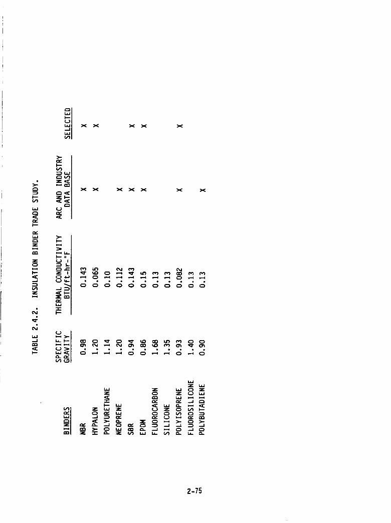
X X X X X
>:¢:3
l--
la,J
'¢E
I'--
laJ
Z(:3I,-,,I
I..-
,=;
z
o,1,=:o,;i,.iJ._J
¢¢I,--
_==<
up,,.¢¢
x X x x x x x
>_o':-
-_1 ° ° ° ° ° ° '=; ° ° ':;':;,,=,
° 0
u
IJJz
w z la.J ° zz 0 z (..3 L=J
-r. ev. ,-v" .,.,II_ u.J ,¢E _ et _ ,¢E
"_ ),- 0 I._ _ _. _.J ,--t 0 .-I 0z .,i- _. z _1 I._ 14. (/) cL. 1.1. Q.
2-75
There were many different types of organic and inorganic fibers considered
for replacing the asbestos. The fibers are listed in Table 2.4.3. None of the inorganic
fibers can be processed in standard rubber mixing equipment, such as a banbury or a mill,
without severe fiber damage or breakage. Fiber breakage will reduce the char strength
of the insulation. The only inorganic fiber considered for the detail trade study was
carbon. A carbon/EPDM insulation which is manufactured using a solvent process is cur-
rently being used in the shuttle. Two organic fibers, Kevlar and PBI, have primarily been
used in the industry as asbestos replacements. Based on ARC's experience, Kevlar per-
forms better than PBI. Also, ARC has experience with a cellulose fiber that provides
good char and acts as a coolant when it decomposes. Therefore, Kevlar was chosen as
the primary fiber for replacing the asbestos and two formulations will be considered with
the cellulose and carbon fiber.
The detailed trade study was divided into three areas_ reliability, weight and
cost. The trade study is given in Table 2.4.4. The weighting factors for three areas were
75 percent for reliability, 15 percent for weight and 10 percent for cost. Reliability was
sub-divided into four areas: thermal (2596), manufacturing/processing (3096), compatibil-
ity (10%) and mechanical properties (10%). The thermal area was divided into material
affected rate (MAR) and thermal protection. MAR was given a higher weighting factor
because of the requirement of a 2.0 safety factor. Manufacturing/processing was divided
into four areas. Viscosity/scorch was rated the highest because of the need to 1)be
extrudable, and 2)have uniform cure/properties throughout the thickness of the materi-
al. Green tack and ribbon integrity were rated the next highest, respectively, because
once the material is extruded it must stick to itself to provide a uniform lay-up, mini-
mized air entrapment and provide a controlled process. Compatibility was divided into
vacuum outgassing and aging with the latter given a higher weighting factor. Mechanical
properties were divided into bond, strain and modulus. Bond was given the highest
weighting factor in order to maintain compatibility with the current liner. Cost was sub-
divided into recurring and non-recurring. Recurring cost was given a higher weight
factor than non-recurring because it is the material cost. Non-recurring is the equip-
ment cost which will be about the same for all of the materials.
The candidate materials (binder/fillers) are also given in Table 2.4.4. Ten
candidates plus the control, NBR silica/asbestos were evaluated in the detailed study.
The best three insulations in the area of reliability were USR-3g00, EPDM Kevlar/
cellulose/silica, and Hypalon silica/Kevlar. The primary reason for their high reliability
2-76
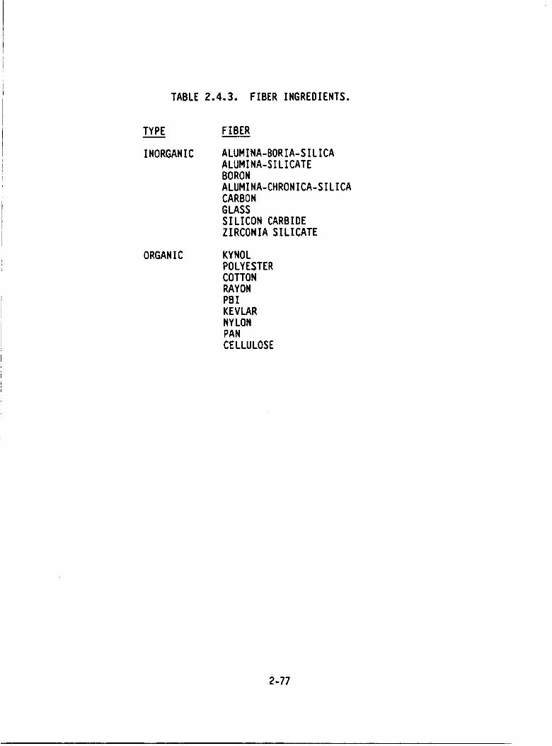
TABLE 2.4.3. FIBER INGREDIENTS.
TYPE
INORGANIC
ORGANIC
FIBER
ALUMINA-BORIA-SILICA
ALUMINA-SILICATE
BORON
ALUMINA-CHRONICA-SILICA
CARBON
GLASS
SILICON CARBIDE
ZIRCONIA SILICATE
KYNOL
POLYESTER
COTTONRAYON
PBI
KEVLAR
NYLON
PAN
CELLULOSE
2-77
F--Zco) _-,
,,,<_
c_cos ..J
Z _-OL_
--J_L._C_F--Z_
V) Zc_c_CO{..)
i,i
.--J
2-78
rating is due to thermal performance. The candidate with the least reliability was an
EPDM silica. The best three candidates for weight were EPDM carbon fiber, EPDM
silica and EPDM silica/Kevlar. All of these have an EPDM binder which has the lowest
specific gravity. All the candidates were close on cost except for the EPDM carbon fiber
which is the most expensive because of the solvent process used in manufacturing the
material. A diagram showing the overall ratings for each of the candidates in the three
categories is given in Figure 2.4.2. The best three insulations are Hypalon silica/Kevlar,
USR-3800 and the EPDM Kevlar/cellulose/silica. Design studies using these materials
are presented in Section 3.4.L.
2._ PROPELLANT TRADE STUDIES
The objective of this task was to improve SRM performance and reliability
via propellant, liner, and igniter propellant formulations. The constraints set for the
selection process were existence of a solid data base, retention of the thrust-time trace,
unchanged or improved variability, maintained structural margins, a 0.364 in/sec burning
rate requirement (625 psi), and asbestos elimination. These issues are summarized in
Table 2._.I.
An examination of available propellants quickly eliminated the higher per-
formance aluminized Class l.i propellants because of the increased hazards, and the
alternate or nclean" propellants based on ammonium nitrate because of performance
degradation and their not yet being state-of-the-art. The trade candidates were there-
fore limited to a PBAN formulation such as TPH-LI_g in the SRM and an improved
performance HTPB propellant. The evaluation factors were heavily weighted for
reliability (motor integrity, producibility, etc.) which was assigned 6096. Hazards and
payload impact were each assigned I_% with cost considerations having the least influ-
ence (iOl%).
ARCADENE 360B, the HTPB propellant used in these trade studies, is com-
pared to TPH-L L48 in Table 2.$.2. ARCADENE 360B must be slightly modified to meet
the burning rate requirement by reducing Fe20 3 percent which becomes very similar to
that used in TPH-LL48. ARCADENE 360B has been extensively characterized over a
wide range of burning rates. Atlantic Research Corporation (ARC) has produced over
28 million pounds of this propellant at our Camden, Arkansas facility. The current
production rates for the Vought MLRS program is over 70,000 Ibs/day, making it one of
the most produced propellants in the world.
2-79
IN,. &O
CD CW
WZ
;<
ed e'}i,,i.
,,,. IN,,
IN,.
(#J
O 'I" ,,.iui f_
,_,f,l'j
a:o .(2
:::I'IVOS 9NLLVl=I
I---
r._i.-.w
r_Z
(...)
Z0
I---
--J
.-_b*')z
LI-
(:3
_Ot_O
I---
2-80
l---
,,J
e_
r_
Zi--i.--I
rmZ
Z
.--I--.IILl
0
O.
l.l.J-.I
_CI---
A
Zol--1
00.
00
A
A
n- ILl ILlILl
Z '" rrl-r o.
_o oI_I l.IJ --
Ore N _- '
Z_
_ _ _zzz_z -_a.
0 0 "''''" _ "'"
2-81
TABLE 2.5.2. PROPELLANT FORMULATIONS.
TPH-1148 ARCADENE 360B
BINDER PBAN/EPOXY R-45HT/IPDI
Fe203 0 - 0.3% 0.1 - 0.3%
AL POWDER 16% 18%
TOTAL SOLIDS 86% 88%
AP (COARSE/FINE) 70/30 70130
(i-2_ 2-82
Table 2.5.3 summarizes the trade studies showing slightly higher rating for
the current PBAN propellant, primarily because of demonstrated reliability in numerous
flights and full scale motor firings in which a problem or malfunction due to propellant
has never been identified to our knowledge.
ARCADENE 360B outscores the PBAN propellant in all other categories
except for initial non-recurring costs for D&V to qualify the propellant in full scale SRM
motors.
However, in the event that higher performance (payload) is required, ARC
offers a very credible approach with ARCADENE 360B with a vast database and produc-
tion proven reliability and producibility.
More details of the trades in each category follow.
Propellants are compared for producibility and reliability in Table 2.5.4.
In assessing the trades, scores of I to I0 were assigned with 7 being the norm
assumed for TPH-IIAg unless a deficiency existed. ARCADENE 360B has not been cast
and fired in an SRM motor and therefore lacks the full-scale demonstration. This is the
primary reason for the lower score. In terms of propellant produced, 28 million is less
than 70 million but the difference is not significant since both numbers are very large.
The gap will close rapidly as 360B production for MLRS continues. The 360B mechanical
properties are superior to any PBAN propellant and can be tailored for higher strain.
Although not required in this motor, 360B mechanical properties are significantly better
at low temperature.
An asbestos fire-free liner must be formulated and demonstrated for both
propellants. The insulation composition will affect the liner selection. An asbestos-free
liner (ARL-151) has been demonstrated with ARCADENE 360B but may require some
modification for the SRM application.
Table 2.5.5compares propellant hazards.
Both propellants exhibit similar hazard characteristics typical of state-of-
the-art Class B (military 1.3) composite formulations. ARCADENE 360B is rated slightly
better for exhaust products based on its slightly lower CO concentration.
2-83
....J
1.4.1
l'--c,O
I..I.IE_
I--"
e_
,-_I
E_
I'--Z
.--I-,.I
O
,.,-;
-..I
I--
2-,94
TABLE 2.5.4. MOTOR PRODUCIBILITY AND RELIABILITY TRADE
(PROPELLANT LINER).
PARAMETER TPH-1148 SCORE ARCADENE 360B SCORE
FULL-SCALEMOTOR
DEMONSTRATION
YES 7 NO 1
QUANTITY OFPROPELLANT
PROCESSED (LB)
>70 MILLION 7 > 28 MILLION 6
MECHANICALPROPERTIES
$em (psi) 113 7 170± 10
m (%) 37 35 + 5
E° (psi) Sle coo±loo
BURNING RATE <2% :1:1%ON MIXESREPRODUCIBILITY DIFFERENCE 7 WITHIN LOT
FROM TARGET7
PROPELLANT EXTENSIVE 7 EXTENSIVE 7DATABASE
YIESWITHASBESTOS-FREE NO 4 MODIRCATION 4
LINER
PROPELLANT/LINERBOND
(NO ASBESTOS)
4 UNKNOWN
D & V MINIMAL 7 SUBSTANTIALREQUIRED EFFORT REQUIRED
TOTAL SCORE 50
AVERAGE SCORE 6.3
4
1
37
4.6
2-85
UJ
U)
e'J
N
-I-
Z
..JLJJ
O
_4LO
_J
LJJ--J
I--
o¢o
UJZUJ
.¢0rr ¢00n
odd
I.Un-O0
h- o
I-A
(/)
n-UJ
UJ
tr
2-86
The ARCADENE 360B performance advantages are clearly shown in
Table 2.5.6. Specific impulse and density are both higher for ARCADENE 360B. The
25,175 propellant weight is calculated only from the density difference in the HPM Motor
Design. A 2000 lb. extra insulation penalty was assumed for the higher flame tempera-
ture of 360B. Using a 1.2 g/cm 3 assumed insulation density, this converts to a 22,340 lb.
additional 360B propellant. Using the assigned influence coefficients, a +Its90 lb. payload
is calculated. This figure does not include any additional thrust contribution from the
higher theoretical specific impulse of 360B since some efficiency loss must also be
assumed from the extra 296 A l.
The primary requirement for the liner is to reliably bond the propellant to the
insulation. Secondary requirements are environmental and process. It must also be
asbestos-free. It must have a reasonable pot life for application, it must stay in place on
application to vertical insulation, and it must bond to propellant after being held at the
cure temperature for a 30-hour casting period. All the requirements are met by the
current system except the asbestos-free one.
The trade summarized in Table 2._.7evaluates a minimum change (Option I)
in which the asbestos is replaced by another fibrous filler against a change (Option [I) in
which filler, polymeric composition, and other ingredients may be changed. The strongly
weighted reliability criterion forces the trade results to Option I because it offers mini-
mum change to the current system. Option II allows a potential payload increase from an
estimate of weight savings which result from a decrease in liner thickness. Decreasing
the current .057" to .020" corresponds to a decrease in weight of 1,000 pounds per SRM.
If the volume lost were filled with propellant, a payload gain of 296 pounds would result.
Thin liners are a strong point in ARC motor technology. These thin liners
frequently owe their success to internal barriers,
The existing shuttle rocket motor liner is based on Minuteman technology in
which the liner also played a signficant role in insulating the case.
2-87
TABLE 2.5.6. PROPELLANT PERFORMANCETRADE (HPM MOTOR DESIGN).
PARAMETERI
oIsps
(Ibf-sec/Ibm)
I I I i
DENSITY
(Ibm/in3)I
VOLUMETRICSPECIFICIMPULS_(Ibf-se¢/i_)
I !
VACUUM SPECIFICIMPULSE
(Ibf-sec/Ibm)I
PROPELLANTWEIGHT (Ib)(NO INSULATIONCHANGE)
INCREASE ININSULATIONWEIGHT (Ib)
i
NOT INCREASEIN PROPELLENTWEIGHT (Ib)
I
PAYLOAD (Ib)I
SCORING RANK
TPH-1148
261.9
0.0635
i
16.63
268.5
1,110,136
I I
I
|
7m
+ 0.083 (22,340) - 0.182 (2000) = 1490
'ARCADENE 360B
263.1
0.0650
269.7
1,135,311
II
2,000
Io
6I
+1.2
+0.0015
+0.46
+1.2
+25,175
+2,000
+22,340
+1490"
2-88
TABLE 2.5.7. LINER TRADE.
FORMULATION
VARIATION
EXISTING
FORMULAT I0N
CHANGE ONLY
FIBROUS FI LLER
CHANGE MAIN INGREDIENTS
AND FIBROUS FILLER;
POSSIBLY USE BARRIER
ADVANTAGES HIGHLY RELIABLE BONDING TO V44 &
TP-H1148 ESTABLISHED ;
AGING BEHAVIOR KNOWN
MAY BE REQUIRED TO BOND
TO NEW INSULATION;
BARRIER ALLOWS WEIGHT
SAVINGS
PAYLOAD (+296 Ibs)
DI SADVANTAGES NOT ACCEPTABLE
DUE TO ASBESTOS;
THICK LINER
CAUSES INERT
WEIGHT PENALTY
NEED TO DEFINE
PROCESSI BILITY &
CURE CHARACTERI STICS,
AND VERIFY BONDLINE
PERFORMANCE
EXTENSI VE TESTI NG
REQUIRED TO QUALIFY
NEW SYSTEM
RATING CRITERIA
WEIGHTED
SCORE VALUE
WEIGHTED
SCORE VALUE
RELIABILITY 7 4.20 4 2.40
HAZARDS
PAYLOAD IMPACT 7 1.05 8 1.20
COST 7 0.70 4 0.40
TOTAL 5.95 4.00
2-89
2.6 NOZZLE TRADE STUDIES
2.6.1 INTRODUCTION
The primary goal of the nozzle portion of the Block II study program is to
significantly increase the reliability of the nozzle assembly and attachments by utilizing
well developed state-of-the-art technologies. A secondary goal is to increase motor
performance so as to offset weight penalties incurred in maximizing the reliability of the
overall motor design, when this is consistent with the primary goal. The approach chosen
to accomplish this is based on retaining the existing nozzle concept. This means every
attempt will be made to minimize the impact on the flex bearing, the nozzle flow
surface contour, and the TVC system. The existing metal parts will be used if possible,
but where changes are necessary, minimum impact on forging dimensions will be
attempted. The nozzle study will, therefore, investigate alternative design approaches
where justified according to the following criteria:
Where there is a demonstrated problem area requiring an improvement inreliability/ flight safetyl
I£ an existing technology can be incorporated that improvesreliability/flight safety or increases performance with no loss inreliability/flight safety;
• If the Block II SRM design dictates a nozzle design change.
Based on this approach, it was decided to concentrate the initial effort on
trade studies for the nozzle-to-case attachment joint and the nozzle liner material. The
joint study considers both the metal hardware and the insulation with emphasis on the
sealing aspects of the assembly. Alternative inlet/throat liner materials are being
investigated primarily to further reduce or hopefully eliminate the potential for
_Ocketing" erosion such as that experienced on STS-8. These studies are discussed and
preliminary results are presented in this interim report. The hardware joint study is
included in this section, while the insulation joint study is in the insulation section.
Also discussed, in Section 3.3 of this report, is a design study conducted for
the five nozzle subassembly joints which currently have simplex seals. Alternative
2-90
designs were investigated which meet the Block It redundancy and verifiability
requirements. All the data necessary to complete these studies have not yet been
generated. However, the progress to date is reported and the anticipated choices are
indicated for the purpose of providing a preliminary design. In addition, studies are also
being conducted in several areas which are not addressed in this interim report. All
asbestos-containing materials will be eliminated from the Block It design. Replacement
materials will be found for the several adhesives and gap fillers used in the nozzle
assembly and the elastomer used in the radiation shield. Since a design change is
required, alternate concepts for the radiation shield will be considered. The use of
improved liner materials will also be investigated for all areas of the nozzle. The
complete results of all these studies will be fully documented in the final report.
2.6.2 NOZZLE-TO-CASE 3OINT HARDWARE
This section presents the resultscompleted to date and a status of the trade
study on the SRM Nozzle-to-Case Joint hardware (herein called the NTC3). Three
alternate NTC3 concepts were selected as possiblecandidates. These candidate designs,
along with the current redesigned NTC3, willbe rated according to a set of evaluation
criteriain order to select an optimum NTC3 design.
A preliminary design has been selected based upon the work completed to
date. The final selection will be made once the trade study has been completed.
The objective of the trade study is to improve the reliability of the NTC3
design. An emphasis is being placed on the sealing mechanism of the NTC3 design in
considering any improvement in the reliability.
The critical objective to improve the reliability is to obtain a sealing
mechanism that would be independent of (or not highly effected by) the response of the
NTC3 to the required loading conditions or the manufacturing process. This will be
accomplished by both making changes to the hardware configuration and changing the
position of the primary and secondary seals.
The three alternate NTC3 designs, along with the current baseline redesign,
are shown in Figure 2.6.1. These new design concepts shown in the figure are the I) dual
face seal, 2) shear retention lip, and 3) capture latch.
2-91
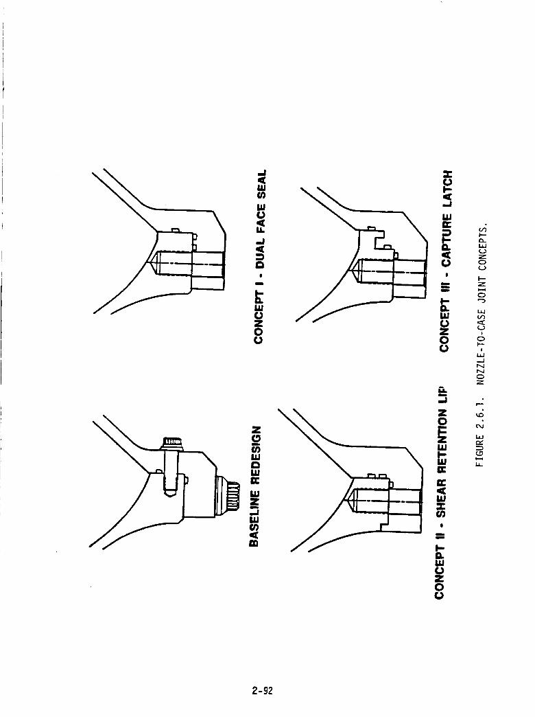
a.I.iJC)Z0(.1
I---
_-0_._
0
i0I'--
i
-.J
0
I.L
2-92
The dual face seal concept is similar to the original NTC3 with one major
exception, the primary and secondary seals are now both face seals. The width of the
flange mating surface was increased to accommodate the second seal. Since no bore seal
is involved, extremely close radial tolerances are not required.
The shear retention lip concept is a two-seal type configuration; utilizing
both a face and a bore seal. A shear lip has been incorporated on the nozzle component
of the NTC3. This feature minimizes the relative radial motion between the nozzle and
case flanges ("rounding"). This rounding is a major contributor to gap opening. In
addition, the primary seal has been moved in an attempt to make the seal gap less
dependent on joint rotation.
The capture latch concept is also a two-seal type concept, and has
interlocking tabs on both the nozzle and case components in order to reduce gap opening
due to "rounding." These tabs also serve to reduce gap opening due to joint rotation.
Each of these concepts also have some disadvantages associated with them.
A description of the advantages and disadvantages associated with each concept is shown
in Figure 2.6.2. All three configurations utilize a third seal, so that the primary sea!
[unction can be verified in the direction of operation.
The evaluation criteria to be used are summarized in Table 2.6.l. As shown,
it consists of three areas, namely; reliability, performance, and cost. These three areas
were selected due to their importance to the NTC3 design. The relative emphasis of the
three criteria in the design is shown by their weighting factors. The reliability has
obviously been assigned the highest weighting factor. The motor performance rating will
be based on inert weight impact. Cost evaluation will include the impact of new forging
tooling if this is required.
The reliability of each of the concepts will be estimated by the use of finite
element analysis and conventional strength of materials analysis. The performance and
cost criteria will then be evaluated once a reliable structural design has been
determined.
Concept I has been selected as the preliminary design (Figure 2.6.3). The
main advantage of this design over the other concepts is that it is not as complex. In
2-93
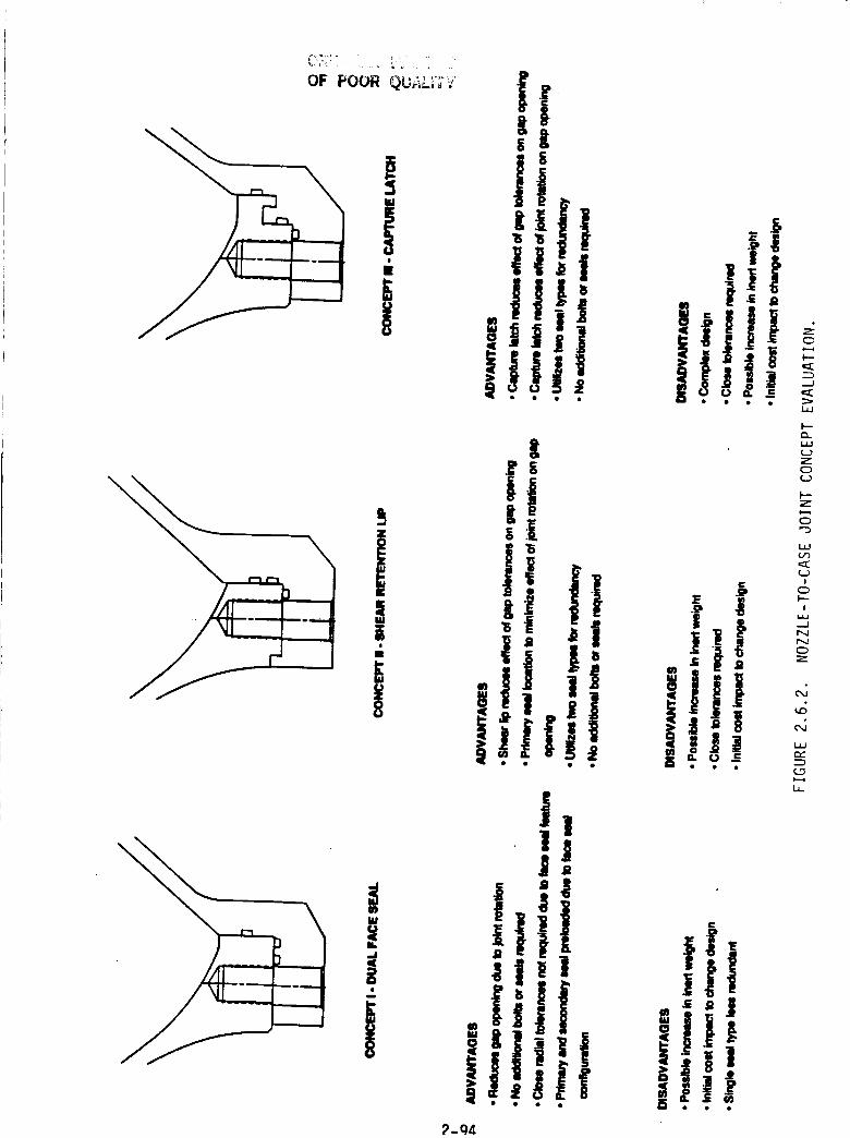
II!
OF POOR QUALiT¢ I ._'-
| t
I .lil ,I!!!, i
g
" ! Iili I +
i,,&,,.
i1
I +'" Ii!! '!I"
I!+!!_ i!!!?_Q,_
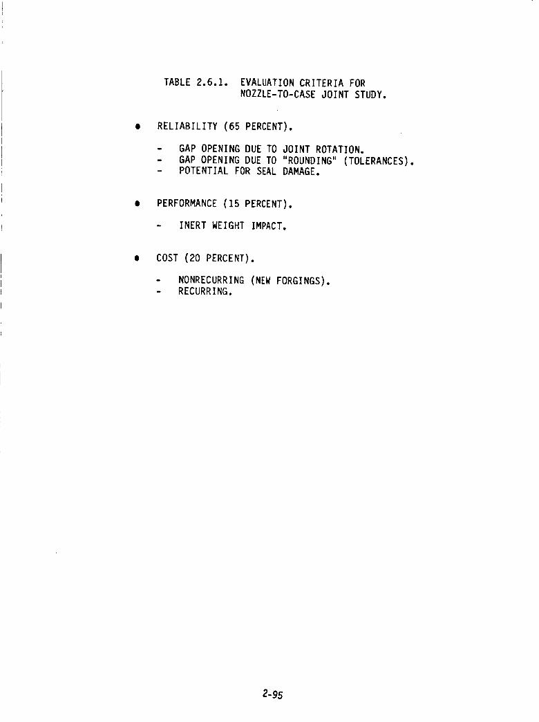
TABLE 2.6.1. EVALUATION CRITERIA FOR
NOZZLE-TO-CASE JOINT STUDY.
RELIABILITY (65 PERCENT).
w
m
GAP OPENING DUE TO JOINT ROTATION.
GAP OPENING DUE TO "ROUNDING" (TOLERANCES).POTENTIAL FOR SEAL DAMAGE.
PERFORMANCE (15 PERCENT).
- INERT WEIGHT IMPACT.
COST (20 PERCENT).
- NONRECURRING (NEW FORGINGS).- RECURRING.
2-95
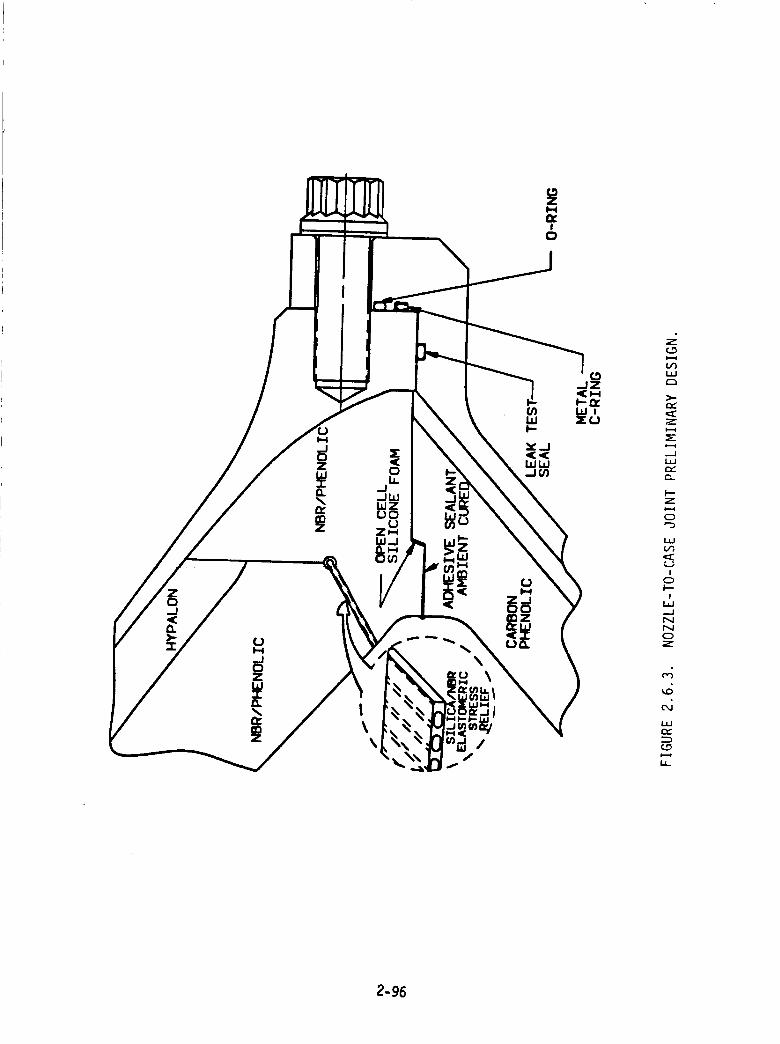
(.D
ILl
Z
1.1J
I--z
o"-3
i
I
-.JNN0Z
1.1J
ty
2-96
addition, the manufacturing and
dimensional tolerances required).
Concept I.
assembly of the NTC3 is simplier (not as close
The final design chosen will probably be similar to
The trade study, as far as performance and cost is concerned, still needs to be
completed. Once this has been completed and a final design selected, an in-depth
structural analysis will need to be done to ensure the structural integrity of the NTCg.
This analysis will have to take into consideration the preload on the bolts, dimensional
tolerancing, and required loading conditions in order to properly establish the NTC3
reliability, i.e., seal mechanism.
design,
Final performance and cost numbers will also be generated for the final
2.6.3 NOZZLE THROAT LINER MATERIALS
Liners used on the current SRM nozzle (Figure 2.6.4) are fabricated from
rayon-based carbon cloth/phenolic tape. The performance of this liner material has been
adequate with the notable exception of anomolous gouging and "pocketing" erosion, which
was first noted in the STS-gA nozzle forward nose ring and aft inlet ring, as shown in
Figure 2.6.4. The nozzle inlet liners on this motor and several subsequent flight motors
have failed to meet the 2X requirement on erosion. NASA and the current nozzle
fabricator have spent considerable time and effort studying this problem, and as a result
of stringent material and processing controls and revised processing techniques, have
virtually eliminated the incidence of pocketing erosion in the last six successful flights.
However, although a number of items have been identified as potential contributing
factors, the problem is not considered solved since the failure mechanisms are not fully
understood, and several studies are still underway to evaluate all facets of the rayon-
based material's manufacture and response to the operating environment which migh_
relate to the problem.
The Block II study program offers the opportunity to investigate more
extensive changes to the inlet/throat liner (Figure 2.6.5) than have previously been
considered to solve the pocketing erosion problem. Therefore, a trade study was
initiated to evaluate two types of material changes. The first is a direct substitution
where liners would be fabricated using the existing tape wrap techniques but with a
2-97
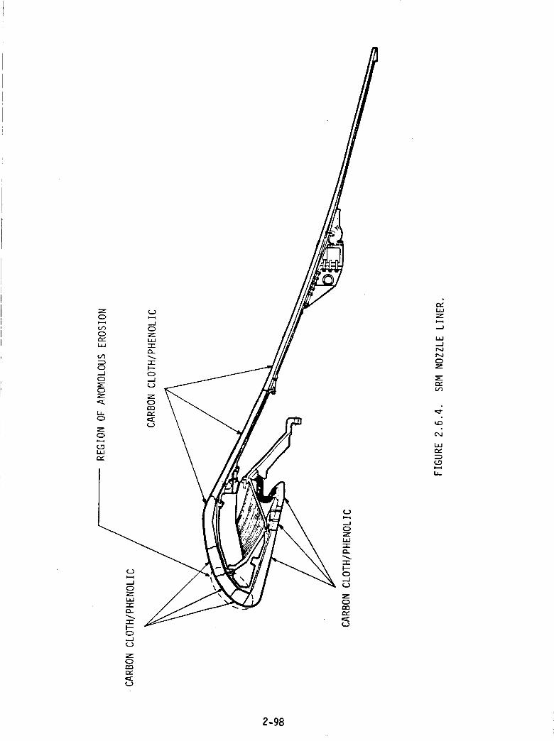
Z0
(J30
ILl
¢J3
--I
_--
Z
LL.C_
Z
0
L_
¢_)
--J0ZLI.J
-rI---0..--I
Z
0
,=_
(..)
.--I0ZILl"I"
-r"I--"0--=I
Z
0
2-98
f..)
.-J0Z
'-l-
-r"I--0..J(..3
Z
0
Z
ILl
r._N0Z
.4
i,
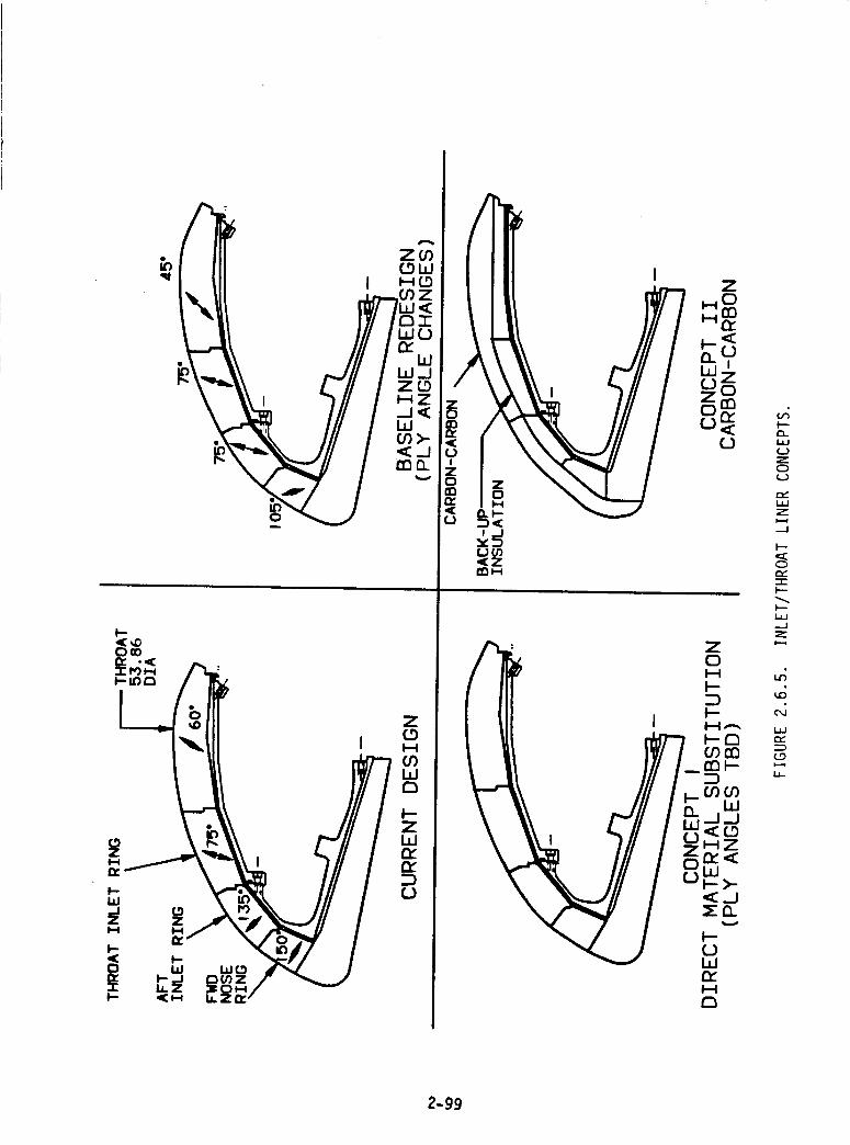
_,,4DC) eO
I'--
ml"
zI'--I
r'_
ry
f,,J
[JO0_Z
!--.
U,J
ZC)
n,,,,uJzi=.-¢,,_1
I.--
C>¢-,,,,"I'-I--
I--
..J
i.-.4
,,r;
¢,,,d
L_,-,,,.
c....oi.-=1LI-
2-99
different material, while the second is a more extensive material change requiring a
different fabrication technique. Several test programs evaluating alternative tape
wrapped ablative liner materials were conducted prior to the STS-8 flight. The materials
tested there were considered as potential candidates of the first type since measured
erosion, char, and thermal performance data existed relating to SRM usage. These
ablatives included polyacrylonitrile (PAN) based carbon cloth/phenolic and PAN or pitch
based graphite cloth/phenolics. Since tests and analysis conducted as part of the STS-8
investigation indicated that graphite cloth/phenolic or PAN based materials offered
increased resistance to pocketing erosion, these were chosen as the ablative materials to
be included in this trade study. However, in many of the rocket motor nozzle designs
currently being produced or developed, tape wrapped ablative liners have been supplanted
by multidirectionally reinforced carbon-carbon materials for the inlet/throat region.
While the data base for this relatively new class of materials is not yet as extensive as
that for the tape wrapped ablative materials, it is rapidly growing. The inherent three
dimensional strength of these materials would virtually eliminate pocketing erosion, and,
therefore, carbon-carbon was included as the material of the second type. For the pur-
poses of this initial evaluation, 3-D carbon-carbon was taken as typical of all
architectures.
Table 2.6.2 gives a summary of the advantages and disadvantages for each of
the three nozzle liner materials. As shown, all three appear to offer increased resistance
to pocketing erosion. However, if any of these materials were chosen for a Block II SRM
design, an extensive materials test program would have to be conducted to verify these
characteristics and their reproducibility. All three also offer increased motor
performance due to decreased erosion. Carbon-carbon offers the highest gains in both
these areas, but also requires the most development. There are several significant issues
associated with utilizing carbon-carbon in this application. Thermal requirements and
physical constraints lead to a radius/thickness ratio I R) between 20 and 40, which is
outside the region of current designs. Buckling due to restraint of the high temperature
carbon-carbon liner thermal growth imposed by the low temperature steel housing
becomes a concern. This could be aggravated by high backside pressure buildup if a
degradable (charring) backup material such as carbon/phenolic is used, and gases due to
pyrolosis are not adequately vented. Nondegradable backup materials are becoming
availablel however, their lower insulation properties would lead to higher housing
temperatures at soak out unless overall liner/insulation thickness is increased.
Evaluation of the carbon-carbon approach requires a more detailed design study than has
2-100
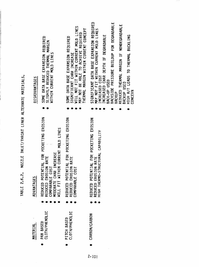
,X._1
1",=4
ev.uJI---
_r"
uJI,--
Z
I--_.1
LI.IZ
._1
I.--1=CO
'.,t-I--
i--u.I-J
u.I.._1h,JI',,IO
I.tJ.,-I
,=CI---
X
r,_
LI.I
_C,D
UJ,=_
_P ..j I,aJ0 I:_E Z
Zp,I
i,l
zo
z
z
_z
z__
ooo
z
z_
_ZZ
oooo
z
g,,,,-I
¢:)
l=IJ
zI--'4
I'---L_
r.,*"0L_
--=I
l--_w
I'--0
I.LI(...>
r,.-
L._JI--
=" I'---Ou'),-_ c:)u_ ¢.,.)On,-ujI._J ..J
i,.ij rv"¢.) ,,:::
L_JC)n,- f,,.)
OOO0 • • •
Z0
0
I.-
z ..J
L_ _
-J
h I---_
F'--O0
L_
ev" I_ "r
O oo
._1o
r"_ i..ijI.Ij "r"v) D..
nn "r"I'--
ZO
CL ¢..,_
(..)
.J_",OI_JZ
_.. ¢..)
oc_r,..
(,,.)
zo
n_
¢..)
2-'/0]
been completed at this point. It is recommended, therefore, that this concept be carried
along as an alternative through the end of the study program so that a full evaluation can
be included in the final report. The most significant disadvantage faced by any
alternative material is the overwhelming data base which exists for the current
material. It is questionable whether any of the alternative's potential benefits
overcomes this advantage in light of the requirement that any material used on the SRM
must have an extensive data base comparable to the current materials.
The final material choice will be based on a trade study conducted, as shown
in Table 2.6.3. The relative importance of the major study factors, reliability,
performance, and cost, are shown by the associated weighting factors: 65, 15, and 20
percent, respectively. Reliability will be judged primarily on the reduced potential for
pocketing erosion. Also considered will be the reproducibility of the material, and, in
particular, process sensitivity which has been shown to be a problem with current
material. Thermal margins and structural integrity will also be evaluated to minimize
the possibility of introducing any new problems. The specific aspects of performance and
cost, as shown in the table, are self-explanatory.
For the purposes of establishing a preliminary design, the anticipated
material choice was determined to be the PAN based cloth/phenolic. This material
appears to have increased resistance to pocketing erosion, based on 40 pound charge
motor subscale nozzle firings, and also has reduced throat erosion which increases motor
performance. No significant risks have been identified for this material, with the only
major drawback being the significant test program required to provide the necessary data
base. The final decision requires detail review of the referenced subscale firings and a
cost estimate for the data base test program. It appears at this time that the char depth
for the pitch based cloth/phenolic is sufficiently large to preclude it from practical
consideration. As mentioned previously, carbon-carbon will continue to be studied as an
alternative.
2-]02
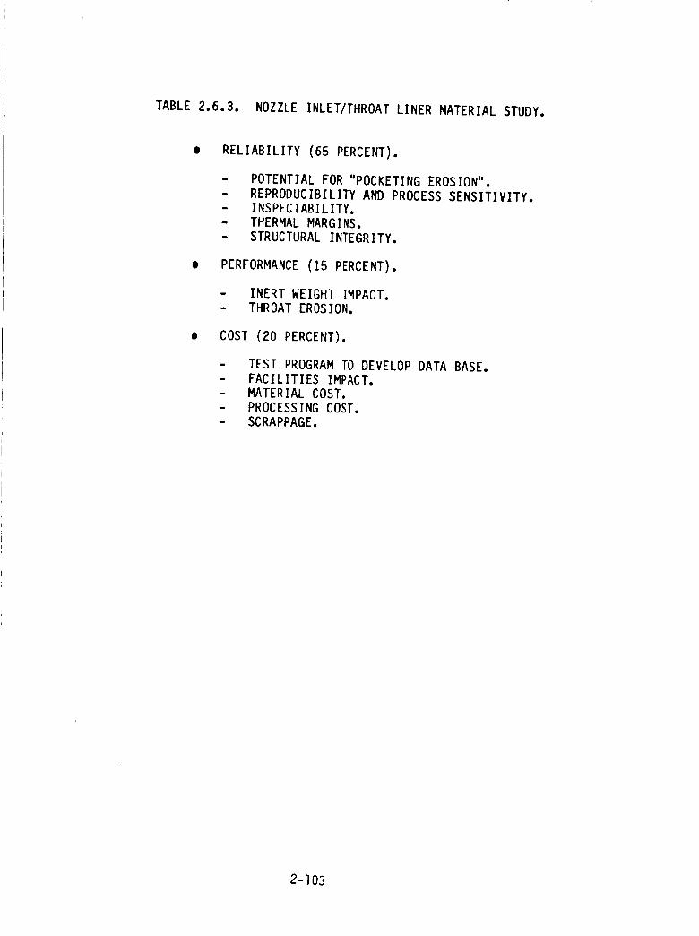
TABLE 2,6,3. NOZZLE INLET/THROAT LINER MATERIAL STUDY.
RELIABILITY (65 PERCENT),
m
i
POTENTIAL FOR "POCKETING EROSION".
REPRODUCIBILITY AND PROCESS SENSITIVITY.
INSPECTABILITY.THERMAL MARGINS.
STRUCTURAL INTEGRITY.
PERFORMANCE (15 PERCENT).
i
o
INERT WEIGHT IMPACT.
THROAT EROSION.
COST (20 PERCENT).
TEST PROGRAM TO DEVELOP DATA BASE.
FACILITIES IMPACT.
MATERIAL COST.
PROCESSING COST.
SCRAPPAGE.
2-]03
2.7 TRANSPORTATION, HANDLING AND ASSEMBLY
2.7.1 TRANSPORTATION
2.7.1.1 SEGMENTED MOTOR
The shipment of SRM motor segments presents no particular problems. The
railcarsused for shipping are already existingand would require no capitalization. ARC
assumes that the yearly usage (fixed lease)cost for each cross-country car will be
$60,000. Estimated transportation costs are;
Loaded SRM from Camden, Arkansas to KSC - $115,000/SRM
Loaded $RM from Camden to MTI/Wasatch- $140,000/SRM
Table 2.7.1 is the proposed routing for the SRM segments. These routes were based on
cost effectiveness and clearances (side and vertical). Special emphasis was placed on the
conditions of the tracks and road bed such that the transportation acceleration limits
specified for 5hurtle $RM segments will not be exceeded. This routing is only
preliminary, based on information received from the railroads' traffic managers. Minor
changes may be required to improve cost and schedule at various times.
2.7.1.2 MONOLITHIC MOTOR
Two transportation modes were considered for the monolithic motor - rail and
barge. Rail transport proved to be unsatisfactory. Rail shipping failed on several issues
including safety) cost, and regulatory issues.
The length of the motors and their attending rail cars make curves, trackside
obstacles, railyards, and traffic on adjacent tracks very difficult to negotiate. The
integrity of the cargo would seriously be jeopardized by this.
The propulsive nature of the motor is reason for concern. The estimated
range of the motor is 300 to 500 miles.
There are many regulatory uncertainties and obstacles due to the size,
weight, hazardous nature, and specia! rail cars of the monolithic motor. The estimated
2-]04
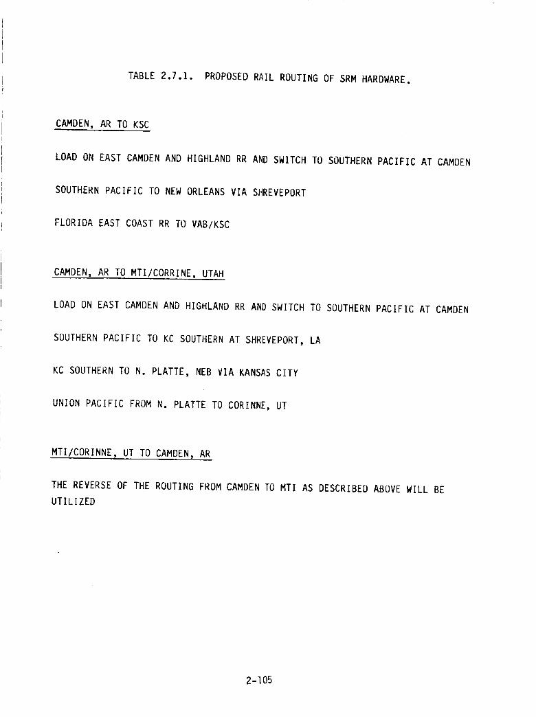
TABLE 2.7.1. PROPOSED RAIL ROUTING OF SRM HARDWARE.
CAMDEN, AR TO KSC
LOAD ON EAST CAMDEN AND HIGHLAND RR AND SWITCH TO SOUTHERN PACIFIC AT CAMDEN
SOUTHERN PACIFIC TO NEW ORLEANS VIA SHREVEPORT
FLORIDA EAST COAST RR TO VAB/KSC
CAMDEN, AR TO MTI/CORRINE, UTAH
LOAD ON EAST CAMDEN AND HIGHLAND RR AND SWITCH TO SOUTHERN PACIFIC AT CAMDEN
SOUTHERN PACIFIC TO KC SOUTHERN AT SHREVEPORT, LA
KC SOUTHERN TO N. PLATTE, NEB VIA KANSAS CITY
UNION PACIFIC FROM N. PLATTE TO CORINNE, UT
MTI/CORINNE, UT TO CAMDEN, AR
THE REVERSE OF THE ROUTING FROM CAMDEN TO MTI AS DESCRIBED ABOVE WILL BE
UTILIZED
2-I05
time to get approval of the special rail cars would be two years. This is because the
routes use more than one rail line. To facilitate rail transport of these motors would
require the acquisition (by ARC or NASA) of custom-built rail cars. Estimates for these
cars ranged from 6 to I0 million dollars apiece. Approximately l0 would be required.
In addition to the cost of rollingstock required, substantial improvement
would be necessary for the rails, rail beds, and bridges along the route. This would be a
multimillion dollar undertaking.
Waterborne transport is the only acceptable transportation mode for the
monolithic motor. Custom-made barges would be necessary. The barges need to be able
to load a rail car, dock with and off/on load to/from a Poseidon/Orion type seagoing
transport and possibly be required to provide some degree of bullet-proof protection.
Routing from Camden to New Orleans would be along the Ouachita-Tensas-
Mississippi Rivers. The barge would be off-loaded at New Orleans to a sea-going
transport similar to the Orion or Poseidon and transported to KSC across the Gulf of
Mexico. Round trip Camden-New Orleans would be an estimated 14 days. Round-trip
New Orleans-KSC would be an estimated 12 days.
Although the safety record is much better for waterborne transportation than
rail, there are still some serious safety concerns. The described route passes through
fewer population centers than rail. It does, however, pass through Monroe, Baton Rouge,
and New Orleans.
The use of water transport would require major construction at the riverside
facilities of Camden and at KSC. In addition to this port facilitization cost, rail
construction would be necessary for the approximately eight miles between the ARC
plant and the Ouachita River. The large, expensive rail cars would still be necessary.
The barges themselves would probably cost about four million dollars apiece. At least
eight would be required to keep the flight schedule. It is unclear whether the Poseidon
and Orion would be able to schedule SRM deliveries because of their ET delivery commit-
ments. If not, that would be an additional large expenditure.
A monolithic motor would require an additional test stand because the two in
Utah (one existing, one proposed) could not be accessed by barge. A likely site would be
Complex 37 or Complex 34 at KSC.
2-106
2.7.2 HANDLING
2.7.2.1 SEGMENTED MOTOR
Handling motor segments presents no real problem. The tooling, facilities,
equipment, and procedures are well known and established.
ARC's Camden plant would need to build lifting houses with 220-ton cranes.
These would lift segments out of the casting pits and handle the tooling and load
vehicles.
Much of the horizontal interior trafficking of motors would be handled by
airborne palleting. Exterior movement would be done by rubber-tired vehicles.
Segment handling at KSC would require no additional expenditure. KSC
currently handles motor segments without any problems.
2.7.2.2 MONOLITHIC MOTORS
Handling a monolithic motor the size of an SRM would require significant
expenditure for equipment, tooling, and facilities. Moreover, the procedure for such an
operation is not established and not well-defined.
The cranes to lift the motors out of the casting pits and break the motor over
would have to have a IO00-ton capacity. The cost of the larger cranes is many times
more than would be required for segmented motors. The lifthouse would necessarily be
tall enough to accommodate an SRM in the vertical position. Such a building would be 13
to 14 stories tail.
It would be necessary to provide a strong back frame for the motor casing.
This is to prevent it from deflecting during breakover operations. The additional weight
and size would require larger cranes, casting pits, rail cars, etc._ thus, significantly
increasing the cost.
Intraplant movement of the motor would require the use of the rail cars
previously discussed. Rail cars of this magnitude would require 135-pound rails and
comparable rail beds. Some handling would be done by airborne pallets.
2-]07
Handling techniques and procedures would need to be developed and
perfected. During the operation, lifting from the casting pit, the motor would be about
12 to 13 stories above the bottom of the pit. Many more safeguards would have to be
employed.
Tooling used to handle all phases of monolithic motor production is many
magnitudes larger and stouter. Again, this issue reflects itself in overall cost,
2.7.3 ASSEMBLY
2.7.3.1 SEGMENTED MOTOR
The production method for motor segments would be very similar to the
methods and procedures currently employed. There is the possibility of making parts of
the process more efficient than currently practiced. This could be achieved by
combining some operations and even eliminating others. The general procedure is well
known and proven.
2.7.3.2 MONOLITHIC MOTOR
The production of single grained motors is an entirely new procedure. Not
only are there many uncertainties, but the overall cost for facilities is much more.
For example, the length of the motor would necessitate either a deep enough
hole below grade or building above grade to accommodate the casting procedures. A pit
that deep would need to be very heavily constructed because of the water seepage
problems and weight of the walls required. Going above ground would require heavy steel
structuring with much of the processing in the upper floors.
2.7.4 ENVIRONMENTAL REGULATIONS IMPACT
ARC considered three sites for SRM production in the early phases of this
study. They were at KSC, a new Florida facility, and ARC's Highland Industries plant in
Camden, Arkansas.
An assessment of environmental laws and concerns revealed several potential
problems. An analysis of each follows:
2-108
A permit under the ResourceConservationand Recovery Act (RCRA) isvery difficult to acquire. There is currently no process by which apermit canbe obtained for open pit burning of waste propellant.
A permit under the Clean Air Act will be a problem in certain areas ofFlorida. Those areas have exceeded their allowable particulate levels.
Permitting under the Clean Water Act covering water run-off will bedifficult but not impossible.
The disposal of liner and insulation material is a minor concern providedthere are no hazardous materials involved.
Florida's rigorous ground water protection regulations seriously hinderthe feasibility of a Florida site.
ARC's facility has distinct advantages over the other two sites. The first two
years of the project could be conducted under ARC's existing RCRA permit before
exceeding the permit's disposal capacity. Likewise, the first year of production can be
conducted under an existing air permit before exceeding permitted limits. The air
permit can be modified without inordinate problems. These advantages should allow the
Camden facility to come on line while the other two sites would be tied up in permitting
delays. A new RCRA permit would take at least two and possibly as many as four years,
depending on the progress of the new Subpart X regulation soon to be proposed. ARC
should be able to increase its Clean Air Act permitted capacity in about eight months
because the permit is current and would require only modifications.
2.7._i CONCLUSIONS
Table 2.7.2 has been prepared as a comparison of tooling and facility cost
between segmented and monolithic motors. The difference in facilities cost is
approximately $308,225,000. There are serious transportation and manufacturing
uncertainties. Paragraph 2.7.4 outlines some of the environmental issues involved in
relocating from Arkansas. All of these [actors overwhelmingly point to a segmented
motor as the better choice.
2-]09
TABLE 2.7.2 INCREASE IN NON-RECURRING COSTS FOR MONOLITHIC VS.
SEGMENTED MOTORS.
MANUFACTURING DIFFERENCE (KS)
FACILITIES
TOOLING
$ 61,460
48,840
TRANSPORTATION
FACILITIES
TOOLING
$128,000
10,825
MISSION ASSEMBLY
FACILITIES
,OuLING
3U_UUU
550
TEST FIRING
FACILITIES
TOOLING
$ 26,500
2,050
TOTAL
FACILITIES
TOOLING
$245,960
62,265
GRAND TOTAL DIFFERENCE $308,225
2-II0
3.0 DESIGN STUDIES
3.1 30INT DESIGN STUDIES - STRUCTURAL ANALYSIS
This section addresses the detailed structural analysis of the ARC axial
bolted jointdesign concept. For evaluation of the tang and clevis,the capture feature
and the LARC in-line bolted configurations, the NASA/Langley structural analysis
reports of References I and 2 were used. For completeness, the latestresults from the
NASA/Langley in-linebolted jointanalysis are included.
Design Conditions
Loads and requirements are listed in Table 3.I.I. The listed bending moment
of 68 x 106 in-lb is the updated value from Reference 3, and applies to the axial station
of the upper field joint (851 inches).
Configuration
The sketch of Figure 3.1.1 shows the main features of the ARC joint. This
first-cut design contains 160 one-inch diameter studs screwed into tapped holes in the
lower segment flange. Metal between the stud holes is milled out as shown to form a
fluted segment end. The top segment flange contains 160 alcoves and is very similar to
the NASA/Langley in-line design. The membrane shells are tapered for approximatley
seven inches leading into each flange, thus lessening the effect of the discontinuity.
Standard hex nuts seated on spherical washers are used to minimize any bending of the
studs induced by flange rotations. The lower segment flange is extended inboard to
provide a seating surface for the two face seals and a shear lip. The latter ensures
rounding during assembly. The seals are an Inconel jacketed, graphite foil filled gasket
as a primary seal, and an Inconel c-ring as a backup seal. This arrangement ensures
against leak check damage (the gasket will not shift position), and provides resistance to
high temperature exposure.
Structural Model
Figure 3.1.2 shows the NASTRAN finite element model. Figure 3.1.2.A shows
a PATRAN development of the model around part of the circumference of the booster
3-I
TABLE 3.1.1, JOINT AND SEAL DESIGN CONDITIONS.
• MEOP = 1004 PSIG
• ULTIMATE SAFETY FACTOR = 1.4
• YIELD SAFETY FACTOR = 1.2
• MAXIMUM MOMENT AT UPPER FIELD JOINT, M = 68 x 106 IN-LB
EQUIVALENT AXIAL LOAD:
= R2 2MWeq P x +-_-
AT R = 72.0", P = 1004 PSIG
Weq = 18.26 x 10⁶ LB
MATERIAL
CASE ULTIMATE = 195 KSI
CASE YIELD = 180 KSI
BOLT/STUD ULTIMATE = 260 KSI
3-2
J
Y
<.
_oI--
LIJ
o
L.J.Jl---..Jor_
.._I
o-.-a
(J
i--4
r_
l--..g
I.L.
3-3
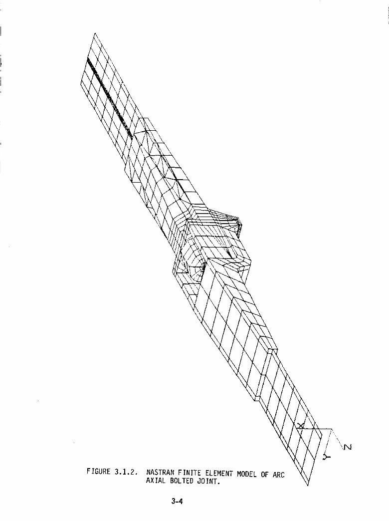
/
FIGURE 3.1.2. NASTRAN FINITE ELEMENT MODEL OF ARCAXIAL BOLTED JOINT.
3-4
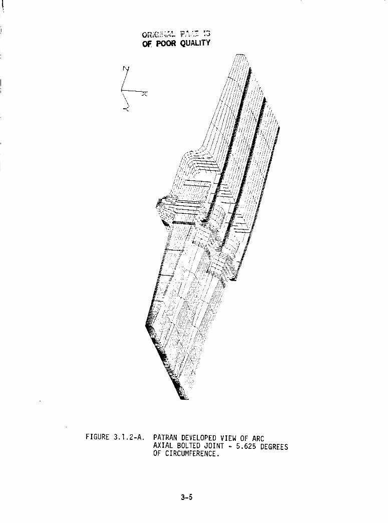
04:. POOR QUALITY
\\
/:
"/;'
:'L;'/ /_
FIGURE 3.1.2-A. PATRAN DEVELOPED VIEW OF ARCAXIAL BOLTED JOINT - 5.625 DEGREESOF CIRCUMFERENCE.
3-5
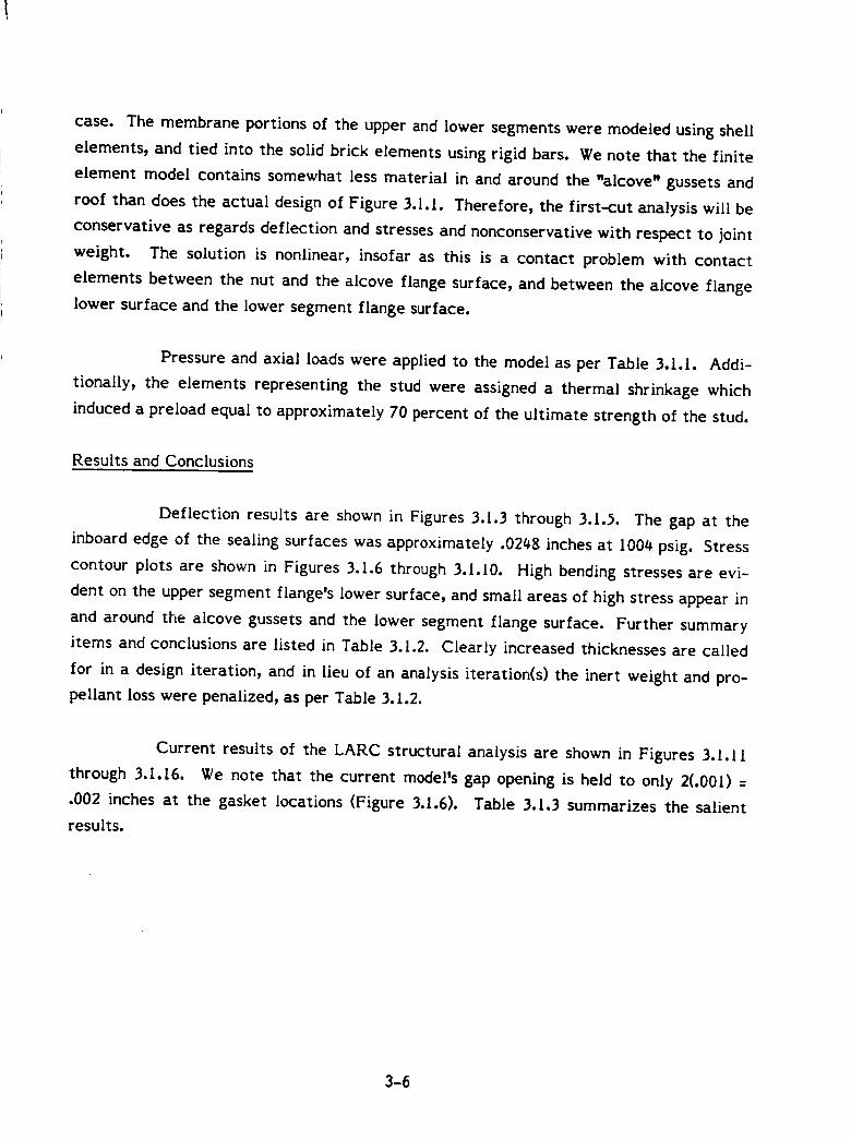
case. The membrane portions of the upper and lower segments were modeled using shell
elements, and tied into the solid brick elements using rigid bars. We note that the finite
element model contains somewhat less material in and around the "alcove" gussets and
roof than does the actual design of Figure 3.1.1. Therefore, the first-cut analysis will be
conservative as regards deflection and stresses and nonconservative with respect to joint
weight. The solution is nonlinear, insofar as this is a contact problem with contact
elements between the nut and the alcove flange surface, and between the alcove flange
lower surface and the lower segment flange surface.
Pressure and axial loads were applied to the model as per Table 3.1.1. Addi-
tionally, the elements representing the stud were assigned a thermal shrinkage which
induced a preload equal to approximately 70 percent of the ultimate strength of the stud.
Results and Conclusions
Deflection results are shown in Figures 3.I.3 through 3.I._. The gap at the
inboard edge of the sealing surfaces was approximately .0248 inches at 1004 psig. Stress
contour plots are shown in Figures 3.1.6 through 3.1.10. High bending stresses are evi-
dent on the upper segment flange's lower surface, and small areas of high stress appear in
and around the alcove gussets and the iower segment flange surface. Further summary
items and conclusions are listed in Table 3.1.2. Clearly increased thicknesses are called
for in a design iteration, and in lieu of an analysis iteration(s) the inert weight and pro-
pellant loss were penalized, as per Table 3.1.2.
Current results of the LARC structural analysis are shown in Figures 3.1.11
through 3.1.16. We note that the current model's gap opening is held to only 2(.001) =
.002 inches at the gasket locations (Figure 3.1.6). Table 3.1.3 summarizes the salient
results.
3-6
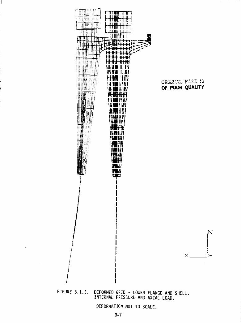
iI
!!
i ii:_iil ::_:ii! i rllilllll Illll I
ii!i,-=,i,_i-'-'-_i_ _ I1_1111III II I•_'_.'..':."___ _ II ,_llIII, Ii!iii_i!'-'-'-'__: I".,Ira Ill. I',' !!ii_i}:_ _:_!i - IIIlilll ill II__ LJ_J_ ]_LJ
,,. ,,_, ,I l_.444-_,_-,'e_m II_Ue Ill BII 4r__.' :'', l':;" _I _"_I_ H_ a_L_il-
...........iii'" ;-'i-"i,. li;|l| _lllilIII |1|_1Ill III III
II IIIII II ! I} I|ilili IIIAll _ ,._;._-..? _'"
IIIIII Ill_l| OF POOR QUALITY
IIIII lll_ll_l MIIIIIIll
I_11111_11I_IIIIIIII
I1_111111111IIilllll
llllltll_Iil
IlIlll
IIIIIIIIIIIIII _.<IIIII
FIGURE 3.1.3. DEFORMED GRID -LOWER FLANGE AND SHELL.
INTERNAL PRESSURE AND AXIAL LOAD.
DEFORMATION NOT TO SCALE.
3-7
r-.:'
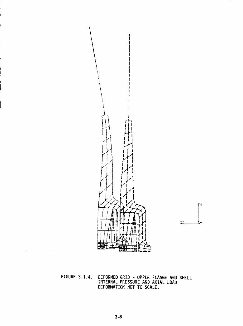
I
IIIIIIIIIIIIIIIIIII
' Ill
!l t!-!i f .4
pr !i]r'i ,,rl
I I._
P'i , I,t_
T r.I-1"/'t tl.
_.'"I I I • /,i-" I 4 1_4"i I.,-",;., _," II .Jk'..." .k--.| I Ilk
i . i . IIi -_-_,y ,I, l / _I,lUll I I,v I
_ !Jlllill-'i ' Illll.r ii / _,dt// II1| I! ,4
i li!!ltilt_'"t÷÷_¢ I
__ _ _ '_-,._---, --- : ......... t_" -t--.._
H_.. ..... I .L L..,&_ .. *
FIGURE 3.1.4. DEFORMED GRID - UPPER FLANGE AND SHELLINTERNAL PRESSURE AND AXIAL LOADDEFORMATION NOT TO SCALE.
3-8
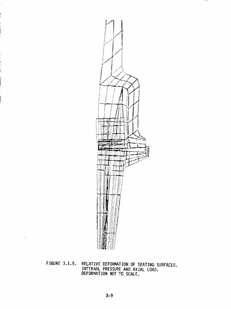
FIGURE 3.1.5. RELATIVE DEFORMATION OF SEATING SURFACES.
INTERNAL PRESSURE AND AXIAL LOAD.
DEFORMATION NOT TO SCALE.
3-9
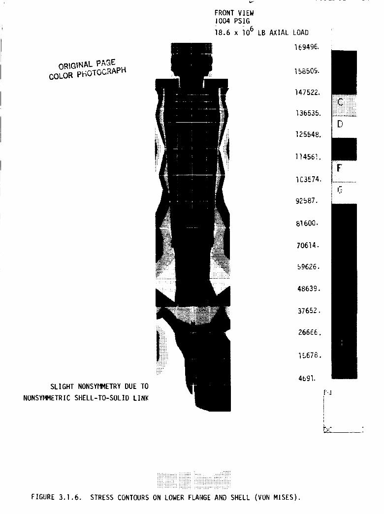
ORIGINALpAGECOLOR pF_OTOGRAPH
SLIGHT NONSYRMETRY DUE TO
NONSYMMETRIC SHELL-TO-SOLID LINK
FRONT VIEW
1004 PSIG
18.6 x -lO6 LB AXIAL LOAD
169496.
158509.
147522.
136535.
125548.
114561.
IC3574.
92587.
61600.
70614.
59626.
48639.
37652.
266£6.
15678.
4691.
::;hiM,:::::::::
iiilitili!!iiii
C..*
f'.,_
! J'°
; I.:
FIGURE 3.1.6.
:iiiiiii_iiiiiiiiiii_ii..........ii::iT::t.':CTz??::t:z ?CTt?:C: TCTTT::Z:Z:IC::'_ZC:Z:::L
?iiii_ii?::i ii_ii!ii )iiiii_ii?ii!i?iiii!!i!i
STRESS CONTOURS ON LOWER FLANGE AND SHELL (VON MISES).
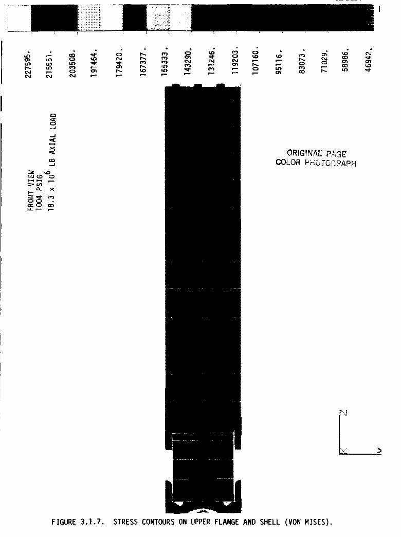
T'" •
w-- O0
O0 _ _
..J
_.J
X
LO(._ 0
CL X
O0
IJ-- _ r'--
ORIGINAE PA_E
COLOR PF_OTC,]2APH
_..., ,
FIGURE 3.1.7. STRESS CONTOURS ON UPPER FLANGE AND SHELL (VON MISES).
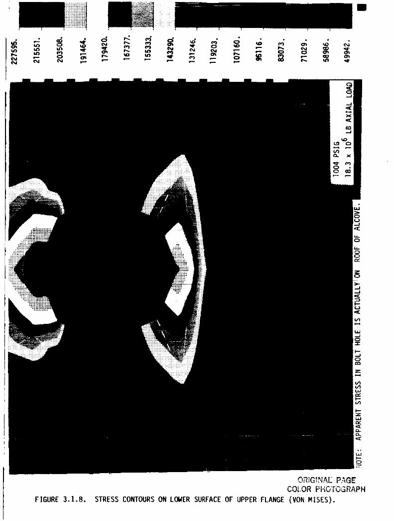
o_O
0
0f_d0
_ro_
I
0
._1
FIGURE 3. ].8.
ORIGINAL PA(_E
COLOR PHOTOGRAPH
STRESS CONTOURS ON LOWER SURFACE OF UPPER FLANGE (VON MISES).
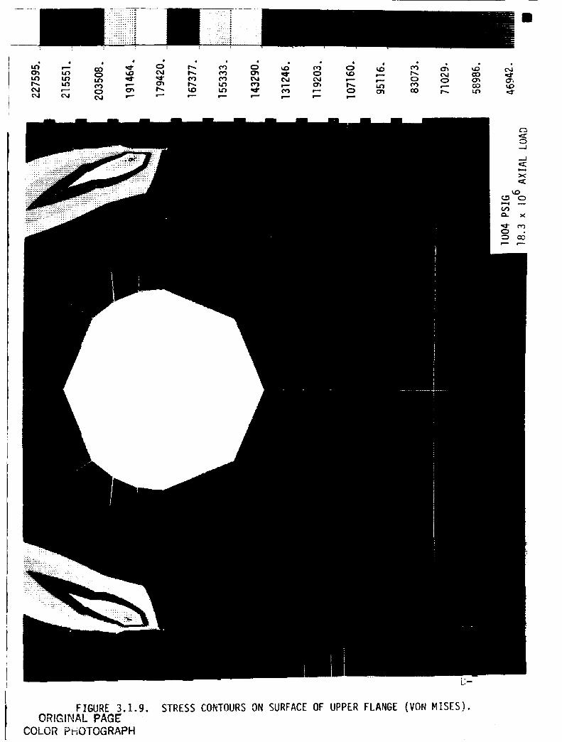
I..(1 l.n I.N _
k'M ,--- Q (:_ I',,.C_l (M N m.-- ,--"
II
FIGURE 3.1.9.ORIGINAl PAGE
COLOR PHOTOGRAPH
STRESS CONTOURS ON SURFACE OF UPPER FLANGE (VON MISES).
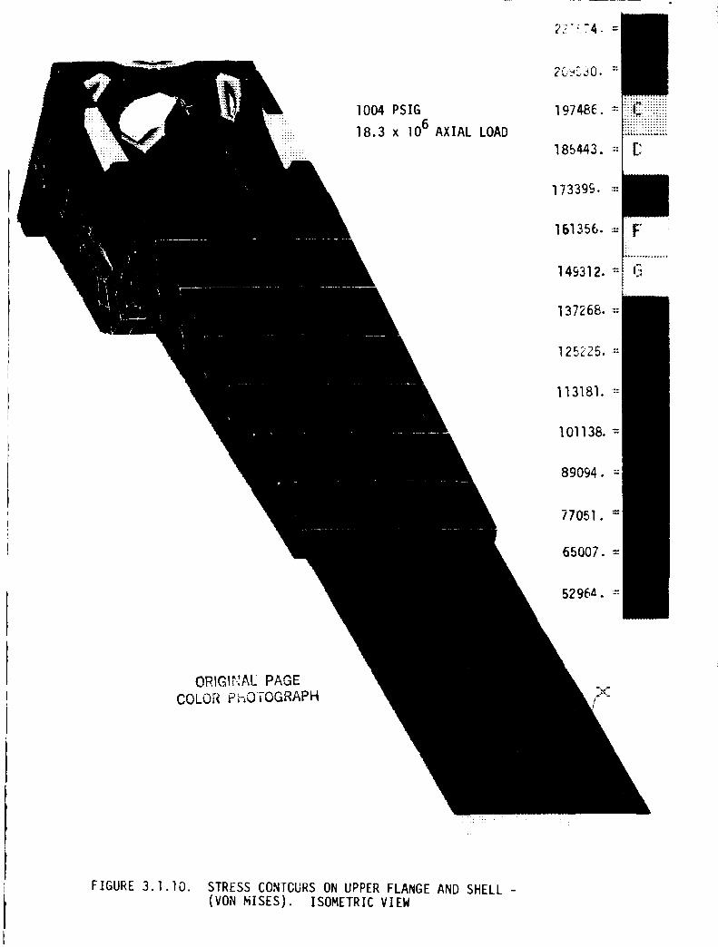
2_'! 74. =
!iii
I004 PSIG
18.3 x I06 AXIAL LOAD
_:{4Z!ii!11ii
173399. =
......... +
149312. =
137268. =
113181. '::
I01138. =:
89094.
77051. =
65007. =
5296_.
ORIGII"_AC PAGE
COLOR PHOTOGRAPH-_.,-
#_,, -
FIGURE 3.1.lO. STRESS CONTCURS ON UPPER FLANGE AND SHELL -
(VON MISES). ISOMETRIC VIEW
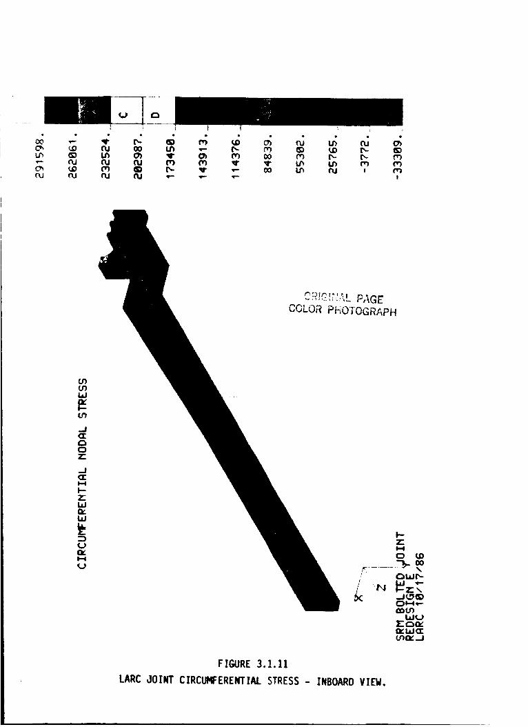
0303
O3
....I
I::)7"
I-4
I-.-7"I.i.I
i,i
1'-4
(_9
FIGURE 3.I.II
LARC JOINT CIRCUMFERENTIAL STRESS - INBOARD VIEW.
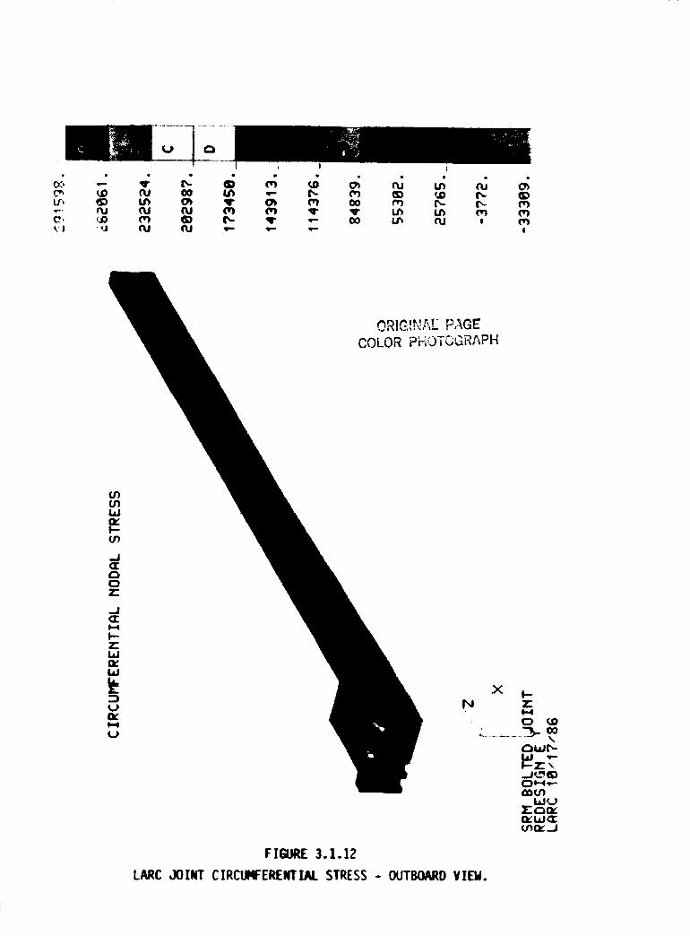
FIGURE 3.1.12
LARC JOIk'T CIRCLIqFERENTIAL STRESS - OUTBOARD VIEM.
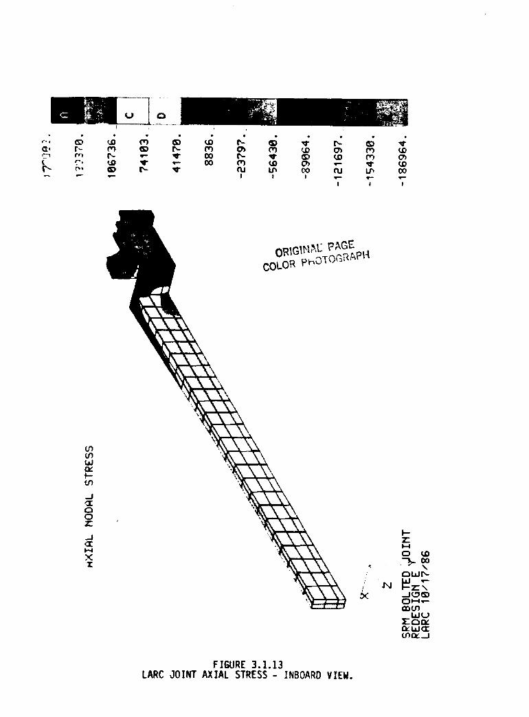
Lr_
wrib,
J
oo
g_t
X
FIGURE 3.1.13LARC JOINT AXIAL STRESS - INBOARD VIEW.
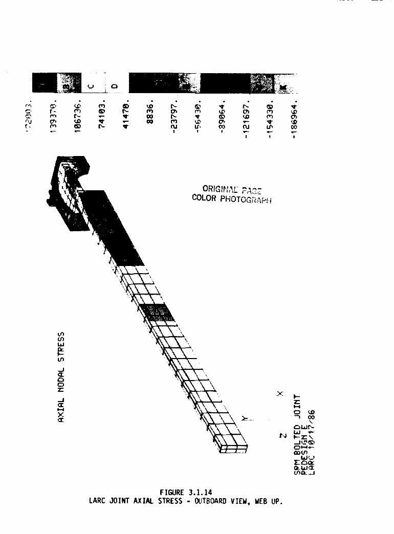
,4 c:, `6 _; _ ,6 rc
t- _ _) r,- sr oo
m _ cs_ (',3 ,.o_ _D rn c_
IS, ¢o r_j t_ oo
! ! !
7-I,--I
"3 (X)\
N I--7"',.
(3e-4.--
u'_J
FIGURE 3.1.14
LARC JOINT AXIAL STRESS - OUTBOARD VIEW, WEB UP.
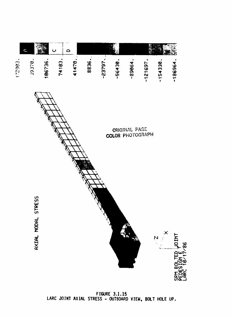
t'J
_)
n_Ch
ORIGINAL FAGE
COLOR PHOTOGRAPH
\
X I--
, , 7"
\t"", I.LIL",-
(_) I,..-0.,e-...ab (.t')
i,,L.I_.,_1c- ,,-,,n,-I;_::I.LI (_1:(.Jr30r.:_J
FIGURE 3.1.15
LARC JOINT AXIAL STRESS - OUTBOARD VIEW, BOLT HOLE UP.
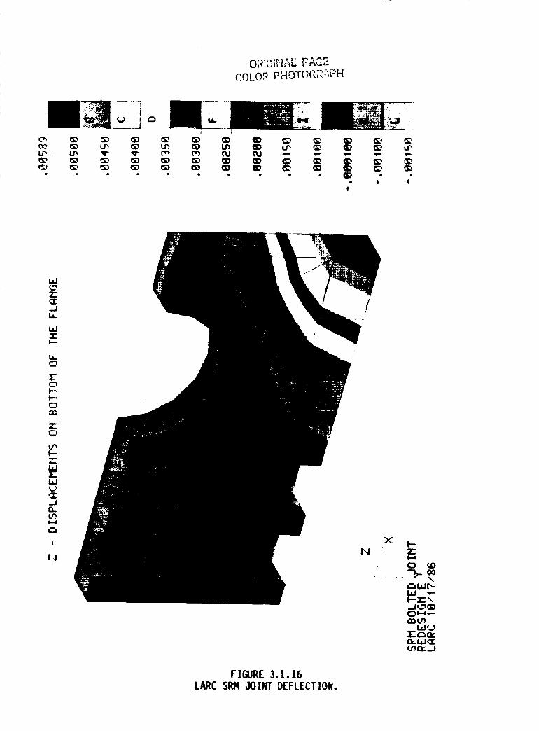
COLOR PHOTOC_"_H
0¢,
m
If'.T
II '_
_--A L.
J i
• I II
Cmll
_J
I.--
0l--I-.
0
_Jnt.nI--4
!
[,I
/
F IGURE 3.1.16LARC SI_I JOINT DEFLECTION•
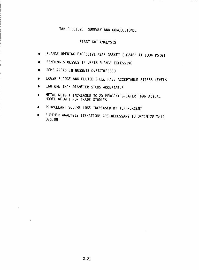
TABLE 3.1.2. SUMMARY AND CONCLUSIONS.
FIRST CUT ANALYSIS
FLANGE OPENING EXCESSIVE NEAR GASKET (.0248" AT 1004 PSIG)
BENDING STRESSES IN UPPER FLANGE EXCESSIVE
SOME AREAS IN GUSSETS OVERSTRESSED
LOWER FLANGE AND FLUTED SHELL HAVE ACCEPTABLE STRESS LEVELS
160 ONE INCH DIAMETER STUDS ACCEPTABLE
METAL WEIGHT INCREASED TO 20 PERCENT GREATER THAN ACTUAL
MODEL WEIGHT FOR TRADE STUDIES
PROPELLANT VOLUME LOSS INCREASED BY TEN PERCENT
FURTHER ANALYSIS ITERATIONS ARE NECESSARY TO OPTIMIZE THIS
DESIGN
3-21
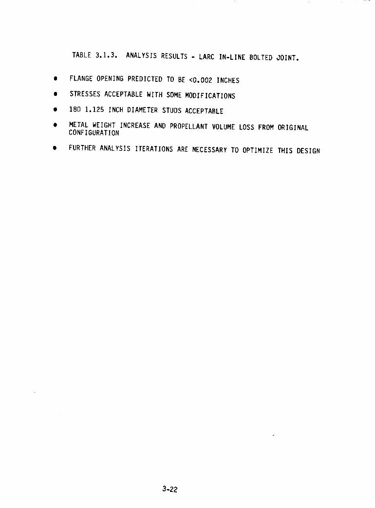
TABLE 3.1.3. ANALYSIS RESULTS - LARC IN-LINE BOLTED JOINT.
0 FLANGE OPENING PREDICTED TO BE <0.002 INCHES
STRESSES ACCEPTABLE WITH SOME MODIFICATIONS
180 1.125 INCH DIAMETER STUDS ACCEPTABLE
METAL WEIGHT INCREASE AND PROPELLANT VOLUME LOSS FROM ORIGINAL
CONFIGURATION
FURTHER ANALYSIS ITERATIONS ARE NECESSARY TO OPTIMIZE THIS DESIGN
3-22
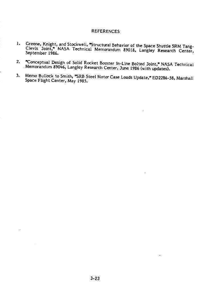
REFERENCES
lo
.
*
Greene, Knight, and Stockwell, "Structural Behavior of the Space Shuttle SRM Tang-Clevis 3oint," NASA Technical Memorandum 89018, Langley Research Center,September 1986.
WConceptual Design of Solid Rocket Booster In-Line Bolted 3oint, w NASA TechnicalMemorandum 89046, Langley Research Center, _Iune L986 (with updates).
Memo Bullock to Smith, "SRB Steel Motor Case Loads Update," ED2286-_8, MarshallSpace Flight Center, May 1985.
3-23
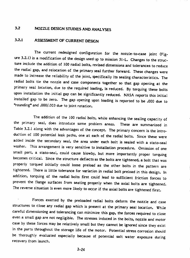
3.2 NOZZLE DESIGN STUDIES AND AN,a_LYSES
3.2.1 ASSESSMENT OF CURRENT DESIGN
The current redesigned configuration for the nozzle-to-case joint (Fig-
ure 3.2.1) is a modification of the design used up to mission 51-L. Changes to the struc-
ture include the addition of I00 radial bolts, revised dimensions and tolerances to reduce
the radial gap, and relocation of the primary seal further forward. These changes were
made to increase the reliability of the joint, specifically its sealing characteristics. The
radial bolts tie the nozzle and case components together so that gap opening at the
primary seal location, due to the required loading, is reduced. By torquing these bolts
upon installation the initial gap can be significantly reduced. NASA reports this initial
installed gap to be zero. The gap opening upon loading is reported to be .000 due to
"rounding" and .000/.003 due to joint rotation.
The addition of the 100 radial bolts, while enhancing the sealing capacity of
the primary seal, does introduce some problem areas. These are summarized in
Table 3.2.1 along with the advantages of the concept. The primary concern is the intro-
duction of 100 potential leak paths, one at each of the radial bolts. Since these were
added inside the secondary seal, the area under each bolt is sealed with a stato-seat
washer. This arrangement is very sensitive to installation procedure. Omission of one
small part, a stato-seal, could cause blowby, but more importantly proper torquing
becomes critical. Since the structure deflects as the bolts are tightened, a bolt that was
properly torqued initially could loose preload as the other bolts in the pattern are
tightened. There is little tolerance for variation in radial bolt preload in this design. In
addition, torquing of the radial bolts first could lead to sufficient friction forces to
prevent the flange surfaces from seating properly when the axial bolts are tightened.
The reverse situation is even more likely to occur if the axial bolts are tightened first.
Forces exerted by the preloaded radial bolts deform the nozzle and case
structures to close any radial gap which is present at the primary seal location. While
careful dimensioning and tolerancing can minimize this gap, the forces required to close
even a small gap are not negligible. The stresses induced in the bolts, nozzle and motor
case by these forces may be relatively small but they cannot be ignored since they exist
in the parts throughout the storage life of the motor. Potential stress corrosion should
be thoroughly evaluated especially because of potential salt water exposure during
recovery from launch.
3-24
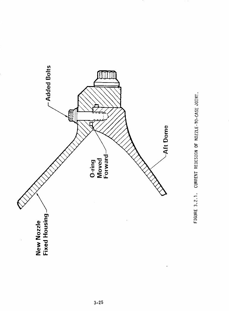
II
Z
CD
I,i
!CDI--
I
NNCD
I.I-
Z
i,i
1,1rY
I--
i,i
r_
NN 00
Z-'e
_ Xem
Zu_
_J
e_
3-25
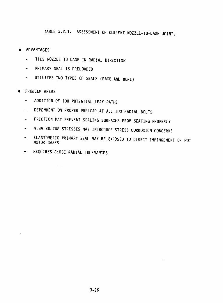
TABLE 3.2.1. ASSESSMENT OF CURRENT NOZZLE-TO-CASE JOINT.
ADVANTAGES
- TIES NOZZLE TO CASE IN RADIAL DIRECTION
- PRIMARY SEAL IS PRELOADED
- UTILIZES TWO TYPES OF SEALS (FACE AND BORE)
PROBLEM AREAS
- ADDITION OF 100 POTENTIAL LEAK PATHS
- DEPENDENT ON PROPER PRELOAD AT ALL 100 RADIAL BOLTS
- FRICTION MAY PREVENT SEALING SURFACES FROM SEATING PROPERLY
- HIGH BOLTUP STRESSES MAY INTRODUCE STRESS CORROSION CONCERNS
- ELASTOMERIC PRIMARY SEAL MAY BE EXPOSED TO DIRECT IMPINGEMENT OF HOT
MOTOR GASES
- REQUIRES CLOSE RADIAL TOLERANCES
3-26
Materials other than elastomerics should be considered for the seals. If the
unvented bonded insulation joint were to fail and allow motor gases to directly impinge
on the seals, a more heat resistant material is desirable.
An assessment of the nozzle-to-case insulation joint is included in Sec-
tion 3._.3.
The current redesigned configuration includes changes for the nozzle liner in
the inlet and throat regions. In addition to material restrictions and processing changes
previously incorporated, revisions to the carbon/phenolic liner ply wrap angles for the
forward nose ring, the aft inlet ring and the throat ring are being introduced. This is
being done to reduce the probability of pocketing erosion such as occurred in STS-SA.
Several of the tests and analyses conducted to investigate this problem support this
change. However, tests and analyses have also indicated that a different material, such
as PAN-based graphite phenolic might have higher resistance to pocketing erosion. It is
recommended that a backup material be developed in case the process sensitive current
material again develops problems.
Specific data concerning other nozzle design changes and the associated
problems has not been obtained and therefore no assessment can be provided.
3.2.2 NOZZLE SUBASSEMBLY 3OINT SEALS
There are five joints in the nozzle subassembly. These joints are currently
sealed with a single o-ring seal with no provision for leak check. These joints are neces-
sary to join the large subcomponents of the nozzle into a single assembly. Some consid-
erations that must be evaluated are; the ease of joint assembly and disassembly, the
incorporation of a redundant seal, the ability to leak check the joint after assembly, and
the temperature sensitivity effects of the seal material in its intended configuration.
The five joints have been studied individually for the above stated considera-
tions. The joint locations are shown in Figure 3.2.2 and are numbered from one to five
for identification purposes. The current joint seal designs are shown in Figure 3.2.3.
3oint I joins the aft section of the nozzle exit cone to the main section of the nozzle exit
cone. It currently utilizes a face seal to prevent gas leakage from passing through the
nozzle joint. 3oint 2 joins the flex bearing assembly to the nose section of the nozzle
3-27
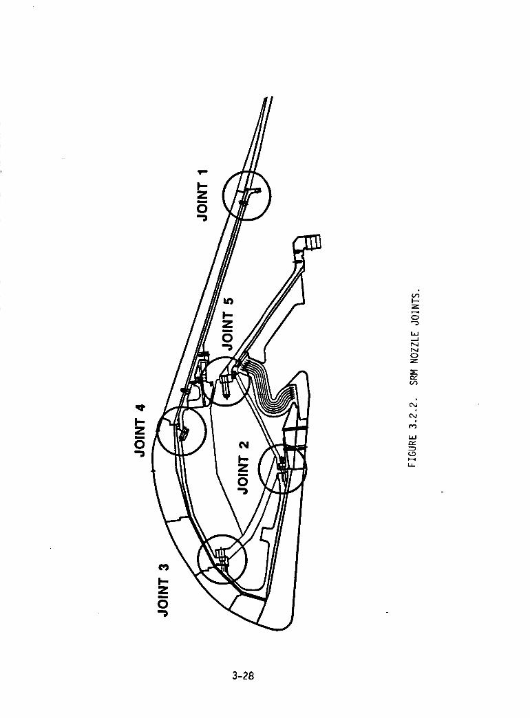
I-.Zi
O,-j
,,4I---Z
O"D
.--I
N1",4OZ
,'w(.,'3
¢,4
,.4
t..,-
3-28
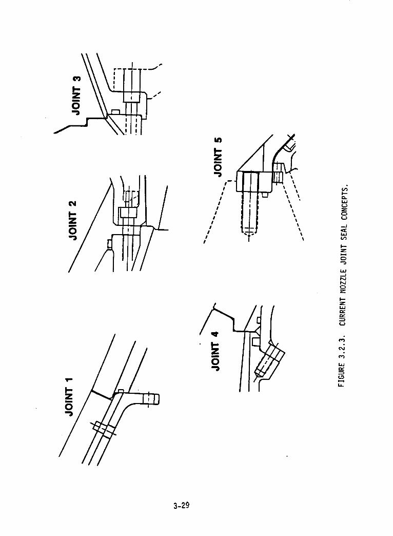
I-
0 •
, III I
II
II
I
I
II
I
,.g
z
L_
zl,i
J
1,1tY
I.
3-29
assembly. Unlike joint l, joint 2 must withstand full motor operating pressure as well as
being exposed to high velocity recirculation. The major purpose for this seal is to pre-
vent gas flow in the structural members making up the nozzle nose shell and flexible
bearing assembly. This joint is exposed to a high differential pressure that will cause
damaging erosion. Joint 3 connects the nose piece with the nozzle throat section and is
similar to joint 2 in operation. The joint 4 o-ring prevents gas leakage in the lower
pressure exit cone region. Two seals are employed: one to prevent gas leakage into the
flexible bearing area, and one to prevent leakage behind the exit cone insulation assem-
bly. Joint _ houses the mechanical interface between the flexible bearing and the nozzle
support structure. It must withstand the loads imported by the flexible bearing torque
while maintaining an adequate seal.
All joints were evaluated for seal design integrity using the following guide-
lines: Each seal must have redundancy, each seal must be verifiable with an external
pressure check, and each joint and seal must be compatible with the assembly procedures
over a defined temperature range. All joints resulted in three different sealing configu-
rations. These seal configurations are shown in a representation by joint 3 in Fig-
ure 3.2.4. The first version consisted of two face seals and a pipe plug port located
between two grooves for seal verification. The second option considered two types of
seals: one face sea! and one gland sea!. The third concept incorporated a face seal and a
gasketing material upstream of the primary o-ring seal.
The two face seals provide redundancy in number, but may not offer the
intent of a redundant seal. If the operational failure of one of the seals occurs, then the
probability of the redundant seal failing is also likely. A face seal in combination with a
gland seal provides the high pressure advantage of a face seal with the assembly advan-
tage of a gland seal. The two seal types operated differently and offer different sealing
features. The face seal lowers the probability of o-ring extrusion due to control of
mating port gaps. The gland seal can provide environmental protection for the face seal
while acting as a backup for the face seal. The combination face seal and gasket utilizes
the above mentioned face seal benefits with the gap filling feature of gasketing mate-
rials. The gasketing material could be a sacrificial insulation or an adhesive material
that would comply with surface gaps and irregularities.
The selected joint/seal configuration is the face seal/gland seal combina-
tion. This combination best utilizes two seal types that have a demonstrated usage in
3-30
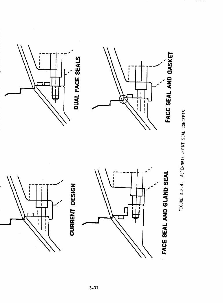
._js
\
pl.I,M
s_
I--
_J
Z0
--/
Z
0
I---
3-31
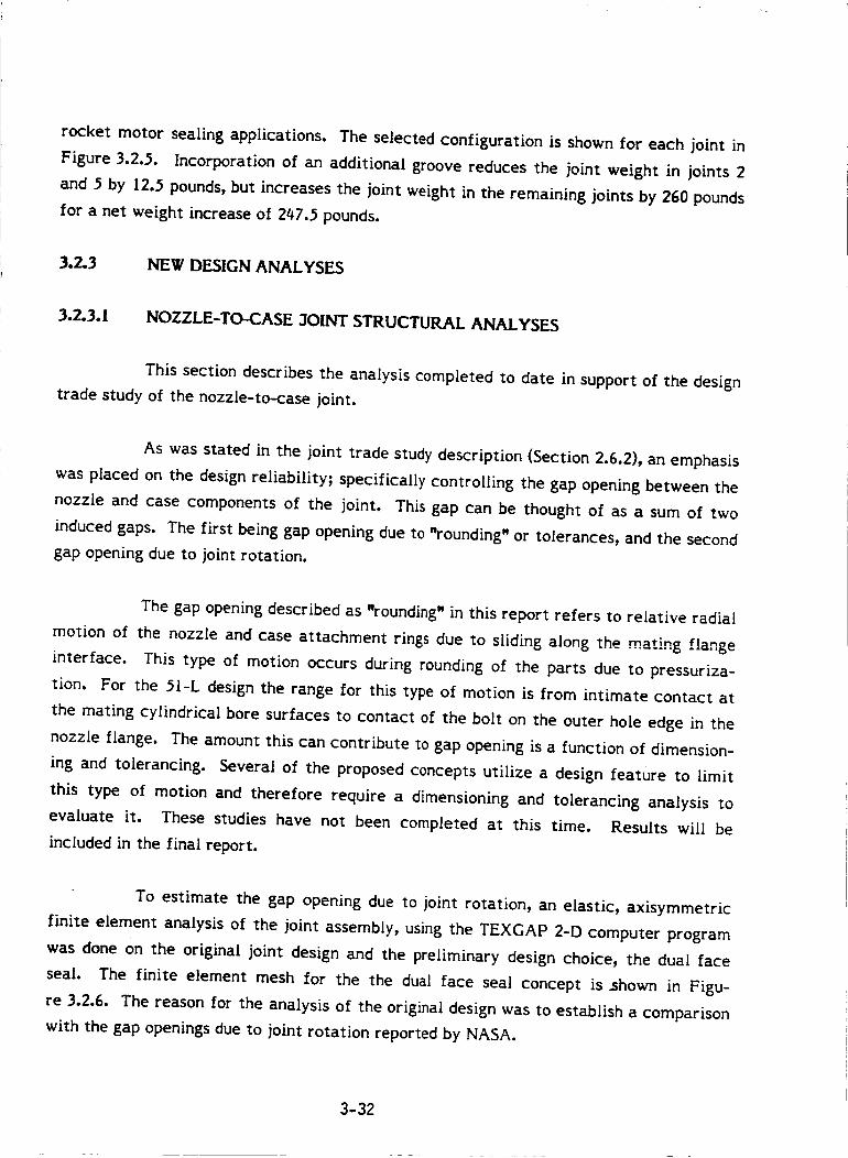
rocket motor sealing applications. The selected configuration is shown for each joint in
Figure 3.2.5. Incorporation of an additional groove reduces the joint weight in joints 2
and 5 by 12.5 pounds, but increases the joint weight in the remaining joints by 260 pounds
for a net weight increase of 247._ pounds.
3.2.3 NEW DESIGN ANALYSES
3.2.3.1 NOZZLE-TO-CASE 3OINT STRUCTURAL ANALYSES
This section describes the analysis completed to date in support of the design
trade study of the nozzle-to-case joint.
As was stated in the joint trade study description (Section 2.6,2)9 an emphasis
was placed on the design reliability; specifically controlling the gap opening between the
nozzle and case components of the joint. This gap can be thought of as a sum of two
induced gaps. The first being gap opening due to "rounding" or tolerances, and the second
gap opening due to joint rotation.
The gap opening described as "rounding" in this report refers to relative radial
motion of the nozzle and case attachment rings due to sliding along the mating flange
interface. This type of motion occurs during rounding of the parts due to pressuriza-
tion. For the 51-L design the range for this type of motion is from intimate contact at
the mating cylindrical bore surfaces to contact of the bolt on the outer hole edge in the
nozzle flange. The amount this can contribute to gap opening is a function of dimension-
ing and tolerancing. Several of the proposed concepts utilize a design feature to limit
this type of motion and therefore require a dimensioning and tolerancing analysis to
evaluate it. These studies have not been completed at this time. Results will be
included in the final report.
To estimate the gap opening due to joint rotation, an elastic, axisymmetric
finite element analysis of the joint assembly, using the TEXGAP 2-D computer program
was done on the original joint design and the preliminary design choice, the dual face
seal. The finite element mesh for the the dual face seal concept is _hown in Figu-
re 3.2.6. The reason for the analysis of the original design was to establish a comparison
with the gap openings due to joint rotation reported by NASA.
3-32
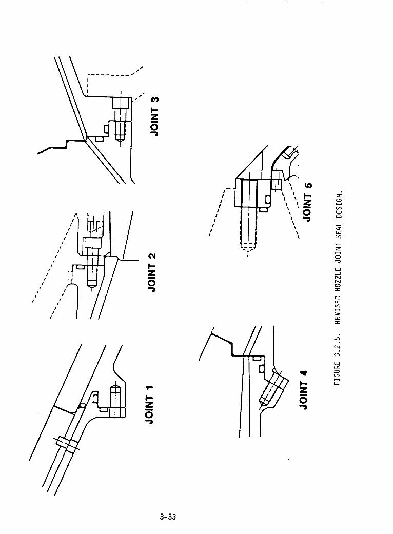
I/
/I
iiiiIII1__
I II1! _
It
J il /
I,-Zm
0
Z
0
!,-Zm
0
II I
I
I
I
E0
/
I--Z
-./NNOZ
L,I-I
t'M
i,i
i,
3-33
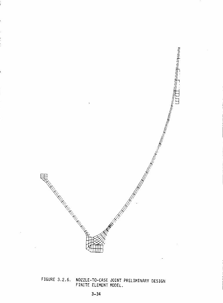
i
i.,,I
I I
I
2
FIGURE 3.2.6. NOZZLE-TO-CASE JOINT PRELIMINARY DESIGNFINITE ELEMENT MODEL.
3-34
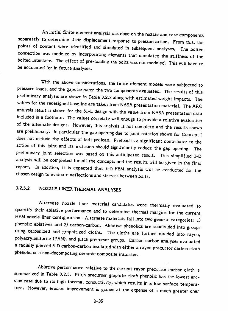
An initial finite element analysis was done on the nozzle and case components
separately to determine their displacement response to pressurization. From this, the
points of contact were identified and simulated in subsequent analyses. The bolted
connection was modeled by incorporating elements that simulated the stiffness of the
bolted interface. The effect of pre-loading the bolts was not modeled. This will have to
be accounted for in future analyses.
With the above considerations, the finite element models were subjected to
pressure loads, and the gaps between the two components evaluated. The results of this
preliminary analysis are shown in Table 3.2.2 along with estimated weight impacts. The
values for the redesigned baseline are taken from NASA presentation material. The ARC
analysis result is shown for the 5I-L design with the value from NASA presentation data
included in a footnote. The values correlate well enough to provide a relative evaluation
of the alternate designs. However, this analysis is not complete and the results shown
are preliminary, In particular the gap opening due to joint rotation shown for Concept I
does not include the effects of bolt preload. Preload is a significant contributor to the
action oI this joint and its inclusion should significantly reduce the gap opening. The
preliminary joint selection was based on this anticipated result. This simplified 2-D
analysis will be completed for all the concepts and the results will be given in the final
report. In addition, it is expected that 3-D FEM analysis will be conducted for the
chosen design to evaluate deflections and stresses between bolts.
3.2.3.2 NOZZLE LINER THERMAL ANALYSES
Alternate nozzle liner material candidates were thermally evaluated to
quantify their ablative performance and to determine thermal margins for the current
HPM nozzle liner configuration. Alternate materials fall into two generic categories: l)
phenolic ablatives and 2) carbon-carbon. Ablative phenolics are subdivided into groups
using carbonized and graphitized cloths. The cloths are further divided into rayon,
polyacrylonitorile (PAN), and pitch precursor groups. Carbon-carbon analyses evaluated
a radially pierced 3-D carbon-carbon insulated with either a rayon precursor carbon cloth
phenolic or a non-decomposing ceramic composite insulator.
Ablative performance relative to the current rayon precursor carbon cloth is
summarized in Table 3.2.3. Pitch precursor graphite cloth phenolic has the lowest ero-
sion rate due to its high thermal conductivity, which results in a low surface tempera-
ture. However, erosion improvement is gained at the expense of a much greater char
3-35
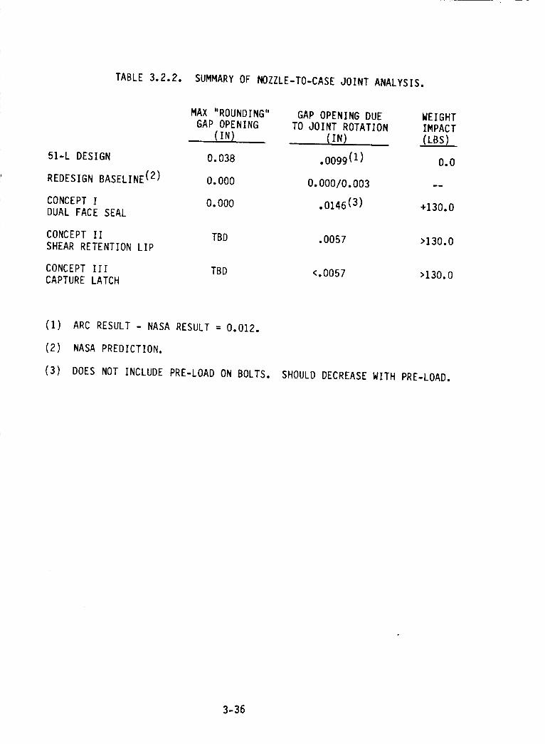
TABLE 3.2.2. SUMMARY OF NOZZLE-TO-CASE JOINT ANALYSIS.
51-L DESIGN 0.038
REDESIGN BASELINE (2) 0.000
CONCEPT I 0.000
DUAL FACE SEAL
CONCEPT II TBD
SHEAR RETENTION LIP
CONCEPT Ill TBD
CAPTURE LATCH
MAX "ROUNDING" GAP OPENING DUE WEIGHT
GAP OPENING TO JOINT ROTATION IMPACT
(IN) (IN) (LBS)
.0099 (1) 0.0
0.00010.003 --
.0146 (3) +130.0
.0057 >130.0
<.0057 >130.0
(i) ARC RESULT - NASA RESULT = 0.012.
(2) NASA PREDICTION.
(3) DOES NOT INCLUDE PRE-LOAD ON BOLTS. SHOULD DECREASE WITH PRE-LOAD.
3-36
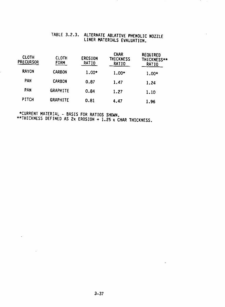
TABLE3.2.3. ALTERNATE ABLATIVE PHENOLIC NOZZLE
LINER KATERIALS EVALUATION.
CHAR REQUIREDCLOTH CLOTH EROSION THICKNESS THICKNESS**
PRECURSOR FORM RATIO RATIO RATIO
RAYON CARBON 1.00" 1.00" 1.00"
PAN CARBON 0.87 1.47 1.24
PAN GRAPHITE 0.84 1.27 1.10
PITCH GRAPHITE 0.81 4.47 1.96
*CURRENT MATERIAL - BASIS FOR RATIOS SHOWN.
**THICKNESS DEFINED AS 2x EROSION + 1.25 x CHAR THICKNESS.
3-37
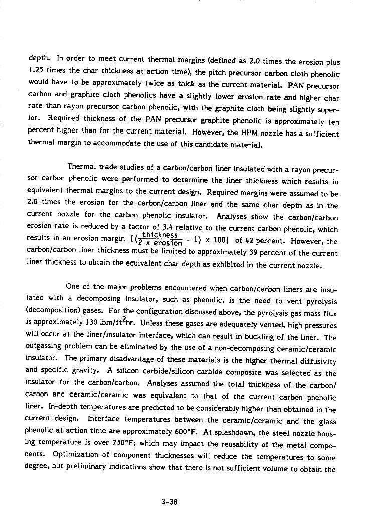
depth. In order to meet current thermal margins (defined as 2.0 times the erosion plus
1.25 times the char thickness at action time), the pitch precursor carbon cloth phenolic
would have to be approximately twice as thick as the current material. PAN precursor
carbon and graphite cloth phenolics have a slightly lower erosion rate and higher char
rate than rayon precursor carbon phenolic, with the graphite cloth being slightly super-
ior. Required thickness of the PAN precursor graphite phenolic is approximately ten
percent higher than for the current material. However, the HPM nozzle has a sufficient
thermal margin to accommodate the use of this candidate material.
Thermal trade studies of a carbon/carbon liner insulated with a rayon precur-
sor carbon phenolic were performed to determine the liner thickness which results in
equivalent thermal margins to the current design. Required margins were assumed to be
2.0 times the erosion for the carbon/carbon liner and the same char depth as in the
current nozzle for the carbon phenolic insulator. Analyses show the carbon/carbon
erosion rate is reduced by a factor of 3._ relative to the current carbon phenolic, whicht[ thickness
results in an erosion margin t _2" _ er_n - 1) x 100] of 42 percent. However, the
carbon/carbon liner thickness must be limited to approximately 39 percent of the current
liner thickness to obtain the equivalent char depth as exhibited in the current nozzle.
One of the major problems encountered when carbon/carbon liners are insu-
lated with a decomposing insulator, such as phenolic, is the need to vent pyrolysis
(decomposition) gases. For the configuration discussed above, the pyrolysis gas mass flux
is approximately 130 lbm/ft2hr. Unless these gases are adequately vented, high pressures
will occur at the liner/insulator interface, which can result in buckling of the liner. The
outgassing problem can be eliminated by the use of a non-decomposing ceramic/ceramic
insulator. The primary disadvantage of these materials is the higher thermal diffusivity
and specific gravity. A silicon carbide/silicon carbide composite was selected as the
insulator for the carbon/carbon. Analyses assumed the total thickness of the carbon/
carbon and ceramic�ceramic was equivalent to that of the current carbon phenolic
liner. In-depth temperatures are predicted to be considerably higher than obtained in the
current design. Interface temperatures between the ceramic/ceramic and the glass
phenolic at action time are approximately 600°F. At splashdown, the steel nozzle hous-
ing temperature is over 750°F_ which may impact the reusability of th.e metal compo-
nents. Optimization of component thicknesses will reduce the temperatures to some
degree, but preliminary indications show that there is not sufficient volume to obtain the
3-38
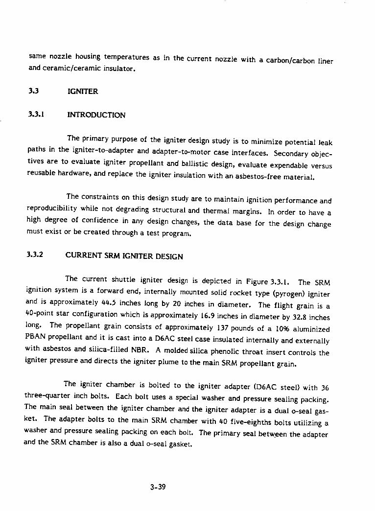
samenozzle housing temperatures as in the current nozzle with a carbon/carbon liner
and ceramic/ceramic insulator.
3.3 IGNITER
3.3.1 INTRODUCTION
The primary purpose of the igniter design study is to minimize potential leak
paths in the igniter-to-adapter and adapter-to-motor case interfaces. Secondary objec-
tives are to evaluate igniter propellant and ballistic design, evaluate expendable versus
reusable hardware, and replace the igniter insulation with an asbestos-free material.
The constraints on this design study are to maintain ignition performance and
reproducibility while not degrading structural and thermal margins. In order to have a
high degree of confidence in any design changes, the data base for the design change
must exist or be created through a test program.
3.3.2 CURRENT SRM IGNITER DESIGN
The current shuttle igniter design is depicted in Figure 3.3.1. The SRM
ignition system is a forward end, internally mounted solid rocket type (pyrogen) igniter
and is approximately 15l$.$ inches long by 20 inches in diameter. The flight grain is a
40-point star configuration which is approximately I6.9 inches in diameter by 32.8 inches
long. The propellant grain consists of approximately 137 pounds of a 1096 aluminized
PBAN propellant and it is cast into a D6AC steel case insulated internally and externally
with asbestos and silica-filled NBR. A molded silica phenolic throat insert controls the
igniter pressure and directs the igniter plume to the main SRM propellant grain,
The igniter chamber is bolted to the igniter adapter (D6AC steel) with 36
three-quarter inch bolts. Each bolt uses a special washer and pressure sealing packing.
The main seal between the igniter chamber and the igniter adapter is a dual o-seal gas-
ket. The adapter bolts to the main SRM chamber with 40 five-eighths bolts utilizing a
washer and pressure sealing packing on each bolt. The primary seal between the adapter
and the SRM chamber is also a dual o-seal gasket.
3-39
i -!i
NI ]l ,.
!_-i!it I1_1111lltilil:lll
I] _ .ft "_,11_:+
OR.'.GIF_ALPAGE ISOF POOR QUALITY
9 ! -"r. " .'Z"; t_l !!
_,¢ o ,,- -
ll--
'il_ ) .
E • _o II
II _ "
_ R_ g
,__1
l.l.JI---
Z
I--Z
LI.I
3-40
The ignition initiator is a small, multinozzled asbestos- and silica-filled NBR
insulated steel cased rocket motor containing 1.4 pounds of propellant in a 30-point star
configuration. The initiator case and the safety and arming (S&A) device attach to the
igniter adapter. The S&A is bolted to the adapter using I0 bolts. A dual o-seal gasket
forms the dual redundant seals with special packing on each bolt as an environmental
seal.
The S&A device consists of a reusable actuating and monitoring (A&M) and an
expendable booster-barrier assembly containing a mixture of BKNO 3 pellets and gran-
ules. Two redundant NASA standard initiators (NSIs) provide positive ignition. The NSIs
utilize dual redundant seals and the A&M uses dual o-ring seals on the barrier rotor shaft.
Totaling up the seals in the igniter/S&A) there are 6 primary seals, 42
secondary seals, and 88 environmental seals. The primary seals are the fundamental
seals that hold igniter or motor gas pressure while secondary seals would seal against gas
pressure only if the primary seals failed. The environmental seals are used for sealing
out the environments except for the bolt seals on the bolts that attach the igniter cham-
ber to the igniter adapter. These seals are secondary seals and environmental seals.
3.3.3 IMPROVED SRM IGNITER SYSTEM
The improved SRM igniter is depicted in Figure 3.3.2. This system is a for-
ward end, internally mounted solid rocket type (pyrogen) igniter. The igniter is approxi-
mately 19 inches in diameter by 34 inches long, overall. The flight grain is a t0-point
star configuration that is 16.4 inches in diameter by 21.6 inches long. The propellant
grain consists of 119 pounds of 18% aluminized HTPB propellant cast into a 200 maraging
steel case with an integral welded igniter adapter and a removable aft closure held in
place using 36 high strength 3/4 inch bolts. The case is insulated internally and exter-
nally with Kevlar and silica-filled Hypalon. A molded silica phenolic throat insert con-
trols the igniter pressure and directs the igniter plume to the main SRM propellant grain.
The igniter adapter is bolted to the main SRM chamber with 40 five-eighths
bolts that have a washer and an environment seal on each bolt, The primary seal consists
of a radially compressed aerospace G-T ring that seals against high pressures with larger
clearances than an o-ring. This design is utilized for dynamic rod and piston seals and
will not twist under installation, The secondary seal is a resilient metal c-ring mounted
3-41
x:,_._,.,_ PAGE IS
OF POOR QUALITY
!
\
I-'-
z
rYC,O
or)
O
O
I.,l_]rY
L.I_
3-42
as a face seal between the adapter and the main SRM chamber. Metal c-ring seals are
very high temperature seals (up to 2000°F) and they are resilient seals that maintain
sealing in the event of flange separation caused by thermal or pressure shock or by bolt
creep. Both types of seals are also much more compression set resistant than o-rings and
have a higher recovery rate than o-rings, allowing them to always maintain contact with
the sealing surfaces as the gap opens.
At the forward end of the igniter, mounted to the igniter adapter is the
ignition initiator. The initiator utilizes the same hardware that is used in the current
design but it is loaded with ARCADENE 360A HTPB propellant to maintain compatibility
with the main igniter propellant. The grain design is also the same as in the current
design since the 360A propellant is tailored to have the same burn rate as the TP1178.
The initiator case will be insulated with Kevlar and silica-filled Hypalon to the same
thickness that the abestos-silica NBR is applied on the current design.
The S&A device will remain the same as that used on the current design with
the asbestos containing parts replaced with non-asbestos materials. The S&A clutch disc
material will be replaced with Kevlar phenolic while the S&A commutator material will
be replaced with ceramic phenolic.
The S&A is attached to the igniter adapter using l0 bolts with a washer and
special packing used as an environmental seal. The S&A is sealed to the adapter using a
radially squeezed G-T ring and a face sealing metal c-ring, the same as in the adapter to
main SRM case. The dual o-ring seals on the A&M main rotor will remain the same as
will the seals on the NSIs. For the external environmental seals, either an o-ring type
seal or a formed in-place gasket material (i.e, RTV) can be used on the igniter adapter
to SRM case and the S&A to igniter adapter.
Total weight savings for the improved versus the production igniter is approx-
imately 1I0 pounds. The reduced grain length (32.8" vs. 21.6") and the thinner insulation
on igniter case account for this weight reduction.
3.3.¢ IGNITER PROPELLANT
The igniter propellant selected for the improved igniter is ARCADENE 360A,
which is detailed in Table 3.3.1. ARCADENE 360A is an 88% solids-loaded HTPB
3-43
TABLE 3.3.1.
INGREDIENT WT
R-45 HT BINDER 10.0
DOA 2.0
A1 POWDER 18.0
Fe203 1.5
AP (60/40 200u/MA) 68.5
I00.0
ARCADENE 360A.
TOTAL SOLIDS
I°sps
DENSITY
EQUILIBRIUM Tc
C*
E
GAMMA
BURNING RATE (1000 PSI) 0.70
PRESSURE EXPONENT 0.48
MECHANICAL PROPERTIES (2 in/min x head)
70°F
88%
260.7 Ibf-sec/Ibm
0.0655 Ib/cu-in
3508°K
5123 ft/sec
10.74
1.166
-40°F
MAX. STRESS (PSI) 201
% STRAIN AT MAX. STRESS 30
TANGENT MODULUS (PSI) 1540
514
43
12,100
+160°F
128
26
1010
3-44
propellant with a bimodal blend of ammonium perchlorate (AP) and 18% aluminum. This
propellant is a variant of the MLRS propellant of which ARC has loaded over 28 million
pounds into MLRS motors. The higher burn rate necessary for the SRM igniter applica-
tion is achieved by increasing the percentage of iron oxide (7% vs. 1.5%) and by varying
the percentage of fine versus course AP in the bimodal blend. This propellant is com-
pletely characterized for use through the MLRS program and represents very low risk in
the SRM igniter application. Prior to casting the propellant, the insulated case will be
barrier coated with EA-946 and then lined with ARL-[51 liner. Both of these materials
have been well characterized for use with this propellant in the MLRS program.
3.3.5 IGNITER GRAIN DESIGN
The igniter grain is shown in Figure 3.3.3 and described in Table 3.3.2. The
grain design is a 40-point star design with the web between star points varying from
0.20 inches at the head end to 0.05 inches at the aft end. The star tip radii are
4.90 inches from the igniter centerline. The maximum nominal mass flow rate is approx-
imately 65 percent of the DM-I igniter firing. The molded cellulose phenolic nozzle has
a throat diameter of 6.60 inches and will have a projected 0.030 inches total erosion on
the diameter during the igniter firing. Maximum expected operating pressure (MEOP,
+30 condition) is projected to be 1660 psia.
This grain design matches very closely the performance from the current
production igniter. Igniter MEOP and mass flow rates compare very favorably with SRM
firings QM-i and QM-2 as shown in Figure 3.3.4. Igniter plume contact with the SRM
will therefore match the current production igniter and ignition times for the SRM should
remain the same.
3.3.6 IGNITER INSULATION
The improved igniter insulation selected for replacing the current asbestos
and silica-filled NBR is Kevlar and silica-filled Hypalon. This selection comes from the
extensive trade studies documented in Section 2.4. Preliminary estimates of insulation
requirements, based upon reported Material Affected Rates (MARs) for the igniter in
QM-2, using a 2.0 MAR safety factor, and reducing the igniter length results in a total
igniter assembly insulation weight reduction of approximately 78 pounds. On the aver-
age, external igniter case insulation is reduced in thickness by 20 percent while the
3-45
- A0
°
/
F°-]|
/
1...---..4
\
/
\/,,,'x I_ ,,,...,
e',e"
L_I--
Z
¢YV3
I,i
0
,,4
,4W
3-46
TABLE 3.3.2. SRM IGNITION SYSTEM.
PROPELLANT
- HTPB/AP/AI
- rlO00 = 0.70 ips @ 60°F
GRAIN CONFIGURATION
119 lb. GRAIN WEIGHT
40-POINT STAR, 21.6 IN. LONG BY 16.4 IN. OD4.90 IN. RADIUS TO STAR TIPS
0.20 IN. TO 0.05 IN. WALL WEB TAPER FORWARD TO AFT
NOZZLE
CELLULOSE PHENOLIC
0.030 IN. TOTAL PREDICTED EROSION ON DIAMETER
6.60 IN. THROAT DIAMETER
PERFORMANCE
- 323 Ibm/s MAXIMUM NOMINAL MASS FLOW RATE
- 1660 PSIA MAXIMUM EXPECTED OPERATING PRESSURE (90°F, +3a CONDITIONS)
3-47
i/
/
.j ! I
VISd ..... d:janSS:_,_
(')
!_
0
00
6
I
i o z
00
00
6
0C)
0
@
0C)
_..)CJ_Z
I---_-
L_O
V'_ Lul
UJc_,-"._j
Z
uJ_-
_'--_ZZ
_.--II=LII*--
I.._Z>CD0_'--_
0.._-"
w
D
3-48
internal case insulation is reduced by 33 percent. The igniter initiator insulation thick-
ness was not changed.
The silica phenolic throat insert will be replaced with a lower cost, higher
performance cellulose phenolic. Estimated cost savings of the cellulose versus the silica
phenolic are approximately 85% for the raw material. The cellulose phenolic is also
predicted to have 80% of the erosion experienced in the silica phenolic and 15% less
weight due to a lower density.
These insulation thicknesses keep the igniter hardware below the required
300°F during SRM action time and t_00°F following SRM web burnout per specification
CPWI-3300.
3.3.7 IGNITER SEALS
The primary objective of this design study is to reduce potential exhaust gas
leak paths from the igniter assembly. To achieve that goal, various hardware configura-
tion concepts were examined to reduce the overall number of primary and secondary gas
seals. In the current production igniter, there are 6 primary, 42 secondary, and 88 envi-
ronmental seals as detailed in Table 3.3.3. In the proposed design, the case and adapter
will be manufactured from 200 maraging steel and welded together, eliminating all case-
to-adapter seals in the production design (Figure 3.3.2). Using this design, the total
number of seals is reduced to S primary, } secondary, and 52 environmental. This pro-
vides a delta of I primary seal and 37 secondary seals. The secondary seals are drasti-
cally reduced due to the elimination of the bolts and the special bolt packing (stato-seals)
in the igniter case to adapter joint.
A trade study was conducted to determine what type or types of primary and
secondary seals to utilize in the improved igniter design. The trade study is presented in
Table 3.3.4. The primary seals selected for use on the igniter adapter to SRM case and
the S&A-to-igniter adapter are aerospace G-T rings. These rings will be radial squeeze
seals and are commonly used to seal hydraulic fluid up to 8000 psi. These seals are very
resistant to extrusion due built-in non-extrusion rings, provide a positive_seal at zero or
low pressures due to radial compression at installation and are not subject to roiling or
spiral failures. These G-T ring seals permit sealing with larger gaps than o-rings under
expansion of a pressure vessel as it is pressurized. Aerospace G-T rings are also designed
3-49
..J
I.¢J(.,'1
.-J
(,'1C_
Z
._J
O--
s....4
Z
Zl
61
L,hJl
_t
OI
IJ=i_fJ'1!
_'='I
n •L='.I
J,
g=_l
_..[C2_iccI
_,,,_,L,Ulml
C[I.i=.l
Q
,k
0
!
_vl z
w
z
I--
,M-
_ w
I--I.d..iI-- Z
r.DZCDi-.=1
,,-II
,..-I I
"i
•"_ i
C)I"-
L,JI"
,'V" L.)I,II--" 3E
Z(3I....=1
CM
t'M
...I
I"
I"
--=1
i,IU'I
..J
I--"Zhi=EZO
I--4
Zt.IJ
Z
ZO(J
{,"1
O'1
ZQI,....II--(JZ
I.I.
.=.1
hi
hi"r"I--"
Lt..C:)
_,O
"W
,.,,,.
ZC:)(..)
I.I.II""V1
...I
.--ICZ:I.tJ
_D
-J(..)Z>..,=4
"1{"It
V1-=1
¢1")
Z
I-"
1.1.1
V1V)I,I,"v"
LI.I
:::)-.J
Z
I--"C:)Z
(/1
hiC:)E_
4"4-
3-50
ur} ,_- um co
oo t_Ju_
co oo
LAJ
1,1
J
LJJ
mm
Z
m_I
_LIJ
_'-_L_J =.Jh-- _..>
_-- LL_
_.0 --J
0
O0
A
OC
L_J
Z
C_
cr_
_JO0
i,iZ_.__Z
O.L_J
P_
l_J
Z
_Ei,i-J
h--
_L_J
Z_-
_-__-_
h--
O0
O0
u_
i,i
Z
h--
X
i,iO_
O0
i,i
Z
m_t_J.--J
}--
i,im_
_Ei,i
ur_
--J
CO
¢C
Z
..J
i,i
_J
O0
Z
ZIJJ _-,_.> -_-_.>
ZZ
°8
QJ
Z
h--
t_J
Z
t_
m_h--XI,i
O_
u_
--J
oO_J
m-
"l-
mm
C_
h--
LIJh_
3-51
to fit any groove defined in specification MIL-G-_I4F. Rubber compounds allow tem-
perature coverage from -70°F to +_0°F.
The secondary seals for the igniter adapter to SRM case and the S&A to
igniter adapter are resilient metal c-rings. These rings will seal up to 9800 psi in a gland
with a 32 RMS finish and can handle temperatures from cryogenic to 2200°F. A metal
c-ring seals at low and no pressure due to compression from the flange joint. System
pressure then supplements the sealing force by forcing the walls of the ring against its
mating surfaces.
Both the G-T ring and metal c-ring seals are more compression set resistant
than standard o-rings due to their basic designs. In dynamic loading situations where the
gap between mating sealing surfaces tends to open, their resiliency assures that they will
maintain contact with the sealing surfaces. By separating the seals into radial and face
seals with different temperature capabilities for each, we are assured that no credible
single event can cause a failure of both the primary and the secondary seal.
The aft closure will be sealed with a single static face seal that is similar in
design to the G-T rings described above. It consists of an "L" shaped elastomeric sealing
element and a mating non-extrusion ring. At low or zero pressure, the static face seal
(SFS) seals like an o-ring. A pressure increase causes the elastomer to seal more tightly
while the non-extrusion ring precludes extrusion. SFSs can seal with clearance gaps up to
0.015 inches and to pressures exceeding 10,O00 psi. A single seal is utilized due to the
fact that any leakage here would be into the SRM main chamber and should not compro-
mise ignition (assuming leakage is not gross).
3.3.8 SUMMARY
The proposed igniter design utilizes a one-piece case/igniter adapter made
from 200 maraging steel that is insulated internally and externally with Kevlar and
silica-filled Hypalon. An aft closure bolts to the case and allows grain casting and man-
drel pulling from the aft end of the igniter. An HTPB propellant, ARCADENE 360A, a
variant on our well characterized MLRS propellant, will be utilized for the propellant
grain. A combination of elastomeric and metal seal rings will be utilized to provide the
minimum number of primary and secondary seals while providing superior sealing under
all operating conditions of the SRMs.
3-52
3.4 INSULATION
3.4.1 CASE INSULATION
In Section 2.0.2 the insulation trade study identified some non-asbestos mate-
rials which were rated better than the current NBR material containing asbestos and
silica. In studying the results of this effort, it became apparent that the top insulation
candidates differed significantly in some of the rating categories with no one candidate
excelling in all categories. In the design studies which have been performed to date, it
became apparent that the ideal insulation system would logically be a combination of
materials used in such a way that advantage could be taken of the best qualities of each.
Table 3.4.1 presents a design trade in which the top candidates and rankings
from Section 2.4.2 have been reproduced and compared to two hybrid insulation sys-
tems. The design philosophy is to allow the low thermal diffusivity of the Hypalon/
Kevlar/silica material to provide the optimum thermal protection next to the reusable
case. A more erosion resistant material would be used near field joints and in areas
which are exposed during propellant burn such as the aft case. As the design trade
presented in Table 3.4.1 and illustrated in Figure 3.4.I shows, the hybrid system using
USR-3800 as the erosion resistant material outscores any of the individual materials.
One of the advantages of the USR-3800 is the proven compatability of the NBR material
with the propellant. The USR-3g00 would also be used as the molded inhibitor material
because of the erosion resistance required in these joint area.
The use of a hybrid system in the design poses no difficulty to the automated
ribbon lay-up process which was described in Section 2.4.1. the second material can be
wound directly onto the first with the resulting hybrid being vulcanized at the same
time. The main concern in such a hybrid system is the quality of the bond which will be
formed when the materials are vulcanized together. Initial tests have been performed at
ARC in which an NBR material was vulcanized to a Hypalon/Kevlar/silica material.
When pulled apart the failure occurred in the NBR rather than at the juncture of the
materials. These data show that the interface is stronger than the materials themselves.
Complete thermal analyses with in-depth insulation sizing have not been
completed. This work is planned for the remainder of the current program. The criteria
for the trade and design studies to date were to select materials with equivalent or
3-53

_3
Z
i,o
Z
Oj..=..q
I'--
,.,_l
Z
LLI
1.1-1
I---
Z
N
N
Z
Z
"T"
• • • • • • • • • • • • • •
,-,=_J
Z
>_
*eoe ee e*e • *e e
.-t'_
e6 ooel oe ee* • • •
"" "-"-" "" _'" 5 ""
! .: 1
z
_r'
x
14
.,=.,
..,I
Z
3-54
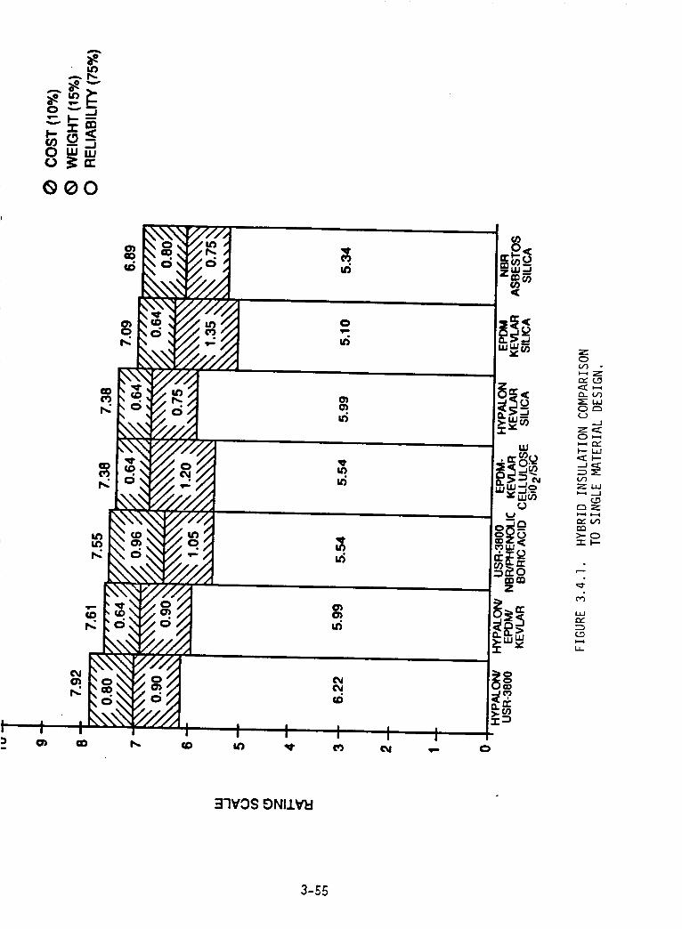
A
_e
8 P,,rr
GO0
I t
I<
i<
=
I
t .....
O.I/i 0
c5:.,.....,
4",:_-',.'_
%.",_,V7
,,,,-,_,,,,_
"//_.,
_ iI!i..
J'ff,f,d
#l,"/.iI
i
!
I
ll')
I I II , I I
I I I I I I
0
Z0i.#')
_-_C__oQ
Or",
.-I
_...__
ZL_I
>-0
_4
tY
:I'IVOS E)NIIVI:I
3-55
better thermal protection and erosion resistance when compared to the current insulation
material. Insulation thicknesses for the Block lI design will not therefore exceed those of
the current HPM design. Because of the density differences (Section 3._._) between the
proposed and current materials, the same volume of insulation (assuming 2095 Hypalon
and 8095 USR-3800) shows a weight saving of 1600 pounds on the current HPM insulation
weight of 18)670 pounds. The insulationsizingwhich willbe performed in the remainder
of this program willdefinitizethe splitbetween the two materials and consequently the
weight savings.
3.#.2 CASE INSULATION JOINTS
Current case insulation field jointshave inadequate reliabilitywhich stems
from two major design flaws. The firstis the use of zinc chromate putty in the gap
between case insulationsegments which provides a good static seal if it isapplied cor-
rectly. However, zinc chromate putty does not have a sufficientsealing capability in a
dynamic environment where case deflectionsare significant. Deflections combined with
internal pressure loads can create flow paths through the putty which cause o-ring ero-
sion if flow rates are sustained or if the o-ring is not seated. Secondly, reliance on
pressure-actuated o-ring seals in conjunction with an unvented insulationjoint increases
the likelihoodof failure. Loss of the insulationseal during motor operation can resultin
local erosion of the o-ring prior to it being properly seated. These problems illustrate
that the selection of the insulationjoint configuration must in part depend on the case
seal design.
The selected case joint seal consists of a metal jacketed gasket and c-ring
which are fixed in a compressive state by the use of bolted flanges. In this design, the
insulation joint does not need to allow for pressure bleeding to actuate sealing. The
insulation joint can be either a vented or unvented configuration. Initial studies evalu-
ated the merits of vented versus unventecl insulation joints. Evaluation criteria and their
relative importance (denoted by weighting factors) are as follows:
CRITERIA WEIGHTING FACTOR
Thermal protection capability
Assembly complexity
Disassembly capability
Design/manufacturing complexity
0._50.300.200.0.5
3-56
Thermal protection capability (TPC) reflects the ability of the insulation joint
to provide adequate thermal protection to the components outboard of the insulation seal
(case joint, insulation/case bondline, etc.). It is the parameter which has the most
impact on reliability. Long gas path flow lengths and configurations which can tolerate
erosion result in large TPC ratings. Assembly complexity also affects reliability. Insula-
tion joint designs which require a great deal of finesse to properly assemble are very
susceptible to failure by being overly dependent on the workmanship of field techni-
cians. Disassembly capability and design or manufacturing complexity are parameters
which primarily impact cost and schedule. Comparisons of the relative performance
between vented and unvented insulation joints, presented in Figure 3.4.2, clearly illus-
trate the inherent reliability of unvented joints.
Unvented insulation joint configurations used in the SRM industry are illus-
trated in Figure 3.4.3. Compressive sealing can only be designed to occur on one face of
the joint, thereby mandating the use of an adhesive or sealant filler. These filler com-
pounds should not be used outboard of the compressed insulation joint face since the
likelihood of their extruding into and impairing the case seal is highly probable. There
will, therefore, be an unfilled gap for each design which must be minimized to prevent
heating of the case seals if the insulation joint fails. The estimated volume of the result-
ing unfilled gap was included with the previous criteria in evaluating the candidate
insulation joints.
Figure 3.0..0 presents the relative performance of candidate insulation
joints. In terms of reliability, the best three candidates are the labyrinth, buttress, and
overlap joints. When disassembly and design/manufacturing complexity are factored in,
the overlap and buttress joints are equivalent and rate slightly higher than the labyrinth
joint.
The preliminary insulation joint concept selected is an overlap which utilizes
an elastomeric open channel, stress relief component vulcanized within the case insula-
tion (Figure 3.0.5). Radially oriented oval channels provide both compressive and tensile
stress relief in the axial direction while prohibiting circumferential gas flow. The stress
relief component is a low modulus silica/NBR which is preformed with pressure to final
dimensions, tack adhered to the NBR/phenolic and vulcanized as an integral part of
insulation assembly. The vertical outboard face of the overlap is toleranced to provide a
nominal 0.070 inches of compression at static ambient conditions. A low tensile
3-57
o
330NV_lhlO-Ih13d 3AIIV'i31::!
0
t--
..-I
Z
0
Z0
I--
.-J
Z
Ill
(--)
L_
ZL._
Z
tYLO
L_
h-ZLO
ILl
C.O
3-58
Dy_
_ZvE JDZNT
" rS<UkWE_BUTTI_ _Z_
I..AB_RINTI, I ,,JOINT MNVEICTE_T_L_
FIGURE 3.4.3. CASE INSULATION JOINT CANDIDATES.
3-59
OOHUH=,:0
I--c_
_.J
0
I--
z0
I--z
0
z0
_,1
I.J,J
c..D
o
30_0_-!1:!3d 3All V'B_
o
3-60
m,1
I
0
Z0
-J
Z
F'-
_.J
e_
i,
3-61
strength, high strain, ambient cured, adhesive/sealant fills the gaps inboard of the com-
pressed overlap faces. This filler is selected to have sufficient integrity for operation
but will cohesively tear upon case disassembly. Pressure actuation of the stress relief
channels increases the compressed length along the overlap. Case deflections or local
pressure fluctuations result in flexing of the stress relief while maintaining a positive
compressed insulation seal.
3.4.3 NOZZLE/CASE INSULATION :JOINTS
The current nozzle/case insulation joint is subjected to rotation due to case
and nozzle deflections during motor operation. This results in an open, vented gap which
allows direct exposure of the silica phenolic insulator. In addition, the turbulent flow
environment in the region sets up circumferential flow in the open gap which magnifies
the potential for failure. The inherent reliability of an unrented gap resolves these
problems. However, the unrented insulation joint must be capable of accommodating
case and nozzle deflections.
Design trades for an unvented insulation joint primarily evaluate the capabil-
ity in providing thermal protection to outboard components for various stress-relieved
joint concepts. Evaluation criteria fall into three major categories: reliability, weight,
and cost. Weighting factors and subdivisions of these criteria are:
CRITERIA
Reliability- Minimum cavity/gap volume- Circumferential flow restrictions- Assembly complexity
WEIGHTING FACTOR
0.75
0.30
0.25
0.20
Weight O.15 O.15
Cost 0. I 0
- Producibility 0.05
- Disassembly capability 0.05
There are four basic stress-relieved joint concepts in addition to the current
joint as shown in Figure 3.4.6. The first concept utilizes a vented, baffled) stress-relief
slot in the case insulation adjacent to the joint. A second concept uses an elastomeric
open channel stress relief at the joint. In the third concept, this stress relief system is
vulcanized within the case insulation and open cell silicone foam is used on the vertical
3-62
ILl
Z0
Z
C)
Z0
h-
c_-.J
Z
Lid
LLI.--J
Z
L_JI--"ZLLJ
Z
I-I-
3-63
leg of the overlap joint as a redundant flow restriction. The last concept utilizes an
erosion resistant carbon phenolic and NBR laminate flex joint.
Figure 3.4.7 presents a summary of the trade study which shows the third
concept to have a higher integrity and reliability. In this design (Figure 3.4.$), a
NBR/phenolic is preformed under pressure to final dimensions and is tack adhered to the
case. The vulcanized, silica/NBR, open channel stress relief is then similarly attached to
the NBR/phenolic preform. Kevlar/sihca Hypalon and NBR phenolic are ribbon wound to
final dimensions and the completed aft case assembly is vulcanized. After cure, open
cell silica foam is then bonded to the vertical side of the overlap. Ambient cured
adhesive/sealant is placed on the inboard side of the case insulation joint prior to nozzle
insertion. Pressurization of the stress relief channels allows the foam and sealant to
remain in a compressed mode and rotate to an extent with the nozzle.
The first concept is the current NASA proposed redesign for this joint. While
it is similar to the ARC proposed design, there are a few differences which led to the
ARC design. An ambient cured adhesive is a part of both designs. As stated in the
discussion in Section 3.4.1, it is necessary that this adhesive possess a low tensile
strength and a high strain capability so that disassembly will result in cohesive failure of
the adhesive rather than any failure of the insulation components. The NASA design
incorporates a stress relief component which is bonded in place and resembles a sine
wave in surface configuration. In the erosive environment in this area during motor burn,
this bond might fail early inviting circumferential flow into the joint area. The bond
failure itself would be in a peel mode. In the ARC design) the stress relief component is
vulcanized into the insulation. This vulcanization as well as the open channel design
would better resist the erosive circumferential flow as a tensile failure of the elas-
tomeric stress relief would be required.
3.4._ MATERIAL DATA BASE
A Hypalon/Kevlarlsilica material is a recently developed material currently
being used by ARC as an abestos replacement insulation in a surface-to-air missile
system. This rocket motor design is currently in the qualification phase. Performance,
bond, and aging data have been and are being generated in the program and will be avail-
able to aid in the Block It design. Thermal analysis material models calibrated with data
from motor firings are already in existence. USR-3800 is not a newly developed material
3-64
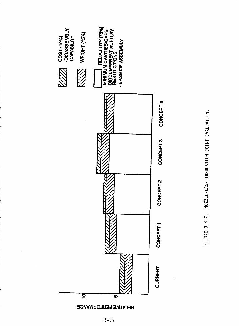
,,_,_ n-O
--_u- 0
B I 1_9""_,
\
\
::mOl4_Vl_C)_3d=mAl14rB_
0o
0o
I.UoZ0(&
1110z0o
iiin-n-
O
o
_J
_J
Z
o
Z
I--
---7
Z
(...)
I.,61.--.I
f".l
C_
L_r,,,"
3-65
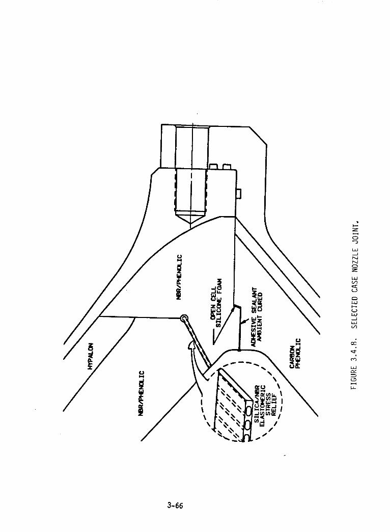
\\U
Z
0
LLJ.Jr_JPM
Z
i,i
U
L_JF--ULM..JLJJ
o;
c_
i,i
L_
LL
3-66
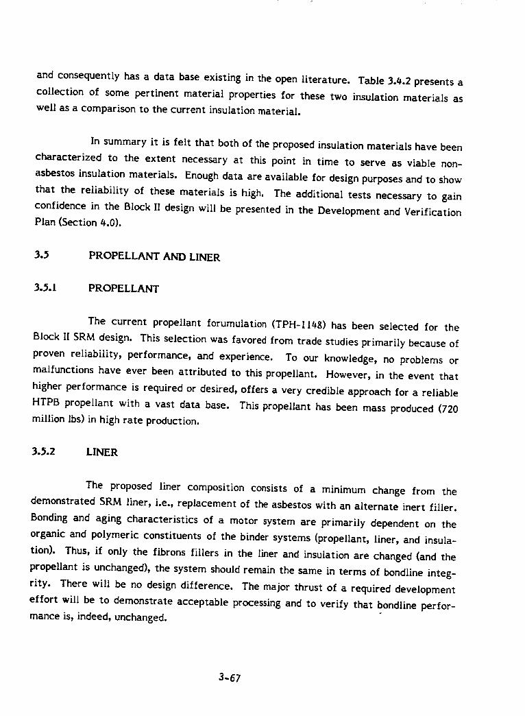
and consequently has a data base existing in the open literature. Table 3.it.2presents a
collection of some pertinent material properties for these two insulation materials as
well as a comparison to the current insulation material.
In summary it is felt that both of the proposed insulation materials have been
characterized to the extent necessary at this point in time to serve as viable non-
asbestos insulation materials. Enough data are available for design purposes and to show
that the reliability of these materials is high. The additional tests necessary to gain
confidence in the Block II design will be presented in the Development and Verification
Plan (Section _.0).
3._ PROPELLANT AND LINER
3.S. 1 PROPELLANT
The current propellant forumulation (TPH-II48) has been selected for the
Block II SRM design. This selection was favored from trade studies primarily because of
proven reliability, performance, and experience. To our knowledge, no problems or
malfunctions have ever been attributed to this propellant. However, in the event that
higher performance is required or desired, offers a very credible approach for a reliable
HTPB propellant with a vast data base. This propellant has been mass produced (720
million Ibs) in high rate production.
3..%2 LINER
The proposed liner composition consists of a minimum change from the
demonstrated SRM liner, i.e., replacement of the asbestos with an alternate inert filler.
Bonding and aging characteristics of a motor system are primarily dependent on the
organic and polymeric constituents of the binder systems (propellant, liner, and insula-
tion). Thus, if only the fibrons fillers in the liner and insulation are changed (and the
propellant is unchanged), the system should remain the same in terms of bondline integ-
rity. There will be no design difference. The major thrust of a required development
effort will be to demonstrate acceptable processing and to verify that bondline perfor-
mance is, indeed, unchanged.
3-67
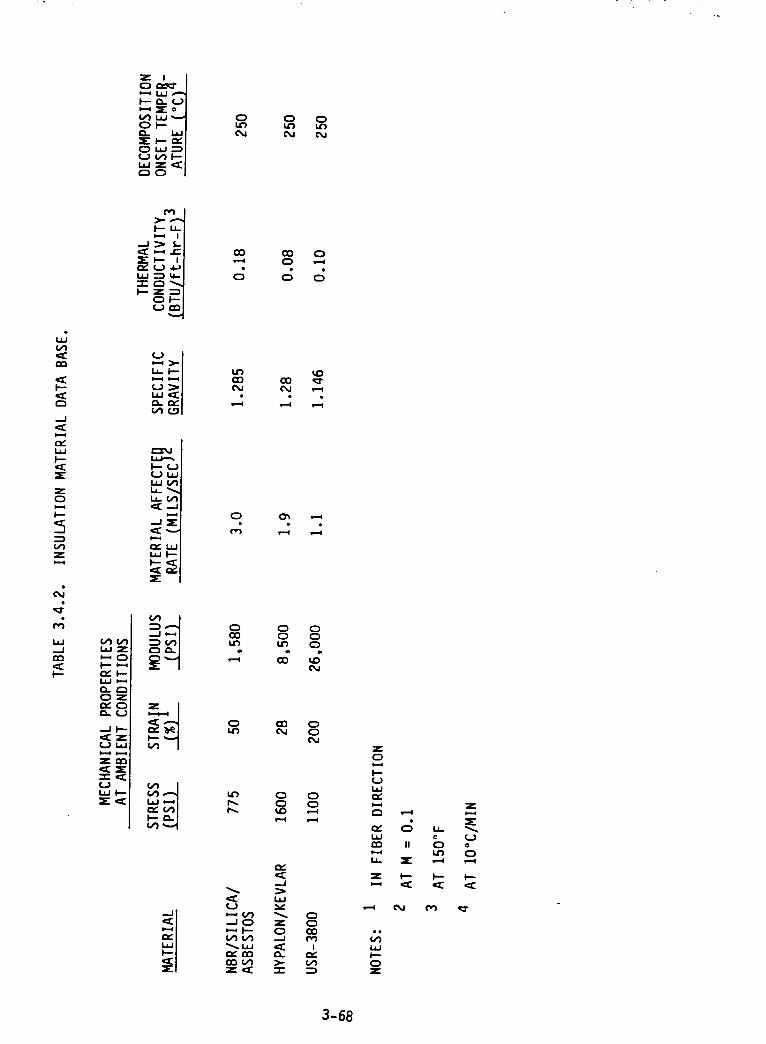
Z IC:) CL_"
0-_:E
_O
Q Q
F--
ZQ
Z
¢'__- ._-._I'--"1-.., I
,'_ <..)
_z_
b-, O
UI._J
s.-=i
O
0
Q
_-*V1
VIV)
P_" l=On'_V)
O00
0
COe_a
cr_
00
CO
CO(M
0
C_
..J
ZQ
>-"-r-
Q
c;
C_OC3
UC)CM
O0C_J
OC:)
OC3CO
Irv,
ZO
(J
r,,
P_
laJrr_
la.
Z
p-
Z
Z
c;II _) Uo
Q
I--- I_ t---(E _E ,:l:
3-68
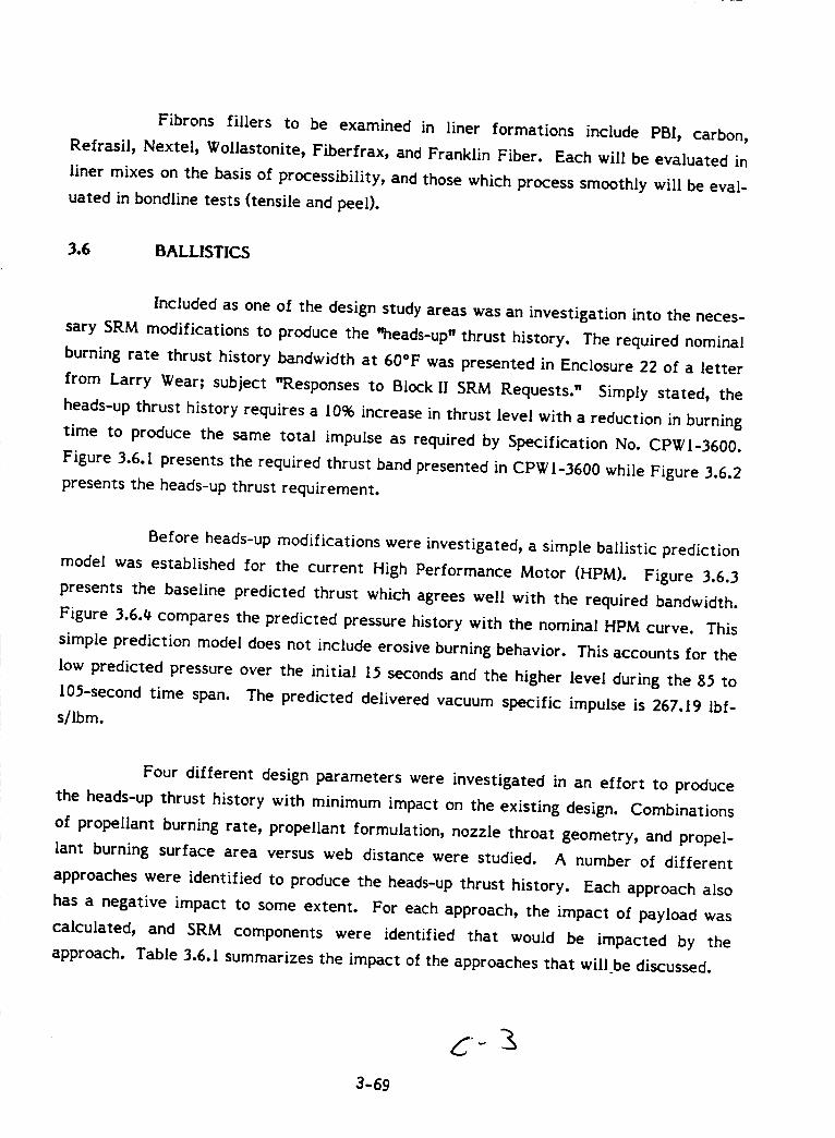
Fibrons fillers to be examined in liner formations include PBI, carbon,
Refrasil, Nextel, Wollastonite, Fiberfrax, and Franklin Fiber. Each will be evaluated in
liner mixes on the basis of processibility, and those which process smoothly will be eval-
uated in bondllne tests (tensile and peel).
3.6 BALLISTICS
Included as one o( the design study areas was an investigation into the neces-
sary SRM modifications to produce the "heads-up" thrust history. The required nominal
burning rate thrust history bandwidth at 60°F was presented in Enclosure 22 of a letter
from Larry Wear; subject "Responses to Block It SRM Requests." Simply stated, the
heads-up thrust history requires a I0% increase in thrust level with a reduction in burning
time to produce the same total impulse as required by Specification No. CPWI-3600.
Figure 3.6.1 presents the required thrust band presented in CPWI-3600 while Figure 3.6.2
presents the heads-up thrust requirement.
Before heads-up modifications were investigated, a simple ballistic prediction
model was established for the current High Performance Motor (HPM). Figure 3.6.3
presents the baseline predicted thrust which agrees well with the required bandwidth.
Figure 3.6.4 compares the predicted pressure history with the nominal HPM curve. This
simple prediction model does not include erosive burning behavior. This accounts for the
low predicted pressure over the initial 15 seconds and the higher level during the 85 to
105-second time span. The predicted delivered vacuum specific impulse is 267.19 Ibf-
s/Ibm.
Four different design parameters were investigated in an effort to produce
the heads-up thrust history with minimum impact on the existing design. Combinations
of propellant burning rate, propellant formulation, nozzle throat geometry, and propel-
lant burning surface area versus web distance were studied. A number of different
approaches were identified to produce the heads-up thrust history. Each approach also
has a negative impact to some extent. For each approach, the impact of payload was
calculated, and SRM components were identified that would be impacted by the
approach. Table 3.6.1 summarizes the impact of the approaches that will be discussed.
3-69
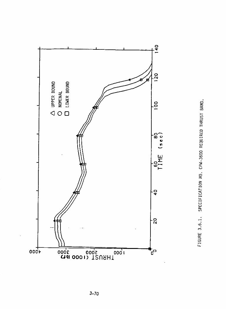
000_
I ! I
<3O[3
1 t I
ooo£ ooo_ oooloqf oool) ISA_HI
o
0.0
.0""CO o
qD
LLJ
I--
0
0(%1
@
Z
r_
I--or)
r.,-"t-I--
O=
CZY
r,,.
00tOCO
I
r_
Z
Z0
I--
1,
¢Y
i,
3-70
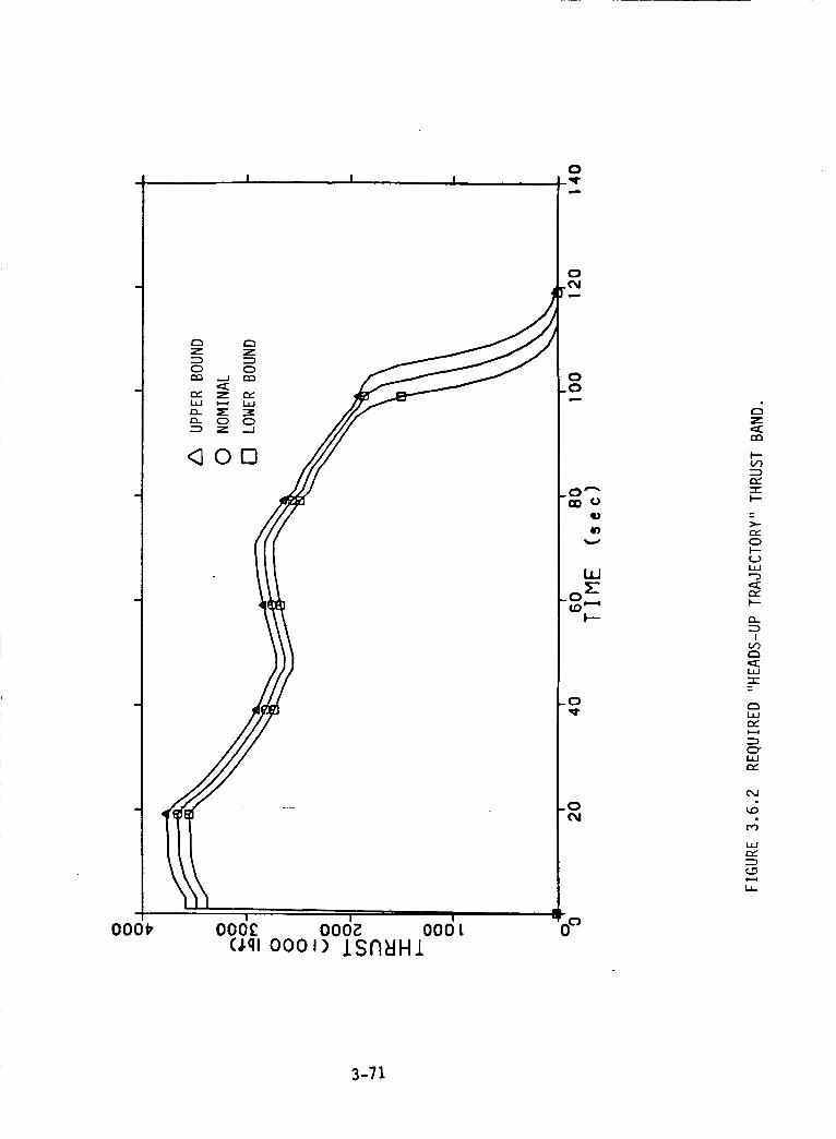
000_
I I I
<000
l I I
ooo_ ooo_ oooL(Jql 0001) ISfIBHl
0,q.
0
0.0
OD 0qL)
i,i
I--
-0,q-
_0
@
Z
I---
.-_eY"-r-I--
t---
!
C_i,ie_
3-71
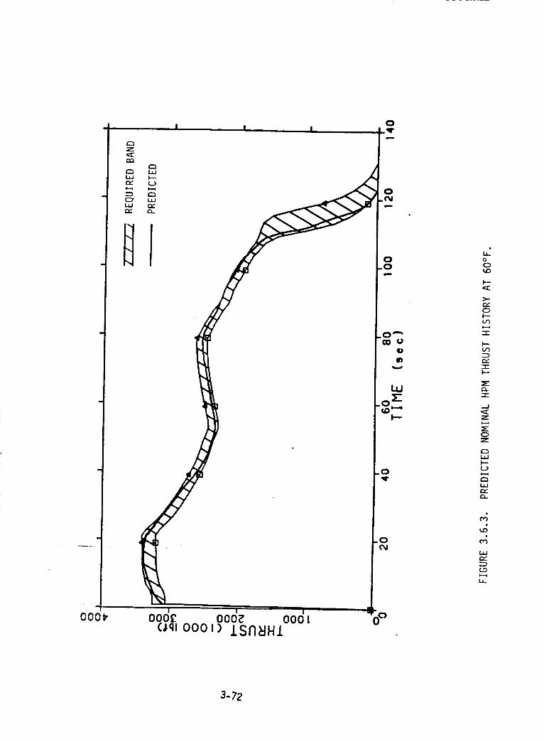
000_
, I I I
z_
x4
I ! I OCjloooc ooo_ ooot(Jql oooi) ISN_HI
o0_0
_--_:_
C_
"-r"
Cz=
.-J
Z
0
r_L_
LLJ
ILl
1.1_
UuJ
l_J
I--
o0_0
f.-
>-¢3g0I--
-t-
L._
:Z)
L_J
F--CO
"l-In
ZIZ
.-J
0Z
(:3
I--
G3
3-73
Z
I--
C_
l-et')
=_-ll
0,.
!
C_
'=I-
Ll-
>-
:DC_
O0
,,t.-I
i=--
O-
O0
_0
O0C_
e,
C_
!
O0O0
!
_0 O0 O,J
v
t-
F--_Z e-
Z _---
.
r,,J
co
4-
_or,,,..
÷
_0
cO E Z
___- _r_,,, _,-
_._ "7"
r_ _-_
'_'__" "_ --J E
llZ I-- '",--.
..._ -r" .J I-- 2Z
__ r_
._IZ
',' :E::
O0
_.. I.I.I
I*--', '
_Z_
Z_
_Z
,,, C.O"_Z
_"_,__,_:_l.ul
,o')X
_J ...J
f_4N ,"',OZZ_
_JZ
Z
Z__jr_
_--,.,
,,, _-_t_Jt_jm__-_
Z_--_._Z_--_
Zt._J0 "-"_. t_J
(_>
m_
m_
O"
0
r_
0.-I
c=
I..id
Z
Z
Z
,y
I...ul
3-74
The first approach investigated was to merely increase the burning rate of
the current propellant. This can be accomplished by adjusting the amount of iron oxide
(Fe20 3) and/or the ground to unground ratio of ammonium perchlorate (AP). The
required base burning rate at 62S psia and 60°F was determined to be 0.386 in/s com-
pared to the current 0.362 in/s baseline. Figure 3.6.5 presents the predicted thrust
history based on a burning rate of 0.386 in/s.
While the required thrust band is achieved, this approach would increase
MEOP to approximately 1,120 psia. The increase in MEOP would prohibit use of existing
hardware. The required increase in case wall thickness if D6AC steel is retained would
result in an approximate l,g00 ibm payload capability loss. If an alternate case material
such as 250 maraging steel with a heat treat of 210 ksi or greater is used, the existing
case wail thickness can be retained and essentially no payload loss would be required.
This approach will involve no additional redesign or development beyond the concept
currently proposed for the Block It SRM.
The second approach also involved an increase in burning rate, but nozzle
throat area was also increased to retain MEOP at its current level. The required burning
rate and initial throat diameter were determined to be 0.399 in/s and 56.490 in., respec-
tively. Other minor nozzle modifications would include re-optimization of the nozzle
exit cone contour and use of a carbon phenolic material with a fifteen percent lower
nozzle erosion rate.
While satisfying, in general, the required thrust band, the resulting delivered
specific impulse is reduced to 265.24 Ibf-s/Ibm from the current 267.19. The loss of 1.95
Ibf-s/lbm delivered specific impulse results in a payload reduction of 1,560 Ibm. Also,
the increase in nozzle throat diameter is sufficiently large enough to require the redesign
of the metal back-up structure of the nozzle.
The third approach investigated was a nozzle throat diameter reduction. Like
the first approach, this method will increase MEOP. However, the nozzle diameter
reduction will increase the delivered specific impulse. Also, the reduction will struc-
turally allow the use of carbon-carbon as the nozzle throat material (lower erosion rate)
within the envelope of the existing metal parts. The nozzle diameter required for this
approach is 51.0 inches.
3-75
I"--4
O0
c5II
Z
m,oO
0I--
i,.-4
I--¢./')
"-rI--
Ic,')
-r
m,iI"-
i--,4
W
_A
¢.,,.5
I.i.I
i.-=4
m,
3-76
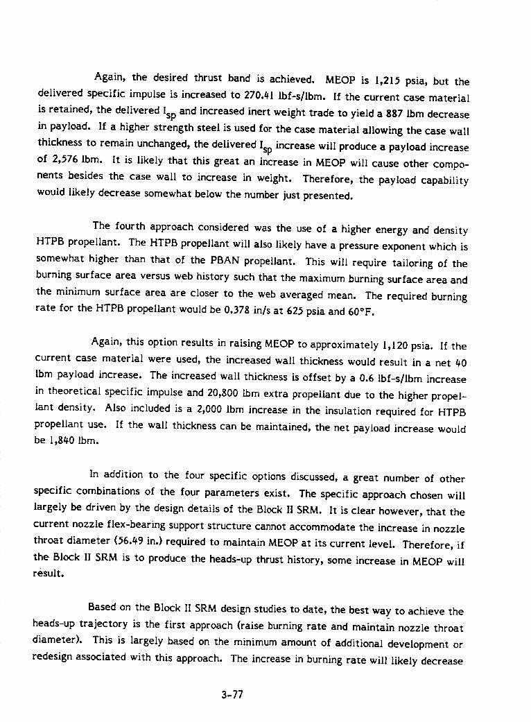
Again, the desired thrust band is achieved. MEOP is 1,215 psia, but the
delivered specific impulse is increased to 270.41 [bf-s/lbm. If the current case material
is retained, the delivered Isp and increased inert weight trade to yield a 887 Ibm decrease
in payload. If a higher strength steel is used for the case material allowing the case wall
thickness to remain unchanged, the delivered Isp increase will produce a payload increase
of 2,576 Ibm. It is likely that this great an increase in MEOP will cause other compo-
nents besides the case wall to increase in weight. Therefore, the payload capability
would likely decrease somewhat below the number just presented.
The fourth approach considered was the use of a higher energy and density
HTPB propellant. The HTPB propellant will also likely have a pressure exponent which is
somewhat higher than that of the PBAN propellant. This will require tailoring of the
burning surface area versus web history such that the maximum burning surface area and
the minimum surface area are closer to the web averaged mean. The required burning
rate for the HTPB propellant would be 0.378 in/s at 625 psia and 60°F.
Again, this option results in raising MEOP to approximately 1,120 psia. If the
current case material were used, the increased wall thickness would result in a net 40
Ibm payload increase. The increased wall thickness is offset by a 0.6 Ibf-s/Ibm increase
in theoretical specific impulse and 20,800 Ibm extra propellant due to the higher propel-
lant density. Also included is a 2,000 Ibm increase in the insulation required for HTPB
propellant use. If the wall thickness can be maintained, the net payload increase would
be 1,840 Ibm.
In addition to the four specific options discussed, a great number of other
specific combinations of the four parameters exist. The specific approach chosen will
largely be driven by the design details of the Block It 5RM. It is clear however, that the
current nozzle flex-bearing support structure cannot accommodate the increase in nozzle
throat diameter (56.49 in.) required to maintain MEOP at its current level. Therefore, if
the Block It SRM is to produce the heads-up thrust history, some increase in MEOP will
result.
Based on the Block II SRM design studies to date, the best way to achieve the
heads-up trajectory is the first approach (raise burning rate and maintain nozzle throat
diameter). This is largely based on the minimum amount of additional development or
redesign associated with this approach. The increase in burning rate will likely decrease
3-77

the amount of erosive burning somewhat. This will help reduce the MEOP increase from
1,015 to a value somewhat below the 1,120 psia level which assumes the same erosive
burning e[fect. Also, at this point, it is likely that a steel with a higher strength then
D6AC will be suggested [or the Block II design. These [actors along with some minor
burning surface area adjustments in the head-end segment should combine to signifi-
cantly reduce the 1,800 Ibm payload loss that was associated with the first approach.
3-78
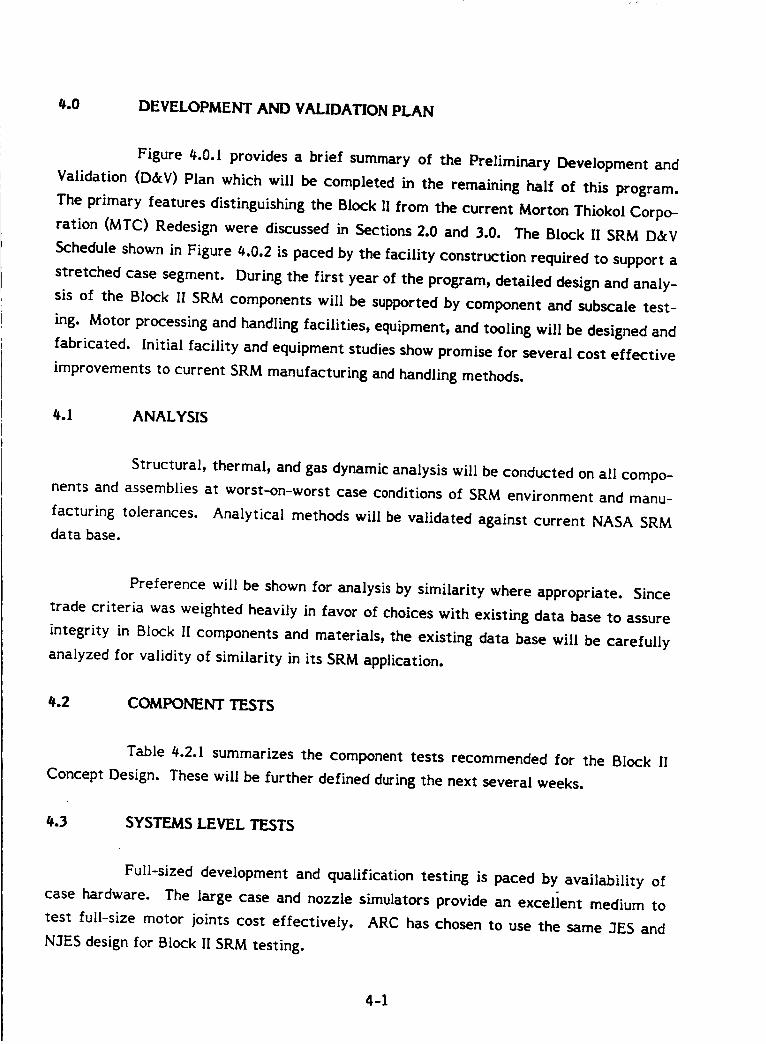
4.0 DEVELOPMENT AND VALIDATION PLAN
Figure _,.0.1 provides a brief summary of the Preliminary Development and
Validation (D&V) Plan which will be completed in the remaining half of this program.
The primary features distinguishing the Block II from the current Morton Thiokol Corpo-
ration (MTC) Redesign were discussed in Sections 2.0 and 3.0. The Block II SRM D&V
Schedule shown in Figure _.0.2 is paced by the facility construction required to support a
stretched case segment. During the first year of the program, detailed design and analy-
sis of the Block II SRM components will be supported by component and subscale test-
ing. Motor processing and handling facilities,equipment, and tooling willbe designed and
fabricated. Initialfacilityand equipment studiesshow promise for several cost effective
improvements to current SRM manufacturing and handling methods.
4.1 ANALYSIS
Structural,thermal, and gas dynamic analysis willbe conducted on allcompo-
nents and assemblies at worst-on-worst case conditions of SRM environment and manu-
facturing tolerances. Analytical methods willbe validated against current NASA SRM
data base.
Preference will be shown for analysis by similarity where appropriate. Since
trade criteria was weighted heavily in favor of choices with existing data base to assure
integrity in Block II components and materials, the existing data base will be carefully
analyzed for validity of similarity in its SRM application.
4.2 COMPONENT TESTS
Table 4.2.1 summarizes the component tests recommended for the Block II
Concept Design. These will be further defined during the next several weeks.
4.3 SYSTEMS LEVEL TESTS
Full-sized development and qualification testing is paced by availability of
case hardware. The large case and nozzle simulators provide an excelient medium to
test full-size motor joints cost effectively. ARC has chosen to use the same 3ES and
N3ES design for Block II SRM testing.
4-1
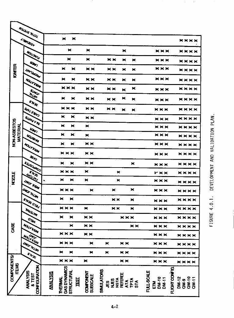
Z
--J
z0
c_
J
z
t.---z
o.o
L_J
r_
0
,,:::f
L_JC_
4-2
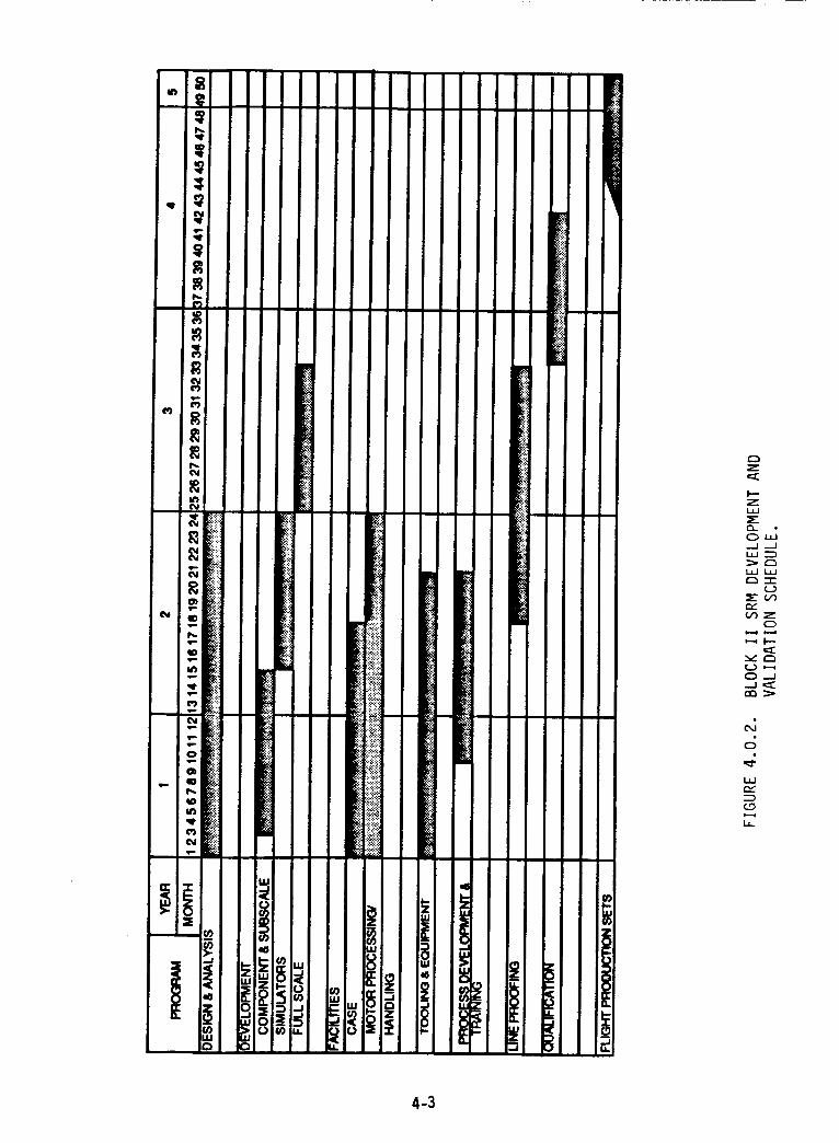
i'i_.i! _iii I
Z
h--Z
o,,___J __lL_
t_nlZ
r_
0
O.--J
c5
L_r_
l.I..
4-3
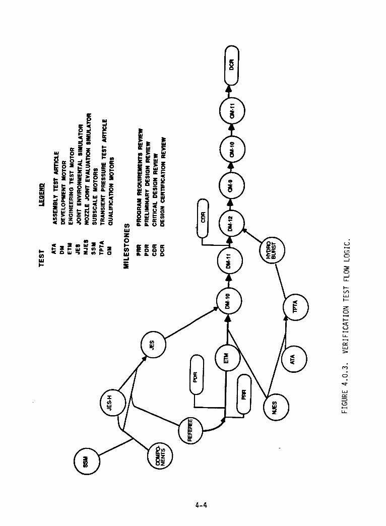
0,,._I
0
I--
ILl
ZC_
I--
c_
L._
4-4
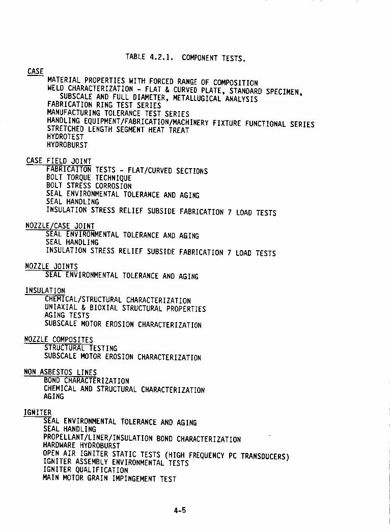
TABLE 4.2.1. COMPONENT TESTS.
CASE
MATERIAL PROPERTIES WITH FORCED RANGE OF COMPOSITION
WELD CHARACTERIZATION - FLAT & CURVED PLATE, STANDARD SPECIMEN,SUBSCALE AND FULL DIAMETER, METALLUGICAL ANALYSIS
FABRICATION RING TEST SERIES
MANUFACTURING TOLERANCE TEST SERIES
HANDLING EQUIPMENT/FABRICATION/MACHINERY FIXTURE FUNCTIONAL SERIESSTRETCHED LENGTH SEGMENT HEAT TREAT
HYDROTEST
HYDROBURST
CASE FIELD JOINT
FABRICAITON TESTS - FLAT/CURVED SECTIONS
BOLT TORQUE TECHNIQUEBOLT STRESS CORROSION
SEAL ENVIRONMENTAL TOLERANCE AND AGING
SEAL HANDLING
INSULATION STRESS RELIEF SUBSIDE FABRICATION 7 LOAD TESTS
NOZZLE/CASE JOINTSEAL ENVIRONMENTAL TOLERANCE AND AGING
SEAL HANDLING
INSULATION STRESS RELIEF SUBSIDE FABRICATION 7 LOAD TESTS
NOZZLE JOINTS
SEAL ENVIRONMENTAL TOLERANCE AND AGING
INSULATION
CHEMICAL/STRUCTURAL CHARACTERIZATIONUNIAXIAL & BIOXIAL STRUCTURAL PROPERTIES
AGING TESTS
SUBSCALE MOTOR EROSION CHARACTERIZATION
NOZZLE COMPOSITES
STRUCTURAL TESTING
SUBSCALE MOTOR EROSION CHARACTERIZATION
NON ASBESTOS LINES
BOND CHARACTERIZATION
CHEMICAL AND STRUCTURAL CHARACTERIZATION
AGING
IGNITER
SEAL ENVIRONMENTAL TOLERANCE AND AGING
SEAL HANDLING
PROPELLANT/LINER/INSULATION BOND CHARACTERIZATIONHARDWARE HYDROBURST
OPEN AIR IGNITER STATIC TESTS (HIGH FREQUENCY PC TRANSDUCERS)IGNITER ASSEMBLY ENVIRONMENTAL TESTS
IGNITER QUALIFICATIONMAIN MOTOR GRAIN IMPINGEMENT TEST
4-5
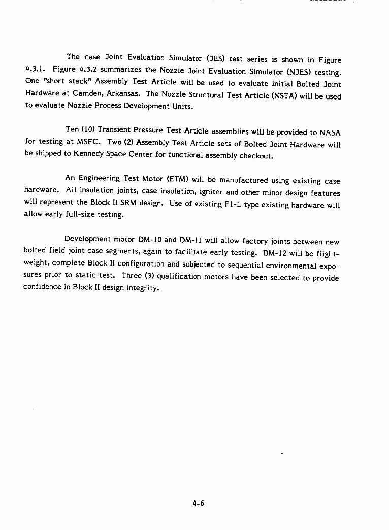
The case 3oint Evaluation Simulator (3ES) test series is shown in Figure
4.3.1. Figure /_,3.2 summarizes the Nozzle 3oint Evaluation Simulator (N3ES) testing.
One "short stack" Assembly Test Article will be used to evaluate initial Bolted 3oint
Hardware at Camden, Arkansas. The Nozzle Structural Test Article (NSTA) will be used
to evaluate Nozzle Process Development Units.
Ten (10) Transient Pressure Test Article assemblies will be provided to NASA
for testing at MSFC. Two (2) Assembly Test Article sets of Bolted 3oint Hardware will
be shipped to Kennedy Space Center for functional assembly checkout.
An Engineering Test Motor (ETM) will be manufactured using existing case
hardware. All insulation joints, case insulation, igniter and other minor design features
will represent the Block II SRM design. Use of existing FI-L type existing hardware will
allow early full-size testing.
Development motor DM-10 and DM-I l will allow factory joints between new
bolted field joint case segments, again to facilitate early testing. DM-12 will be flight-
weight, complete Block II configuration and subjected to sequential environmental expo-
sures prior to static test. Three (3) qualification motors have been selected to provide
confidence in Block II design integrity.
4-6
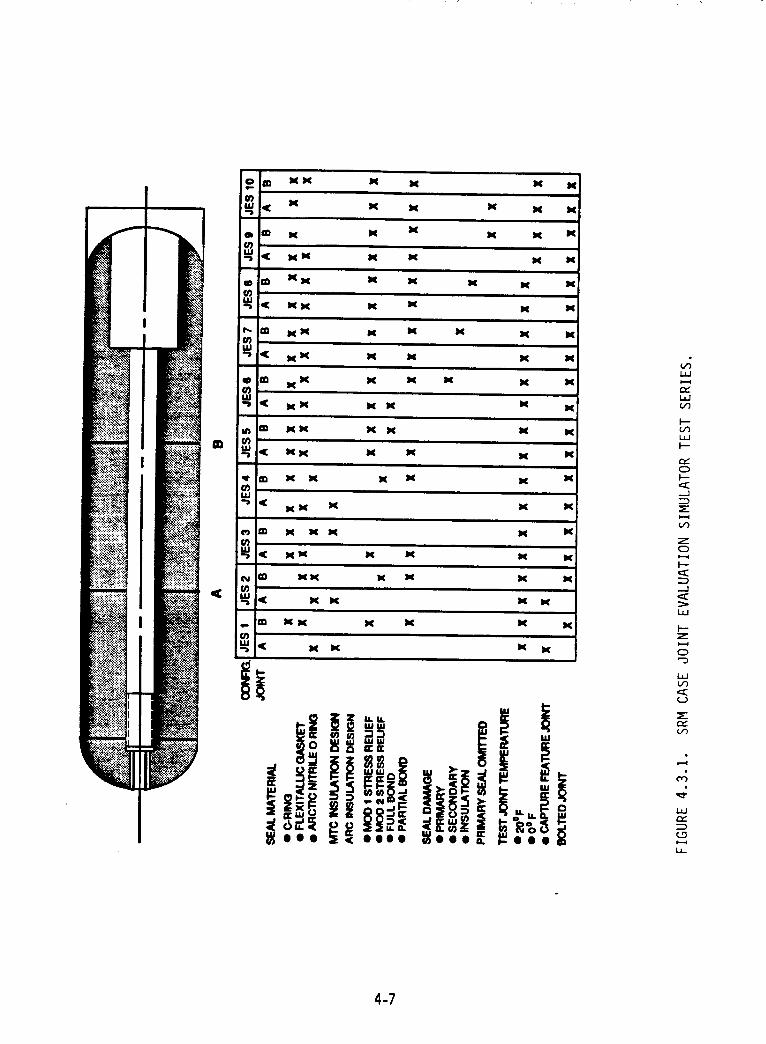
i,i
I'--
L,n
0
.--]
:Et,,--f
zo
I.-.
._.1
I---zt,-,,I
o
i,,(../-)
,,..,s(.,,.)
,---t
i,n
n,
4-7
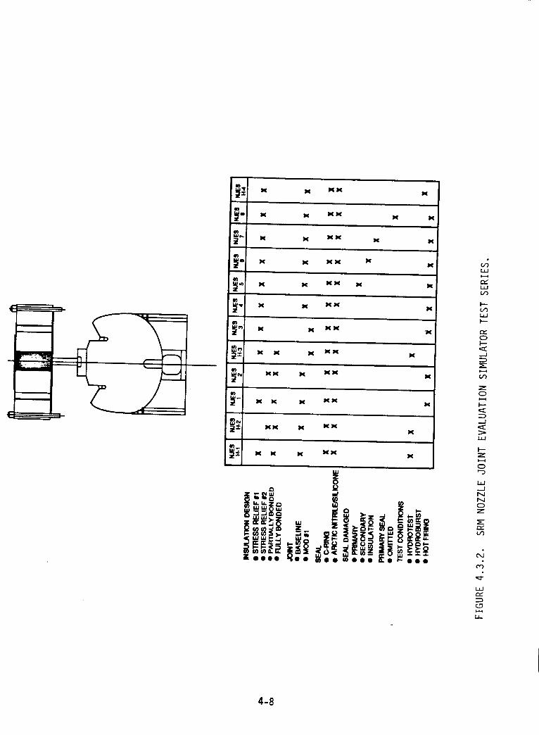
L_J
r_
I---
I--
r,,-0
._1
O0
0
--I
I--
0
0
(q,,4
4-8
5.0 STUDY COMPLETION PLAN
The remainder of the Block II SRM Concept Study Program will continue at
its planned accelerated pace. The program effort shown on Figures 5.0.1 and 5.0.2 is
currently on schedule and will continue to meet milestones and committments. The Final
Report shall be divided into two parts with Tasks 1.0 and 2.0 in Part I and Tasks 3.0 and
4.0 in the second.
5.1 TASK 1.0 DESIGN
The preliminary concept design discussed in Section 2.0 and 3.0 will continue
to be refined as supporting analysis is completed. 3oints/seals and nozzle design and
analysis will continue along with supporting analysis of the overall design. The Final
Concept Design will be reviewed by the ARC Technical Review Committee on December
I, 1986, and the Preliminary CEI Specification will be delivered by December 12, 1986.
The Conceptual Design Package will be completed and delivered before December 31,
1986.
5.2 TASK 2.0 D&V PLAN
The Preliminary D&V Plan will include component, subscale, simulator, and
full-scale test description and quantities. D&V Program schedule and Logic Flow will be
defined.
5.3 TASK 3.0 CAPABILITY ASSESSMENT
Assessment of existing and planned facilities and equipment will be
completed and submitted by December 12, 1986. This task will include a review of
handling, assembly, and transportation requirements and an assessment of environmental
protection issues.
5.4 TASK 4.0 BUDGETARY COSTS
ARC will prepare budgetary costs for Development and Validation, Facilities,
and Production Unit Costs within the Work Breakdown Structure defined in the contract.
5-I
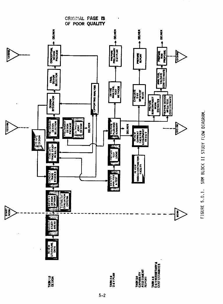
OF POOR QUALITY
I
I,.I
G
_K
E:D
O..JL__
F--
_j
O-J
LID
L_J
5-2
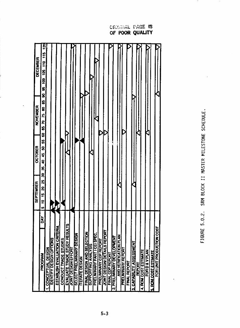
OF POOR QUALITY
_J
c_ILl-I-___
_JZ
L_J...J
L_k--t_
C_...J
C_O0
c_
ILl
(.0
LJ-
5-3
ADDENDUM TO
BLOCK II SOLID ROCKET MOTOR (SRM)CONCEPTUAL DESIGN STUDY
CONTRACT NAS 8-37295
MID-TERM REPORT
NOZZLE LINER MATERIAL TRADE STUDY
Liners used on the current SRM nozzle are fabricated from rayon-based
carbon cloth/phenolic tape. The performance of this liner material has been adequate
with the exception of anomalous gouging and "pocketing erosion",which was firstnoted
on STS-g. NASA and the current nozzle fabricatorhave spent considerable effort inves-
tigating the solutions to this problem and, as a result of stringent material/processing
controls and revised processing/fabrication techniques, have virtuallyeliminated the
incidence of pocketing erosion as demonstrated inthe six flightspreceding 5I-L.
The goal of the program study in this area was to investigate the use of
alternate state-of-the art liner materials to further reduce the possibility of pocketing
erosion. A material trade study was, therefore, initiated and the preliminary results
were given in Section 2.6 of the Mid-Term Report. This addendum presents the final
results of the trade study, which differ somewhat from those previously reported.
The materials considered for this application were other tape-wrapped, cloth-
reinforced phenolics and multidirectionally reinforced carbon-carbon advanced compos-
ites. In particular, the tape-wrapped materials were similar to the current material,
except that the cloth fiber is based on either a PAN or pitch precursor. These materials
are well known and have been evaluated in several alternate SRM nozzle material
studies. The advantages and disadvantages of these materials were discussed in Section
2.3 of the Mid-Term Report. The carbon-carbon material is somewhat newer, however;
thus, the following discussion of current carbon-carbon technology as it relates to the
SRM nozzle liner has been included.
The propulsion industry is continually seeking nozzle materials to increase the
performance of existing designs and to meet the demands of future vehicles. This has led
to the development of multidirectionaUy reinforced (three-dimensional and four-
dimensional) carbon-carbon composites, a material with good, uniform erosion resistance
and excellent thermostructural properties. Use of this material and its derivatives as a
single piece component in the nozzle throat and entrance has significantly elevated the
reliability and performance of solid rocket nozzles. Three-dimensional cylindrical
carbon-carbon integral throat and entrances (ITEs) are being used successfully on numer-
ous solid propulsion vehicles. Employing this material from the 2-inch throat diameter of
the Star 27 motors to the 15 inch throat diameter of the first stage Peacekeeper missile
A-1
TABLE 1. SOLID PROPULSION VEHICLES INCORPORATINGCARBON-CARBON INTEGRAL THROAT AND ENTRANCES.
VEHICLE C-C SUPPLIER TYP._..EE
NX STG 1 FHI, AVCO 3DSTG 2 FHI, AVCO 3DSTG 3 FHI, AVCO 3D
D5 STG 1 FHI, AVCO 3DSTG 2 FMI, AVCO 3DSTG 3 FMI 4D
IUS SRH 1 FMI 3DSRM 2 FMI 3D
STAR 27 FMI 3D30 FMI 3D
37XF FMI 3D37FM FMI 3D48 FMI 3D62 FMI 3D75 FMI 3D
SICBM STG 1 TBD 3DSTG 2 TBD 3DSTG 3 TBD 3D
SRAM II TBD 3D
TOMAHAWK EX 111 FHI, SEP 4D
MAGE 2 (FRENCH) SEP 4D
ARIANE V SEP 3D
IRIS (ITALIAN)
SCOUT-ANTARES
SEP, AEROSPATIALE 3D, 4D
SAI 4D
A-2
is established technology. Table I lists the solid propulsion systems presently incorporat-
ing three-dimensional carbon-carbon ITEs. Exceptional toughness, damage tolerance, and
defect insensitivity inherent with three-dimensional carbon-carbon (unlike conventional
two-dimensional laminates) have yielded ITEs with virtually I O0-percent reliability.
The application of carbon-carbon ITEs has predominantly been ballistic mis-
sile and space propulsion systems. However, the upper stage of the NASA Scout launch
vehicle incorporates a nozzle ITE of four-dimensional carbon-carbon, and the Ariane V
solid rocket boosters will incorporate ITEs of three-dimensional carbon-carbon. The
31-inch throat diameter of the Ariane V booster will make it the largest carbon-carbon
ITE employed to date.
The advent of automated preform manufacturing at both Fiber Materials, Inc.
(FMI) and AVCO Speciality Materials (the leading three-dimensional carbon-carbon
producers in the U.S.) offers further advantages of improved uniformity, producibility,
and reproducibility.Autoweave TM facilitiesexistingat AVCO are capable of fabricating
three-dimensional pre-forms of up to 90 inches in diameter. Fifty four-inch diameter
capability exists with FMPs Ultraloom TM facility.These woven pre-forms are typically
densified with a coal tar pitch precursor to achieve the finalgraphite matrix. It is this
stage of processing where scaleup issuesmust be addressed. Both FMI and AVCO subject
billetsto repetitive impregnation, high pressure carbonization (l,000 psi at AVCO and
5,000 to 15,000 psi at FMI)_ and 5,000=F graphitization. To accommodate nominal
_#-inch throat diameter shuttle SRM ITEs, facilityexpansion or alternative processing
must be realized.Also, the issue of a large R/T billetsurviving the process pressure and
temperatures warrants exploration.
Societe Europeenne de Propulsion (SEP) of France has taken a different
approach to the fabrication of three-dimensional carbon-carbon ITEs for Ariane boosters.
Utilizing conventional textile equipment and cost-effective chemical vapor infiltration
(CVI) techniques for densification, SEP has achieved an ultrafine weave (an order of
magnitude finer than conventional U.S. construction), three-dimensional carbon-carbon
amenable to large, economically produced billets. This technology is presently being
considered for transfer to the U.S. The largest U.S. graphite CVI capability (up to 93
inches in diameter) presently exists at B.F. Goodrich_s SuperTemp facility. This novel
three-dimensional carbon-carbon is presently receiving Air Force attention for potential
application as nozzle components for the SICBM.
A-3
SEP was requested by ARC to investigate the usage of their advanced mate-
rials for use in the Block II SRM nozzle. In reply, SEP kindly submitted the design study
below for use in this report.
SRM NOZZLE DESIGN WITH A CARBON-CARBON THROATAND
THERMOSTABLE INSULATORS
Submitted by: Societe Europeenne de Propulsion
The reliabilityof a nozzle ismainly a function of
the materials used in the throat area. A significant im-
provement could have been obtained over the past ten years
by the development of multidirectionallyreinforced carbon-carbon, but the main weakness of these carbon-carbon throat
nozzles is the phenolic insulators. Thermal expansion and
outgassing of phenolics are responsiblefor most of the firing
test problems; these two parameters are difficultto predict
because they are a function of heating rate, ply-orientation,
load state, process history, available vent path, and other
complex boundary conditions. In order to replace phenolic
insulators,SEP has developed new insulativematerials using athermostable matrix. These new materials are described in a
paper presented by Paul Donguy in the 21st 3oint PropulsionConference (AIAA-8_-II71). Different combinations of
reinforcement and matrix are possible: ceramic-ceramic,
ceramic-carbon, carbon-ceramic, and specially processed
carbon-carbon. Thermostable insulatorspresent the following
advantages:
1. A low and predictible thermal expansion.
2. No outgassing.
. Excellent structural properties allowing hightemperature attachments, such as thread orpins.
Today, a significantnumber of nozzles of various sizes,usingthermostable insulators,have been successfully tested atSEP.
Thermostable insulators are stillmore costly thenphenolics, but the design can be often simplified, thus de-creasing the nozzle assembly time_ moreover, the nozzlebehavior can be accurately modeled, eliminating failures indevelopment.
Two versions of the SRM nozzle using thermo-stable insulators are presented.
k-4
For each version, a preliminary thermal analysishas been performed assuming safety factors of 2.8 on ablationand 1.0 on char (thermostable insulators do not char in firing).
The insulative thicknesses have been determinedusing the following design criteria;
Maximum temperature elevation of
metallic parts (+ 50C after 130 sec)(+2300C after 540 sec)
The first version (Figure 1) uses our currentLtechnology ofthermostabie insulator (heat diffusivity 2.S 10 -° m=/s).
In this case, thermal thicknesses have been in-creased, compared to the current 5RM design, and newmetallic parts have been designed_ however, the flex bearingremains the same.
The second version (Figure 2) uses a new materialcurrently in development. This material already has beenfiring tested, but it has not yet been industrially manufac-tured.
2_ this case, the thermal diffusivity is0.8 10 -(; m s and the same metallic parts can be used.
In each case, thermostable Ln.su!ators are associ-ated with a NOVOLTEX carbon-carbon throat, NOVOLTEXhas been developed for exit cones_ however, its use for ITE'shas been already demonstrated! a NOVOLTEX ITEC has beenrecently demonstrated on a MINUTEMAN third stage underan RPL contact. This material is characterized by a fullyautomated preform construction, giving a three-dimensionalfine spacing texture.
The densification is achieved by a chemical vapordeposition process! few cycles are needed to reach densitiesgreater than 1.7 g/cc! the resulting matrix has good erosionand mechanical properties. A NOVOLTEX throat has beenselected for the nozzle of the ARIANE five solid rocket
booster (weight of propellant= 420,000 Ibm). The manufac-turing process has been already demonstrated at a three-fourths scale.
The carbon-carbon material and the alternative tape-wrapped materials were
compared to the current rayon-based carbon cloth/phenolic using the trade study meth-
odology described in Section 2.0 of the Mid-Term Report. The candidate materials were
compared on the basis of relative reliability, performance, and cost. Weighting factors
were assigned to each of these categories according to their relative importance as
A-5
o_ poor Qu_n'Y
_J NO_t'It _ _ llmJl,t l_iOcc I
FIGURE 1. SEP DRAWING ABD 11070+AA.
A-6
(_ Ni_VOtTE X C._BON-C,4Um0N (¢km,*y _.'/Og_cc I
(_ M_N f_'c'_Aili_lF INSUq.AIOR Ick,r_sJty l.rjoglrc|Ihe_ 61tu_v*ly 0.810 *m_$|
FIGURE 2. SEP DRAWING ABD 11071+AA.
A-7
follows: reliability, 0.6_ (6_ percent); performance, is 0.I_ (I_ percent); and cost, 0.20
(20 percent). The relative merit of each alternative was assessed, and a ranking score
from I to I0 was assigned. Multiplying the raw rankings scores by the weighting factor
in each category provided weighted scores that were summed to give a total for each
material.
In most categories, the materials were ranked qualitatively. In evaluating the
thermal margin category under reliability, the thermal analysis in Section 3.2.3.2 of the
Mid-Term Report was used.
The results of the trade study are shown in Table 2. As the table indicates,
the rayon-based and PAN-based materials received identical scores. Literature indicated
that the PAN-based material had a somewhat reduced potential for pocketing erosion.
However, this small advantage was offset by the less extensive database available for
this material compared to rayon-based material, the increased developmental risk asso-
ciated with a Wnew" material, and the slightly reduced thermal margin for the PAN-based
material. The performance gain exhibited by the PAN material did not overcome the
reduced reliability. With equal ranking, there is no reason to switch to the PAN mate-
rial.
Results were similar for pitch-based material, except that it exhibited an
even further reduced thermal margin to the point of impacting hardware design to meet
the safety factor requirements.
The low score received by the carbon-carbon resulted primarily from the risks
associated with replacing a well developed material in an existing design. The develop-
mental risk and lack of an extensive data are the major drawbacks for reliability and,
combined with the increased cost, more than offset the increased performance.
ARC's conclusion, then, is to retain the current nozzle liner material.
A-8
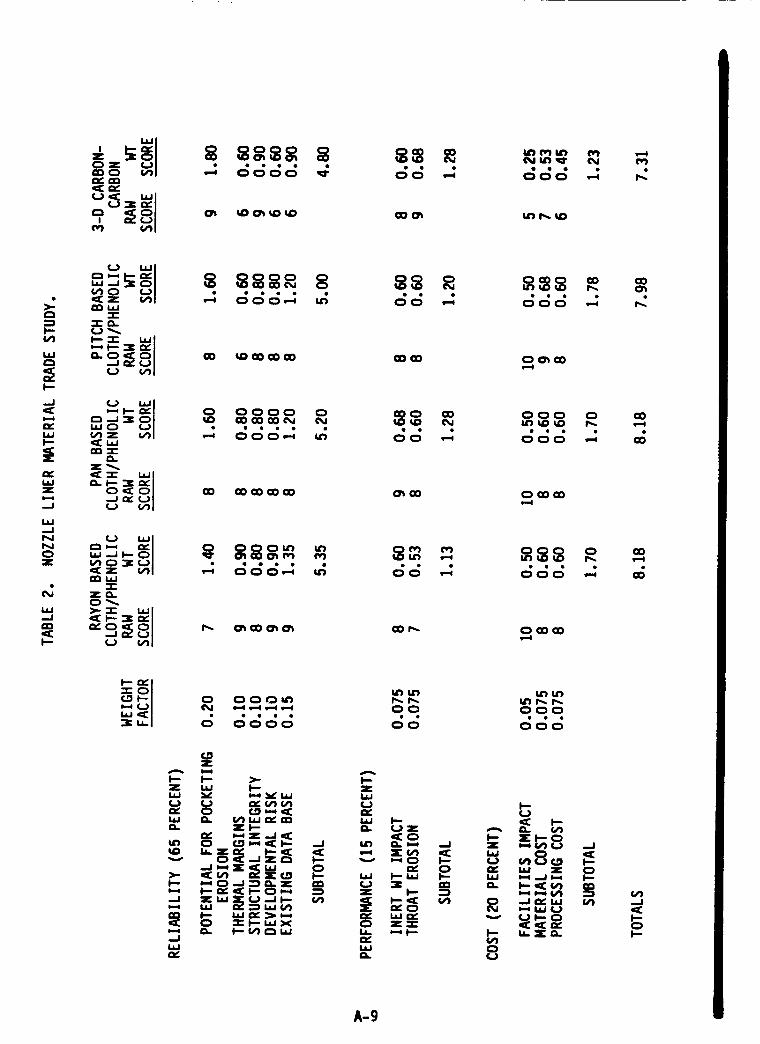
>=
p-v)
F--
_J
wF--
z
._J
ILl--JNN
:Z
IdJ--J
I--
.=1
A-9
APPENDIX B
SEAL DESIGN/PERFORMANCE INFORMATION
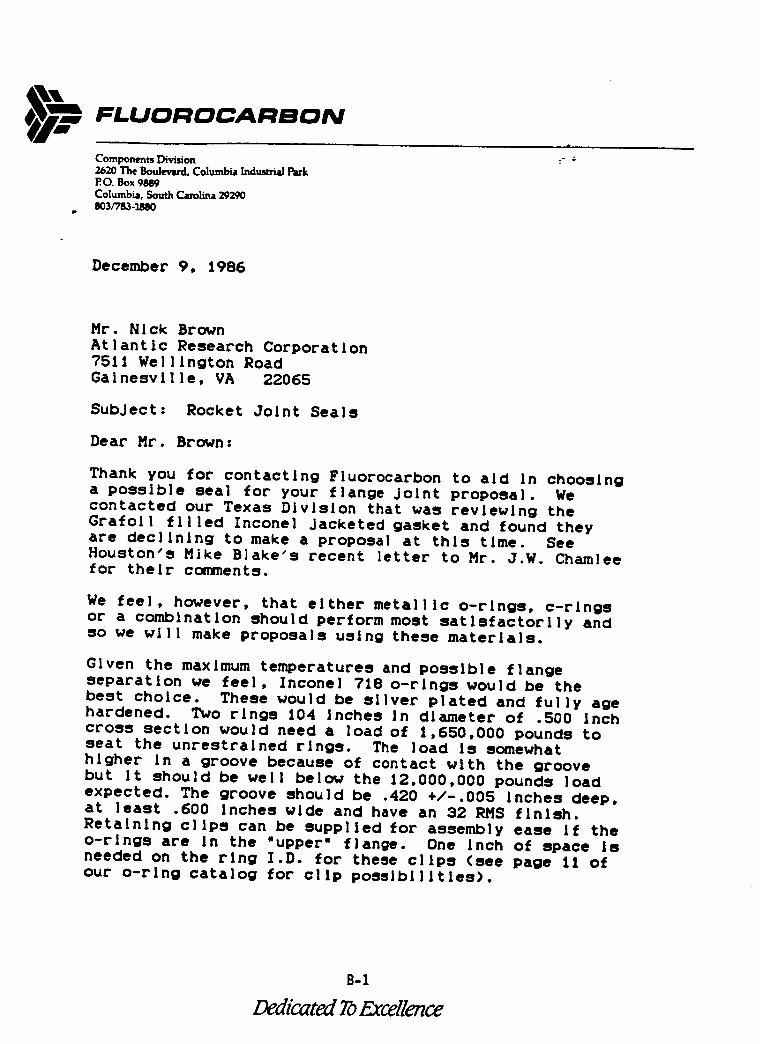
FLUOI:IQCAI:IBON
Components Division2630 The Boulevard, Columbia Industrial ParkR0. Box 9889Columbia, South Carolina 29290gO3/TS3-11_O
December 9, 1986
Mr. Hick Brown
Atlantic Research Corporation7511 Wellington RoadGalnesvllle, VA 22065
SubJect: Rocket Joint Seals
Dear Mr. Brown:
Thank you for contacting Fluorocarbon to aid In choosinga possible seal for your flange Joint proposal. Wecontacted our Texas Division that was reviewing the
Grafoll filled Inconel Jacketed gasket and found they
are declining to make a proposal at this time. SeeHouston's Mike Blake's recent letter to Mr. J.W. Chamleefor their comments.
We feel, however, that either metallic o-rings, c-ringsor a combination should perform most satisfactorily and
so we will make proposals using these materials.
Given the maximum temperatures and possible flangeseparation we feel, Inconel 718 o-rings would be thebest choice. These would be silver plated and fully agehardened. Two rings 104 Inches in diameter of .500 Inchcross section would need a load of 1,650,000 pounds toseat the unrestrained rings. The load Is somewhathigher In a groove because of contact with the groovebut It should be well below the 12,000,000 pounds loadexpected. The groove should be .420 +/-.005 Inches deep,at least .600 Inches wide and have an 32 RMS finish.
Retaining clips can be supplied for assembly ease If theo-rings are In the "upper" flange. One inch of space isneeded on the ring I.D. for these clips (see page 11 ofour o-ring catalog for clip possibilities).
B-1
Dedicated ToExcellence
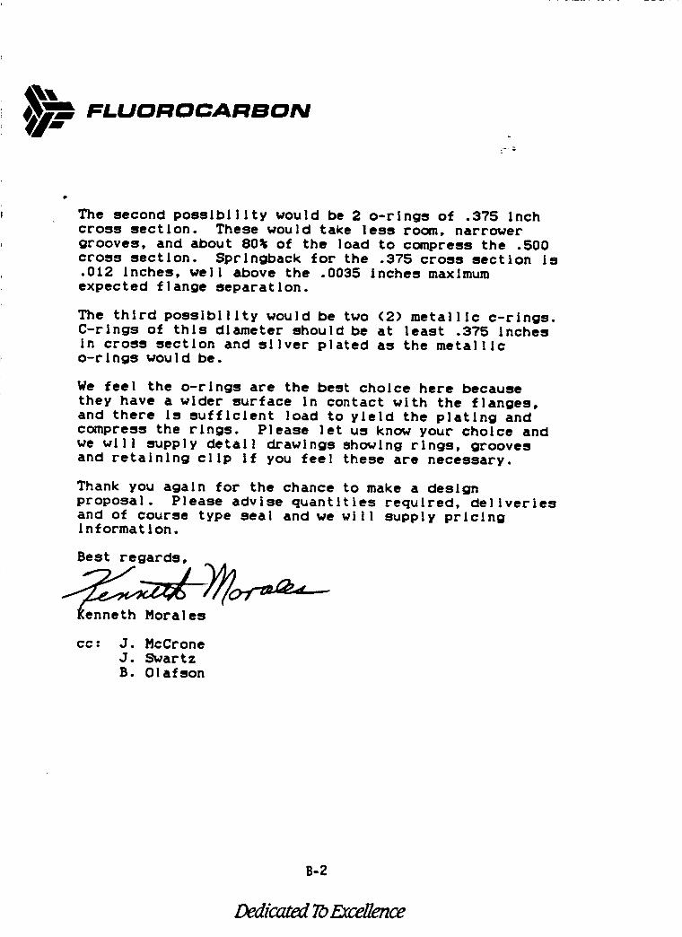
FI.UOROCAI:IBON
z-'i"
The second possibility would be 2 o-rings of .375 Inchcross section. These would take less room, narrowergrooves, and about 80% of the load to compress the .500cross section. Sprlngback for the .375 cross section Is.012 Inches, well above the .0035 inches maximumexpected flange separation.
The third possibility would be two (2) metallic c-rings.C-rings of this diameter should be at least .375 Inches
In cross section and sliver plated as the metallico-rlngs would be.
We feel the o-rings are the best choice here because
they have a wider surface In contact with the flanges,and there Is sufficient load to yield the plating andcompress the rings. Please let us know your choice andwe will supply detail drawings showing rings, groovesand retaining clip If you feel these are necessary.
Thank you again for the chance to make a designproposal. Please advise quantities required, deliveriesand of course type seal and we will supply pricinginformation.
Best regards,
cc : J. McCroneJ. SwartzB. Olafson
B-2
Dedicated To Excellence
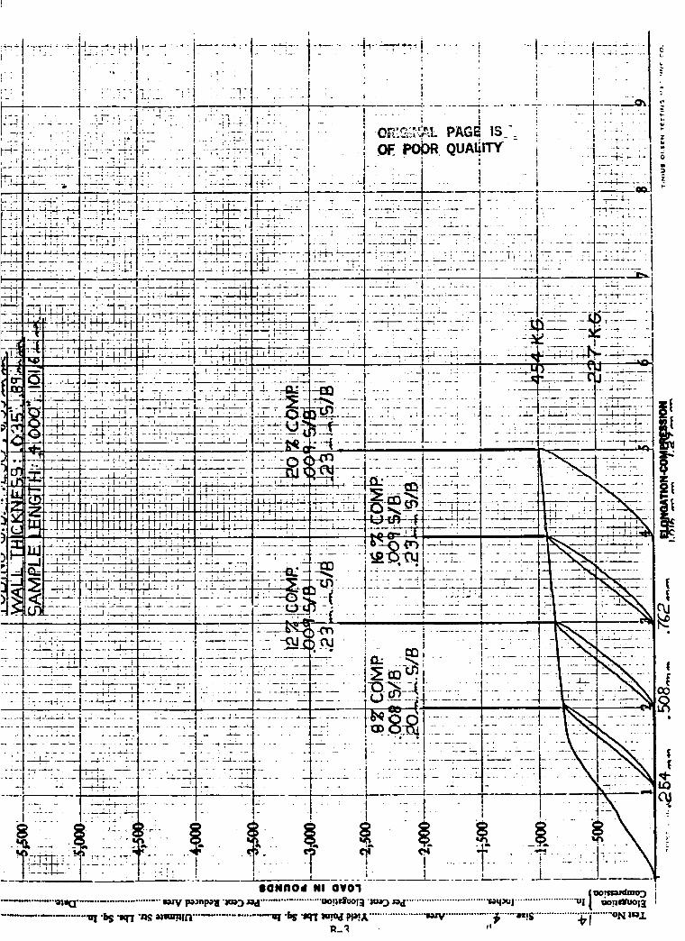
I i -
lI
I
" " , 77 ! .... :. : I ;q . _:
,. , .. ; "_ : . . _: __
_... ....... : ; ..... .-- T.1-̀ .... :- -.__..__. ....
i
" I I - "_ i
I! .
I -- ! .... I ....
i 7_ - " -: I
I , .
_ _;:--. .... _::_:iL.___:-.:J_:ZJ_ :-,.__,_-_- :: . Z: ..........
........ i
. I, !
='_._;_,'...,--LPAGE 13OF..PO_ QUAIIITY-; I
i
...... i
.__, ,.j_.+ .... j ........ . _ I•_.._ '---i-: ._---:1....... -- li_": ...._;_L;, :, . _- iJ-_ :....: :i :L_.I - _--_...... I=."J.-!-L._,
___.L:=..._....;_.,..___ _._:_:._._. 1;-- +..:-:-;--;.'.: _]__: '_L.I' " v;_ ' , I':'*;1;,
" ,"': : : _:" :I ': ':/ -- ':' "',__.__-:.-J'- .-.:.;.-,-'-L'-_-:-L--i- : L:' _.'-1-, :_. ' ; _ , 1 ' / ...;.l' ./ ',:Ii
, _'--"I, ---t-" .... I- "_'_ ,"t"--" 1 -'T_ ":'i_! .... "-_", ,-"T'T'___ :__._ ...... ,. __' ..--..-L_ ..... t .... _,-,-' ' ' '
_q-_._. ' '1-:'-"1-'.:: • .:.... :: ,,
, _i ,', _,-_1-; 7Tj_,; ,_I ___ r_ _ ---': ..--:*- - T"-" ._-:-" ,.--r--- 7 .... --I....... . .-:,.
-_ _'..,_,_"_J.'__,J _ _LLLL, :._- ..+z l- _•,u "it,_ 'v i ", " I. ,,'!l_I
[
1
, :::: ....-] ....
. • .... ._ ._
I ...... t '.i. _"........ I - -: ....... :- - --"7-. a_ .......... "1 . "- .'!--- 4.- :
• _"-I ......• I -_-_--'_I.............: I:..... __-;:::'..i I ---- ::-_--I:;:--:_4-: :-:--:.:-]-. :- I-- -:.:::
.,_.:.-_.;_ _ : ....... _._,_.__.J.__".-_ ; ..|._'_. _:.' .......... _;_.:_._;.'.....
-H-_-_--__........ -,':-t '. "" l.-...... I-:: ..... -......_-: ":"-+-"........... --:1-:-;-'- -".- _..... . ----v _ .-'m-.. .... ,-K_ .....__--------'-k- -_--r.-....... ! - :t_Z.__ -_- .......--_---' '- ........ _-I-- ......... t ..... -"W" - " --li.,I,_ " --- ....
_ .... -.- : i -I-- .... l -_ .... _::: ......
_ - .......... I............ -:-----. ---_- :-"7 --: .... I .............. "--q- "-r-..._l_.,=-z_-__-_-,---: ...... --l-- _7-: ....=___ .............. _. ..... __:__.... __rj__:__.,: • :, 7 7_']:-- 7-.: :_. r ._.;!' . I ' _L_:' ;J ' '_',-1._,_. I ' | _ .:._ . I ........ ..,_:._.J ._-;--,-. .....-- _.--" ""T-':-TI- "-': --:-"I-I_ 77-T-,'-m,.,- '-': ";--7 i":'"i_'-_,,--!% " -I ..... : - -I "'" ' ] ' : ' , '. I ' ; :_._ '-_ •,--T'---'"!"-"T: 7"i - , '---'-_':-""T'_7-:-,--,! : ," _ "" '-Lf') ". ...... ; ..... ' - : ; "7 .... ;-q:-;--_T:- ""Y--.'T:'.-" -_. _._L__,__---.--_-,--I-:.-,-..... I-L-......... ---_ O._]ff_-..-..---1 ..... _ ., I ............. -=-._.- ,]--++,-_--:--
_--71;-,-i-, .-;-I-:_i TT -_...... :7 .............. _"_ -_ ..................... ._[':_, ,-.-_-, __ ........ _ :__,_,_, ........ ,_................ '--:i--'-'- _:: : : • : -I:-:' r_, ',r("q -_ ....... I--- : -I ....... .---'_-'---:-1 ,: ".
,.,, _...___j.._-..._;.._...= .... -=_.L._J .,. - --I--'--.:_"I, r,¢,_ --I ............ I........ I "._ .... _.'_---I :=:--:-.LJ _ • :$:1 ______.____.__:_._.__;_.,.,_ .___i__I;__._._.__l_____' __.,_--..._ _. "_._IJ,,_ .... 11_"J_-I .... "I ........ 7 ...... , --!N_,. _'--a, I--" ' , , _ , ' I _ : I ' ' ' _ ' ' " _ I ' ' ' ' ' _ _ _'_"_l [ J .... L. - l-_,. .....
• "_ - ',,-IT, . . -_, • ,. , :-.. .-m , ---_- ..... :-1_ .... :: _--_G,, "_ I _l iill III II " I ; ; II I ! "''----'i : II''_it_' iI;_,,.._.___ 'L '' l-- II ':' _ i;' ;'%'-
,_, l;__._LI.U. Illl_lt_ I_j ; i.,,._._I:_:_;_..__._J___-'_L=_.,-_Z_2[.;._.__._,._;_ :_:_._._3J :-:--,.-r-_;J:-_\
I-- UJ .....,, '-'--_-'-......... --_--;-.. _:-I----. .... J ............. ' _-I ......................; . , , . ,'-*---.
: __ ,:._, _ ,_ _= . --=_--, .... ._ J .............. ........... I...............
>.-_U'L:-:_:,:._-___--_::-:__ ...... .--_-. _-4'--i , ......_,.......... ,_ ........ F........ ':........• " ...... ' ' " _" • I i ,
:.... -:-:- ,. ;_ i_ -: - ,-_-.--- -_'_-m i - i ......... l -:7:..._b<-_-::::.;:.... "_",'_--.'--'- --- .... _- :- .... ' " "-" ....... _ O,j " • ; -" . . ;I ,, _L. _. ____)_...... , ..... : :_'b,_'__-.......
-_-] --." ":: ..... '--_ ; - ..... I---=-;-............ -_-.--_---- i n. --_ ............ _.... _'_-' ......I ' ' ! ' ' • I__ _ _ I " ' J-- :, . I _ .._ " ' ...... I- .......... "_--"_ .....
.'T'_-- ;":':1--- -- :- . "-"1 ..... _"- : .... :" " " :- -- • " , - ' . '
::-z:- .:: :::.r: :- : -IR .......- I......... =b -t..... ]!--'--: .... "L"_.'/-I- ......... :--: ' r ......... l-'_"_'-dT ....... t ............. I.Z..... !" -' '-':'--,.,_
-.-:-I---_-,-'._:---_,:j__......... !:=--7!1--: .... _=-q...................... _.. _---::---..... t-'.... :-_- ......... :I ................. : ......... :-:, : ...... --::':.-:-:.....- _--'-"--I "_-':-: ....... L- -, .i-........ -: " . -- " • "..............
1"-: - --:Tt-_ ...................... t --- .i. " ::._ :-:::. t.:-_-:::+-i::. !- , v _ , _
I I I" ll_ .... i ' L t II I " .... i i J I i
IQNflOd NI OVO';I !
m_:1 ........................ _ pO_nl_! "low'j_ ......................"oop_uoi;i"m,rj _od ..............................."r,aq_ui ......................."Uli °°P_ru°l_ i
........ _ "_ ",m "n_m_mvn............... _ "_ ",m_ m:x....................._,v ................."_'"'"',,,:s................._'1"......°_ ;_
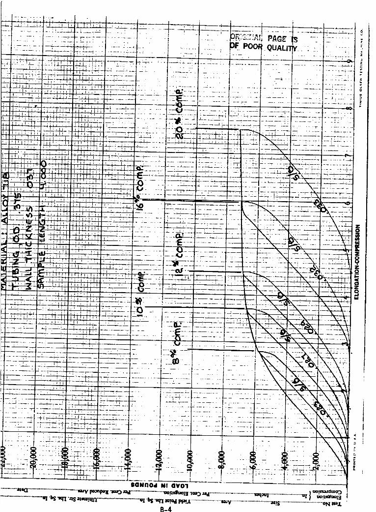
............. _ . °
I : _-_:1._ iil I I :
I
/
SONnOd NI or01
............ •_o _ _ _ uo_r, azdmo"j........ •a_q: I ........................... _'yp_-_rj_ ........... ._ F_'m;r'Jz'_! ............................. _q | ...................... "_I u°9_:_°13
B-4
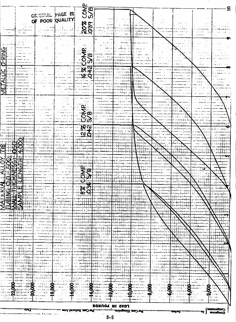
D.:
0_:_,_...,,_ _AG , ,, ,nJ , I i l
............ J ................. • I --
......... - . ..!_ .v.._ . ' ' ' " "1 .............._ ....J...... I . s _ __c,,',_=--- _T._-:;:_-_-_-:...... .-: - , --_,:1 .... - ........._t_ ...._-_ ........ I --! ....... i-_-_ .-T---:'--- _2_.'-:.-_£2-_ -_: ....:: :;: ._, :. " :.: ..-'--I--_ ..... i .... ' .... ! --.,.o-_ --_ -_ ........... _ __._........... ' IX _-
------- i ,, -' - ; --'X ..... i- -N:-:::_+_-:-- I _,__ _2__._ ..:_\_,:
--.- .... ,,.-7-- ........... ! ........... '_-_ .... --_--_-_F-_" --2_.:___ ________
........- ---:::--z-. ;;,: '.iii _;_I, ;2:=:':T_- -._--_- _-: .... = --_)___z-_-__ _/__:._ ,:,,:.,, ,.,,,,..: ,,==,. ,_.d:L__. -_. -._
• "" -. ..... .. .... T_ . ": -'--- - '.l;:J. __"-'_ .... _--_'_ '""-
-_ ; . - . . . ........ .. .... :.__..,__.____._._.___:._:.,__-- __!. _, ._"_)-,,," ......... " .... _-:_'_--'-'_------_.-_---_--_----_-_- _T.-_
_'i"*'_ ....................... I ..... :', . .,'; ',_ \ ... ,. _ ,..•_I-z--_- ................ -=-_.;.,:i' :, .,. :_ _, k' ; " .... :--.-_,_--_-._._N_-
- , • -- --i ...... -I- .-._.,_3,____..L__ , : , , ;i' _ , ,_ . ,__ , : '_ , _ " _L---_T-,_, __...... i ...... _. ._:.' _, : _ _', ,', 2_;, _'. \----T -_"
] _ ' ' ' I ,_ ' v i..,=" , ..... :I' : : _ " , : ,_.. ', , , "T: '_.T"-'--T--'-__-- _--;-.,---._-._(,_--
:_n , .... . . _T--r-r ,_ , : - ,. _,_.--T_----- . . .-N_ _---_' _.-- . ,:._-_._ _._. . ,_"-_ . , ,. .._I i_i , ,._ _---_-,,,-,-n,,_-!._-_l_._
_-_ , . ; ' I ,'_'- , .............. __ _ ! """ ;. , ' "_-'_-- _--_-----_ _-_ _ _ . _ , _.-i _ 'L-L-----:-I---. ............... 2' :-_':,..=: ' ; ! ! t !: • I _, ,. : , ' : - I ' x. ,_..,-._,.'_L____t . , _ ' . • ; ' • _ x --."T,,-!-'_-'---
__ " ' ' _ ' .... , ' i, !'1 II,_ _, I "l :%:i; ,_' I :,'1 i' -, " x_ _,iv,-TT-T--"=-"'. ----_ ' " , • , , , ' ' . , _ : ' . I ' , '
:',,_Ji'.',i ! _-_-_' .... _'/--_2 ';,'i___L._ iJ__b.:'.!!; X' ,\".,:_ ,.i_ "i' __, :; ii:'- U.'I_ '_: I. ' -' ' .... ';, _ ; l:ili',l -'1 _ i_---%_--'"_--:_-- "--_'-:-_'-,-'_ ___ .'-_-t',, ,Pr"_,-,"--"l"_ ........... -.-:- _ ..._---J L ' ' L'-,L..I_ : , V ' = _ ' I , _ _ " _--_._ ' ' ' _, " ' : ' " Ik' I I j I t ', ',
, ; , , . !! ', :, .. . _-- _ -,. __ -- ,_._;. ., , l., , , . , !ill' ,, ,I,i ,. ._I,. _"_ ,_.!, \\.I ........ _._-
2_ ! 4 ....... L L_ 111 i%7_ V _ ii_ "_.___.':________,_ _ _ _ . , 1 . , _ I!%_' : , ', :_T I.................. -----+_,'''L ....... _,_.... ' __,=..___']...',_..' .... ---'_,
, _ , , , , , , , , _ , - __ --. .
........ -:-.............. -r---:_ . ' _ : , : .... i:! .... ;. . . .x.__;,_,.lX'._ ._Z.jj_.,_ 2. ,__L.X._ _,--F-- I ----_-_--_ ........ :.-_. 1 ;,,--_-' ',';' *_ '-:_.. ; ,.=:_,,11,I. _%_.. .._;x_:
• ' . t , i i i ! ! . I . _ • . ' _ • i _ " - :
--:.--.-,-J-4----l--- ........ " , _J- , _ '_.L ........ ! I _, _N. _! ,If: '_. • . . , - ..... _.: _, l-.-r-- ........ _.-._._-. _. _,_, , ='_ _l_l '_' , , ' ', i', ': ' ' ' ' ' ' ' _ l 11 i i all
-:-_-'.----! .......... _ ...... _-_--k_ .... ±.: _-£_._-_ .... ;_...... _..,_,;_;_:_ :, ._ , ;x\ i, .... "---_T-'- ;- I ..... -....... -' ....... . ..... __L_._:____.L_:.LL.':21__.__ ....... __ '_ _ _--."_-_--_-
. : I.__,_._L_____ ... . ._:',1 'l' : '_ ,,I ; I ; ' ' . .1' ' '_" i'_' II l''i'
"---i * .... • ...... r-.-----_--- ...... ---,-_--_--_:' .... _-- _--_;-_. _ ' ' ' ' ' ! I ' ! i • _ _ • i : : l_ _ .... '-._-,:_I--.._-.L------- -.,± ...... :._--'--L.,-" _ : ;_ --'' t .:" -' ,_--'T---- ......... _--'7;-----:-. --'._'_.' ,i -3 -_ .... _;--", • _ _ / • . ..... i _ ; -'T , . -- .... "C'_'-;---_-- -- .--_--_--- ......... -Hi-i,-_- ---_--_-_-,m- ,_---_-_.' ...."_'rT_'-- -- "'--_ "- .... k ......... _ _ _' _---- "-- _ _--_---- ...----....t-- -- " ' .--f ...... " '' ,, i,;_ III _' • ..
........__=_ ;_H_-'_ -_-;-;.'-;-;-H--:-.:_:L-:_- ........ _ '_ :', _, ;_L:_- _.,_\_t' I '_ _! I. ' ' , , . t ; , i ,v ' , ', , , . _.. ,
7- __._-'L 2_,_£ '._," _ :-_-
...... 2;- .... 2 - -.:._-" '_. _L _ : , ' i i , , _ . , i ; ,_ '_x_
--:'-''_-: .......... TT;---; -_-i":'_ ..... ,-'H-+ _-_..---._-_--,,- _- .... --r ...... : ..... . -: ..... --,-.'-.- .................. .'_-....\_,
• -_-T;-:i-_-S-:-'-: fi-' _"-'_ ":(3?-'- ..... r ¢>---"-_¢..F_-T.,_4-,---e _-:+_--_TC_- ..... .-- .c} ....... ," _-_-'_-----'- ,,_-X_----_I.--Z._]L%'--_£_'_;_ ........... >..... - " _-'_-" _" " " ' ''' _ ¢4-=-;---2-;_"_i'_' ' • ..... --T: _' ,,_ .... : _-" .... T:- _" -- _--+--__. ------r--_ ....... _ _.--_-,----_,,_-. -_ .... __;.
•--- .... -c_/-:£_ _ " " _ ....... ::-_-'-"__! ......... __E-...... o_ .... w_- ..... --._- - el' ..... -.
IGN_ NI OVO1
B-5
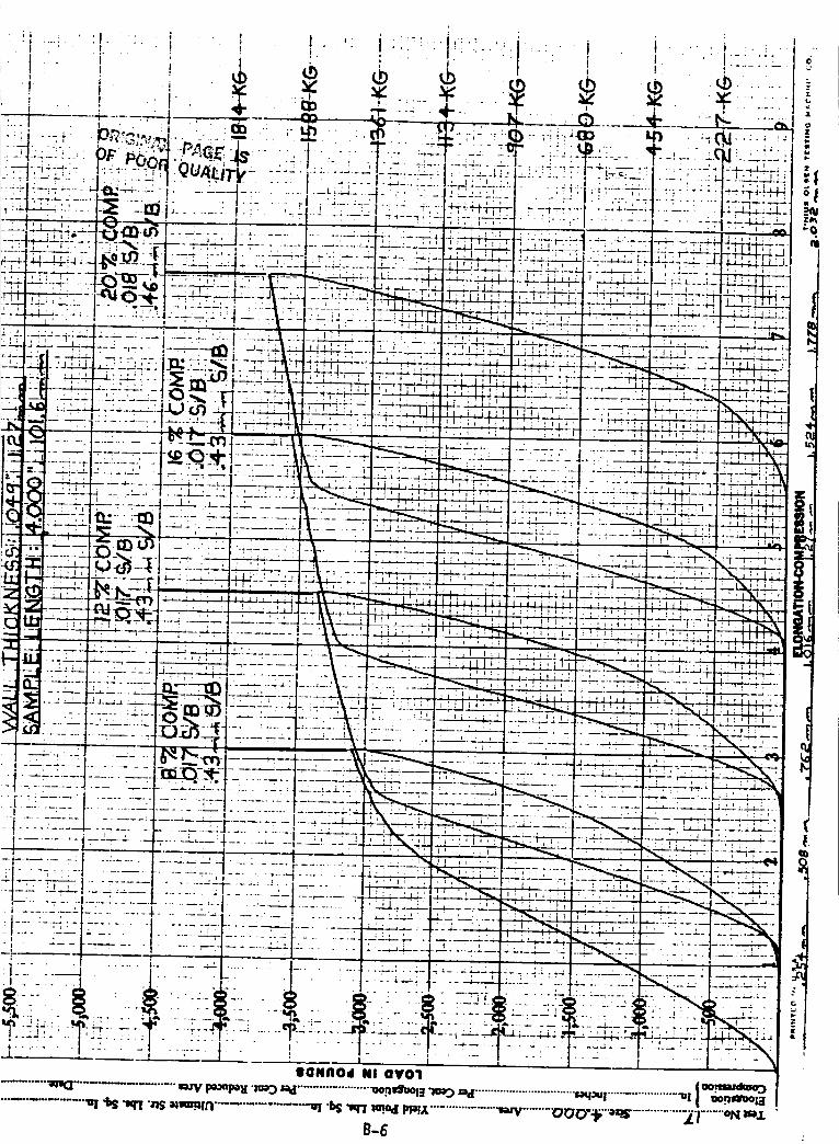
: i-" ',-, ,
I
i i ' • • '
- i
............I---!
: r
' I
! :
II
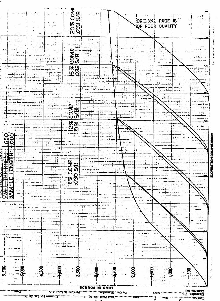
..... t
n
_!
iI
!
I
I
i
_I--I ', _i....-_ - : ........ ,'- :- ,"--"i--1 I ::'" a
............... j; .......... I1 .............. t ..................................... i .......
i--_;_-L;::_I_-;_:_.-_z___--:_::_- _-_" - ......i v . .,...... :---: :- ' .....I...... _]
, ......... - .... :4-- -:---_-:...... q- ....._-_- .---=------:G.........,...... ::--:: -:---.....::I -; ..... -I .... --L--m....... 1--_ ...... t-_- "-1...... -.... 1..... : ,, "F ....- ------K: .....--z-----:i---_:----I.....:_I-:---_-:--::: .........
.::!-..-::... :::_:__!_!::L-.I.:.:.__3-... i:. :--I-:-.-:-I- " :-i .' .1 _...,- .- , , ,_ ......--....... .. • .... , _.:-1-!--i :-:;;I-::-i;-:!--_:-:_::;:'::- I:- _, ..... ;::!:: -;.
........ ' " " I ...... = ...... I .... _ ...... 1"- -7-- _ " -
i =!. -, : :-!tL:;;::.-: _" --l :: 1 ,-: :--:I " I:;::......... --"
.= i - - I ----.._,. "IIONi'lOd NI QV01 !
.............. _ "_ ",_ "_ ,,,_. _r_................. _ "_ _rx_ _,,_....................._ ............;[:/;.......-:s............._"............o_=,._
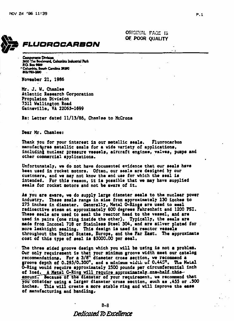
HOV ;=4 '86 11:39 P.1
FLUDI:IOOAI:IBON• i L
Comps,wanDVd,_a_11.lJm,bva_Cehm_ladueradl_rki_(_ lknt980e
oCoIu,n_ So_ _ WaOeoo/78).:lMO
Novaber 21, 1986
O._!G:_r_L FAGE iS,POOR QUALITY
P_r. J. W. Chamlee
Atlantic Research Corporation
Propulsion Division7511Welltniton RoadGaineville, VA 22065-1699
Re: L, tter dated 11/13/86, Ch,mlee to HcCroaa
i
Dear Kr..Chamlee=
Thank _ou for your interest In our mata111c seals. Fluorocarbonmanufac_res metallic seals for a vide variety of appllcstlons,Includln_ nuclear pressure vessels, aircraft enalnee, valves, pumps andother commercial applications.
Unfortunately. we do not have documented evidence that our seals havebeen used in rocket motors. Often, our seals are desiined by ourcustomers, and we may not know the end use for which the seal Isintended. For this reason, iC is possible that ve nay have suppliedseals for rocket motors and not be aware o! it.
As you are aware, we do supply lares diameter seals to the nuclear powerindustry. These seals ran8 • in size from approximately 130 inches to275 inches in diameter. Generally, Metal O-Rin8e are used to sealradioactive steam at spprozlmstely 600 deirees Fahrenheit and 1200 PSX.These seals are used to seal the reactor head ¢o the vessel, and are
used in pairs (one rln8 inside the other). Typlcally, the seals aremade from lace•el 718 or Stainless Steel 30_. and are silver plated for
more leakttBhc sea_tna. This desi8n is used in reactor vesselsthrouihout the United States, Europe, and the Far East. The approximatecost of thAs type of seal is $5000.00 per seal.
The three aided 8reeve desian which youwAll be uein8 is not • problem.
Our only requirement is that your minimum 8roove _rLdth meet our catalo8recomendations. For a 3/8" diameter cross section, _ recommend a
8roove depth of 0.2_5/0.$00", and a minlamm vAd_, vf 0.&45". The Mel.alO-Rins would require approximately 2500pounds per circumferential inchof 1sepal C-RinlVill require a_DroxlmJt_?y nn*-half tk_4m_amoun.c_'-_Bocsu_e O! the dAsaeter o! your'requireaent, we reconmnd Chat
7ou_sider usln8 a lar8er diameter cross section, such as .455 or .500inches. ThAn wall create 8 more stable rim8 and will improve the ease
of nanufacturin8 and handlin8..
• B-8
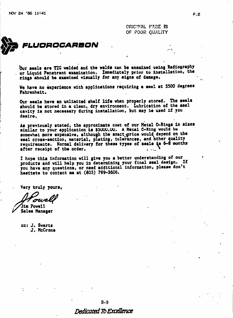
NOV 24 'e6 11:41 P.2
FLUDNOCANmON
OREC_%!AL P._GE IS
OF POOR QUALITY
"Our seals ere TIGwnlded and the velds can be oxeELned ustnaRadtoEraphy
- or L.tqutd Penetrant exantnation. I_edltcely prior to tnstalla_ton, thertn8s should be exeuinad visually for any siena of dana8 e,
We have no experience w_ch applications r6qutrtn8 • seal at 5S00 dearees
Fahrenheit.
Our seals have sn unl_Lted shelf life vhen properly stored. The sealsshould be scored in 8 clean, dry environment. Lubrication of the seal
cavlty is not necessary durtnE £nstalletion, but nay be used t_ youdesire.
As previously stated, the approximate cost of our Metal O-Rinse in sizessimilar to your application ls $_JYJ._. A Ne:aI _-Rln8 would bwsomevhat more expensive, althouah the exact__rtce voul_depend on theseal cross-section, materiel, platens, toleranceej sndbther quality
requireunts. Normal delivery for these types o£ |eels _ 6-8 monchaafter receipt of the order. ....
I hope chts tn£ormatton will 81ve you a better underetandtn8 of ourproducts and will help you in determinin8 your final seal destan. Ifyou have any questions, or need additional information, please dantehesitate to contact ne st (803) 799-3606.
t
Very truly yours,
na8er
CO: J. SwartzJ. _cCrone
B-9
FLUOROCARBONMetallic Gasket Division
P.O. Box 156.%9
Houston, Texas _'220
7|3145B-5830 Fax 713/458-0502 Telex 762-79|
US 1-800-972-7638 Texas 1-800.83_-0176
November 20 • 1986
Mr. J. W. Chamlee
Program Manager
Space Shuttle SRMAtlantic Research Corporation
Propulsion Division
7511 Wellington RoadGainesville, Virginia 22065-1699
Dear Mr. Chamlee :
After carefully reviewing your correspondence of
13 Novmeber 1986 we are declining the opportunity to
participate in the redesign of the seal for the SRM
joint in question.
We manufacture to our customer's design and American
Petroleum Institute Standards but do not have the re-
sources available to respond to your requests.
Sales and Marketing ManagerFluorocarbon Metallic Gasket Division
MB/vac
B-10
Dedicated To Excellence
FLUOROCARBON
OR!G_?,!,_LPAGE I'3
OF POOR QUALITY
METALLIC Q-RING8
; °
B-11
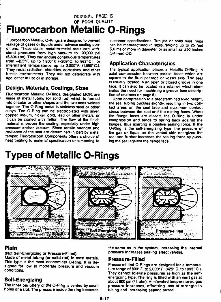
OF POOR QUALITY
Fluorocarbon Metallic O-RingsFluorocarbon Metallic O-Rings are designed to preventleakage of gases or liquids under adverse sealing con-ditions. These static, metal-to-metal seals can with-
stand pressures from high vacuum to 100,000 psi(6,804 atm). They can endure continuous temperaturesfrom -425 ° F. up to 1,800 ° F. (-269 ° C. to 982 ° C.), orintermittent temperatures up to 3,000°F. (1,650°C.).They-resist radiation, chlorides, corrosives, and otherhostile environments. They will not deteriorate withage, either in use or in storage.
Design, Materials, Coatings, SizesFluorocarbon Metallic O-Rings, designated MOR, aremade of metal tubing (or solid rod) which is formedinto circular or other shapes and the two ends weldedtogether. The O-Ring metal is stainless steel or otheralloys. The O-Ring can be electroplated with silver,copper, indium, nickel, gold, lead or other metals, orit can be coated with Teflon. The flow of the finish
material improves the sealing, especially under highpressure and/or vacuum. Since tensile strength andresilience of the seal are determined in pert by metaltemper, Fluorobarbon Components offers a choice of
heat treating to material specification or tempering to
customer specifications. Tubular or solid wire ringscan be manufactured in sizes_ranging up to 25 feet(7,6 m) or more in diameter, Or as small as 250 inches(6,4 mm) OD.
Application CharacteristicsThe typical application places a Metallic O-Ring inaxial compression between parallel faces which aresquare to the fluid passage or vessel axis. The sealis usually located in an open or closed groove in oneface. It can also be located in a retainer, which elim-
inates the need for machining a groove (see descrip-tion of retainers on page 8).
Upon compression to a predetermined fixed height,the seal tubing buckles slightly, resulting in two con-tact areas on the seal face and maximum contact
stress between the seal and the mating faces. Whenthe flange faces are closed, the O-Ring is undercompression and tends to spring back against theflanges, thus exerting a positive sealing force. If theO-Ring is the self-energizing type, the pressure ofthe gas or liquid on the vented side energizes theseal and further increases the sealing force by push-ing the seal against the flange face.
Types of Metallic O-Rings
Plain(Not Self-Energizing or Pressure-Filled)Made of metal tubing (or solid rod) in most metals.
This type is the most economical O-Ring. It is de-signed for low to moderate pressure and vacuumconditions.
Self-EnergizingThe inner periphery of the O-Ring is vented by smallholes or a slot. The pressure inside the ring becomes
the same as in the system. Increasing the internalpressure increases sealing effectiveness.
Pressure-FilledPressure-filled O-Rings are designed for a tempera-ture range of 800" F. to 2,000" F. (425" C. to 1093" C.).They cannot tolerate pressures as high as the self-energizing type. The ring is filled with an inert gas atabout 600 psi (41 atm). At elevated temperatures, gaspressure increases, offsetting loss of strength intubing and increasing sealing stress.
B-12
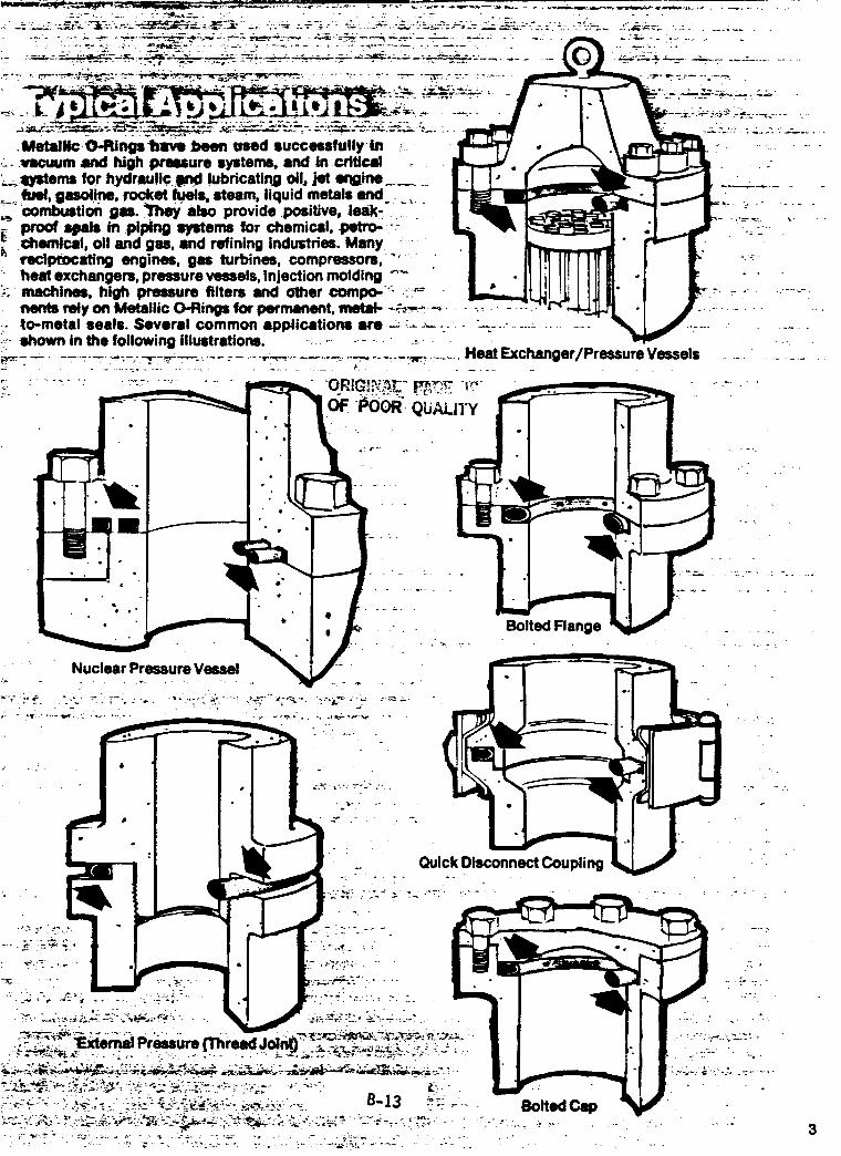
• +
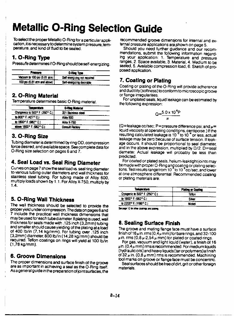
Metallic O-Ring Selection GuideTosekct the proper Metallic O-Ring for a particular appli-cation, itisnecessary to determine system pressure, tem-perature, and kind of fluid to be sealed.
1. O-Ring TypePressure determines ifO-Ring should be self-energizing.
IPmum 0-1_0TmVacuum to 100 psi (6.81 aim) S_f-ene_izing not _luired
100 psi (6.81 arm and above) Set1-eneRizing (lesirable
2. O-Ring MaterialTemperature determines basic O-Ring material.
Tmmnmmt 04_ =amr_OWOmCsto500° F.(260° C.) 321_inlesssteelto800° F.(427° C.) AllOy600tO1800° F.(g82° C.) Alk_)(-750ab0m1800° F.(982° C.) COnSUlt
3. O-Ring SizeTubing diameter isdetermined by ring OD, compressionforce desired, and available space. See complete data forO-Ring size selection on pages 6 and 7.
4. Seal Load vs. Seal Ring DiameterCurves on page 7 show the seal load vs.seal ring diameterto various tubing outer diameters and wall thickness forstainless steel tubing. For tubing made of Alloy 600,multiply loads shown by 1.1. For AlloyX-750, multiply by1.4.
5. O-Ring Wall ThicknessThe wall thickness should be selected to provide theproper yield under compression. The data on pages 6 and7 include the practical wall thickness dimensions thatmay be used for each tube diameter. If plating isused, wallthickness for seals made with. 125 inch (3,2ram) tubingand smaller should cause yieldingof the plating at a loadof 400 Ib/in (7,14 kg/mm). For tubing over .125 inch(3,2ram) diameter, 800 Ib/in [14,28 kg/mm) should berequired. Teflon coatings on rings will yield at 100 Ib/in(1,78 kg/mm}.
6. Groove DimensionsThe proper dimensions and surface finish of the grooveare as important in achieving a seal as the O-Ring itself.As a general guide inthe preparation of jointsurfaces, the
recommended groove dimen_ons for internal and ex-ternal pressure applications are_shownon page 5.
Should you need further guidance and our recom-mendations, submit the following information regard-ing your application: 1. Temperature and pressureranges, 2. Space available, 3. Material, 4. Medium to besealed, 5. Available compression load, 6. Sketch of pro-posed application.
7. Coating or PlatingCoating or plating of the O-Ring will provide adherenceand ductility (softness_to conform to microscopic grooveor flange irregularities.
FOr unplated seals, liquid leakage can be estimated bythe following expression:
Q=5.0 x 10eP
(O=leakage cc/sec; P=pressure difference psi; and _=liquid viscosityat operating conditigns, centipoise.) If theresulting calculated leakage is 10+ to 10" or less, actualleakage may be zero because of surface tension. If leak-age occurs, it should be proportional to seal diameter,and in the above expression, multiplied by D/2. D=sealdiameter. Actual leakage will probaDly be less thanpredicted.
For coated or plated seals, helium-leaktight joints maybe made with proper O-Ring an_ coating or plating selec-tions. Testresults range from 10_ to 10-* cc/sec, and lowerat one atmosphere differential. Recommended coatingor plating materials are:
Tmlnml I'1=_ =cuilCr_genicto500° F (260° C.) Tetbnto1800° F.(982° C.) Siketo 2200 ° E (1186 ° C.) Nickel
_e paOe12I= ob'wcoamOsandpmmo
8. Sealing Surface RnishThe groove and mating flange face must have a surfacefinishof 16_in. rms(0,4_mm)for bare rings, and 32-100
in. rms (0,8 _-2,54 _ mm) for plated or coated rings.For gas, vacuum and light liquid (water), a finish of 16
in. [0,4 # ram) rms is recommended. For mediu m liquids(hydraulic oils) and heavy liquids {tar or polymers) a finisho! 32 # in. [0,8 # mm} rms is recommended. Machiningtool marks on groove or flange face must be concentric.
Seal surfaces should be free of dirt, grit or other foreignmaterials.
B-24
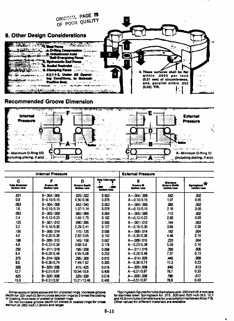
9. Other Design Considerations
S.These surfaces shall be flat ---within .000S per inch ....(0,01 ram) of circumference, ..lind, plirmllel within .002(o,os) TIR.
J- ......t
Recommended Groove Dimension
.: F E,, Intml "_ _- __ I--_" "::_ Extemlll
j.._ l _ " _ -- .." " 'x _ " " '_-
Internal Pressure External Pmuum
C F D =_ _rmr=,_ E ,,-_m.TIN Ilim IrNve i IrN_e _ " " lrN_l I Imve Wa _ _
k_hOl/ml k_Jmllnn k_kos/nm *l -.Ill k_N/N Im=kos/nm Ii_kel/mmk_ms/auNn
.0310,8.0631,6
.0932,4
.1253,2.1504,0
.1884,8
2506,43759.5
.50012,7
.62515,9
B+.O04/.006B+0,10/0,15B*.004/.006B+0,10/0,15B+.005/.009B÷0,13/0.23
B*.007/.012B*0,18/0,30B*.008/.014B*0,20/0,36B*.009/.015B+0,23/0,38B..011/.019B+0,28/0,48B..014/.029B+0,36/0,74
B÷.020/.038B÷0,51/0,97B+O20/.038B+0,5110,97
.020/.0220,5010,56
.0421.0451,07/1,14.065/.0691,651135.O9O/.O952,29/2,41.115/.1202,92/3,05.145/.1503,68/3,8.1951.2004,95/5,08295/.3OO7,49/7,62.415/.425
10,54/10,8
.52O/.53O13,21/13,46
0.0030,076
0.0030,0760.0040,1020.0050,127
0.0060,15200070,17800080,2030.0120,3050.0160,406
0.0160,406
A--.004/.006A--0,10/0,15
A--.004/.006A--0,10/0,15A--.005/.009A--0,13/0,23A--.007/.012A--0,18/0,30A--.008/.014A--0,30/0,36A--.009/.015A--0,2310,38A--.011/.019A--0,2810,48
A--.014/.I_9A--0,3610,74A--.020/.038A--0,51/0,97A--.020/.03_A--0,51/0,97
.0421,07
.0852,16.1122,80.1443,68.1824,462205,59.2907,37.44511,3
.64516,7.78019.8
.OO20,05
.0020,05.0020,05.0030,08.0040,10
.0040,10
.0050,13
.0090,23.0130,33
.0170,43
Dimensionsintable abo_ am for unplatadrings.Increase9roo_depth for .031 inch(O,Smm)crosssectionringsby2 timestheplatintlor coatingthicknessof plated orcoated rings.
Do not increasegroovedepth on platedor coated ringsfor croessectionof .063 inch( 1,6ram)lind larger.
*Springbeckfiguresfortubediametersupto .250 inch(6,4 mm)tireforstainlesssteel. Springbackfor .375, .500 lind .625 inch(9,5, 12,7lind15,9 mm)tubediametersam forprecipitationhardenedAlloy718.Othervalues for differentmliteriliIsareavailable.
B-15
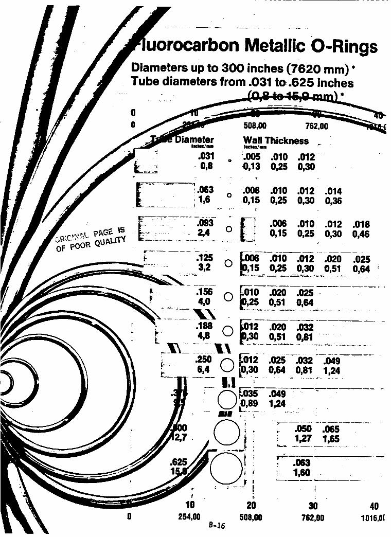
0
Metallic O-Rings
0
0 508,00 762,00
ler Wall ThicknessIK'bls/mm IRkes/mm _'_
•, .031 o !.005 .010 .012-___ 0,8 0,13 0,25 0,30
.010 .012 .0140,25 0,30 0,36
.006 .010 .012 .0180,15 0,25 0,30 0,46
.010 .012 .020 .0250,25 0,30 0,51 0,64
4O
1016,0(
Diameters up to 300 inches (7620 mm) *Tube diameters from .031 to.625 inches
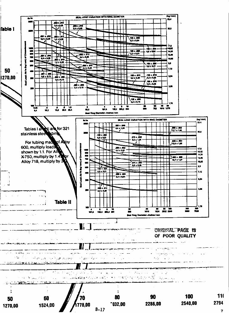
Fable I
5O
270,00
li#1m
Tables I for 321
stainless ste i
For tubing
600, multiply Ioa¢shown by 1.1. For AI
X-750, multiply by 1.,
Alloy 718, multiply by
50 60 70 80 90 100
1270,00 1524,00 ,00 "032,00 2286,00 2540,00B-17
1112794
7
.... " -- ...... -_"-.. '_ft.T_'TAL_--PA_-E IS
. . . _ . _-. OF POOR QUALITY
" .L:: 21I._-J_._.____............, .- .+ . . , . .
. -..__ : _.- ,.. _ ;_ .-_:.--.- .._ . ._:-. -; .... ....... . • -._ ,
i I
• --" : _,.- " ":: -. " : . -- • . _. -A,:!:M _,k""._'.. ,..'. -' - ... - '
',_ ,_,-it=r,;, ,%'._._: 2.:I,:-::_:..--_'_-- -_ -. -_-._._.... _,, - . ._--_--_-....-._,- ,. ..-__.... _ . ;.....................
.::_L:......-.-Lll]
Table II1,111
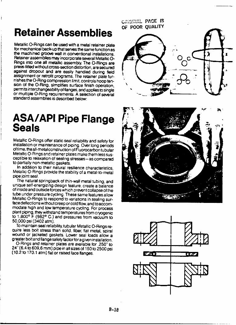
Retainer AssembliesMetallic O-Rings can be used with a metal retainer platefor mechanical beck-up that serves the same function asthe machined groove wall in conventional installations.Retainer assemblies may incorporate several Metallic O-Rings into one all metallic assembly. The O-Rings arepress-fitted without cross-section distortion, are securedagainst dropout and are easily handled during fieldassignment or retrofit programs. The retainer plate fur-nishes the O-Ring compression limit,controls hoop ten-sion of the O-Ring, simplifies surface finish operation,permits interchangeability of flanges, and applies to singleor multiple O-Ring requirements. A selection of severalstandard assemblies is described below:
ASA/APi Pipe FlangeSealsMetallic O-Rings offer static seal reliability and safety forinstallation or maintenance of piping. Over long periodsof time, the all-metal construction of Fluorocarbon tubularMetallic O-Rings and retainer plates make them less sus-ceptible to relaxation of sealing stresses-as comparedto partially non-metallic gaskets.
In addition to their natural resilience characteristics,Metallic O-Rings pr_-ide the stability of a metal-to-metalpipe joint seal.
The natural springback of thin-wall metal tubing, andunique self-energizing design feature, create a balanceof inside and outside forces which prevent collapse of thetube under pressure cycling. These same features allowMetallic O-Rings to respond to variations in sealing sur-face deflections without creep or cold flow, and toaccom-modate high and low temperature cycling. For processplant piping, they withstand temperatures from cryogenicto 1,800 ° E C982° C.) and pressures from vacuum to50,000 psi (3402 atm).
To maintain seal reliability, tubular Metallic O-Rings re-quire less bolt stress than solid, fiber, flat metal, spiralwound or jacketed gaskets. Lower seal loads allow agreater bolt and flange safety factor for agiven installation.
O-Rings and retainer plates are available for .250" to24" C6,4to 609,6 ram) pipe in all sizes of 150 to 2500 psiC10.2to 170.1 atm) flat or raised face flanges.
•-,'-,'",',": PAGE IS
OF POOR qUALITY
%
B-18
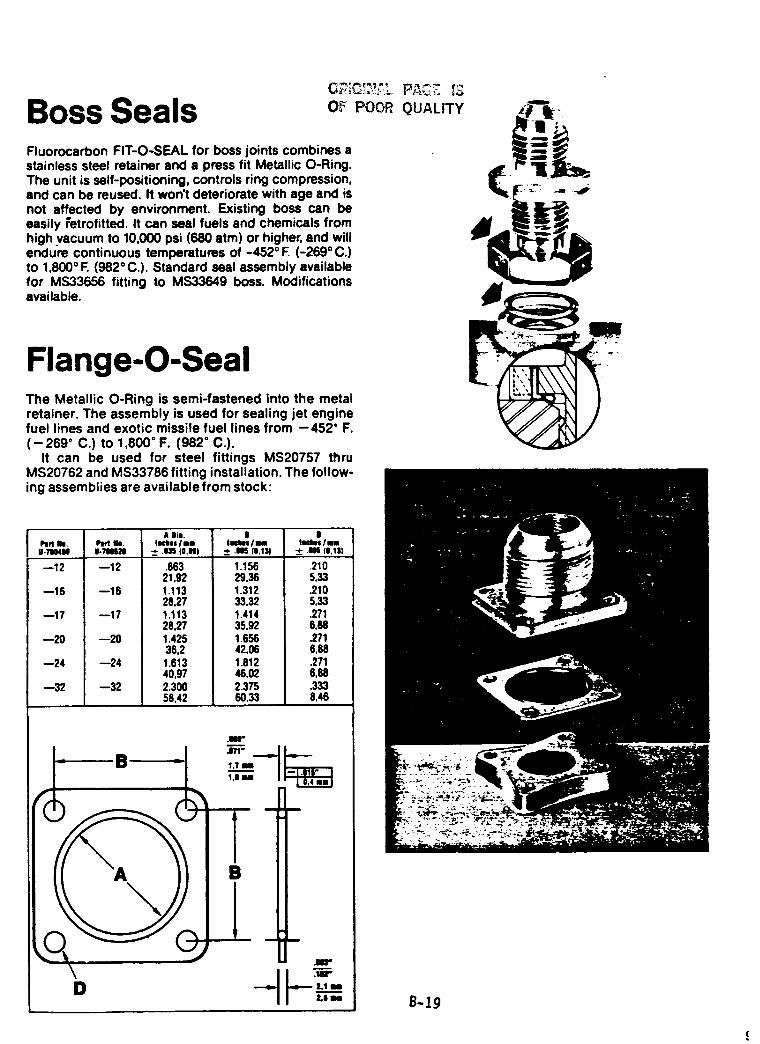
Boss Seals OF POOR
Fluorocarbon FIT-O-SEAL for boss joints combines astainless steel retainer and a press fit Metallic O-Ring.The unit is self-positioning, controls ring compression,and can be mused. It won't deteriorate with age and isnot affected by environment. Existing boss can beeasily _'etrofitted. It can seal fuels and chemicals fromhigh vacuum to 10,000 psi (680 atm) or higher, and willendure continuous temperatures of -452 ° E (-269 ° C.)to 1,800 ° F. (982 = C.). Standard seal assembly available
for MS33656 fitting to MS33649 boss. Modificationsavailable.
QUALITY
Flange-O-SealThe Metallic O-Ring is semi-fastened into the metalretainer. The assembly is used for sealing jet enginefuel lines and exotic missile fuel lines from --452" F.
(--269 ° C.) to 1,800 ° F. (982 ° C.).It can be used for steel fittings MS20757 thru
MS20762 and MS33786 fitting installation. The follow-
ing assemblies are available from stock:
--12
--16
--17
--20
--24
--32
--12
--16
--17
--20
--24
--32
A Ill.
Im_os I nI
-_- .Ul (0,NI
.863 1.15621,92 29.361.113 1.31228,27 33,321.113 1.41428,27 35,921.425 1.65636,2 42,061.613 1.81240,97 46,022.3OO 2.37556,42 60,33
I I
lUNIIII II¢lHII/N
± .I l|.ll) ± .I (0.II)
.2105,33.2105,33.2718.88.2716,88.2716,88.3338,46
.I"
.171" -.---on,
I.? N
1,11 II
m.
a m i
B
m i i
i ="_ 1.111
ILl U B-19
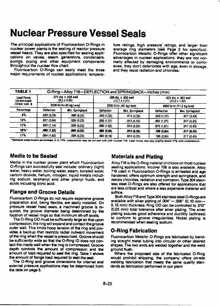
Nuclear Pressure Vessel SealsThe principal applications of Fluorocarbon O-Rings innuclear power plants is the sealing of reactor pressurevessel heads. They are also specified for sealing appli-cations on valves, steam generators, condensers,
puml_s, piping and other equipment componentsthroughout the nuclear flow chert.
Fluorocarbon O-Rings can easily meet the threemajor requirements of nuclear applications: tempera-
ture ratings, high pressure-ratings, and larger thanaverage ring diameters (._ Page 2 for specifics).
Fluorocarbon Metallic O-Rings offer other significantadvantages in nuclear applications: they are not nor-mally affected by damaging environments or corro-
sives; they don't deteriorate with age, even in storage,and they resist radiation and chlorides.
TABLE 1 O-Ring--Alloy 718--DEFLECTION and SPRINGBACK--Inches (mm)
LoadForceUnrestrained
/linearinch t
Percentage
.375dia.x .038wall(9,5 x 0,95)
2500 Ib/in (45kg/mm)Deflection Min.Spdngback
.SO()dia.x .050wall(12,7x 1,27)
2500Ib/in (45 kg/mm)
Deflection Min.Springback
.625dia.X.063wall(15,9x 1,60)
4000Ib/in (71.5kg/mm)
Deflection Min.Springback
8% .030(0,76) .009(0,23) .040(I,02) .013(0,33) .050 (1,27) .017 (0,43)
10% .037 (0,94) .009(0,23) .050 (1,27) .013(0,33) .062(1,57) .017 (0,43)
12% .045 (1,14) .009(0,23) .060(1,52) .013 (0,33) .075(1,91) .017 (0,43)
11%" .010 (1,12)
17% .064 (1,63)(0,23) JII0 (2,03) .113 (0,33) .1W (2,64) .017 (0,4,1)
.009(0,23) .085(2,16) .013 (0,33) .106(2,69) .017 (0.43)• Op(/mum ¢ompree_ IJerceMafe. 8 to 17% compression may be utihze¢l with UAP Inco_el 7t#. Load tortes may varf Ilighfly below 17% inch comDrelsion.
Media to be Sealed
Media in the nuclear power plant which Fluorocarbon
O-Rings can successfully seal include: ordinary (light)water, heavy water, boiling water, steam, borated water,carbon dioxide, helium, nitrogen, liquid metals includ-
ing sodium, terphenyl and other phenyl fluids, andacids including boric acid.
Flange and Groove DetailsFluorocarbon O-Rings do not require expensive groovepreparation and, being flexible, are easily installed. Onpressure vessel head seals, a machined groove is re-quired, the groove diameter being determined by thelocation of vessel rings so that minimum lift-off exists.
The O-Ring OD must be sufficiently large so that uponcompression, the ring will expand and contact the grooveouter wall. This limits hoop tension of the ring and pro-rides a backup that restricts radial outward movementof the ring when the vessel is pressurized. Groove shouldbe sufficiently wide so that the O-Ring ID does not con-tact the inside wall when the ring is compressed. Groovedepth controls the amount of compression and theamount of load required to seat the ring. Table 1 showsthe amount of flange load required to seat the seal.
The O-Ring and groove dimensions for internal andexternal pressure applications may be determined fromthe data on page 5.
Materials and PlatingAlloy 718 is the O-Ring material of choice on most nuclearsealing applications. Inconel 706 is also available. Alloy
718 used in Fluorocarbon O-Rings is annealed and agehardened, offers optimum strength and springback, andresists chlorides, radiation and corrosion. Type 304 stain-less steel O-Rings are also offered for applications thatare less critical and where a less expensive material willsuffice.
Both Alloy718 and Type 304 stainless steel O-Rings areavailable with silver plating of .004"--.006" (0, 10 mm--O, 15 mm) thickness. Ring OD can be controlled to .010"
(025 ram) total tolerance after silver plating. The silverplating assures good adherence and ductility (softness)to conform to groove irregularities. Nickel plating isrecommended when sealing sodium.
O-Ring FabricationFluorocarbon Metallic O-Rings are fabricated by bend-ing straight metal tubing into circular or other desired
shapes. The two ends are welded together and the weldground flush.
Where the proposed size of the fabricated O-Ringwould prohibit shipping, the company offers on-site
welding fabrication that meets the same quality stan-dards as fabrication performed in our plant.
e-20
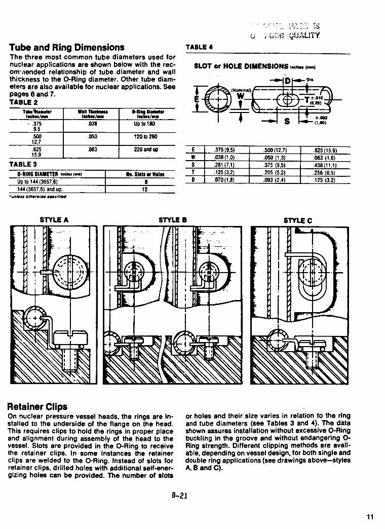
Tube and Ring DimensionsThe three most common tube diameters used fornuclear applications are shown below with the rec-om',lended relationship of tube diameter and wallthickness to the O-Ring diameter. Other tube diam-eters are also available for nuclear applications. Seepages 6 and 7.TABLE 2
Tulmall_meter Well b O-IIIq DiamehlcIn_'hes/mm Ilcllqos/nm Im¢lnos/mn
- .375 .038 Up 101809.5.500 .050 120 to 26012,7
.063 220 and up.62515.9
TABLE 3
O-RING DIAMETER ORM, (=,.) NO. SlOts or Helel
Up to 144 (3657,6) 8
144 (3657,6) and up. 12
*unless otherwisB 8pecifl_l
TABLE 4
SLOT or HOLE DIMENSIONS ,._m (ram)
•_mm,,_i _ Die.
"_d_. (Nomlnld) _
E .375 (9,5)
W .038 (1,0)
S .281 (7,1)
T .125 (3,2)
D .070 (1,8)
.500 {12,7) .625 (15.9)
.050 (1,3) .063 (1,6)
.375 (9,5) .438 (11,1)
.205 (5,2) .256 (6,5)
.093 (2,4) .125 (3,2)
t: i
L
r
i- I
"lk'_ '
R,_ "%
STYLE A STYLE B STYLE C
Retainer ClipsOn nuclear pressure vessel heads, the rings are in-stalled to the underside of the flange on the head.This requires clips to hold the rings in proper placeand alignment during assembly of the head to thevessel. Slots are provided in the O-Ring to receivethe retainer clips. In some instances the retainerclips are welded to the O-Ring. Instead of slots forretainer clips, drilled holes with additional self-ener-gizing holes can be provided. The number of slots
or holes and their size varies in relation to the ringand tube diameters (see Tables 3 and 4). The datashown assures installation without excessive O-Ringbuckling in the groove and without endangering O-Ring strength. Different clipping methods are avail-able, depending on vessel design, for both single anddouble ring applications (see drawings above--stylesA, B and C).
B-21
11
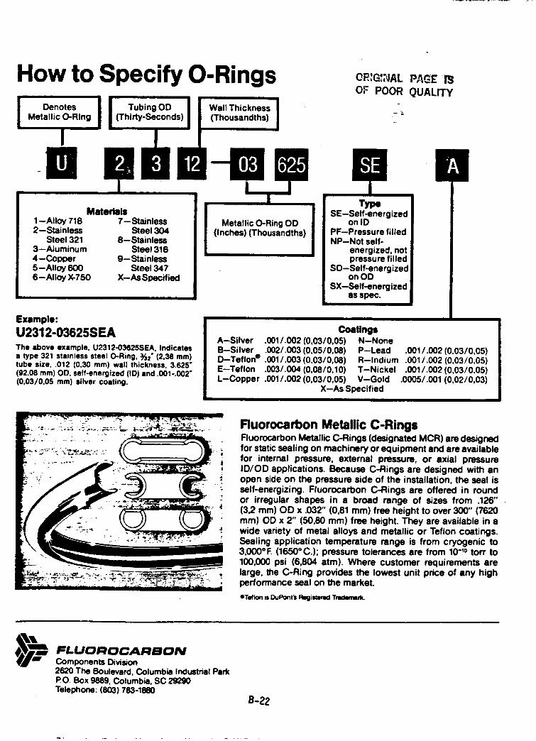
How to Specify O-Ringsii
Metallic O-Ring (Thirty-Seconds) (Thousandths)
! •OR,G=NALOF POOR
PAGE' '1_
QUALITY
Materials1--Alloy 718 7-- Stainless2--Stainless Steel 304
Steel 321 8--stainless3--Aluminum Steel 3164--CopDer 9--stainless5--Alloy 600 Steel 3476--Alloy X-750 X--As Specified
Example:
U2312-03625SEA
The above example, U2312-03625SEA, Indicatesa type 321 stainless steel O-Ring, "_2"(2,38 mm)tube size, .012 (0,30 mm) wall thickness, 3.625"(92,08 ram) OD, self-energized (ID) and .001-.002"(0,03/0,05 ram) silver coating.
Metallic O-Ring OD(Inches) (Thousandths)
TypeSE--Self-energized
on IDPF--Pressure filledNP--Not self-
energized, notpressure filled
SO--Self-energizedon OD
SX--Self-energizedas spec.
Coatings
A--Silver .0011.002 (0,03/0,05) N--NoneB--Silver .002/.003 (0,05/0,08) P--LeadD--Teflon e .0011.003 (0,03/0,08) R--IndiumE--Teflon .0031.004 (0,0810,10) T--NickelL-Copper .0011.002 (0,0310,05) V--Gold
X--As Specified
.001/.002 (0,03/0,05)•001 i.002 (0,03/0,05)•0011.002 (0,03/0,05)
.0005/.001 (0,02/0,03)
Fluorocarbon Metallic C-RingsFluorocarbon Metallic C-Rings (designated MCR) are designedfor static sealing on machinery or equipment and are availablefor internal pressure, external pressure, or axial pressureID/OD applications. Because C-Rings are designed with anopen side on the pressure side of the installation, the seal isself-energizing. Fluorocarbon C-Rings are offered in roundor irregular shapes in a broad range of sizes from .126"(32 mm) OD x .032" (0,81 mm) free height to over 300" (7620mm) OD x 2" (50,80 mm) free height. They are available in awide variety of metal alloys and metallic or Teflon coatings.Sealing application temperature range is from cryogenic to3,0000F. (1650°C.); pressure tolerances are from 10-'0 tort to
100,000 psi (6,804 atm). Where customer requirements arelarge, the C-Ring provides the lowest unit price of any highperformance seal on the market.
eTeflonisDuPont_RegimrKITnKlema_.
FLUOROCARBONComponents Division2620 The Boulevard, Columbia Industrial ParkPO. Box 9889, Columbia, SC 29290Telephone: (803) 783<880
B-22
ORI_NAL PAGE IS
O,¢ POOR QUALITY
FLUOROCARBON
METALLIC C-RINGS
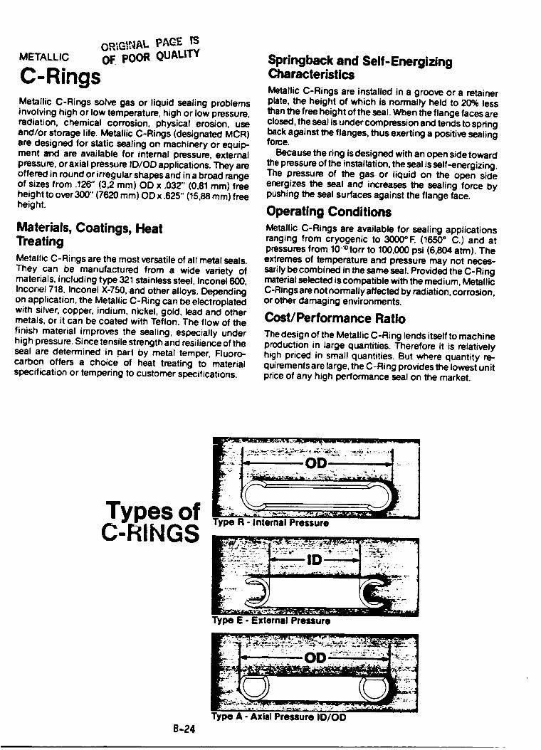
ORIG_,NA L p,_,GF- IS
METALLIC OF. pOOR QUALITY
C-RingsMetallic C-Rings solve gas or liquid sealing problems
involving high or low temperature, high or low pressure,radiation, chemical corrosion, physical erosion, use
and/or storage life. Metallic C-Rings (designated MCR)are designed for static sealing on machinery or equip-ment and are available for internal pressure, externalpressure, or axial pressure ID/OD applications. They areoffered in round or irregular shapes and in a broad rangeof sizes from .126" (3,2 ram) OD x .032" (0,81 mm) freeheight to over 300" (7620 ram) OD x .625" (15,88 mm) freeheight.
Materials, Coatings, HeatTreatingMetallic C-Rings are the most versatile of all metal seals.They can be manufactured from a wide variety ofmaterials, including type 321 stainless steel, Incone1600,Inconel 718, Inconel X-750, and other alloys. Dependingon application, the Metallic C-Ring can be electroplatedwith silver, copper, indium, nickel, gold, lead and othermetals, or it can be coated with Teflon. The flow of the
finish material improves the sealing, especially underhigh pressure. Since tensile strength and resilience of theseal are determined in part by metal temper, Fluoro-carbon offers a choice of heat treating to materialspecification or tempering to customer specifications.
Springback and Self-EnergizingCharacteristics
Metallic C-Rings are installed in a groove or a retainerplate, the height of which is normally held to 20% lessthan the free height of the seal. When the flange faces areclosed, the seal is under compression and tends to springback against the flanges, thus exerting a positive sealingforce.
Because the ring is designed with an open side towardthe pressure of the installation, the seal is self-energizing.The pressure of the gas or liquid on the open side
energizes the seal and increases the sealing force bypushing the seal surfaces against the flange face.
Operating ConditionsMetallic C-Rings are available for sealing applicationsranging from cryogenic to 3000°F. (1650 ° C.) and atpressures from 10_torr to 100,000 psi (6,804 atm). Theextremes of temperature and pressure may not neces-sarily be combined in the same seal. Provided the C-Ringmaterial selected is compatible with the medium, MetallicC-Rings are not normally affected by radiation, corrosion,or other damaging environments.
Cost/Performance Ratio
The design of the Metallic C-Ring lends itself to machineproduction in large quantities. Therefore it is relativelyhigh priced in small quantities. But where quantity re-
quirements are large, the C-Ring provides the lowest unitprice of any high performance seal on the market.
Types ofC-RINGS
B-24
mli*'_"Wll= =ll'=_J=-"='_"_"_ __J"_ _ _ _ _'_---" ......... -I
Type R -Internal Pressure
Type E - External Pressure
Type A - Axial Pressure ID/OD
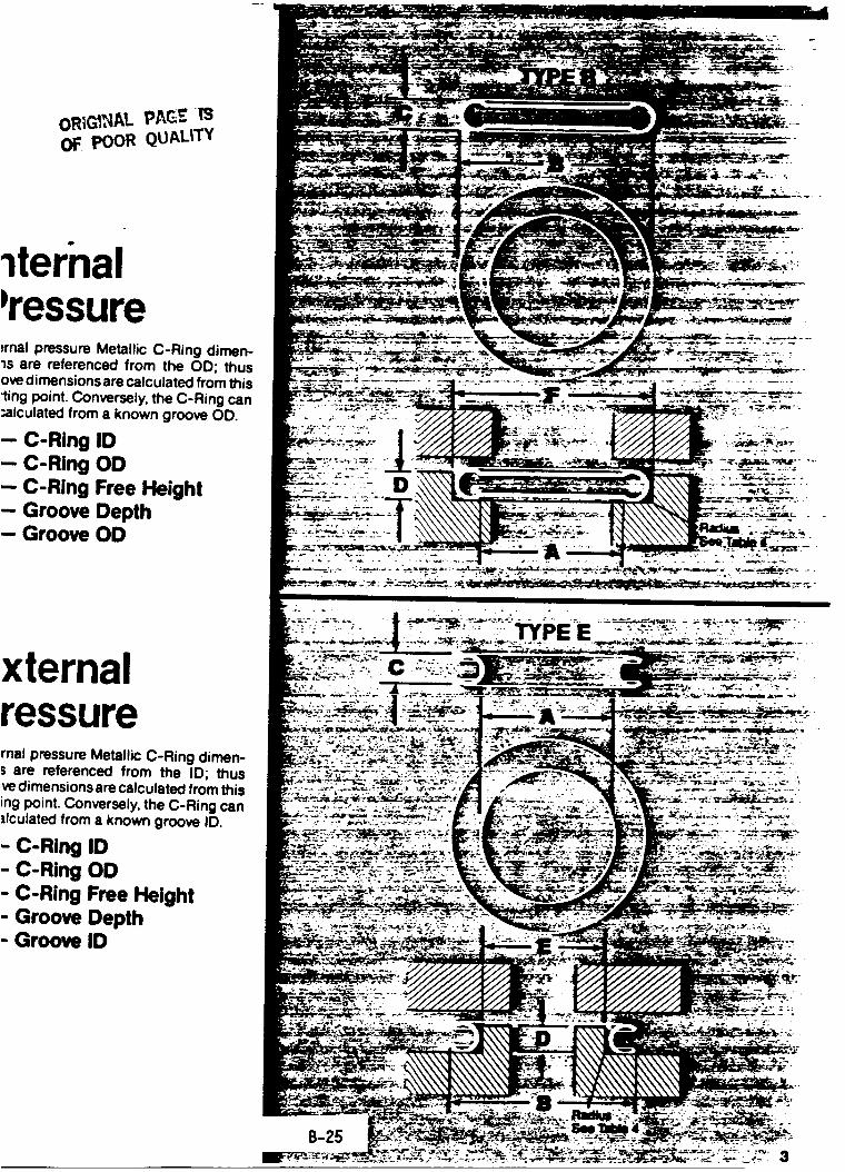
i
OF poOR QUALITY
temal ressure:rnal pressure Metallic C-Ring dimen-is are referenced from the OD; thusore dimensions are calculated from thisling point. Conversely, the C-Ring can:alculated from a known groove OD.
-- C-Ring ID-- C-Ring OD-- C-Ring Free Height- Groove Depth- Groove OD
xternalressurernal pressure Metallic C-Ring dimen-; are referenced from the ID; thus,vedimensions are calculated from thising point. Conversely, the C-Ring can ......... _"-_ ....._lculated from a known groove ID. _" ___"_.;;-_"_:" •
- C-Ring ID- C-Ring OD
- C-Rlng Free Helght- Groove Depth- Groove ID
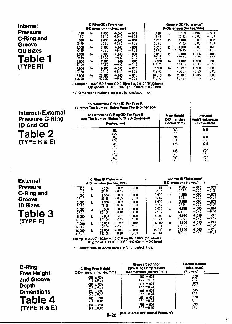
InternalPressureC-Ring andGrooveOD Sizes
Table) 1(TYPE
C-Ring DO/ToleranceIS-Dimension (Inches/ram)
.126 to 1.000 .1..000 -.00232 2540 +000 -005
1.000 to 2000 +.000 - 0022540 50 80 +0.00 -0 052.000 to 3.000 -4-.000 -.0035080 7620 4-000 -0083.000 to 5.000 -I-.000 --.0047620 12700 +0.00 -0.105.000 to 7.000 + .000 --.006
127.00 177.80 4-000 --0 157.000 to 16.000 ,1,.000 --.010
177 80 40640 +000 --0.2516.000 to 25.000 -t-.000 -O15406 40 635.00 +0.00 --0 33
Groove OD/Tolerance"F-Dimension (Inches/ram)
.135 to 1.010 +.002 - .0003 43 25 65 +0.05 -C:,_
1.010 to 2.010 +.003 -.00025.65 51,05 -- 00S - CO02.010 to 3.010 -I-.003 -.00051.05 - _" 76.45 +0 08 -0.003.010 to 5.010 +.004 --.0007645 !27.25 4-_ "O - C,._05.010 tO 7.010 +.006 --.000
127.25 178.05 +_ 15 -0037.010 tO 16.010 -t-.008 --.000
17805 4066,5 +020 --00016,010 tO 25.010 "1".015 --.0004_665 635.25 "_0 38 -0.C_
Example: 2.000" (50,8mm) OD C-Ring fits 2.010" (51,05mm)OD groove + .003"-.000" (+ 0,08ram - 0,00ram)
" F-Dimensions in above table are for unplated rings.
Internal/ExternalPressure C-RingID And OD
Table 2(TYPE R & E)
To Determine C-Ring ID For Type RSubtract The Number Below From The B-Dimension
To Determine C-Ring OD For Type EAdd The Number Below To The A-Dimension
(Inches/ram)
.1052 66.16043_2005O53007L_.400
Free HeightC-Dimension[Inches/ram)
.063
094
.126
1884_
252
StandardWall Thicknesses
(Inched/ram)
010
015
.015
o2or -,"
025
ExternalPressure
C-Ring andGrooveID Sizes
Table 3(TYPE E)
C-Ring I0/TolersnceA-Dimension (Inches/ram)
.126 1o 1.000 +.002 --.00032 2540 +005 -000
1.000 to 2.000 4-.002 --.00025 40 50 80 _-0 05 --0 O02.000 to 3.000 +.003 -.0005083 7620 +008 -0003.000 to 5.000 4-004 -- .00076 20 12700 4-0 10 -0 O05.000 to 7.000 +.006 -.000
127 O0 17780 +0 15 -C O07.000 to 16.000 4-.010 --.000
177 80 406 40 +025 -00_16.000 tO 25.000 4-.015 --.000
406 40 635 O0 +0 38 --0 00
Groove ID/Tolerance"E-Dimension (inches/ram)
.115 1o 0.990 +.000 -.0022._2 2;.£3 -_CC_ -CO. =
0.990 to 1.990 +.000 --.00325 14 5054 _0.03 -0 F,_1.990 tO 2990 4-.000 --.0035054 7594 -LOCO --0082.990 tO 4.990 .1..000 --.0047594 12(_74 +000 -0104.990 to 6.990 ,1,.000 --.006
12£.74 177.54 4-0 09 --0 156990 to 15.990 -t-.000 --.008
177 5-' -_.'_:14 +0 ,$3 --0 ."015.990 tO 25.990 .1..000 --.015406 14 6_0l_4 4-000 --03_
Example: 2.000" (50,Smm) ID C-Ring fits 1.990" (50,54mm)ID groove + .000" - .003" ( + 0,00mm - 0,08ram)
• E-Dimensions in above table are for unplated rings.
C-RingFree Heightand Groove
DepthDimensions
Table 4(TYPE R & E)
C-Ring Free HeightC-Dimension (Inches/ram)
.063 ±.00216 --005
.094 _.00224 _--0,05
.126 -'-.00332 __.0,08
.188 =.0044.8 ---0,10
.252 ¢.00464 ___0,10
B-26
Groove Depth for20% Ring Compression
D-Dimension (Inches/mm)
.050 _.001127 --0 03.074 -4-.0031.88 -_008.100 -_.0032.54 -_0 08.151 _.003
3.83 --0.08200 __..004508--010
For Internal or External Pressure)
Corner Radius(Maximum)
(Inches/ram)
.0200.50.030
0.76.0451.14.0701.77.090228
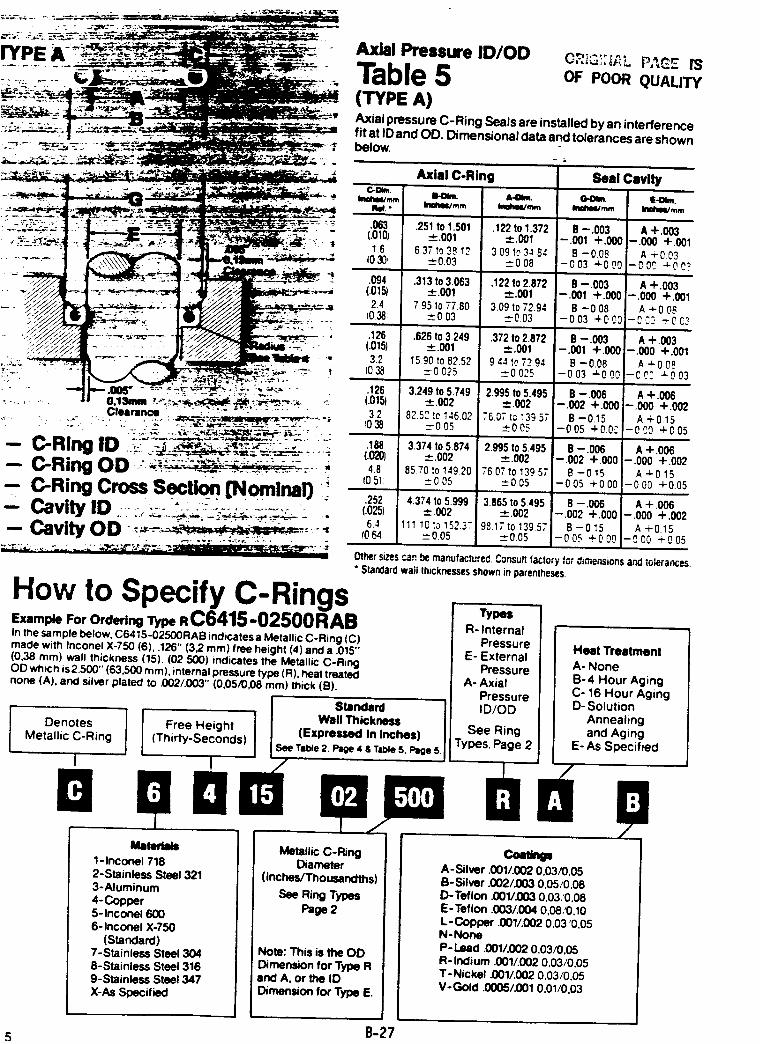
_,,_,.. :..;_--_.--_.x - Axial Pressure ID/OD O_2G:;_L PA_E m
::::._ Table 5 Poe.(WPEA)
__ _._'_."_' Axial pressure C-Ring Seals are installed by an interference
'_-:.I _ fitatlDandOD.Dirnensionaldataandtolerancesareshown.... ,-_=- =- ..... _,.____ _-T.,,=_- •z below.
_._._._.:-, "-_L_ :_._ _ '- _ ' _=_-':
•:_'----__-'_=_'_'_'_': -'-: : _ .063 .251 to 1301 ,122 to 1372 e -.003 ! & +.003
___.._.:.:_.,___...:_ (.o_o) _.ooi ±.oot -.oo_*.oooi-.ooo+.oot16 631to3812 309to3.=84 8-008 i A+003
..... _,,_..-_--____"4 io3o, _--003 ___008 -oo3_ooo -oo_ _oe?
. ,0,= =.oo, -oo,+.ooo-.o0o+.oo,.4-:.:"_:_ . .._;*.-_-- . ,._:.;_.. . (0.38: __003 _0.03 -003 +OOO)-C'..ID "rOe2,_/_ I _,_.,. ,. __ --: -: .,,; .6,8to32,9 I ,+.003
"_:;_ _7,_J ' ___ .-_'_'_-::_._., . (.015) _.001 -4-.001 --.001 +.000 --.000 +.001... _"_- /7 ......... •. ..:s-/ f'_2t -_/___'ilill_ ' 3.2 1590to82.52 944foT294 B -0.08 ] A +008
,..;;.:.."_"_-.- _ " _""',il__.:_,: .... ,_ (038 =0025 =0025 -003 '-'-OO01-CO.'2"=-003_. _-,".: y..,=-...... •: _ ;,.:_ _._-. _ ..
- o._'_,,,:--.:_;-__,_!_,_ ". (.o,_) _+.oo2 =oo2 -.oo_+.ooo_-.ooo+.oo2Clearance . _.._.-_._- -" - _ .... ;
_--. -: ,.-- .-: .... . ;,:. ': _,.. :__., .-.- .." : ..... : -. ,; _ .... £_-_._.,_,_--'e._-: _:,. _ . -
-- P-RIM II1 " --.__._'_:_,_/_-_":_':: -" '
C-Ring _u^" ....._.....'_'-"-:' "............... __ - ..
-- C-Ring Cross Sectk)n [Norninarj :':Cavity ID " .... " ..........I=, ..... , _:-- .-. ..... :':__;_ - ,,,
Pa, II, u r'_l"b
How to Specify C-RingsExample For Ordering Type R C6415-02500 RAB
In the sample below, C6415-02500RAB indicates a Metallic C-Ring (C)made with Inconel X-750 (6), .126" (3,2 ram) free height (4) and a .015"(0,38 ram) wall thickness (15). (02 500) indicates the Metallic C-RingOD which is2.500" (63,500 ram), internal pressure type (R), heat treatednone (A). and silver plated to .002/.003" (0,05/0,08 ram) thick (B).
DenotesMetallic C-Ring
32_038
.188(,0201
48(0 51:
.252(.025)
64(064
S_nds_d
82.5,. to t46.02_--005
3.374 to 5.874-,-.002
85 70 to 149.20:005
4.374 to 5.999-'-.002
111 10 to 152.3.-_-0.05
";6.07 tc!39 57_005
2.9951o 5.495-*-.002
76 071o 139 57-'-0 05
3.865 to 5.495-_.002
9&lT to 139.5";".."-0.05
B -0.15-0 05 +0.0C
B -.006-,002 +.000
B -015-005 +000
B -006-.002 +.000
B -O15-00._ +000:
A +0.15-00O +005
A +.006-.000 +.002
A 4-015- 0 00 + 0.05
A + 006-.000 +.002
A +0.15--0 00 +0.05
Other sizes c_n _r,. ,-t . P ._.bem,,,ufa .... ed. ,,onsu, factory for dimensionsand tolerances.• Standardwail thicknessesshownin parentheses.
I Wall ThickneslFree Height (Expressed In Inches]
(Thirty-Seconds) ,SeeTal_e 2. Page 4 & TableS, Page 5.
B-27
I
Mltedllll
I 1-1nconel 718I, 2-Stainless Steel 321
' 3-Aluminum
' 4-Copper5- Inconel 6006-1nconel X-750
I (Standard)
I 7-Stainless Steel 3048-Stainless Steel 316
I 9-Stainless Steel 347
I X-AsSpec_f_I
Metallic C-RingDiameter
(inches/Thousandths)
See Ring Types
Page 2
Not: This is the OD
Dimen_don for Type Rand A, or _ IDDimension for Type E.
Types
R- InternalPressure
E- ExternalPressure
A- AxialPressureID/OD
See Ring
Types. Page 2
Heat Treatment
A- NoneB-4 Hour Aging
C- 16 Hour AgingD- Solution
Annealing
and AgingE- As Specified
A-Silver .001/.002 0,03/0,05B-Silver .002/.003 0,05/0,08D-Teflon .001/.003 0,03,'0,08E-Teflon .003/.004 0,08/0.10
L-Copper .001/.002 0.03 '0,05N-NoneP- Lead .001/.002 0.03/0,05R- Indium .001/.002 0,03/0.05T- Nickel .001/.002 0,03/0,05V-Gold .0005/.001 0,01/0,03
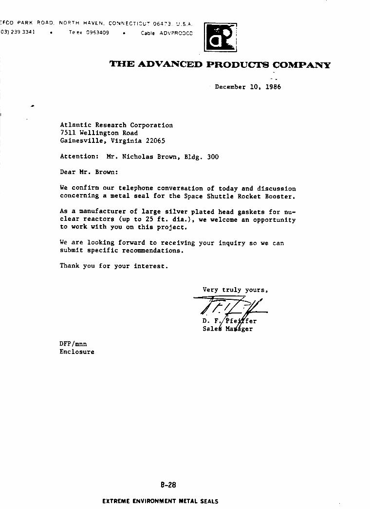
"FCO PARK ROAD. NORTH HAVEN, CONNECTICUT 064."3. U.S.A.
03) 239 3341 • Te!ex 0953409 • Cable ADVPRODCC
THE ADVANCED PRODUCI'$ COMPANY
December 10, 1986
Atlantic Research Corporation
7511 Wellington Road
Gainesvllle, Virginia 22065
Attention: Mr. Nicholas Brown, Bldg. 300
Dear Mr. Brown:
We confirm our telephone conversation of today and discussion
concerning a metal seal for the Space Shuttle Rocket Booster.
As a manufacturer of large silver plated head gaskets for nu-
clear reactors (up to 25 ft. dla.), we welcome an opportunity
to work with you on this project.
We are looking forward to receiving your inquiry so we can
submit specific recommendations.
Thank you for your interest.
DFP/mnn
Enclosure
Very truly yours,
D. F./Pfe_i'ferSale_ Ma_ger
B-28
EXTREME ENVIRONMENT METAL SEALS

.-oe
_ ... . o
-. . .-. ,, °
. . . . ..
_ IS
OF pOOR QUALITY
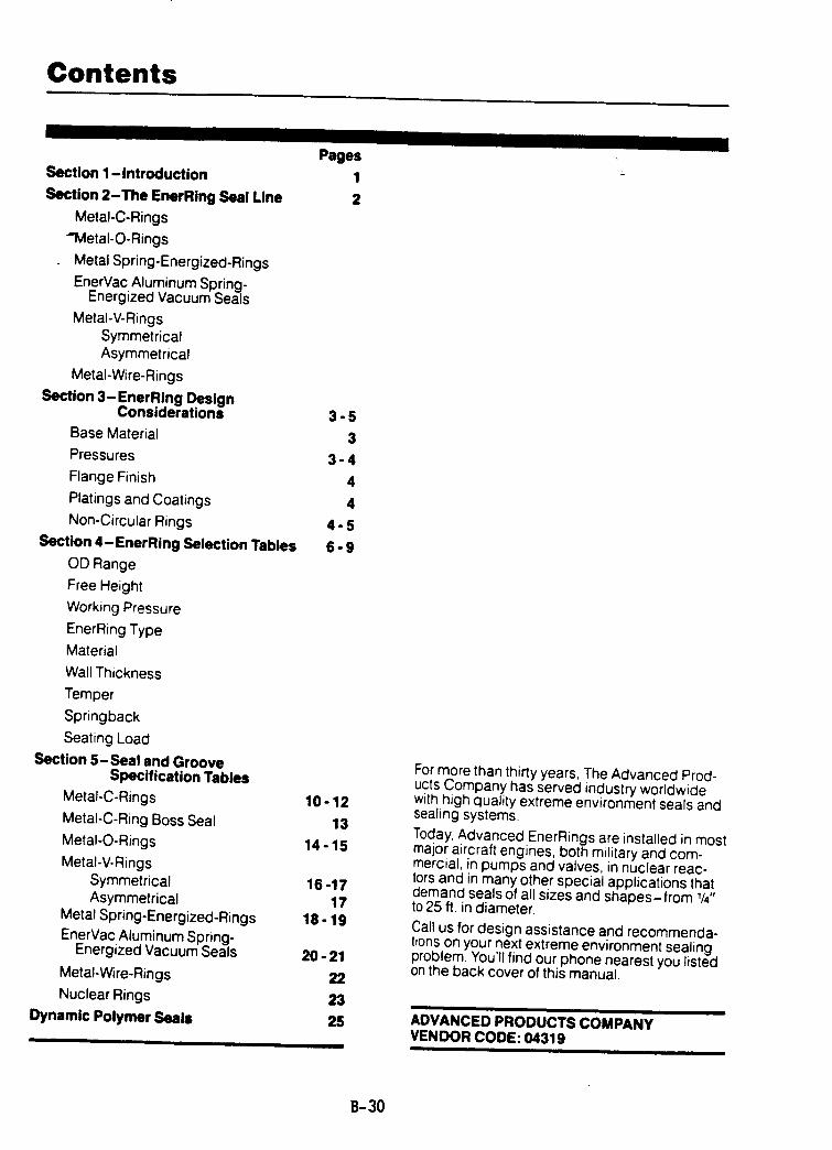
Contents
I II I Ill I IPages
1
2
Section 1-introduction
Section 2-The EnerRing Seal Line
Metal-C-Rings
_Vletal-O-Rings
Metal Spring-Energized-Rings
EnerVac Aluminum Spring-Energized Vacuum Seals
Metal-V-RingsSymmetricalAsymmetrical
Metal-Wire-Rings
Section 3-EnerRing DesignConsiderations 3 - 5
Base Material 3
Pressures 3 - 4
Flange Finish 4
Platings and Coatings 4
Non-Circular Rings 4 - 5
Section 4-EnerRing Selection Tables 6 - 9
OD Range
Free Height
Working Pressure
EnerRing Type
Material
Wall Thickness
Temper
Springback
Seating Load
Section 5-Seal and GrooveSpecification Tables
Metal-C-Rings 10 - 12
Metal-C-Ring Boss Seal 13
Metal-O-Rings 14 - 15
Metal-V-RingsSymmetrical 16 -17Asymmetrical 17
Metal Spring-Energized-Rings 18 - 19EnerVac Aluminum Spring-
Energized Vacuum Seals 20 - 21
Metal-wire-Rings 22
Nuclear Rings 23
Dynamic Polymer seals 25
For more than thirty years, The Advanced Prod-ucts Company has served industry worldwidewith high Quality extreme environment seals andsealing systems.
Today,Advanced EnerRings are installed in mostmajor aircraft engines, both military and com-mercial, in pumps and valves, in nuclear reac-tors and in many other special applications thatdemand seals of all sizes and shapes-from 1/4"to 25 ft. in diameter.
Call us for design assistance and recommenda-tions on your next extreme environment sealingproblem. You'll find our phone nearest you listedon the back cover of this manual.
ADVANCED PRODUCTS COMPANYVENDOR CODE: 04319
B-30
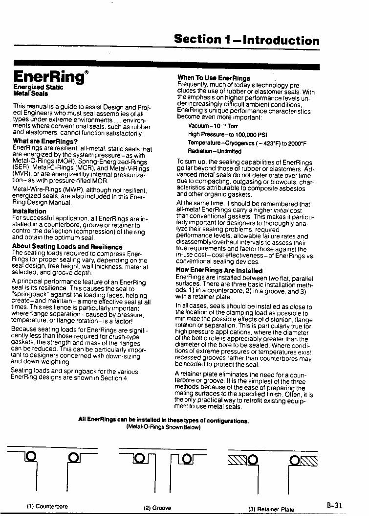
Section 1-Introduction
I
EnerRingEnergized StaticMeta/Seals
This manual is a guide to assist Design and Proj-ect Engineers who must seal assemblies of alltypes under extreme environments.., environ-ments where conventional seals, such as rubberand elastomers, cannot function satisfactorily.
What are EnerRings?EnerRings are resilient, all-metal, static seals thatare energized by the system pressure-as withMetal-O-Rings (MOR). Spring-Energized-Rings(SER), Metal-C-Rings (MCR), and Metal-V-Rings(MVR); or are energized by internal pressuriza-tion- as with pressure-filled MOR.
Metal-Wire-Rings (MWR), although not resilient,energized seals, are also included in this Ener-Ring Design Manual.
InstallationFor successful application, all EnerRings are in-stalled in a counterbore, groove or retainer tocontrol the deflection (compression) of the ringand obtain the optimum seal.
About Seating Loads and ResilienceThe seating loads required to compress Ener-Rings for proper sealing vary, depending on theseal design, free height, wall thickness, materialselected, and groove depth.
A principal performance feature of an EnerRingseal is its resilience. This causes the seal to
"springback" against the Ioadin(:j. faces, helpingcreate-and maintain-a more effective seal at all
times. This resilience is particularly importantwhere flange separation-caused by pressure,temperature, or flange rotation-is a factor!
Because seating loads for EnerRings are signifi-cantly less than those required for crush-typegaskets, the strength and mass of the flangescan be reduced. This can be particularly impor-tant to designers concerned with down-sizingand down-weighting.
Seating loads and springback for the variousEnerRing designs are shown in Section 4.
When To Use EnerRingsFrequently, much of today's technology pre-cludes the use of rubber or elastomer seals. With
the emphasis on higher performance levels un-der increasingly difficult ambient conditions,EnerRing's unique performance characteristicsbecome even more important:
Vacuum- 10 -" Ton"
High Pressure-to 100,000 PSI
Temperature-Cryogenics ( - 423°F) to 2000°F
Radiation- Unlimited
To sum up, the sealing capabilities of EnerRingsgo far beyond those of rubber or elastomers. Ad°vanced metal seals do not deteriorate over timedue to compacting, outgasing or blowouts, char-acteristics attributable to composite asbestosand other organic gaskets.
At the same time, it should be remembered thatall-metal EnerRings carry a higher initial costthan conventional gaskets. This makes it particu-larly important for designers to thoroughly ana-lyze their sealing problems, requiredperformance levels, allowable failure rates anddisassembly/overhaul intervals to assess theirtrue requirements and factor those against thein-use cost-cost effectiveness-of EnerRings vs.conventional sealing devices.
How EnerRings Are InstalledEnerRings are installed between two flat, parallelsurfaces. There are three basic installation meth-ods: 1) in a counterbore, 2) in a groove, and 3)with a retainer plate.
In all cases, seals should be installed as close tothe location of the clamping load as possible tominimize the possible effects of distortion, flangerotation or separation. This is particularly true forhigh pressure applications, where the diameterof the bolt circle is appreciably greater than thediameter of the bore to be sealed Where condi-tions of extreme pressures or temperatures exist,recessed grooves rather than counterbores maybe needed to protect the seal.
A retainer plate eliminates the need for a coun-terbore or groove. It is the simplest of the threemethods because of the ease of preparing themating surfaces to the specified finish. Often, it isthe only practical way to retrofit existing equip-ment to use metal seals.
All EnerRings can be installed in these types of configurations.(Metal-O-Rings Shown Below)
y(1) Counterbore (2) Groove (3) Retainer Plate
B-31
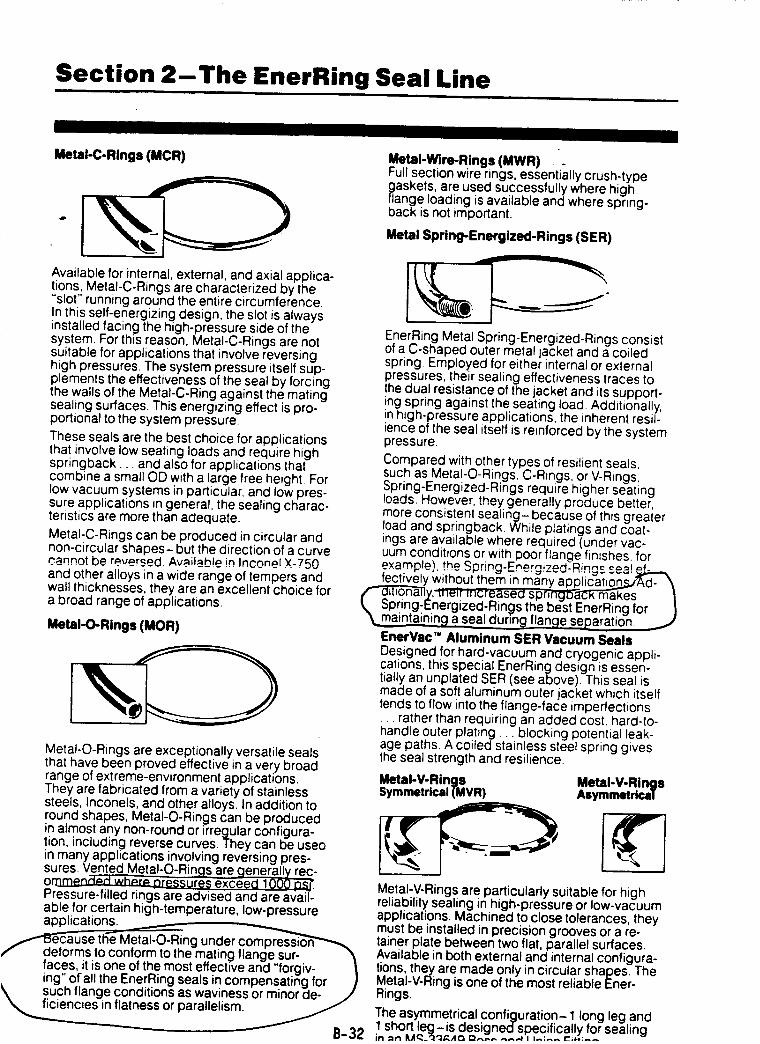
Section 2-The EnerRing Seal Line
II I I II I I
Metal-C-Rings (MCR)
Available for internal, external, and axial applica-tions, Metal-C-Rings are characterized by the"slot" running around the entire circumference.In this self-energizing design, the slot is alwaysinstalled facing the high-pressure side of thesystem. For this reason, Metal-C-Rings are notsuitable for applications that involve reversinghigh pressures. The system pressure itself sup-plements the effectiveness of the seal by forcingthe walls of the Metal-C-Ring against the matingsealing surfaces. This energizing effect is pro-portional to the system pressure.These seals are the best choice for applicationsthat involve low seating loads and require highspringback.., and also for applications thatcombine a small OD with a large free height. Forlow vacuum systems in particular, and low pres-sure applications in general, the sealing charac-teristics are more than adequate.
Metal-C-Rings can be produced in circular andnon-circular shapes-but the direction of a curvecannot be reversed. Available in !ncone! X-750and other alloys in a wide range of tempers andwall thicknesses, they are an excellent choice fora broad range of applications.
Metal-O-Rings (MOB)
Metal-O-Rings are exceptionally versatile sealsthat have been proved effective in a very broadrange of extreme-environment applications,They are fabricated from a variety of stainlesssteels, Inconels, and other alloys. In addition toround shapes, Metal-O-Rings can be producedin almost any non-round or irregular configura-tion, including reverse curves. They can be useoin many applications involving reversing pres-sures. Vented Metal-O-Rings are generally rec-omm_nclA,-t wh_r_..nressur_; exceed 1000 0._r.Pressure-filled rings are advised and are avail-able for certain high-temperature, low-pressureapplications. _.--
.,,_use th-'e-MetaI-O-Ring under compression--'_f deforms to conform to the mating flange sur-
faces, it is one of the most effective and "forgiv- I, ing" ofall the EnerRing seals in compensating for ]\ such flange conditions as waviness or minor de- I/
_...ficiencies in flatness or parallelism.B-32
II I I
Metal-Wire-Rings (MWR) - -Full section wire rings, essentially crush-typeaskets, are used successfully where highnge loading is available and where spring-
back is not important.
Metal Spring-Energized-Rings (SER)
1
EnerRing Metal Spring-Energized-Rings consistof a C-shaped outer metal lacket and a coiledspring. Employed for either internal or externalpressures, their sealing effectiveness traces tothe dual resistance of the jacket and its support-ing spring against the seating load. Additionally,in high-pressure applications, the inherent resil-ience of the seal itself is reinforced by the systempressure.
Compared with other types of resilient seals,such as Metal-O-Rings. C-Rings, or V-Rings,Spring-Energized-Rings require higher seatingloads. However, they generally produce better,more consistent sealing- because of this greaterload and springback While platings and coat-ings are available where required (under vac-uum conditions or with poor flanqe finishes, for
fec_liv_:lly - withOU_"_lt_'_e_'_ i_ 'm_ny-ap'_)'l_i_
/'_"dTf_"_y,-tn_r increased spnngo_es ISp[ing:Energized-Rings the best EnerRing for
\maintaining a seal during flange separation. ...,,/EnerVac'" Aluminum SER Vacuum SealsDesigned for hard-vacuum and cryogenic appli-cations, this special EnerRing design is essen-tially an unplated SER (see above). This seal ismade of a soft aluminum outer jacket which itselftends to flow into the flange-face imperfections... rather than requiring an added cost. hard-to-handle outer plating.., blocking potential leak-age paths. A coiled stainless steel spring givesthe seal strength and resilience.
Metal-V-Rings Metal-V-RingsSymmetrical(MVR) Asymmetrical
Metal-V-Rings are particularly suitable for highreliability sealing in high-pressure or low-vacuumapplications. Machined to close tolerances, theymust be installed in precision grooves or a re-tainer plate between two flat, parallel surfaces.Available in both external and internal configura-tions, they are made only in circular shapes. TheMetal-V-Ring is one of the most reliable Ener-Rings,
The asymmetrical configuration- 1 long leg and1 short leg-is designedspecifically for sealingir_l _if"1 __'_'_/I i''i D_ _1 i i_:^-- _;_.,:----
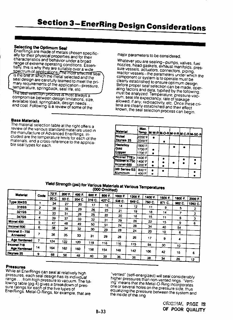
Section 3-EnerRing Design Considerations
II I I I
Selecting the Optimum SealEnerRings are made of metals chosen specific-ally for their physical properties and for theircharacteristacs and behavior under a broad
range of extreme operating conditions. Essen-tially, this is why they are suitable over a wide ,__ss,p_ectrum of a_Yne rr)osl ulfu_tlvu'-_eal \
fis the one anWhich the metal selected and the I| seal design are carefully teamed to meet the pri-I mary requirements of the application-pressure, I
L_mperature, springback, seal life, etc.Th-"e_u,_;s_uciion process i_ most aJways acompromise between design limitations, size,available load, springback, design needs...and cost. Following is a review of some of the
major parameters to be considered.
Whatever you are sealing-pumps, valves, fuelnozzles, head gaskets, exhaust manifolds, pres-sure vessels, actuators, connectors, piping,reactor vessels-the parameters under which thecomponent or system is to operate must beclearly established to ensure optimum design.Before proper seal selection can be made, oper-ating factors and data, typified by the following,must be analyzed: Temperature; pressure-vac-uum; seal life expectancy; rate of leakageallowed, if any; radioactivity, etc. Once these cri-teria are clearly established and their effectknown, the seal selection process can begin.
Base MaterialsThe material selection table at the right offers areview of the various standard materials used inthe manufacture of Advanced EnerRings. In-cluded are the temperature limits for each of thematerials, and a cross-reference to the applica-
ble seal types for each.
_X. ¸
Ihteri:l Temp. M-W-RiNickel 2200:F •Haynes2S 2000+FHastelloy 1800"1=1Gold 1700T •
1700-'1= •iCopper
(_ i1400TIi1400_F •Inconel-.600 1200"1: •
300Sedes-SS]Aluminum i 400JFI -"
M-O-R=M-V-RM-C-R M-SE-Ri
I, ,
J . J , i •
Yield Strength (psi) for Various Materials at Various Temperatures(000 Omitted)
72_RMaterial Code
20C.
Type 304SS 1 34316SS 2 38
' 321SS 3 33
347SS 4 39
,Mon_400 5 47Incone1600 6 38
InconelX-7507 36Annealed
Age Hall:len•d 7 124
hlcon_ 718 14 164
Haynes 25 9 68
_,001=.400F. so01=.=0+=. +ooo"J=.+_F'. 1400F'. Ir,OOF'..C. 204+C.3"m_C.4ZTC. inC. r,49c. 7r,oc. s71c.
27 2o _7 15 14 _2 _1 935 29 26 23 2_ _9 18 _,43_ 28 26 22 2o 18 _s _37 33 32 31 29 26 22 15
48 49 50 51 24 28 34 40
34 32 30 29 28 24 20 10
35 33 31 29 28 26 17 9
122 120 118 116 116 115 94 30
162 160 158 154 148 142 106 42
'58 48 40 39 36 36 38 34
1800-1:. 2000:1=.
982_C. 1093 C.
5 2
7 3
6 3
9 6
54
6
4
10
15 6
26 12
PressuresWhile all EnerRings can seal at relatively highpressures, each seal design has its individualrange.., from high pressure to vacuum. The fol-lowing table (pg.4) gives a breakdown of pres-sure ratings for each of the five types ofEnerRings, Metal-O-Rings, for example, that are
B-33
"vented" (self-energized) will seal considerablyhigher pressures than non-vented rings. "Vent-ing" means that the Metal-O-Ring incorporatesone or several holes on the pressure side, thusequalizing the pressure between the system andthe inside of the ring.
OF POOR QUAUTY
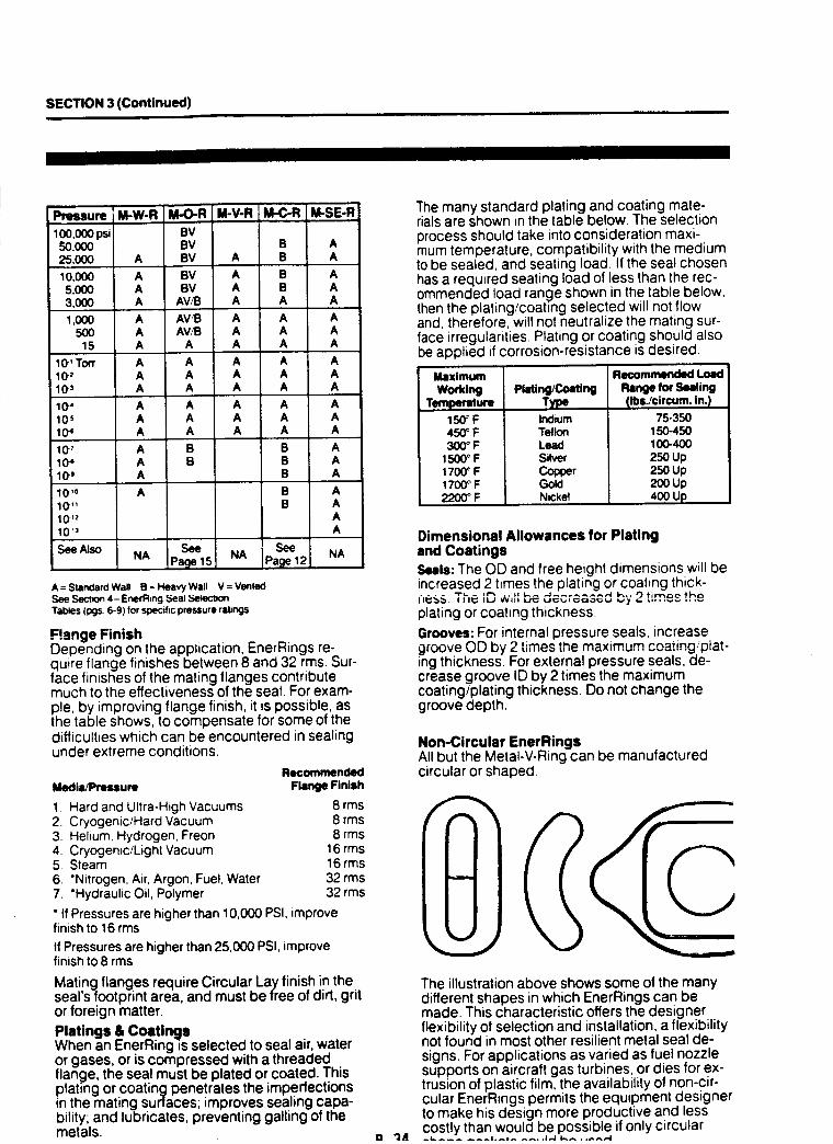
SECTION 3 (Continued)
Pressure
100,000 psi BV,_0,000 BV B A
25,000 A BV A B A
10,000 A BV A B A
5,000 A BV A B A
3,000 A AV,_B A A A
1,000 A AV_ A A A
500 A AV,t3 A A A
15 A A A A A
10' Torr A A A A A
102 A A A A Ai 103 A A A A A
10 _ A A A A A
105 A A A A A
10 _ A A A A A
107 A B B A10_ A B B A10g A B A
10 `0 A B AlO" B A10 'z A
10 '3 A
See ' SeeSeeAlso NA Page 1$1 NA IPage121 NA
A = Standard Wall B = Heavy Wall V = VentedSee Section 4-EnerRmg Seal 5etect_on
Tables (Ixjs, 6-9) for spec'ff_cwessure ral_KJS
Flange FinishDepending on the application, EnerRings re-quire flange finishes between 8 and 32 rms. Sur-face finishes of the mating flanges contributemuch to the effectiveness of the seal. For exam-ple, by improving flange finish, it is possible, asthe table shows, to compensate for some of thedifficulties which can be encountered in sealingunder extreme conditions.
Media/Pressure
1. Hard and Ultra-High Vacuums2. Cryogenic/Hard Vacuum3. Helium, Hydrogen, Freon4. Cryogenic/Light Vacuum5. Steam6. *Nitrogen, Air, Argon, Fuel, Water7. "Hydraulic Oil, Polymer
• If Pressures are higher than 10,000 PSI, improvefinish to 16 rms
If Pressures are higher than 25,000 PSI, improvefinish to 8 rms
Mating flanges require Circular Lay finish in theseal s footprint area, and must be free of dirt, gritor foreign matter.
Platings & CoatingsWhen an EnerRing _sselected to seal air, wateror gases, or is compressed with a threadedflange, the seal must be plated or coated. Thisplating or coating penetrates the imperfectionsin the mating surlaces; improves sealing capa-bility; and lubricates, preventing galling of themetals.
Recommended
Flange Finish
8 rms8 rms8 rms
16 rms16 rms32 rms32 rms
"JA
The many standard plating and coating mate-rials are shown in the table below. The selectionprocess should take into consideration maxi-mum temperature, compatibility with the mediumto be sealed, and seating load. If the seal chosenhas a required seating load of less than the rec-ommended load range shown in the table below.then the plating/coating selected will not flowand, therefore, will not neutralize the mating sur-face irregularities. Plating or coating should alsobe applied if corrosion-resistance is desired.
MaximumWorking
Temperature150_F450oF300°F
1500cF1700_F1700° F2200° F
Plating/CoatingTyp
Indium
Teflon
Lead
Silver
Copper
GoldNckel
Recommended Load
Range for Sealing
(Ibs./circum. in. !
75-350
15o-450100-400250 Up250 up2ooup400 Up
Dimensional Allowances for Platingand Coatings
Seals: The OD and free height dimensions will beincreased 2 times the plating or coating thick-i|ess. The ;D ..... "^ " ....... " by 2 t;'_'_ th,.,plating or coating thickness.
Grooves: For internal pressure seals, increasegroove OD by 2 times the maximum coating'piat-ing thickness. For external pressure seals, de-crease groove ID by 2 times the maximumcoating/plating thickness. Do not change thegroove depth.
Non-Circular EnerRingsAll but the Metal-V-Ring can be manufacturedcircular or shaped.
The illustration above shows some of the manydifferent shapes in which EnerRings can bemade. This characteristic offers the designerflexibility of selection and installation, a flexibilitynot found in most other resilient metal seal de-signs. For applications as varied as fuel nozzlesupports on aircraft gas turbines, or dies for ex-trusion of plastic film, the availability of non-cir-cular EnerRings permits the equipment designerto make his design more productive and lesscostly than would be possible if only circular
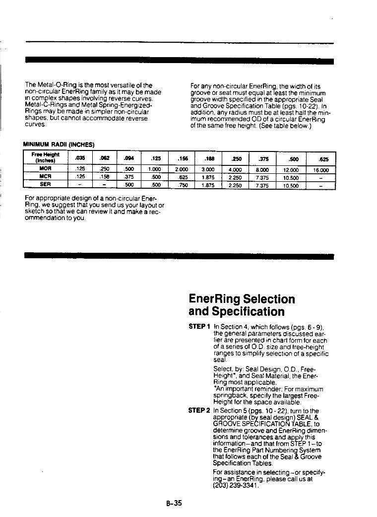
The Metal-O-Ring is the most versatile of thenon-circular EnerRing family as it may be madein complex shapes involving reverse curves.Metal-C-Rings and Metal Spring-Energized-Rings may be made in simpler non-circularshapes, but cannot accommodate reversecurves.
MINIMUM RADII (INCHES)
Free Height(Inches) .035 .062 .094 .125
MOR .125 .250 .500 1.000
MCR 125 158 375 .500
SER - - 500 500
For appropriate design of a non-circular Ener-Ring, we suggest that you send us your layout orsketch so that we can review it and make a rec-ommendation to you.
For any non-circular EnerRing, the width of itsgroove or seat must equal at least the minimumgroove width specified in the appropriate Sealand Groove Specification Table (pgs 10-22). Inaddition, any radius must be at least half the min-imum recommended OD of a circular EnerRingof the same free height. (See table below.)
.156 .1M .250
2.000 3.000 4.000
.625 1.875 2.250
.750 1.875 2.250
.375
8000
7.375
7.375
.500 .625
12.000 16000
10.500
10.500
EnerRing Selectionand SpecificationSTEP 1
STEP 2
In Section 4, which follows (pgs 6 - 9),the general parameters discussed ear-lier are presented in chart form for eachof a series of O.D. size and free-heightranges to simplify selection of a specificseal.
Select, by: Seal Design, O.D., Free-Height', and Seal Material, the Ener-Ring most applicable.An important reminder: For maximum
springback, specify the largest Free-Height for the space available.
In Section 5 (pgs. 10 - 22), turn to theappropriate (by seal design) SEAL &GROOVE SPECIFICATION TABLE, todetermine groove and EnerRing dimen-sions and tolerances and apply thisinformation-and that from STEP 1-tothe EnerRing Part NumberingSystemthat follows each of the Seal & GrooveSpecification Tables.
For assistance in selecting-or specify-ing-an EnerRing, please call us at(203) 239-3341.
B-35
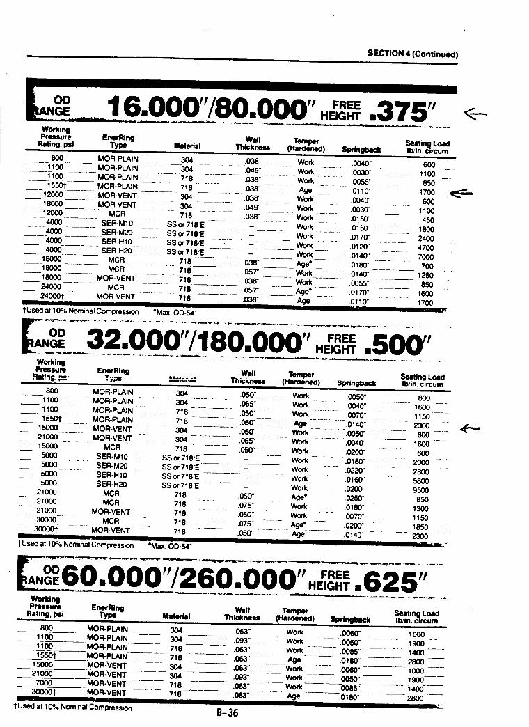
SECTION 4 (Continued)
OD
WorkingPressure EnerRing Wall Temper Seating Load
Rating, psi Type Material Thickne_ (Hardened) Springback Ib/in. circum
800 MOR-PLAIN 304 .038' Work1100 MOR-PLAIN 304 .049" Work1100 MOR-PLAIN 718 .038" Work15501" MOR-PLAIN -- " 718 ....... 038" -- -- Age .......
12000 MOR-VENT 304 038" Work18000 MOR-VENT 304 .049" Work12000 MCR 718 .038" Work4000 SER-M10 SS or 718E - Work
4000 SER-M20 SSor 718/E -. ..... Work ....4000 SER-HIO SS or 718YE ...... - Work4000 SER-H20 SS or 718/E - Work
--18000 ..... MCR 718 ....... .038" -----_-- Age" -- ....1_oo McR 718 .o5T work18000 ..... MOR-VENT .... 718 038" ------ Work
__ 24000 .._ MCR ....... 718 ,0ST' Age" _ ....240001" MOR-VENT 718 .038" Age
II '" ' • =' mtUsed at 10% Nominal Compression "Max. 00-54"
.0040" 600•0030" 1100.0055" 850.0110" 1700.0040" 600.0030" 1100
.0!50" 450
.0150" 1800
.0170" 2400.0120" 4700.0140" 7000.0180" 700.0140" 1250.0055" 850.0170" 1600,0110" 1700
E....___. __.._.I VVtl /_m I__ VmVV v .....I=IEIGH'rl mI_Ii__V .V .
WorkingPressure EnerRing Wall Temper Seating Load
Rating. pt; Type _t=ml Thickness (Haraenea) $prlngbaCk Ib/in. circum
800 MOR-PLAIN 304 .050" Work .0050" 8001100 MOR-PLAIN 304 .065" Work 0040" 160011oo ,OR-PU',IN 7_s o=--_' wo_ .oo7o" .,I.5o
___.15501": _:'_:_. MOR-PLAIN =__ '__: 718 ....... .050" ....... Age--_::---:.0140" -...... 2300 __.-_:150(:0 MOR-VENT 304 .050' Work .0050" 80021000 MOR-VENT 304 .065" Work .0040" 160015000 MCR 718 050" Work .0200" 6005000 SER-M10 SS _ 718]E - Work .0180" 20005000 SER-M20 SS or 71&E - Work .0220" 28005000 SER-H 10 SS or 718_E - Work- .0160" 58005000 SER-H20 SS or 718 E - Work .0200" 9500
.
___ 21000 MCR 718 .05_' Age* .0250" 85021000 MCR 718 .075" Work O180" 130021000 MOR-VENT 718 .050" Work .0070" 1150
---" 30000- " - MCR 718 --- " .075" - .... Age" -..... .0200" -" 1850 "-" 300001: .... MOR-VENT .... 718 ...... .050"- ...... Age .0140" - .... 2300 =--
,n... I I I II II I t ¢11_r l"
tUsed at 10% Nominal Compression =Max. O1:)-54"
'"" ..........• __, ,E! HT.625"WorkingPressure EnerFIing Wall Temper Seatin_ Load
Rating, psi Type Material Thickness (Hardened) Springback Ib/in. c,rcum=l I1 I I I I J I Ill
800 MOR-PLAIN 304 .063" Work .0060" 1000MOR-PLAIN 304 .093" Work .0050" 1900MOR-PLAIN 718 ..... .063"--" Work - --- .0085" 1400 --
MOR-PLAIN 718 .063" Age .0180" 2800 ___MOR-VENT 304 .063" ++ --- Work ....... _0060" 1000MOR-VENT 304 .093" Work .0050" 1900MOR-VENT 718 .063" Work .0085" 1400
MOR-VENT 718 .063" Age .0180" 2800= _' II I I II
B-36
11001100
155O1"1500O21000
7OOO
3OOOO1"
1'Used at 10% Nominal Compressu_
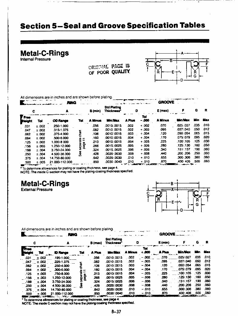
Section 5-Seal and Groove Specification Tables
Metal-C-RingsInternal Pressure
OF POORQUAUTY
All dimensions are in inches and are shown before plating.
_. :....:.
C A B (rain)
F_=m..................Tol OD Range Tol. _ A Binul Bin/Max A Plul
.031 ± .002 .250-1.050 .056 .0010,'.0015 .052
.047 ± .002 .315-1.375 ,¢:: .082 .0010, .0015 .002
.062 ± .002 .375-4.000 j:_ .106 .0010,'.0015 .003¢.1
.094 ± .002 .500-6.000 _ -- .160 .0010/.0015 .004
.125 ±.003 1.000-8000 i_ .213 .0010'.0015 .004.156 ± .003 1.250-12.000 266 .0015/.0025 .005.188 ± .004 3.750-24.000 .324 .0015,.0025 .006
.428 .0020.0030 .008.250 ± .004 4.500-36.000 el).375 ± .004 14.750-80.000 .642 .0020,,0030 .010500 ± .005 21.000-112.000 .850 .0030..0040 .010
._ _, ............. GROOVEStd PlatingThickneu" D E (max) G
Vw" ........ "
Tol
• To determine allowances for plating or coating thickness, see page 4.NOTE: The inside C-section may not have the plating,'coating thckness specified.
-_00
+ .002+ .003+.004+.004+ .005+.006+006+.008+ .010+ .010
F R
A BinuI Mtn/Mm[ Bin M==
.070 .025,.027 .035 .010
.095 .037/.040 .050 .012
.120 .050'.054 .065 .015.170 .075/.079 .095 .020225 .105/.105 .125 .030280 .125,'.130 .160 .050.340 .151_.157 .190 .060.440 .200.206 .250 .060.655 300,305 .380 .060.870 .400'.406 .500 .060
-J', "...._J,_'lEr,_-,_p._;_¢_"._,_.__..,_,,_ .',_ . .
Metal-C-RingsExternal Pressure
C
T-
t
-T
All dimensions are in inches and are shown before plating.
.... m.G ............. ........... G.oowZ--'.Std Plating"_ick_t_" D E (rain) F G RC A B (max)
Till
+.l_O. __ APkal..__.._,.. Bin/Mix Bin Mix
_ - .002 ..... .070 .025/.027 .035 .010_- .003 .095 .037/.040 .050 .012
-.004 .120 _ .050/.054 .065 .015- .004 _ .170 .... .075/.079 .095 .020-.005 .225 .... _I00/.105 .125 .030- .006 .280 .125/.130 .160 .050-.006 .340 .151/.157 .190 .060-.008 .440 .2001.206 .250 .050
- .010 .655 .300/.306 .380 .060•010 - .010 .870 .400/.406 .500 .060
L, • -| _._L"_II' _%_ I '" -u,_.,-=-a_ . _,&...
Ilkl/lllx Ak
. _ .031 ± .002 __ .195-1.000 .056 .0010/.0015 .002_ .047 ± .002 __ .225-I .375 __ t: .082 .0010/.0015 .002
.062 ± .002 ._ .250-4.000 _ .106 .0010/.0015 .003.094 ± .052 _ .300-6.000 m .,- .160 .0010/.0015 .004
.125 ±.003 .750-8.000 i_ .213 .0010/.0015 .004_ .156 ±.003 1.250-12.000 .266 .0015/.0025 .005_.188 ±.004 3.750-24.000 .324 .0015/.0025 .006,_..250 " _±.004 4.500-36.000 u_ .428 .0020/.0030 .008
.375 ± .004 14.750-80.050 .642 .0020/.0030 .010
.500 ± .005 21.000-112.000 .850 .0030/.0040
• To determine allowances for plating or coating thickness, see page 4.NOTE: The inside C-section may nol have the plating/coaling thickness specified.
B-37
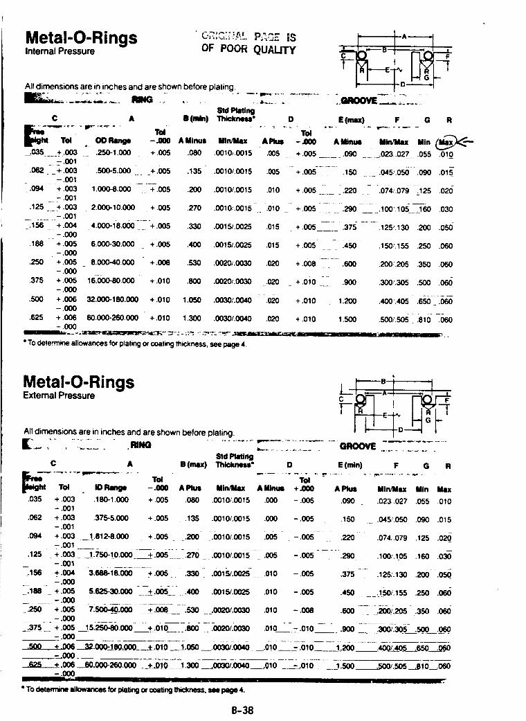
Metal-O-RingsInternal Pressure OF POOR QUALITY
All dimensions are in inches and are shown before plating,
' A'----_
Std PU_n9A II (rain) Thickness"
,. OO Range - _00 A Minus Min/Max
.035 .... +.003 .250-1.000 _ . + .005 .080 .0010_.0015- .001
.062 +.003 .500-5.(X)0 i__ +.005 .135 .0010/.0015- .001
.094 + .003 1.000-8.000 + .005 .200 .0010/.0015 .010=_
- .001.125 + .003 2.000-10.000 + .005
........ - .001_.156 __ + .004 -4.000-i8.000 ----+ .005
-.000
.188 + .005 6.000-30.000 + .005 .400 .0015/.0025 .015-.000
.250 +.005 _ 8.000-40.000 +.008 .530 .0020/.0030 .020--.000
.375 + .005 16,000-80.000 + .010 .800 .0020/.0030 .020--.000
.500 + .006 32.000-180.000 +.010 1.050 .0030/.0040 .020--.000
.625 + .006 60.000-260.000 + .010 1.300 .0030/.0040 .020--.000
I] ,... - ," "_L -"_ "r _ _.." • ::;_ "" --"Zr _L ": -."_'-. 11'_- _ v._._v,m-_,_ ..._K,__
• To determine allowances for p ating or coat ng thickneSS see page 4,
O E (max) F
AP_.s
.005
.005
G R
-,000 A Mingl MINMIx Min __
+ .005 ....... .090 ___i ..023..027_ .055 .0!0
+.oos------ .150 i045;.056-.090 .o_s-
+ .oos- ___.220 - -.07.4_.ozg_--j25.020
2;,0 .0010...0015=_.0i0 _- +.005--_ __-.290- -__.1oo,.lO__._ o30
.330 .0015/.0025 - .015 + .005 --- .375- ..... .125/.130 200 .050-
+.oo5..... :45o .150'.155 .250 .060
+ .OOB ..... .Boo .200'.205 .350 .060
+.0i0 -- .9oo .300.,.305.soo .066
+.010 1.200 .400.405" .6_6-_-.6_
+.010 I.s00 .500/.sos .e10-_T-060
,,--.--- ...
Metal-O-RingsExternal Pressure
All dimensions are in inches and are shown before plating.
Std Platin9C A B (max) Thickness* D
4
C I F
' I--_--I---E.-P_ I IR/ j
t_o__ orE (mtn) F G R
-.000 A Plus
.035 + .003 .180-1.000 + .005 .080 .0010/.0015 .000- .001
.062 + .003 .375-5.000- .001
.094 + .003 ._ 1_.812-8.000- .001
:125 +.oo3___.750:!0.ooo- .001
:._ss _+.004 3.S_-le.OOO+.oos .330 ,001_.0025-_.01o--,000
_--.188 - + .005 5.625"30.000 ---+.005-_ .400 :0015/.0025 .010.... _ .000
250 +.005 -7:_:0()0- _,,(_----:530 .0020/.0030 .010--.000
TelMin/Mu A Minull + _ A Plul Min_lu Min Max
- .005 .090 .023.027 .055 010
+ .005 .135 .00101.0015 .000
+ .005 _ _.200 _ .0010/.00t5 _ .005
+.oo_: _:.2"_o/ :OOlO/OO'is-.oo5
- .005 .150 .045/.050 .090 .015
- .005 .220 .074;.079 .125 .020
-oo5 .29o- .1oo,,.tos.ISO .o_
-.005 .375 .... .125/.130 .200- .050
-.005 .450 -___._i50/.155 .250 .060
-.008 .600 .... :_0!:205- .350 .060
-._.375 ::- + .005 15._:-000- - + :0i0------.800- :_ _00201:0030 .010 -- - .016 -- - .900 .300/._305- .500 .060_.000
.500 +.om___.ooo-jeo_ooo+.010____toso:_.ix_:O046_.Oio----i)10----_2Y)o .... 400/405 .s_ oso-- ,000
__006_._60.000.L_0.000 +.010__j._,00---_003_:0040.010 ___-_010____1.s00 ._soo/.50s___.__.__0.060--.000
B-38
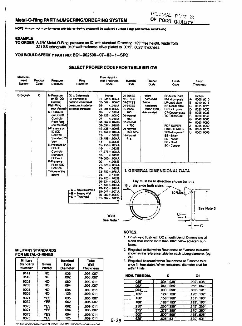
Metal-O-Ring PART NUMBERING/ORDERING SYSTEM OF POOR QUAtJTy
NOTE: Any Pan no| in ¢o_brrnance wwththis nurnl:erklg systern wig be assigned a unclue 5-dig+tpan nun_eq and drawing
EXAMPLETO ORDER: A 2'/2" Metal-O-Ring, pressure on ID, with standard ID venting,.125" free height, made from
321 SS tubing with .010" wall thickness, silver plated to .0015"/.0025" thick.
YOU WOULD SPECIFY PART NO: EOI-002500-07-03-1-SPC
SELECT PROPER CODE FROM TABLE BELOW
Free Height xme_ Product Pressure Ring Wall Thmkness Material Temper Finish
System Co¢le Direction Dhameter Code Code Code CodeFinish
Thickness
E-Engish 0 N-Pressure
on ID (OI3Control)
Plain Ring(no4 Vente¢
M-Pressureon OD (IDControl)-
Plato Ring(not Venta¢
I-Pressure onID (00Control)-Standard It"Vent
E-Pressure on
OD (IDControl)-StandardOD Vent
P-Pressure
Filled (OOControl)
Y-None of theabove
(1) to 3 dearnals(2) d_neter is
for internal
pressure: inside forexternal pressure
_i = Stenden:l Wall
Heavy Wall= Thin Wall
Inches01-O35 × 006 A02-.062 x .006C03- x .0t0A04-.094 x 006 C
05- x .010A06-.125x .008C07- x .010A06-.062 x .014 •09-.094 × .018B10-.125 x 020 B11-.156 × .016 A12- x .020B13-.188 _ .020 A14- x .025 B15-250 x .025 A16- x .032 B17-375 x .038 A18- x .049B19-500 _ 050 A20. x .065 B21 -.625 x .063 A22- x 093 B23-.750 x 075 A24- x ,113B25-.125 x .012 B26-324 x 032 A27-.435 x .044 A28-.455 x 046 A29-.047 x 007 A30-.080 x .006 C31-.062 x .012B
1'
Weld
See Note 1
MILITARY STANDARDS
FOR METAL-O-RINGS
MilitaryStandard
Number
9141 NO
9142 NO
9202 NO
9203 NO
9204 NO
9205 NO
9371 YES
9372 YES
9373 YES
9374 YES
9375 YES
9376 YES
Silv_
Piat_l
Nominal Tube
Tube Wall
Diameter Thickness
.035 .005..007
.062 .005.007
.062 .009:O11
.094 .005.007
.094 .009'.011
.125 .009i.011
.035 .005,,'.007
.062 .005/.007
.062 .009'.011
.094 .005,.007
.094 .009.'.011.125 .009_.011
01-304SS02-316SS03-321SS04-347SS05-Monet
4OO06-1nco_
6OO07-1nconel
X-75009-Haynes
25 (L605)14-1nconel
718
l-Workhamoned
2-Agehardened
(short cycle)4-AnnealeO
SP-Sdver PlateIP-Indium plate
LP-Lead plateNP-Nickel plateGP-Gold plateCP-Copper plateTC-Teflon Coat
FOR SUPER
FINISH PARTS
SFX- UnplatedSS-SdverSN-NK:kelSG - Gotd
SC-Col_oer
InchesA- 0005 O010B- O010 O015C- .0015 0025D- .0020 0030E- .0025 0035F- .00300040G- 0040 0060
H- .0060.0090J- .0035 0050K- .0050 0070L- .0003.0005
i. GENERAL DIMENSIONAL ....I,/Pt I AI_
Lay must be in direction shown for this
16 distance both sides. _
_ Cl_k -I "---'r--
i
NOTES:
1. Finish weld flush with OD smooth blend. Dimensions at
blend shall not be more than .002" below adjacent sur-laces.
2. Ring shall be flat within Roundness or Flatness tolerance
shown in the reference table for each tubing diameter. (10g.24)
3. Ring shall be round within Roundness or Flatness toler-
ance (in free state). When restrained, diameter shall bewithin limits.
See Note 3
NOM. TUBE DUL C Cl
.035" .034"/.038" .029"/.038"
.062" .061 "/.065" .056"/.067"
.094" .093" :098" .089"/.101"
.125" .124"/.128" .120"'.132"
.156" .156"/.160" .151",'.160"
.188" .188"/.193" .183"/.193"
.250" .250"/.255" .245"_.255"
.375" .375",.380" .370", .380"
.500" .500"/.506" .495";.506"
.625" .625"/.621" .620",.631"B-3gTn firtrl=l'_-H'l'tr_iaf@_¢h NI tml'w,r t*eD U_ _tIntt:=rrl¢ I=h_t¢ r_rPall
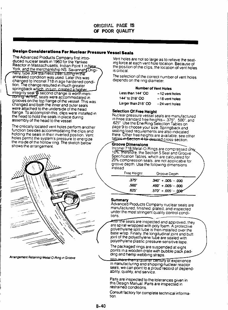
OR_G]_',!_L PAGE IS
OF POOR QUAUTY
JI I
Design Considerations For Nuclear Pressure Vessel Seals
The Advanced Products Company first intro- Vent holes are not so large as to relieve the seat-duced nuclear seals in 1960 for the Yankee ing force at each vent hole location. Because ofReactor in Massachusetts, Indian Point 1 in_York, and the merchantship NS, Savannah._ Origi-
/,_n_y, type 304 slaJnless steel [uDing in [ne /[ annealed condition was used. Later this was /
changed to Inconel 718 in age hardened condi- /I tion. The change resulted in much greater(
springback which, in turn _rp.ated a hinhP.rintegrity seal.__second change is worth men-
seals were accommodated ingrooves on the top flange of the vessel. This waschanged and both the inner and outer sealswere attached to the underside of the head
flange. To accomplish this, clips were installed inthe head to hold the seals in place duringassembly of the head to the vessel.
The critically located vent holes perform anotherfunction besides accommodating the clips andholding the seals in their inverted position. Ventholes permit the system's pressure to energizethe inside of the hollow ring. The sketch belowshows the arrangement.
the position of the clips, the location of vent holesis critical.
The selection of the correct number of vent holesdepends on the ring diameter.
Number of Vent Holes
Less than 144" OD - 12 vent holes
144" to 218" OD - 18 vent holes
Larger than 218" OD -24 vent holes
Selection Of Free HeightNuclear pressure vessel seals are manufacturedin three standard free heights-.375", .500", and.625". Use the EnerRing Selection Tables onpage 9 to choose your s_ze. Springback and
ArrangementRetainingMetal-O-Ringin Groove
seating Ioacl requirements are also indicatedthere. Other free heights are available: see other
ta].b.P_r_ Sect;o. 4 for dc_section/ Groove Dimensions
n,",-,n_l 718 Meta -CLR n S a r,=co,',,,',,essed o,,"r_.... ,.... _ ........ g ..... p,,/ _n_nleretore, the Section 5 Seal and Groov
/ Specification Tables, which are calculated for \/ 20% comoression seals, are not applicable for \I groove depth Use the following d_mensions )
instead /J."-_- - - - _. Free Height Grc,_._...ov,=n!pt.__._.h /
/
SummaryAdvanced Products Company nuclear seals aremanufactured, finished, plated, and inspectedunder the most stringent quality control condi-tions.
_cted and approved, they_'_
are spiral-wrapped with poly foam. A protective/" polyethy elne split tube is then installed over the
/ base wrap. Finally, the longitudinal joint and butt_joint of the polyethylene tube are sealed with
polyethylene plastic pressure-sensitivetape. )The packaged rings are suspended at eight /points in a wooden crate with bubble pack pad-
\ cling and hemp webbing straps .._.___.._w_,q mcrct,'-,;,,, ,-,qua'wte_ uenlury of experience
in manufacturing and shipping nuclear reactorseals, we can point to a proud record of depend-ability, quality, and service.
Parts are inspected to the tolerances given inthis Design Manual. Parts are inspected inrestrained conditions.
Consult factory for complete technical informa-tion.
B-40
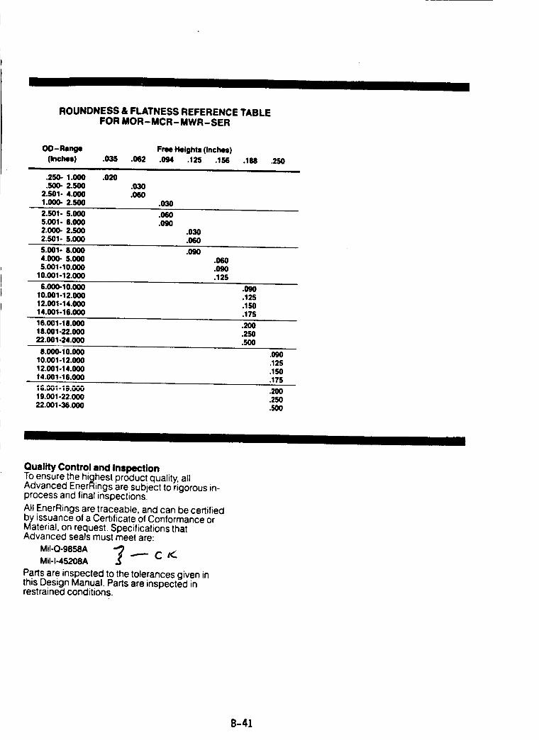
ROUNDNESS & FLATNESS REFERENCE TABLEFOR MOR- MCR- MWR- SER
OD- P,enge Free Heights (inches)
(Inches) .035 .062 .094 .125 .156 .188i i
.250- 1.000 .02O
.500- 2.500 .0302.501- 4.000 .0601.000- 2.500 .O3O
.250
2.501- 5.000 .0505.001- 6.000 .0502,000- 2,500 ,03O2.501- 5.000 .060
5.001- 8.00O .0904.0OO- 5.000 .0605.001-10.000 .090
10.001-12.000 .125
6.000-10.000 .00010.001-12.000 .12512.001-14.000 .15014.001-16.000 .175
16.001-18.000 .20018.001-22.000 .25022.001-24.000 .500
8.000-10.000 .O9010,001-12.000 .12512,001-14,000 .15014.001-16.000 .175
IG._1-I;.000 .2OO19,001-22.000 .25022.001-36.000 .500
II I
Quality Control and InspectionTo ensure the highest product quality, allAdvanced EnerRings are subject to rigorous in-process and final inspections.
All EnerRings are traceable, and can be certifiedby issuance of a Certificate of Conformance orMaterial, on request. Specifications thatAdvanced seals must meet are:
MiI-Q-9858A _ _- C /(-.MiI-I-45208A .3
Parts are inspected to the tolerances given inthis Design Manual Parts are inspected inrestrained conditions
B-41
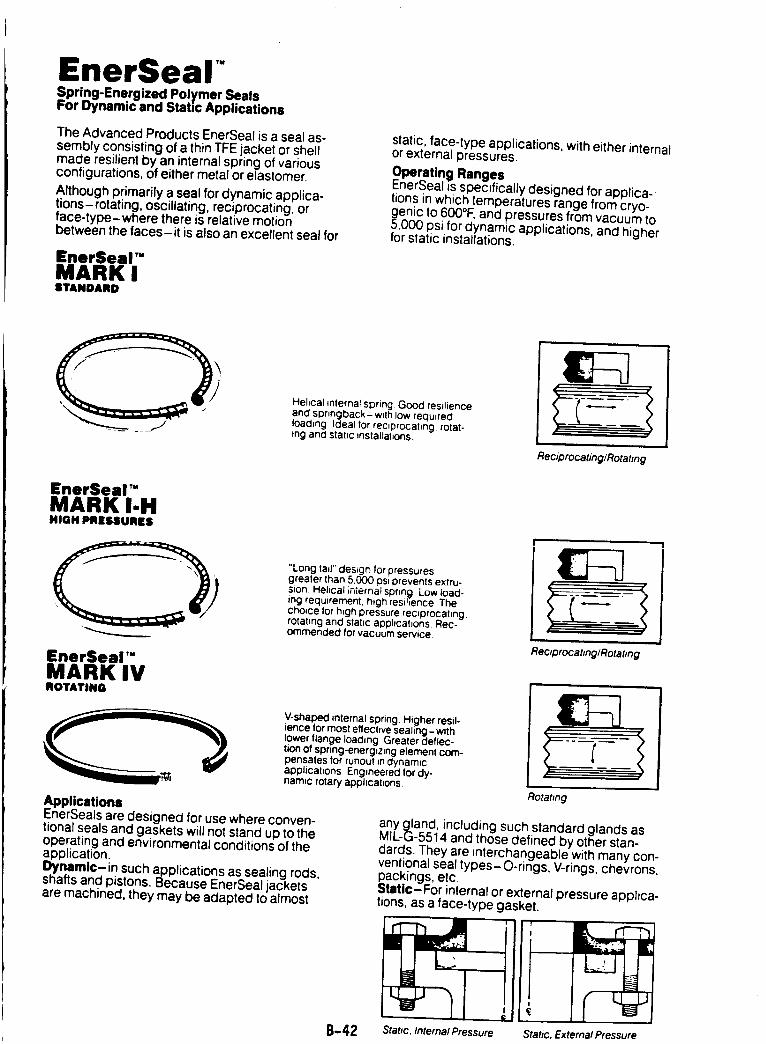
EnerSeal"Spring-Energized Polymer SealsFor Dynamic and Static Applications
The Advanced Products EnerSeal is a seal as-sembly consisting of a thin TFE jacket or shellmade resilient by an internal spring of variousconfigurations, of either metal or elastomer.
Although primarily a seal for dynamic applica-tions-rotating, oscillating, reciprocating, orface-type-where there is relative motionbetween the faces-it is also an excellent seal for
EnerSeal"MARK ISTANDARD
static, face-type applications, with either internalor external pressures.
Operating RangesEnerSeal is specifically designed for applica-tions in which temperatures range from cryo-
enic to 600°I:, and pressures from vacuum to,000 psi for dynamic applications, and higher
for static installations.
Helical internal spring Good resilienceand springback- wllh low requiredloading Ideal for reciprocating, rotat-ing and static installations
Reciprocating/Rotating
EnerSeal"MARK I-HHIGH PRESSURES
QEnerSeal TM
MARK IVROTATING
"Long tail" des=on for pressuresgreater than 5,000 psi orevents extru-sion Helical internal sprfn 9 Low ioad-ing requirement, high resihence The
choice for h_gh pressure reoprocatmgrotating and stahc apphcat_ons Rec-ommended for vacuum serwce
V-shaped internal spring. Higher resil-ience for most effective sealing-with
lower flange loading Greater deflec-tion of spring-energizing element com-pensates for runout Jndynamicapplications Engineered for dy-nam=c rotary apphcat_ons.
#
ReclprocatinglRotating
ApplicationsEnerSeals are designed for use where conven-tional seals and gaskets will not stand up to theoperating and environmental conditions of theapplication.Dynamic- in such applications as sealing rods,shafts and pistons. Because EnerSeal jacketsare machined, they may be adapted to almost
Rotating
B-42
any gland, including such standard glands asMIL-G-5514 and those defined by other stan-dards. They are interchangeable with many con-ventional seal types-O-rings, V-rings, chevrons,¢_ackings,etc.
tati¢-For internal or external pressure applica-tions, as a face-type gasket.
Stattc, Internal Pressure Static, External Pressure
ADVANCEDPRODUCTSUNITED STATES
ADVANCED PRODUCTS COMPANY33 DEFCO PARK ROADNORTH HAVEN, CONNECTICUT 06473Telephone: (800) 243-6039In Conn: 239-3341Telex: 0963409Cable: ADVPRODCOFAX: (203) 234-7233
EUROPE
ADVANCED PRODUCTS N.V.PIERSTRAAT 12B-2630 AARTSELAAR, BELGIUMTelephone: (031) 888 49 46/888 39 22Telex: ADPRNV B 32238FAX: 01 i-32-3-888-48-62
ADVANCED PRODUCTS FRANCE S.A.R.L.8. PLACE DE L'EGLISEF-78360 MONTESSONFRANCE
Telephone: (01) 39.52.77.32Telex: 696730
UNITED KINGDOM
ADVANCED PRODUCTSSeals and Gaskets LTD.
(Sales Only)HAMSTELEY,NEWCASTLE UPON TYNE NE17 7SXTelephone: 0207 560415Telex: 537081
PUERTO RICO
ADVANCED PRODUCTSPUERTO RICO INC.
(Manufacturingonly)VegaBaja,Puerto Rico 00763