Embed Size (px)
Citation preview

Lecture 2

Topics Covered
Block Diagram Reduction Technique

Block Diagram
• It represents the structure of a control system.
• It helps to organize the variables and equations representing the control system.
It is composed of:
• boxes, that represents the components of the system including their causality;
• Lines with arrows, that represent the actual dynamic variables, such as speed, pressure, velocity, etc..

Simplest Open-Loop Control Example & Associated Block Diagrams
• System = mass + spring
• Control Input: force u
• Output: displacement x(t)
• Block diagram (derived using Laplace transforms, more on this later)
• Component block diagram for the system examined

Specific & Generic Component Block Diagrams
Recall previous system
• Control Input: force u
• Output: displacement x(t)
Component block diagram for the system examined
Generic component block diagram

Definitions of Process, Actuator & Plant
Process = component whose the output is to be controlled
Ex: Mass
Actuator = device that can influence the control input variable of the process
Ex: Spring
Plant = actuator + process
Ex: Spring/mass system

Figure 2.2
Components of a block diagram f
7

Figure 2.3
a. Cascaded subsystems;
b. equivalent transfer function
8

Figure 2.4
Loading in cascaded systems
9

Figure 2.5
a. Parallel subsystems;
b. equivalent transfer function
10
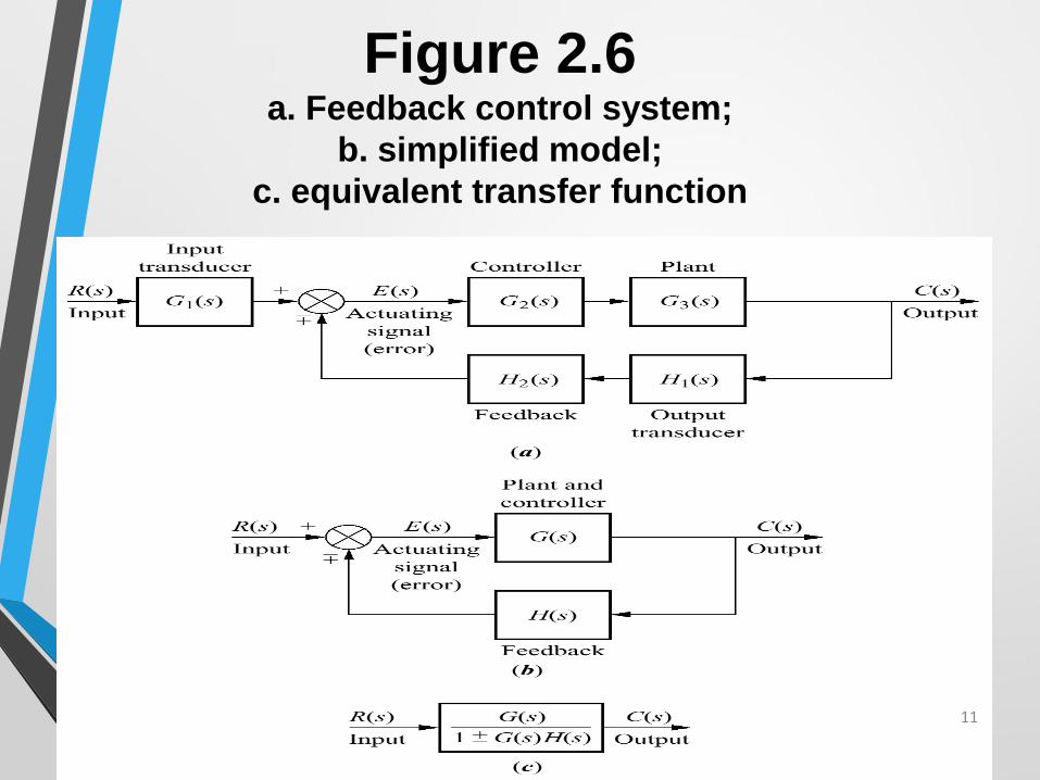
Figure 2.6 a. Feedback control system;
b. simplified model;
c. equivalent transfer function
11

Figure 2.7 Block diagram algebra for summing junctions—
a. to the left past a summing junction;
b. to the right past a summing junction
12

Figure 2.8 Block diagram
algebra for
pickoff points—
equivalent forms
for moving a
block
a. to the left past
a pickoff point;
b. to the right
past a pickoff
point 13

Figure 2.9
Block diagram for Example5.1
14

Figure 2.10 Steps in solving
Example 5.1:
a. collapse summing
junctions;
b. form equivalent
cascaded system
in the forward path
and equivalent
parallel system in the
feedback path;
c. form equivalent
feedback system and
multiply by cascaded G1(s)
15

Figure 2.11
Block diagram for
Example 5.2
16

17