Embed Size (px)
Citation preview

Blinker™ Division
Solar LED Solutions
BlinkerSign® LED SignSolar-Powered, 24/7 Operation
User Guide
BSIGN_24_7_Solar_guide_130411TAPCO • Traffic & Parking Control Company, Inc.
The Route To Safety, One Solution At A Time

NOTE: Used to notify you of information regarding installation, operation, programming or maintenance that is important but not hazard-related.
For technical support• Phone 866-753-6255• E-mail [email protected]
BlinkerSign® LED Sign Patents #6,943,698; #6,693,556
document use and statements
2TAPCO • Traffic & Parking Control Company, Inc. 5100 West Brown Deer Road, Brown Deer, WI 53223
CAUTIONIndicates a potentially hazardous situation which, if not avoided, could result in minor or moderate injury. It may also be used to alert against unsafe practices.
Follow the instructions inside the back cover to Register your Warranty.©2013 Traffic & Parking Control Company, Inc. (TAPCO) All rights reserved. This notice applies to all copyrighted material included with this product, including but not limited to this manual and software embodied within the product. This User Guide is intended for the sole use of the persons to whom it was provided. Any unauthorized distribution of the manual or dispersal of its contents is strictly forbidden. This manual may not be reproduced in whole or in part by any means whatsoever without the express written permission of TAPCO.
Warning, Caution and Note statementsWarning, Caution and Note statements are used throughout this manual to emphasize important and critical information. You must read these statements prior to assembly to help ensure safety and to prevent product damage. The statements are defined below.
WARNING
Indicates a potentially hazardous situation which, if not avoided, could result in death or serious injury.

Blinkersign® led sign parts list
Recommended Mounting HardwareMounting Hardware is sold separately because a BlinkerSign® can be mounted to a number of different types of posts, poles and brackets. Due to the depth of the sign, channels and spacers, you’ll need bolts that are a minimum of 1" longer than the thickness of the mounting post, pole or bracket. Posts, poles and sign mounting hardware are available from TAPCO or Distributor.
Recommended ToolsMulti-meter (Volt & Ohm)Drill motor (if drilling into support pole) Wrenches, Socket Set and Ratchet/Driver
Thank you for your purchase of TAPCO-made products!The solar-powered BlinkerSign® from TAPCO represents the latest technology in the field of LED-enhanced traffic signage, and is designed to provide you with years of trouble-free service.
Parts List (see Packing List for actual components)13-watt Solar PanelBlinkerSign® LED Sign with Support TubeController Assembly (shipped in Support Tube): AutoBright™ Control Module, NiMH Battery 110VAC Battery ChargerT100 Allen Wrench, Pin Type
NOTE: Please examine all parts before beginning assembly and installation. If anything is missing or damaged, contact TAPCO or your Authorized Distributor immediately.
TAPCO highly recommends that you use tamper-resistant hardware to mount BlinkerSign® LED signs. Use your own hardware, or order from TAPCO or your distributor.
3TAPCO • 800-236-0112 • www.tapconet.com BSIGN_24_7_Solar_guide_130411
CAUTIONALWAYS use Safety Glasses, Cut-proof Protective Gloves and OSHA-Approved Devices when handling, assembling and installing BlinkerSign® LED Signs!

Battery charging and testing
WARNING
NiMH batteries must be disposed of according to local code: DO NOT INCINERATE!
NOTE: Battery MUST be charged for 8 hours PRIOR to installation. If the battery is not fully charged prior to installation, your BlinkerSign® LED sign may not function properly.
Step 3 is used for troubleshooting purposes.
Step 3: Disconnect battery connector. Test the battery for VOLTAGE (VDC).Push 2 paper clips’ ends into MALE battery connector’s BLACK & RED leads, either into the pin holes or into the back side of the plug. Meter should read at least 4.8VDC. If less, see below.Test the battery for Continuity (OHMS Ω). Push 2 paper clips’ ends into MALE battery connector’s WHITE & BLACK leads, either into the pin holes or into the back side of the plug. Use meter on highest Ohm Ω scale to test across clips: if it displays ‘OL’ , replace with new battery.
Step 2Connect and charge the battery.Plug the battery’s connector (red, white and black wires) into charger connector. You’ll hear a distinct click when the connectors are fully seated. Plug the charger into a live 110-volt socket and charge for at least 8 hours. A full initial charge is essential for proper functioning. Proceed with assembly.
Step 1Remove the control module from the tube.An easy-to-use charger is enclosed in a box, bagged and taped to the back of the solar panel. Grasp the black plastic paddle and gently slide it out of the solar panel mounting tube. The battery and control module are attached to the paddle.
3
2
1
If less than 4.8VDC, proceed to ohms Ω test.
4TAPCO • Traffic & Parking Control Company, Inc. 5100 West Brown Deer Road, Brown Deer, WI 53223
sign location and alignment
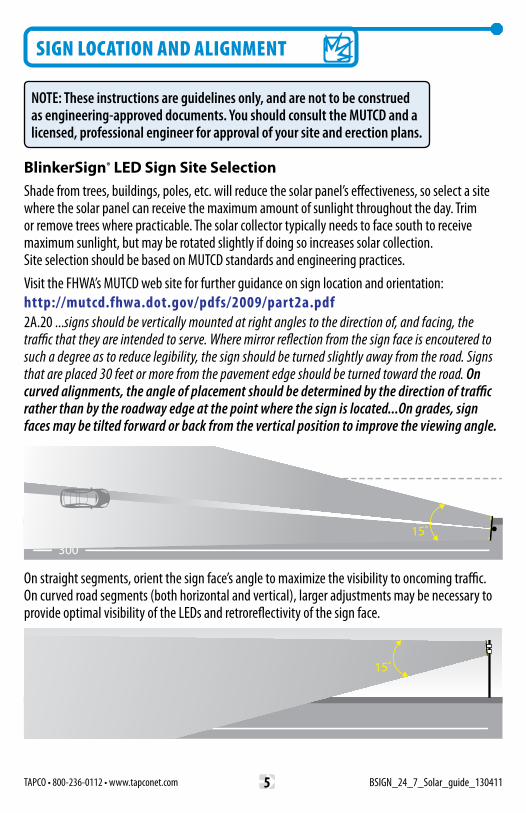
On straight segments, orient the sign face’s angle to maximize the visibility to oncoming traffic. On curved road segments (both horizontal and vertical), larger adjustments may be necessary to provide optimal visibility of the LEDs and retroreflectivity of the sign face.
SIDE VIEW
300’
VIEW FROM ABOVE
300’
SIDE VIEW
300’
VIEW FROM ABOVE
300’
BlinkerSign® LED Sign Site SelectionShade from trees, buildings, poles, etc. will reduce the solar panel’s effectiveness, so select a site where the solar panel can receive the maximum amount of sunlight throughout the day. Trim or remove trees where practicable. The solar collector typically needs to face south to receive maximum sunlight, but may be rotated slightly if doing so increases solar collection. Site selection should be based on MUTCD standards and engineering practices. Visit the FHWA’s MUTCD web site for further guidance on sign location and orientation: http://mutcd.fhwa.dot.gov/pdfs/2009/part2a.pdf2A.20 ...signs should be vertically mounted at right angles to the direction of, and facing, the traffic that they are intended to serve. Where mirror reflection from the sign face is encoutered to such a degree as to reduce legibility, the sign should be turned slightly away from the road. Signs that are placed 30 feet or more from the pavement edge should be turned toward the road. On curved alignments, the angle of placement should be determined by the direction of traffic rather than by the roadway edge at the point where the sign is located...On grades, sign faces may be tilted forward or back from the vertical position to improve the viewing angle.
NOTE: These instructions are guidelines only, and are not to be construed as engineering-approved documents. You should consult the MUTCD and a licensed, professional engineer for approval of your site and erection plans.
5TAPCO • 800-236-0112 • www.tapconet.com BSIGN_24_7_Solar_guide_130411

Step 3Connecting the control module to the battery. Attach the black/orange/red wire’s connector on the control module to the black/white/red wire’s connector on the battery. Then slide the paddle, battery and module fully into the solar mounting tube, leaving only the solar panel connector exposed for connection.
Step 2Connecting the control module to the LEDs.To simplify the assembly process for you, each set of connectors is unique so that only matched connectors can be used with each other. Use the two-wire connector (purple & green), connect the control module to the shielded cable’s LED connector from the tube.
Step 1Insert the components into the mounting tube.After fully charging the battery, begin the assembly process. On a suitable work surface, hold the SHIELDED LED lead to the side of the support tube (see inset with connector circled in red). Gently insert the paddle, battery and controller HALF WAY into the mounting tube, leaving the connectors exposed so you may attach them.
3
2
1
connecting the control module
NOTE: To simplify the assembly process, each set of connectors is unique so that only matched connectors can be used to mate with each other. You will hear a distinct click when the connectors are properly seated: pull gently to ensure they are locked together.
NOTE: Although you may connect and attach the solar panel at this time (steps 5 and 6), you may find it easier to wait until after the sign has been mounted onto the post or pole.
6TAPCO • Traffic & Parking Control Company, Inc. 5100 West Brown Deer Road, Brown Deer, WI 53223

Step 4Attaching the assembly to the mounting pole using anti-vandal hardware (not included).Anti-vandal sign-mounting hardware is highly recommended, and is available separately from TAPCO or Authorized Distributor. Attach the assembly to a post or signal pole by piercing the sign sheeting through the punched holes in the sign blank, and then securing it with bolts through the post and sign. To protect the sheeting, place a plastic washer between the sign sheeting and bolt head or nut. Optionally, attach the bolts to a z-bracket or banding bracket such as a flared leg bracket, as shown below at right. Attach the sign or bracket directly to the bolts: Do NOT band to the spacer channels as they will not support the sign. Read and heed WARNING panel above.
4
WARNINGDo NOT band to the spacer channels! Doing so could result in death or serious injury, as the spacer channels will not support the weight of the sign. Instead, run bolts through the sign and spacers so that the bolts support the weight of the sign. Assemblies that bolt through the sign are shown below at right.
Optional Mounting Assemblies: Banding and Z-BracketDO NOT BAND TO SPACER CHANNELS!
component/sign assemBly
WARNINGDo NOT handle signs and hardware without the use of cut-proof gloves! Sharp edges can cut skin and tissue, resulting in death or serious injury.
7TAPCO • 800-236-0112 • www.tapconet.com BSIGN_24_7_Solar_guide_130411

Step 5Connecting the control module to solar panel.The one remaining unattached connector will connect the control module to the solar panel. Connect the six-wire control module connector to the solar panel assembly connector, checking for proper contact by gently pulling at the connectors.
At this time the LEDs should be flashing. If they are, proceed to the next step of attaching the solar panel to its support tube. If they do not flash, fully charge the battery; proceed to the next page to troubleshoot the cause and take corrective action. Email or call TAPCO’s Technical Support if you have further issues. When operational, proceed to the next step.
Step 6Attaching the solar panel.The solar panel collector requires unobstructed sunlight. Ideally the solar panel will be facing the mid-day sun (south) at least three hours a day. If partially obscured, aim the collector panel so it will receive the maximum amount of solar energy. If severely obscured, consider trimming trees or relocating the solar panel into full sunlight. Loosen the solar panel’s set screws sufficiently to slide the solar panel assembly over the top of the sign’s solar panel support tube, and be sure to position the solar panel so it will face south when installed. Once aligned, tighten the set screws with the provided T100 Allen wrench. This completes the installation process.
5
6
connecting the solar panel
WARNING
Batteries must be disposed of according to your local code: DO NOT INCINERATE!
8TAPCO • Traffic & Parking Control Company, Inc. 5100 West Brown Deer Road, Brown Deer, WI 53223

Individual LED(s) Don’t
Flash
ALLLEDs Don’t Flash
Loose wiring
Inoperative LED(s)
Loose wires or connectors
Broken wires or connectors
Battery is not fully charged, or will no longer hold a charge at or above 4.8VDC: see Battery Testing illustrations on P.4
Insufficient Solar Charging
Contact TAPCO or TAPCO distributor for replacement part(s) or a repair authorization (RMA required).
Pull gently on each connector to ensure they are tight: if loose, press them together until you hear/feel them click.
Reconnect, or contact TAPCO or its distributor for replacement part(s).
Charge battery for 8 hours, then retest with Voltmeter (≥4.8VDC) or reconnect.
Disconnect battery. Push paper clip ends into MALE battery connector’s white & black leads. Use Ohmmeter on highest scale to test across clips: if it reads ‘OL’ , replace with new battery.
Align solar collector so it faces south, or relocate panel/assembly to full sun
If obstructed by trees, trim or remove them to allow more sunlight to reach the solar collector.
If obstructed by fixed object (such as building, mountain or hillside), rotate so collector receives the maximum amount of sunlight.
With collector in full sunlight, test solar leads with voltmeter to ensure a charging voltage of at least 5VDC.
SYMPTOM POSSIBLE CAUSES CORRECTIVE ACTION
trouBleshooting Technical support866-753-6255
9TAPCO • 800-236-0112 • www.tapconet.com BSIGN_24_7_Solar_guide_130411

Follow the instructions on the next page to Register your Warranty.Amended April 10, 2013
Traffic & Parking Control Company, Inc., (TAPCO), warrants to each purchaser of a BlinkerSign® 24/7 Solar LED Sign (Product) for other than personal, family or household use, that the Product will be free from defects in material and workmanship for a period of two (2) years after the date of original purchase.
TAPCO warrants accessories, service parts and components purchased separately to be free from defects in material and workmanship for a period of one (1) year after the date of original purchase. If within such warranty periods any part thereof is proved to TAPCO’s satisfaction to be defective, such part shall be repaired by TAPCO or its authorized distributor or, at TAPCO’s option, replaced f.o.b. TAPCO’s factory without charge, including labor costs at its standard rate incurred while repairing said Product.
TAPCO’s obligation hereunder shall be limited to such repair or replacement and shall be further considered upon TAPCO’s receiving written notice of any alleged defect and proof of original purchase within ten (10) days after its discovery and, at TAPCO’s option, the return of the allegedly defective part to TAPCO f.o.b. its factory or to its authorized distributor.
This warranty shall not apply to any parts not furnished by TAPCO as well as any damage caused by such parts, or to parts which shall have been repaired or altered by others than TAPCO so as, in TAPCO’s judgment, to adversely affect the same; or which shall have been subject to other than normal use or service, negligence, accident or improper installation, care or storage. TAPCO will not be responsible for any expense related to parts or labor which is unrelated to defects in material or workmanship of TAPCO Product, including but not limited to acts of God (Force majeure).The foregoing warranties are exclusive and in lieu of all other express and implied warranties.
TAPCO’s liability is limited expressly to the repair and replacement of defective parts as provided herein. TAPCO shall not be liable for any consequential, incidental, or contingent damages whatsoever, whether for breach of contract, breach of warranty, negligence or other tort, or on any strict liability theory.
John KugelPresidentTraffic & Parking Control Company, Inc.
warranty
10TAPCO • Traffic & Parking Control Company, Inc. 5100 West Brown Deer Road, Brown Deer, WI 53223
product record
warranty registration
Thank you for your purchase of TAPCO-made productsThe BlinkerSign® LED Sign Solar 24/7 Assembly from TAPCO represents the latest technology in the field of LED-enhanced traffic control, and is designed to provide you with years of trouble-free service. Please take a few moments to record the serial number(s) below, and keep this document in a safe place for future reference. This will be helpful if Warranty or Troubleshooting issues arise.
MODEL NAME: BlinkerSign® LED Sign, Solar 24/7 Assembly
SERIAL NUMBER(s):
DATE OF PURCHASE:
OPTIONS PURCHASED:
INSTALLATION LOCATION:
OTHER NOTES:
Your BlinkerSign® System Warranty can be registered on-line at:
www.tapconet.com/warrantyRecord the serial number(s) from the sign label(s) above, then log on.
Registration is simple and will take just a few moments of your time.
Thank you!
11TAPCO • 800-236-0112 • www.tapconet.com BSIGN_24_7_Solar_guide_130411

©2013, Traffic & Parking Control Company, Inc. (TAPCO)
US Patent Nos 6,943,698; 6,693,556; Other Patents Pending.
TAPCO Logo, BlinkerSign® and other trademarks are the intellectual property
of Traffic & Parking Control Company, Inc.
Document# BSIGN_24_7_Solar_guide_130411
REFERENCE # 13041029
TAPCO • Traffic & Parking Control Company, Inc. 5100 West Brown Deer Road, Brown Deer, WI 53223
INTERNET-ENABLED DEVICES
TAPCO’s BLINKLINK™ CLOUD-BASED
VIRTUAL PRIVATE NETWORK (VPN) GPS SATELLITES
BlinkerBeacon™ LED Beacons
Driver Feedback
RRFB &RRFB-XL™
BlinkerSign® LED Signs:Standard and Custom Legends
I.T.S. TRAFFIC DEVICES: MODEM-LINKED
• Dashboard View of Vital Stats: Cell Status; Battery Voltage & Temperature; Solar Voltage & Current • Historic Data by day, week, month or year • Zoom-in Geo Overview Map with pop-up views
• Device Status Reports • Programmable Text Alerts • Programmable Email Alerts
For technical support• Phone 866-753-6255 • E-mail [email protected]• Website www.tapconet.com
TAPCO’s BlinkLink™ is a web-based application that allows you to monitor and control your ITS products from any web-enabled device. Provides for text and/or email alerts to you and your staff. Contact TAPCO for details.