Embed Size (px)
Citation preview
Document
ARIS EDGE – BLE Sensors Demo – Application Note 28/09/2017
Doc: R16P10DTAN00, Rev: 1.0 1 of 14
ARIS EDGE
BLE Sensors Demo Application Note
All information contained in these materials, including products and product specifications, represents
information on the product at the time of publication and is subject to change by RELOC s.r.l. without notice.
Document
ARIS EDGE – BLE Sensors Demo – Application Note 28/09/2017
Doc: R16P10DTAN00, Rev: 1.0 2 of 14
Outline
Acronyms ........................................................................................................................................ 4
1. Introduction ................................................................................................................................. 5
2. System Requirements ................................................................................................................. 5
2.1 Hardware Requirements.................................................................................................... 5
2.2 Software Requirements ..................................................................................................... 5
2.3 Demo loading .................................................................................................................... 5
2.3.1 Synergy S1 programming ......................................................................................... 5
2.3.2 Silicon Labs MGM111 programming ........................................................................ 8
3. Design overview .......................................................................................................................... 9
3.1 Functionalities ................................................................................................................... 9
3.2 Architecture ....................................................................................................................... 9
3.3 Data sharing .................................................................................................................... 10
3.4 BLE interface ................................................................................................................... 11
3.4.1 S1 versus BLE communication ............................................................................... 12
3.4.2 BLE communication sequence ............................................................................... 13

Document
ARIS EDGE – BLE Sensors Demo – Application Note 28/09/2017
Doc: R16P10DTAN00, Rev: 1.0 3 of 14
Revisions
REVISION DATE DESCRIPTION STATUS AUTHOR REVISER
0.1 26/09/2017 Document created. draft C. Tagliaferri
1.0 28/09/2017 Document released release C. Tagliaferri A. Ricci
Disclaimer
All rights strictly reserved. Reproduction or issue to third parties in any form is not permitted without written
authorization from RELOC s.r.l.
RELOC s.r.l.
HEADQUARTERS
Via Borsari, 23/A 43126 – Parma (Italy)
Phone +39-0521-1759942
www.reloc.it
Document
ARIS EDGE – BLE Sensors Demo – Application Note 28/09/2017
Doc: R16P10DTAN00, Rev: 1.0 4 of 14
Acronyms
APP Mobile Application
BLE Bluetooth Low Energy
DOF Degrees of Freedom
IMU Inertial Measurement Unit
MCU Micro Controller Unit
S1 Renesas Synergy S1 MCU

Document
ARIS EDGE – BLE Sensors Demo – Application Note 28/09/2017
Doc: R16P10DTAN00, Rev: 1.0 5 of 14
1. Introduction
The ARIS EDGE “BLE Sensors” project demonstrates sensing and communication capabilities of
the ARIS EDGE board.
BLE Sensors demo code periodically reads values from the on-board sensors (i.e. 9-DOF IMU,
temperature, humidity and pressure and light sensing devices) and makes them available on the
BLE interface. Moreover, the same BLE interface allows for driving (turn on and off) the ARIS EDGE
LEDs. ARIS Tools mobile application is provided in order to interact with the ARIS EDGE board
through BLE interface.
The project is based on Renesas Synergy SSP 1.3.0 framework and the demo workspace is tested
using Renesas e2 studio (version 5.4.0.023).
In the following, the architecture and functionalities of the ARIS EDGE BLE Sensors demo are
detailed.
2. System Requirements
2.1 Hardware Requirements
ARIS EDGE board R1.1
Mini-USB cable
J-Link programmer used for the MGM111 firmware loading (sensors demo firmware is
preloaded at production so it could not be necessary).
Android or iOS smartphone with the “ARIS Tools” APP.
2.2 Software Requirements
The project has been developed with:
Renesas Synergy SSP 1.3.0 framework
e2studio 5.4.0.023
BGtool 2.3.3-2346 (for the MGM111)
2.3 Demo loading
In order to execute the ARIS Sensors demo, both Synergy S1 microcontroller and Silicon Labs
MGM111 system-on-chip should be programmed.
2.3.1 Synergy S1 programming
Synergy S1 programming could be performed exploiting e2studio IDE and the ARIS EDGE on-board
J-Link debugger.
Document
ARIS EDGE – BLE Sensors Demo – Application Note 28/09/2017
Doc: R16P10DTAN00, Rev: 1.0 6 of 14
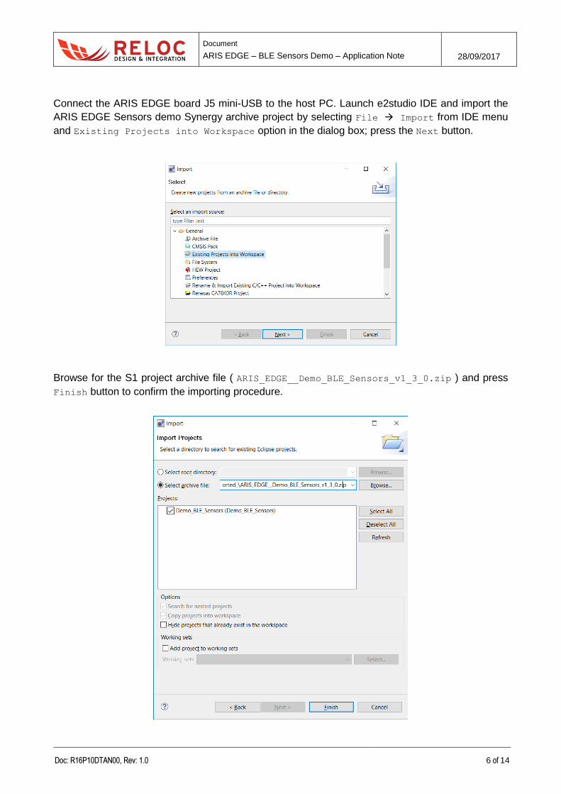
Connect the ARIS EDGE board J5 mini-USB to the host PC. Launch e2studio IDE and import the
ARIS EDGE Sensors demo Synergy archive project by selecting File Import from IDE menu
and Existing Projects into Workspace option in the dialog box; press the Next button.
Browse for the S1 project archive file ( ARIS_EDGE__Demo_BLE_Sensors_v1_3_0.zip ) and press
Finish button to confirm the importing procedure.
Document
ARIS EDGE – BLE Sensors Demo – Application Note 28/09/2017
Doc: R16P10DTAN00, Rev: 1.0 7 of 14
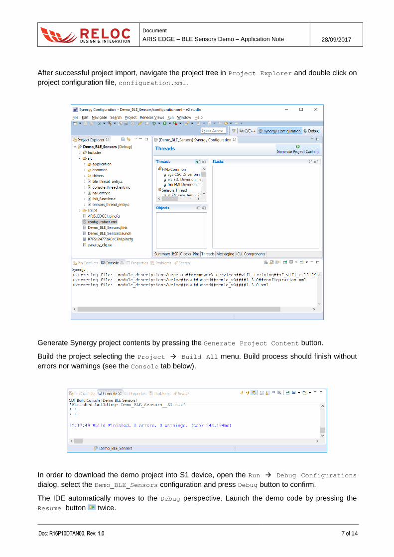
After successful project import, navigate the project tree in Project Explorer and double click on
project configuration file, configuration.xml.
Generate Synergy project contents by pressing the Generate Project Content button.
Build the project selecting the Project Build All menu. Build process should finish without
errors nor warnings (see the Console tab below).
In order to download the demo project into S1 device, open the Run Debug Configurations
dialog, select the Demo_BLE_Sensors configuration and press Debug button to confirm.
The IDE automatically moves to the Debug perspective. Launch the demo code by pressing the
Resume button twice.
Document
ARIS EDGE – BLE Sensors Demo – Application Note 28/09/2017
Doc: R16P10DTAN00, Rev: 1.0 8 of 14
2.3.2 Silicon Labs MGM111 programming
ARIS Sensors demo requires that “Demo_BLE_Sensors__MGM.bin” binary file is loaded into
MGM111 device.
Please refer to “ARIS EDGE User Guide” – section 3.3 for the detailed procedure.
Document
ARIS EDGE – BLE Sensors Demo – Application Note 28/09/2017
Doc: R16P10DTAN00, Rev: 1.0 9 of 14
3. Design overview
3.1 Functionalities
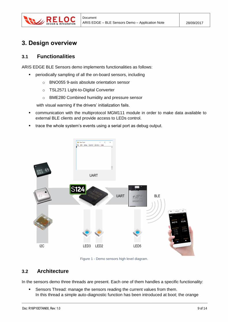
ARIS EDGE BLE Sensors demo implements functionalities as follows:
periodically sampling of all the on-board sensors, including
o BNO055 9-axis absolute orientation sensor
o TSL2571 Light-to-Digital Converter
o BME280 Combined humidity and pressure sensor
with visual warning if the drivers’ initialization fails.
communication with the multiprotocol MGM111 module in order to make data available to
external BLE clients and provide access to LEDs control.
trace the whole system’s events using a serial port as debug output.
Figure 1 - Demo sensors high level diagram.
3.2 Architecture
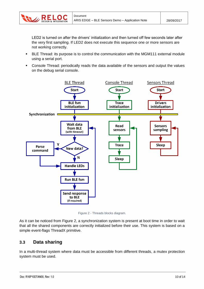
In the sensors demo three threads are present. Each one of them handles a specific functionality:
Sensors Thread: manage the sensors reading the current values from them.
In this thread a simple auto-diagnostic function has been introduced at boot; the orange
I2C LED3 LED2 LED5
UART
UART
BLE
Document
ARIS EDGE – BLE Sensors Demo – Application Note 28/09/2017
Doc: R16P10DTAN00, Rev: 1.0 10 of 14
LED2 is turned on after the drivers’ initialization and then turned off few seconds later after
the very first sampling. If LED2 does not execute this sequence one or more sensors are
not working correctly.
BLE Thread: its purpose is to control the communication with the MGM111 external module
using a serial port.
Console Thread: periodically reads the data available of the sensors and output the values
on the debug serial console.
Figure 2 - Threads blocks diagram.
As it can be noticed from Figure 2, a synchronization system is present at boot time in order to wait
that all the shared components are correctly initialized before their use. This system is based on a
simple event-flags ThreadX primitive.
3.3 Data sharing
In a multi-thread system where data must be accessible from different threads, a mutex protection
system must be used.
Document
ARIS EDGE – BLE Sensors Demo – Application Note 28/09/2017
Doc: R16P10DTAN00, Rev: 1.0 11 of 14
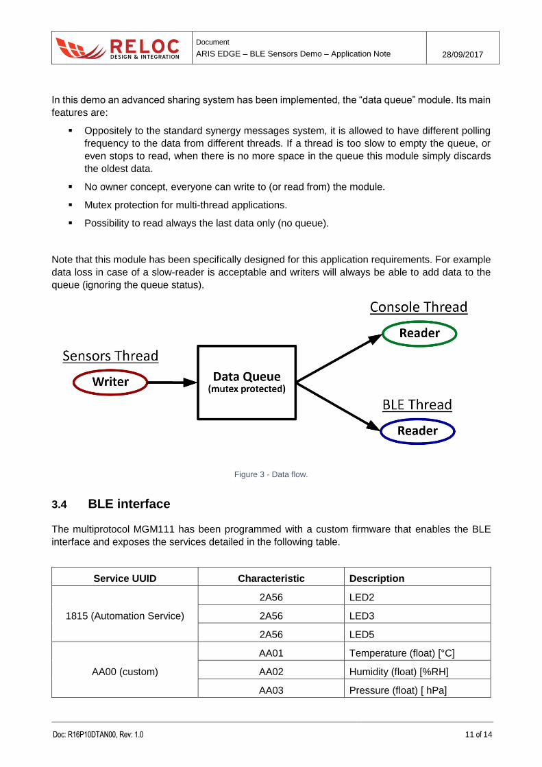
In this demo an advanced sharing system has been implemented, the “data queue” module. Its main
features are:
Oppositely to the standard synergy messages system, it is allowed to have different polling
frequency to the data from different threads. If a thread is too slow to empty the queue, or
even stops to read, when there is no more space in the queue this module simply discards
the oldest data.
No owner concept, everyone can write to (or read from) the module.
Mutex protection for multi-thread applications.
Possibility to read always the last data only (no queue).
Note that this module has been specifically designed for this application requirements. For example
data loss in case of a slow-reader is acceptable and writers will always be able to add data to the
queue (ignoring the queue status).
Figure 3 - Data flow.
3.4 BLE interface
The multiprotocol MGM111 has been programmed with a custom firmware that enables the BLE
interface and exposes the services detailed in the following table.
Service UUID Characteristic Description
1815 (Automation Service)
2A56 LED2
2A56 LED3
2A56 LED5
AA00 (custom)
AA01 Temperature (float) [°C]
AA02 Humidity (float) [%RH]
AA03 Pressure (float) [ hPa]
Document
ARIS EDGE – BLE Sensors Demo – Application Note 28/09/2017
Doc: R16P10DTAN00, Rev: 1.0 12 of 14
AA04 Illuminance (float) [lux]
AA10 (custom)
AA11 Accelerometer X (float) [mg]
AA12 Accelerometer Y (float) [mg]
AA13 Accelerometer Z (float) [mg]
AA20 (custom)
AA21 Gyro X (float) [dps]
AA22 Gyro Y (float) [dps]
AA23 Gyro Z (float) [dps]
AA30 (custom)
AA31 Magnetometer X (float) [uT]
AA32 Magnetometer Y (float) [uT]
AA33 Magnetometer Z (float) [uT]
Apart of the LED service, clients can subscribe to the characteristics so that they will be automatically
notified when the values change. This is the mode used from the mobile APP.
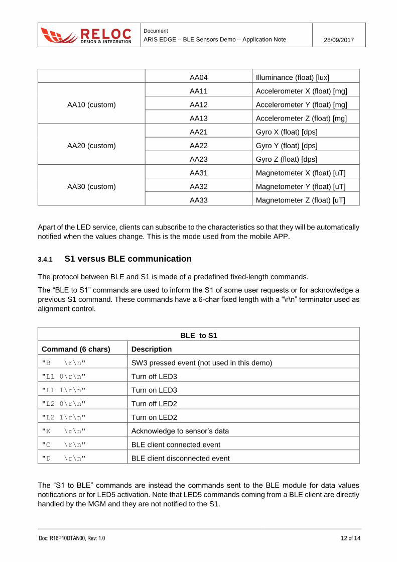
3.4.1 S1 versus BLE communication
The protocol between BLE and S1 is made of a predefined fixed-length commands.
The “BLE to S1” commands are used to inform the S1 of some user requests or for acknowledge a
previous S1 command. These commands have a 6-char fixed length with a “\r\n” terminator used as
alignment control.
BLE to S1
Command (6 chars) Description
"B \r\n" SW3 pressed event (not used in this demo)
"L1 0\r\n" Turn off LED3
"L1 1\r\n" Turn on LED3
"L2 0\r\n" Turn off LED2
"L2 1\r\n" Turn on LED2
"K \r\n" Acknowledge to sensor’s data
"C \r\n" BLE client connected event
"D \r\n" BLE client disconnected event
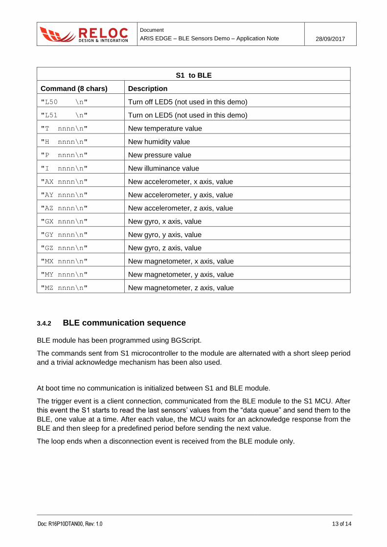
The “S1 to BLE” commands are instead the commands sent to the BLE module for data values
notifications or for LED5 activation. Note that LED5 commands coming from a BLE client are directly
handled by the MGM and they are not notified to the S1.
Document
ARIS EDGE – BLE Sensors Demo – Application Note 28/09/2017
Doc: R16P10DTAN00, Rev: 1.0 13 of 14
S1 to BLE
Command (8 chars) Description
"L50 \n" Turn off LED5 (not used in this demo)
"L51 \n" Turn on LED5 (not used in this demo)
"T nnnn\n" New temperature value
"H nnnn\n" New humidity value
"P nnnn\n" New pressure value
"I nnnn\n" New illuminance value
"AX nnnn\n" New accelerometer, x axis, value
"AY nnnn\n" New accelerometer, y axis, value
"AZ nnnn\n" New accelerometer, z axis, value
"GX nnnn\n" New gyro, x axis, value
"GY nnnn\n" New gyro, y axis, value
"GZ nnnn\n" New gyro, z axis, value
"MX nnnn\n" New magnetometer, x axis, value
"MY nnnn\n" New magnetometer, y axis, value
"MZ nnnn\n" New magnetometer, z axis, value
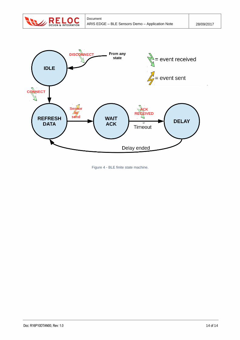
3.4.2 BLE communication sequence
BLE module has been programmed using BGScript.
The commands sent from S1 microcontroller to the module are alternated with a short sleep period
and a trivial acknowledge mechanism has been also used.
At boot time no communication is initialized between S1 and BLE module.
The trigger event is a client connection, communicated from the BLE module to the S1 MCU. After
this event the S1 starts to read the last sensors’ values from the “data queue” and send them to the
BLE, one value at a time. After each value, the MCU waits for an acknowledge response from the
BLE and then sleep for a predefined period before sending the next value.
The loop ends when a disconnection event is received from the BLE module only.
Document
ARIS EDGE – BLE Sensors Demo – Application Note 28/09/2017
Doc: R16P10DTAN00, Rev: 1.0 14 of 14
Figure 4 - BLE finite state machine.