Embed Size (px)
Citation preview

Page 1
BLD226683
Revit for MEP Fabrication – The Process from Start to Finish Bryan Strecker MB BIM Solutions Daniel McCloskey MB BIM Solutions
Description
This class will teach MEP subcontractor attendees how to use Revit for MEP modeling, coordination, and fabrication. We will start with setting up Revit families and Fabrication Parts content, go into modeling strategies, discuss add-ins, and finish with producing coordination drawings and spooling drawings. Having developed this service from scratch, this class will offer a unique perspective on the process from start to finish. This class aims to demonstrate the utilization of both Revit and Navisworks Manage in developing these construction drawings for a simpler workflow in the field, as well as a more cohesive coordination process, discussing modeling strategies utilizing various Revit add-ins to ensure efficient workflow, reducing rework in the coordination process. We will also discuss utilizing Fabrication CADmep in the development of custom Revit Fabrication Parts. Finally, we will learn about the various types of drawings that are utilized most readily in the field.
Speaker(s)
Bryan Strecker received his master's degree in Mechanical Engineering from the University of Kansas in Lawrence, KS in December of 2012. Bryan then moved to Colorado and spent three years in the Oil and Gas industry utilizing AutoCAD Plant 3D and CADWorx, then making the switch to the AEC industry in 2016. In his time at MB BIM Solutions he has worked as a consultant, utilizing Revit in a variety of Structural and MEP projects and developing the Revit MEP modeling services. He has explored the requirements of MEP subcontractors in an effort
Learning Objectives
• Utilize Revit MEP Fabrication parts and assemblies to create various shop drawings to be utilized in the field.
• Understand workflow strategies to use Revit throughout the entire MEP subcontractor process.
• Demonstrate the use of Fabrication CADmep to develop custom Revit Fabrication Parts for each project.
• Learn about 3rd Party Revit Add-Ins that can facilitate faster workflow in creating accurate 3D models.

Page 2
to develop more sophisticated shop drawings for use in the field. He has also worked as the lead in Navisworks clash coordination, giving a unique perspective in the project process.
Dan McCloskey received his bachelor's degree in civil engineering from the University of Illinois at Champaign-Urbana. After spending 2 years designing bridges for URS Corporation, Dan attended Purdue University, where he obtained a master’s degree in structural engineering. Dan then moved to Denver, Colorado, where he worked as a structural design engineer and then structural project engineer for S.A. Miro. During his 5 years with Miro, Dan became an in-house expert in Revit Structure, and he helped develop BIM-based structural detailing services. In 2011, Dan co-founded MB BIM Solutions as a BIM-focused consultancy that provides construction-level modeling of structural systems and components for its clients. Dan is active in the Denver-area BIM community with Rocky Mountain Building Information Society, has taught several classes at Autodesk University, has been published in AUGIWorld magazine, is a Revit Beta contributor, and is also a Revit Gunslinger participant.

Page 3
Goals for the Project: Shop Drawings
The overall goal of our projects has been to produce drawings that can be used in the field to install fully coordinated MEP systems. Thus far, we have had our focus on Plumbing and Duct, as well as Mechanical Pipe for the various types of duct systems. We would like to eventually get into fire protection and electrical, such that we can facilitate the entire coordination process in one place. However, we are still learning and haven’t dove into this quite yet. The various shop drawings we have produced thus far include piping layout plans, hanger plans, slab penetration plans, 3D isometrics, and spooling drawings. The piping layout plans are fairly straight-forward, showing the locations of pipe or duct with respect to grids, also calling out the service and elevation. These are the main drawings used to lay out where everything is routed. This drawing works well because it closely mimics the design drawings, so the installers are familiar with the format and can seamlessly begin using the drawings. One of the drawbacks is this drawing can get quickly cluttered as it tries to dictate everything there is to know about the pipe. With condensed systems, this drawing needs the aide of other drawings to fully explain the routing.
Figure 1: A portion of a domestic water piping layout plan.

Page 4
Hanger plans and slab penetration plans are used in their most basic form to lay out exactly where hangers and slab penetrations are located. The hanger drawings give elevations for either centerline or bottom of pipe (depending on what the field would like to see), as well as locations in plan view for where the sleeves and hangers are with respect to grid. These drawings also give the size of the lines in question. Along with the drawings themselves, we have also begun exporting points for hanger and sleeve locations to be used with a Trimble system. A quick point layout drawing gives a reference for which points are referred to and where they are located in plan.
Figure 2: A portion of a duct hanger layout plan.
Although these drawings give the whole picture for what should be installed, we have found that also providing a 3D Isometric view of the entire system gives the installers a general picture of where things are routed, why they offset in different places, and how the system should look once installed. We have been told on a couple occasions that this drawing is the most helpful for wrapping their heads around the dictated routing. Given that this is the easiest drawing to produce as it requires no annotation, it was a simple add to our list of drawings. Finally, we have recently begun producing spool drawings for complex systems that want to be prefabricated. These are produced using assemblies and material takeoffs, but we have found an easier way to produce these using a Victaulic add-in which we will discuss in a

Page 5
later section. Using this add-in we can quickly produce spooling drawings for entire systems, making prefabrication possible and simple. Of course, these drawings cannot be useful without a full 3D coordination process. We utilize Navisworks Manage to facilitate this coordination, performing simple clash detection twice a week. More on this subject in a later section. However, it is important to note that we are consistently shooting for a LOD 300 minimum, while incorporating aspects of LOD 400. We have been using the term LOD 350 to essentially describe LOD 300 with hangers and clearance zones added in. The next section describes how we attain LOD 350 using Revit Fabrication Parts.
Revit Implementation Having started in structural BIM modeling our team was already very familiar with how Revit works in general. Furthermore, the architectural, structural and MEP design models we receive at the start of a project are almost always in Revit. Thus, the natural choice for modeling the MEP systems for coordination is to use the Revit MEP systems. However, Revit MEP systems are still in development, gaining new features with every release. Thus, over time, the methodologies may change what and how we model these systems. The design systems in Revit are very useful for sizing the systems initially, getting the basic layout of the pipe runs, and giving a general idea of what should be placed where. However, the pipe and duct produced do not necessarily represent what is going to be built in the field. For example, these design parts do not include flanges for duct, or proper sizes for valves and fittings. These of course can be developed using Revit families, but Revit has produced a much quicker option: Fabrication Parts. The out-of-the-box fabrication parts provide just about everything you will need to model entire systems of plumbing and duct, but this time around with much greater attention to detail. With this, attaining a higher LOD is much simpler. Modifications to these fabrication parts can be attained with the use of Fabrication CADmep, a topic we will discuss in a later section. With Fabrication Parts, we can route systems quickly and easily by snapping pieces together like Legos. Furthermore, adding hangers is now possible and very easy (though it has been made even easier by an add-in by DeWALT). However, fabrication parts do have their drawbacks.

Page 6
Figure 3: The Fabrication Parts panel with cast iron fittings displayed.
Design Parts vs Fabrication Parts: Pros and Cons As stated before, Fabrication Parts have their drawbacks. For example, they cannot perform any calculations like the Revit design families can. It is worth noting that design families are built for MEP engineers, whereas fabrication parts are built more for MEP contractors. Furthermore, Revit does not natively have a way to create new custom Fabrication Parts. It must rely on Fabrication CADmep to add any new items to the list.
Thus, it may be useful to start using design parts, then convert to fabrication parts once coordination has started. This allows one to gain the benefits of both types. There is a caveat, though. What is allowable in design parts is not necessarily buildable in the real world. For example, a copper elbow of 80 degrees is possible to implement in design parts, but when trying to convert to a fabrication part, Revit will not have an option available that matches, so it simply won’t convert the family to a fabrication part. Furthermore, conversion of valves is a bit tricky, with most valves not having a counterpart. Thus, the conversion process is rarely clean and will require some checking and QC to make sure everything is what it should be.
One final drawback of Fabrication Parts is their lack of useful parameters. One must create shared parameters that relay information back to the user for use in tags and annotation. The next section will discuss this process.

Page 7
Achieving the Most from your Model As stated before, one difficulty of using Fabrication Parts is a lack of useful parameters for tagging. Fabrication Parts are not Revit families, and thus adding parameters is a bit more involved. The easiest way we have found to add parameters to items is to add shared parameters to the project, applying them to the fabrication parts in question. This process is quite simple and will apply to all of your fabrication pipework, duct, or whatever category you choose. However, if you still have Revit families implemented in your system, you will need separate tags for the Revit families and the Fabrication Parts. Furthermore, it may be useful to utilize multiple tags for different pieces. For example, in our hanger drawings, we call out three things for each hanger: a hanger tag number, the centerline of the pipe, and the pipe size. This is accomplished with one tag for the hanger tag number itself, then another tag for the pipe at the support point. Unfortunately, this requires essentially tagging the same thing twice. More development is underway to see if we can reduce this to just one tag. Another example has to do with filters. In the out-of-the-box Mechanical template, there are several filters already created that act upon the Revit families based on system (Domestic, Hydronic, Vent, Mechanical Supply, etc.). These filters filter by the System Classification of the family in question. Thus, these will not work with Fabrication Parts, which do not have a system classification. These filters must be replicated utilizing the very limited parameters natively available for Fabrication Parts, or using shared parameters as described above. For simplicity, we have been using the “Comments” parameter for these filters. However, this requires filling out the comments for every part in the system. This system of filling out comments for all parts can get very tedious and repetitive, but it is the safest way we have found to be able to filter these parts out. Furthermore, if anything else is wanting to be tagged, one may have to create a number of shared parameters in order to properly filter what you want.

Page 8
The Project Process
A typical project workflow begins with receiving Architectural and Structural models and drawings from the design team. These are usually in Revit format, thus giving a great head start for the project and a background for us to work with. If a Revit model of the MEP systems is available from the design team, this is also a huge head start, though this is not always available. The first step in the project is to either copy in the MEP model, or to build this MEP model based on the design drawings. This is by far the most laborious step as it takes careful consideration to ensure consistency across the project. For example, if copying in the MEP model from the design team, this will typically be using Revit families. Per the previous section, the Revit families are not going to represent a LOD 350 design, so the entire model must be converted to Fabrication Parts. If some families don’t have a direct Fabrication counterpart, care must be taken to adjust the model such that fabrication parts can be used for all pipe, duct, and fittings. When converting using the “Design to Fabrication” command, if the family doesn’t have a counterpart, it may simply delete the fitting. A great example of this is an elbow that is at a different angle than 90, 45, or whatever else is available in Fabrication Parts. Furthermore, if any custom Fabrication Parts are being utilized, the parts must be added manually. It may be useful to leave some items as Revit Families, although this may make drawing creation more difficult with respect to how things look (line weights, for example, will be different between the two types). The next step in the project process implements 3D coordination, another aspect of the project we typically control. The following sections will discuss this coordination process.
Figure 4: The Navisworks Clash Detective, home to many BIM coordinators.

Page 9
Coordination Process The coordination process involves all the MEP subcontractors, as well as the general contractor, and the coordinator. We often take the role as the 3D coordinator as well as the Mechanical and Plumbing subcontractor. Thus, the coordination process is often expedited as we control more than one aspect. As the coordinator, we perform a structural and architectural model QC, making sure the model matches the drawings. This involves checking the ceilings, walls, and doors for their location, size, and makeup. Some of the common discrepancies we find are ceiling thicknesses being inaccurate, or at the wrong elevation, walls being inaccurately located, and doors being the wrong size. These are quick and easy fixes that make the coordination process go much smoother. One final aspect of our QC is an initial check on the systems and how they fit in the proposed ceiling space. One item that is often overlooked is insulation on duct and pipe. We have found on a few different projects that the duct will fit just fine in the ceiling space when it is uninsulated, but once the insulation is added (up to 2” on each side), the duct no longer fits in any fashion. If these types of things are caught early on, it is much easier to adjust the architecture or the duct to make things work, which would otherwise be a very costly and time-consuming fix in the field.
Navisworks Coordination The goal of Navisworks coordination is to produce a clash-free model for all trades,
allowing for seamless installation in the field requiring little to no coordination at all. In order to attain a truly clash-free model, we must include all of the MEP systems, their clearance zones, their hangers, and anything else that may be installed in the field. Furthermore, we do quite a bit of supplemental modeling, adding in things like king studs and cold form kickers. These items are often not included in the design models, but will drastically affect the coordination process. For example, if a duct or pipe is running over the top of a door, we need to ensure it does not clash with the king studs or jamb studs as these cannot move and thus the clash must be mitigated ahead of time.
It is at this point that the level of detail prescribed for the project comes into play. LOD 300 does not include hangers, and as such, does not include everything that could cause clashes. Likewise, it doesn’t include clearance zones, so as we discussed earlier, the models must be a bit more developed than this. LOD 400 isn’t absolutely necessary as long as certain key aspects are included in the model.
The final aspect of our coordination process that we feel really speeds things along is the implementation of two coordination meetings per week. Although this cuts down on the amount of time the subcontractors have between meetings, we have found that it doesn’t cut down on the productivity overall. In fact, we have found that it speeds things up substantially, as without meetings there is a tendency to become complacent with the model and not work for a couple days. Setting up the project from the beginning to have two meetings allows for a much more responsive team with stronger collaboration. However, we do not do full clash coordination with grouping and sorting of clashes in both meetings. We save this for the second meeting in the week, whereas the first meeting takes a look at the general nature of the model, looking in particular for high density or congested areas. Even this simple check through the model with all clashes grouped together gives a great picture of where the most work is needed. Then, attention can be given to these areas such that the number of clashes reviewed in the second

Page 10
meeting are drastically reduced. The first meeting should take on the order of thirty minutes, with the second meeting taking upwards of an hour.
Overall, this coordination ultimately depends on the subcontractors and how well they work together, but some of these tips and tricks have helped us to expedite the process. Now that we have discussed the project and what we want to produce, I would like to use the next sections to describe some tools we have used in our modeling efforts that have helped us increase our level of design, as well as to speed up the modeling process.
Figure 5: A screenshot showing clashes between plumbing and fire protection in Navisworks Manage.

Page 11
Fabrication CADmep
Fabrication CADmep has been in use for years as an MEP modeling program, and has many uses for creating all of the designs for MEP systems. However, we will not be using this program for it’s original intended use. We will be using it to make our Fabrication Parts in Revit more powerful, controllable, and useful overall. Although the native Revit Fabrication Parts have just about everything one could need for modeling their entire systems, it does not yet have the ability to add new parts, add new insulation systems, or use many real-world parts that are available off-the-shelf. The Fabrication Parts in Revit are rather generic in nature, following code for sizing fittings and accessories. We want more out of our Revit models, though, so we will have to turn to Fabrication CADmep to accomplish our goals of a LOD 350 design.
The next few sections go over how to use Fabrication CADmep to create insulation specifications for certain systems, as well as to add new Parts to our catalog. These steps are not necessarily difficult to perform, but to a Revit user, these can be completely foreign.
How To: Create Insulation Specs The native Revit insulation specs for fabrication parts are relatively limited in their nature, only allowing for certain insulation thicknesses and no ability to add new insulation thicknesses like the design parts can. With design parts, one simply adds insulation to a piping or duct system, adjusting the thickness and material as desired. This section will detail how to add a new insulation specification to your fabrication parts catalog. From here, it is a simple selection of the customized system as a parameter to apply the insulation. The first step is to open Fabrication CADmep, then select which configuration you would like to edit. We will be using the Revit MEP Imperial Content V2.1, available natively in Revit 2018. Next we will edit the global database by clicking the button that looks like a little open book. From here we can edit a number of things in our database, and ultimately our Revit Fabrication Parts configuration. What we are looking for at the moment, though, is to select “Fittings,” then select “Insulation Specifications” in the side bar. Here, we can look at the insulation specifications we have available natively, as well as any ones that we have created. Currently the specification selected is called “Acoustic Liner 1”.” The easiest way to create a new specification is, as is typical with anything in Revit, to duplicate another specification and modify it to our liking.

Page 12
Figure 6: The Fabrication CADmep Insulation Material Properties dialogue where we edit and create new
insulation specifications.
Next we will need to select which insulation specification we would like to use as a starting point for our new specification. Here, I have selected the General Insulation under Piping, version 1. This will allow us to create a new piping insulation spec. You can do the same thing for duct, but for this exercise we will stick with pipe. Next, we will select “New” and the program will ask us if we would like to make a copy of the selected insulation specification. Click “Yes” to continue. The next window that pops up will ask you to name the spec. Name the specification some thing that makes sense for what you will be using this for. For example, “Domestic Cold Water”. We will select the Pipework group if it is not already, and give it an abbreviation. Here we can also select where the insulation will be placed, whether it is a wrap on the outside of the pipe or a liner. We will select “Outside” for now. If you would like to alter the connections or seams, this is the place to do so, though we will skip this for now. Once you have your name, group, and location set, click OK. These can always be changed by clicking “Properties” in the Database dialogue. The next step is to edit our database such that we get the right insulation thickness for different sizes of pipe. This can be as simple or complex as your system requires. For this exercise, I have chosen to make a very simple specification, only giving two different thicknesses of insulation. Double click one of the entries shown to edit it. Note that the way it works is you set what size of pipe, less than or equal to, that we want to edit. For this example, I will set that all pipe 2” and smaller gets ½” insulation, whereas anything larger than that gets 1” of insulation. Make sure the insulation type is correct for what you are using it for. We will select Phenolic ½” and 1”. Once you have all of your sizes and insulation thicknesses set, simply click OK and your configuration will be saved, ready to use in Revit. A later section will detail how to apply these in your Revit configuration by simply reloading.

Page 13
How To: Download Parts from the Web Similar to Revit Families, many manufacturers take the initiative to create fabrication parts and supply them online for anyone to download and use. This section will detail how to download these parts and add them to our usable catalog. Thus, the first step is to download the parts we would like to use. Next, we add them to our service as required. Finally, we save these to our configuration and reload them in Revit. As stated, the first step is to find new parts you would like to add to our service. One can create custom parts from scratch, but MB BIM has yet to get into this. What we have done thus far is to simply download new parts from manufacturers, or to copy and modify an existing part. Fabrication CADmep has a very powerful command that allows the user to search for parts from manufacturers that have already been created. Engineers are inherently lazy, thus this is our first choice for adding parts to our catalog. This command is simply “DOWNLOADCONTENT”. In Fabrication CADmep, type in the command and hit enter. The dialogue that appears will prompt you to search for just about anything we could want. We will start by adding a couple fittings to our piping specs. You can filter based on a number of parameters, including metric vs imperial, manufacturer, templates, and OEM products and services. We will select our manufacturer, and select Imperial for our units. You can also add keywords or a description to further filter this list down as it can be quite daunting at first. We will add the word “Copper” to our keywords so we can find all the copper fittings available. Then click Search and the program will do a search for everything that fits this category. Note that different materials surface for us to choose from. We want Mueller fittings, so we will click the green plus sign to add these to our download list. Once we select all of the components we would like to download, we simply click “Download” in the bottom right corner. A dialogue will pop up showing which objects have been installed and updated. Click OK. You now have a new service under the dropdown that has all of these fittings available for use in Fabrication CADmep. The next steps involve bringing these new fittings into our other services, then into Revit for use with our Fabrication Parts. This next section details how to bring these in, as well as to modify these so they connect properly with the rest of our parts.

Page 14
Figure 7: The DOWNLOADCONTENT dialogue box.
Applying your new Parts in Revit
The first step in bringing these new valves into Revit is to add them to a specific service we will be using in Revit. At the top of your screen, click the service dropdown and select the service you would like to add the valves to. For our example, we will select “Copper Soldered”. Next, we click Edit Service Database, and another dialogue pops up to have us select what service we would like to edit. Since we already selected Copper Soldered, this is selected in the dropdown. If you need to edit multiple services, you can easily switch between them here. We will next select “Service Information” to edit the service. Another dialogue pops up. At the top, we can edit the name of the service, and select which group it will show up under. On the left, we have the option to select where to pull the parts from, and on the right we have our full list of fittings, valves, etc, that we would have available in Copper Soldered. On the left, select “Other Templates” to find the Mueller template we just downloaded. We select Soldered, and all of our
Page 15
new fitting buttons appear. From here, it is a simple drag and drop to add these new fittings to our current service.
Once you have added the components to your service, we simply click OK, and Fabrication CADmep saves our configuration. From here, there are a number of steps to bring these items into Revit. First, we must make sure the fittings are going to connect properly with the rest of our service, as the connector is not necessarily the same type we want.
On the left, you will see your parts, including your newly downloaded cap. We want to edit the connector so it works with the rest of the fabrication parts in this service, so we right-click and select Edit, then the part. A dialogue pops up that will allow you to edit several parameters, including the size and connectors which are what we are looking for here. The view of the part will show you in detail what each abbreviated part is called. We want to edit C1 connector. We click “Other” and on the right we have the connector type. Click the dropdown and look for “Copper Soldered Cup” as this most closely resembles what we are using in this service. Note that this will change the connector for all sizes, so we do not have to worry about changing this for every size we want available.
Figure 8: The Edit Part dialogue box in Fabrication CADmep where we will edit the connectors.
Here is also where we can edit the dimensions of the component to more closely
resemble something in the real world. To do this, click the Edit Product List button. A spreadsheet dialogue pops up wherein we can change the dimensions for the part. Note that

Page 16
here we can also add a new size to our list of available sizes. For more complex components, this list is much more involved. For now, we’ll leave this as is.
Figure 9: The Edit Product List dialogue box in Fabrication CADmep where we will edit the fitting
dimensions.
Once your component is edited per your specifications, we now want to make sure we
can add these to our systems in Revit. Now we go back to Revit. In the bottom of our Fabrication Parts panel, click “Settings…”. In the dialogue that pops up, make sure your configuration is the correct one, then click “Reload Configuration.” From here, select which services you would like to use in your project and move them over to the Loaded Services list. You now have a new component added to your service!

Page 17
Figure 10: The Fabrication Settings dialogue box in Revit where we select our usable fabrication services.

Page 18
Revit Add-Ins: Your Best Friend
Throughout this presentation I have mentioned a couple add-ins for Revit that drastically speed up the modeling and coordination process. These include DeWALT’s Hangerworks, and Victaulic’s Pipe Tools. Each of these is relatively inexpensive and easy to use. The next few sections will go into detail about how the add-ins work, as well as how to utilize them to our benefit. DeWALT Hangerworks’ main function is to add hangers to your model systematically and according to rules the user will set. Victaulic’s Pipe Tools has a number of functions that are incredibly useful, but the main function we will be discussing is how to quickly and easily create spooling drawings.
DeWALT Hangerworks DeWALT’s Hangerworks is an add-in for Revit that mainly is used to add hangers to piping and duct systems. The main benefit over the typical Revit Fabrication Parts hangers is that one can set up a list of rules for the placement of hangers, then add the hangers for an entire system in one click. This drastically reduces the amount of time required to add hangers because these rules can be exported/imported into a new project and used once again. Once installed and licensed, Hangerworks adds a new ribbon to your access panel simply named DEWALT. The first button in this ribbon is your settings. When opened, you are greeted with the ability to Export, Import, or Reset your settings for the project. The next tab is used to calculate seismic reaction forces for systems. To be quite honest, MB BIM has not gotten into these seismic calculations or their application as we do most of our work in Colorado, and there’s not too much seismic activity in the Denver area, so we’ll move on to the next tab.
Figure 11: The DeWALT Hangerworks tab with all of its tools.
The Project tab sets up the different level elevations, slab thicknesses, deck offset, concrete properties, and deck profile (whether wood formed or a steel deck), among a few other things. This will help place the anchors for your hangers at the correct elevation based on the level the piping is hanging from. The Placement tab allows you to set the piping span, proximity between pipes to be set on the same trapeze hanger, trapeze sizing rules, rod extension, point visibility (which we will get into in a moment), and structural framing detection. Unfortunately, the hangers will not detect a slab, but only structural framing. This can be a bit of an issue when trying to attach hangers to a sloped slab due to drainage or perhaps in a parking garage. However, these hangers can be quickly adjusted at each hanger rod, so the tool still saves a bit of time by adding your hangers in automatically.
Page 19
Figure 12: The DeWALT Settings dialogue under the Placement tab.
The next tab dictates how hangers are named, giving them a user-set prefix, a numbering system, and a unique hanger mark. This will be important when scheduling your hangers once they are added to the project. The Output tab dictates how the hanger drawings will look, including titleblock, label placement and color, and various view placement. This can be very helpful when producing hanger drawings for fabrication purposes. Again, this is an area that MB BIM has yet to get into in much detail, but we are beginning the process of learning how to utilize these drawings to the benefit of the field. The Catalogs tab allows you to specify which brands of hangers are going to be used on the project. Obviously this tool was created in an effort to get people to use the DeWALT hanger catalog, but they also have a number of other hangers, including generic hangers that do not necessarily belong to a specific manufacturer. For our purposes, we have been mainly using whatever the program would like to place, often DeWALT hangers, as the specific brand of hanger isn’t necessarily important to us, only what type of hanger is used. The specific hangers can then be chosen by the field and adjusted per their requirements. The next tab is the System Rules tab, which allows you to set rules for what types of hangers are used for which systems. For example, if you would like to use only clevis hangers

Page 20
for your domestic cold water pipe, you can set this here. We most often use this when we know we are going to use only trapeze hangers on a particular system. This allows you to set that for all of our copper piping, for example, we will use clevis hangers, or to force trapeze hangers to be utilized. This can be helpful if you know exactly what the field intends to use for a particular system. Otherwise, these rules can be left blank, allowing the add-in to choose what hangers are utilized and where. The final four tabs allow you to set spacing rules for your different systems based on the families you are using in your project. Specific settings include proximity to each other on straight runs, and proximity to different fittings (which you map in the “System Mappings” dialogue at the top).
Figure 13: The DeWALT Settings dialogue under the Pipe tab where we create spacing rules for hangers.
Once all of these properties are set up, it is a simple click of the “Hangers” button to add hangers to an entire selected system. The add-in will place hangers according to your rules, filling out all of the required parameters in order to create a material takeoff for your hangers. One click and you have all of your hangers added and ready to be scheduled. Another benefit of Hangerworks is that it can automatically add points to be used with a Trimble or GTP system in order to seamlessly export hanger locations from your model. The

Page 21
tool adds one of each of the points to the anchor of the hanger, allowing you to get the location with respect to grid and the elevation of where the hanger should be located. From here, the hangers included in Hangerworks automatically give rod length and diameter, and can be read from a schedule which is created automatically using the “Schedule” button. The add-in has a number of other tools that can be used, including the ability to create labels for the field, create assembly drawings for your hangers, and export the points that have been added, or even create a heat map that shows the reaction forces on the framing the hangers are attached to. These can all be useful to ensure the placement and use of hangers is correct in a quick and easy way.
Victaulic Tools for Revit Victaulic Tools for Revit is an add-in, obviously created by Victaulic, that allows you to do many very useful things. The main focus of our efforts is the ability to create assemblies and views, creating spooling drawings that the field can use to prefabricate entire systems prior to installation. However, there are a number of pipe tools that I have found to be very useful. The first pipe tool is the ability to tag fabrication parts on the fly. This also has the added benefit of giving each piece of pipe or fitting a specific mark used for scheduling and tagging in assembly views. Simply set the type of tag, the prefix, the starting number, and format for the mark. The program automatically applies this mark to the “Vic_Mark” parameter, though one can choose another shared parameter to apply the mark to. This tool also adds tags to your view. The “Splitting Tool” here also allows you to split straight pipe runs into equal segments based on parameters, adding couplings where necessary.
Figure 14: The expansive Victaulic Pipe Tools Ribbon.
The next tool allows you to select pipe and rotate the entire assembly around one pipe. Normally one can only rotate a fitting if there is nothing attached to it, but with this tool, you simply select the pipe you would like to rotate (including the pipe axis you want to rotate around), start the tool, select the axis you want to rotate around, and rotate a specified number of degrees around that axis. The next tool we have allows you to resize a system. Normally one can only resize a line if it is not connected to anything else, disconnecting the item from the rest of the system. This resize tool allows you to keep your system connected and working properly. Another tool we have played around with is the Fabrication Hangers tool. Essentially this allows you to add hangers to a pipe quickly and easily based on rudimentary spacing rules set when the command is prompted. However, this tool is not as controlled as the DeWALT Hangerworks add-in, and cannot add hangers to an entire system in one click (one must click each pipe individually), thus it is not quite as fast or efficient as Hangerworks. If piping with Victaulic fittings, this tool is irreplaceable. It automatically gives an entire catalog of Victaulic fittings and couplings that can be used on the fly. However, these are not Fabrication Parts, and thus we haven’t explored this fully. We would like to explore this further in the future once we get into modeling Fire Protection.
Page 22
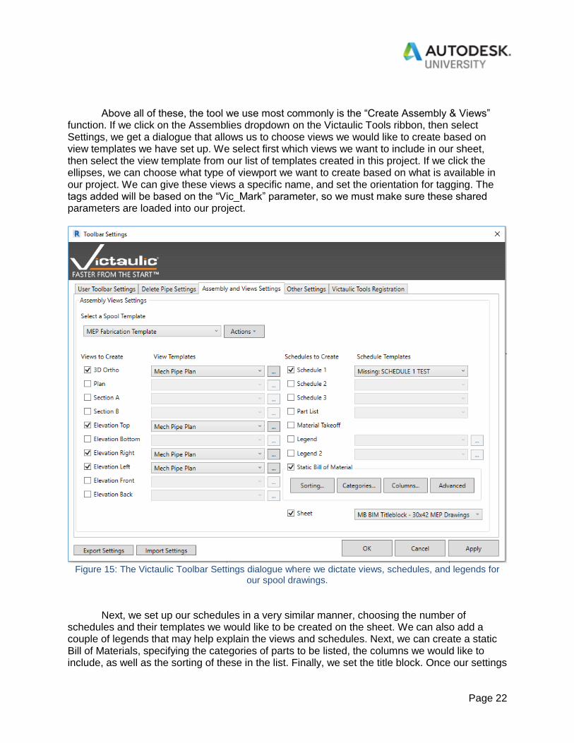
Above all of these, the tool we use most commonly is the “Create Assembly & Views” function. If we click on the Assemblies dropdown on the Victaulic Tools ribbon, then select Settings, we get a dialogue that allows us to choose views we would like to create based on view templates we have set up. We select first which views we want to include in our sheet, then select the view template from our list of templates created in this project. If we click the ellipses, we can choose what type of viewport we want to create based on what is available in our project. We can give these views a specific name, and set the orientation for tagging. The tags added will be based on the “Vic_Mark” parameter, so we must make sure these shared parameters are loaded into our project.
Figure 15: The Victaulic Toolbar Settings dialogue where we dictate views, schedules, and legends for
our spool drawings.
Next, we set up our schedules in a very similar manner, choosing the number of schedules and their templates we would like to be created on the sheet. We can also add a couple of legends that may help explain the views and schedules. Next, we can create a static Bill of Materials, specifying the categories of parts to be listed, the columns we would like to include, as well as the sorting of these in the list. Finally, we set the title block. Once our settings

Page 23
for the project are created, we can export and save these for a later date. Likewise, we can import these settings from previous projects, we simply need to ensure the templates we have chosen are common among the different projects. Now that we have the settings ready to go, we next select which pipes we want to put into any given assembly, then click the “Create Assembly & Views” button. A dialogue will pop up allowing us to give the assembly a prefix and number, choosing which template we would like to use. We hit OK and our sheet is automatically created with all of our views and schedules. We simply move these into place and we are good to go.
Figure 16: A simple example of a spool drawing created by Victaulic Pipe Tools.