Embed Size (px)
DESCRIPTION
Blast resistant Control Building
Citation preview
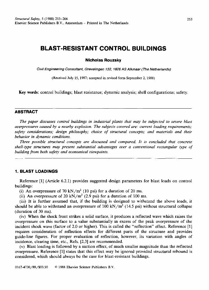
Structural Safety, 5 (1988) 253-266 253 Elsevier Science Publishers B.V., Amsterdam - Printed in The Netherlands
BLAST-RESISTANT CONTROL BUILDINGS
Nicholas Rouzsky
Civil Engineering Consultant, Grevelingen 132, 1826 AS Alkmaar (The Netherlands)
(Received July 15, 1987; accepted in revised form September 2, 1988)
Key words: control buildings; blast resistance; dynamic analysis; shell configurations; safety.
ABSTRACT
The paper discusses control buildings in industrial plants that may be subjected to severe blast overpressures caused by a nearby explosion. The subjects covered are: current loading requirements," safety considerations," design philosophy; choice of structural concepts; and materials and their behavior in dynamic conditions.
Three possible structural concepts are discussed and compared. It is concluded that concrete shell-type structures may present substantial advantages over a conventional rectangular type of building from both safety and economical viewpoints.
1. BLAST LOADINGS
Reference [1] (Article 6.2.1) provides suggested design parameters for blast loads on control buildings:
(i) An overpressure of 70 k N / m 2 (10 psi) for a duration of 20 ms. (ii) An overpressure of 20 k N / m 2 (2.9 psi) for a duration of 100 ms. (iii) It is further assumed that, if the building is designed to withstand the above loads, it
should be able to withstand an overpressure of 100 k N / m 2 (14.5 psi) without structural collapse (duration of 30 ms).
(iv) When the shock front strikes a solid surface, it produces a reflected wave which raises the overpressure on this surface to a value substantially in excess of the peak overpressure of the incident shock wave (factor of 2.0 or higher). This is called the "reflection" effect. Reference [1] requires consideration of reflection effects for different parts of the structure and provides guide-line figures. For proper evaluation of reflection, however, its variation with angles of incidence, clearing time, etc., Refs. [2,3] are recommended.
(v) Blast loading is followed by a suction effect, of much smaller magnitude than the reflected overpressure. Reference [1] states that this effect may be ignored provided structural rebound is considered, which should always be the case for blast-resistant buildings.
0167-4730/88/$03.50 © 1988 Elsevier Science Publishers B.V.
254
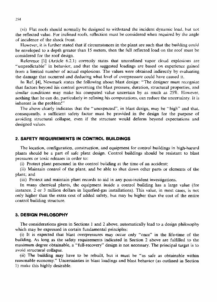
(vi) Flat roofs should normally be designed to withstand the incident dynamic load, but not the reflected value. For inclined roofs, reflection must be considered when required by the angle of incidence of the shock front.
However, it is further stated that if circumstances in the plant are such that the building could be enveloped to a depth greater than 15 meters, then the full reflected load on the roof must be considered for the roof design.
Reference [1] (Article 6.2.1) correctly states that unconfined vapor cloud explosions are "unpredictable" in behavior, and that the suggested loadings are based on experience gained from a limited number of actual explosions. The values were obtained indirectly by evaluating the damage that occurred and deducing what level of overpressure could have caused it.
In Ref. [4], Newmark states the following about blast design: "The designer must recognize that factors beyond his control governing the blast pressure, duration, structural properties, and similar conditions may make his computed value uncertain by as much as 25%. However, nothing that he can do, particularly in refining his computations, can reduce the uncertainty. It is inherent in the problem!"
The above clearly indicates that the "unexpected", in blast design, may be "high" and that, consequently, a sufficient safety factor must be provided in the design for the purpose of avoiding structural collapse, even if the structure would deform beyond expectations and designed values.
2. SAFETY REQUIREMENTS IN CONTROL BUILDINGS
The location, configuration, construction, and equipment for control buildings in high-hazard plants should be a part of safe plant design. Control buildings should be resistant to blast pressures or toxic releases in order to:
(i) Protect plant personnel in the control building at the time of an accident; (ii) Maintain control of the plant, and be able to shut down other parts or elements of the
plant; and (iii) Protect and maintain plant records to aid in any post-incident investigations. In many chemical plants, the equipment inside a control building has a large value (for
instance, 2 or 3 million dollars in liquefied-gas installations). This value, in most cases, is not only higher than the extra cost of added safety, but may be higher than the cost of the entire control building structure.
3. DESIGN PHILOSOPHY
The considerations given in Sections 1 and 2 above, automatically lead to a design philosophy which may be expressed in certain fundamental principles:
(i) It is expected that blast overpressures may occur only "once" in the life-time of the building. As long as the safety requirements indicated in Section 2 above are fulfilled to the maximum degree obtainable, a "full-recovery" design is not necessary. The principal target is to avoid structural collapse.
(ii) The building may have to be rebuilt, but it must be "as safe as obtainable within reasonable economy." Uncertainties in blast loadings and blast behavior (as outlined in Section 1) make this highly desirable.
255
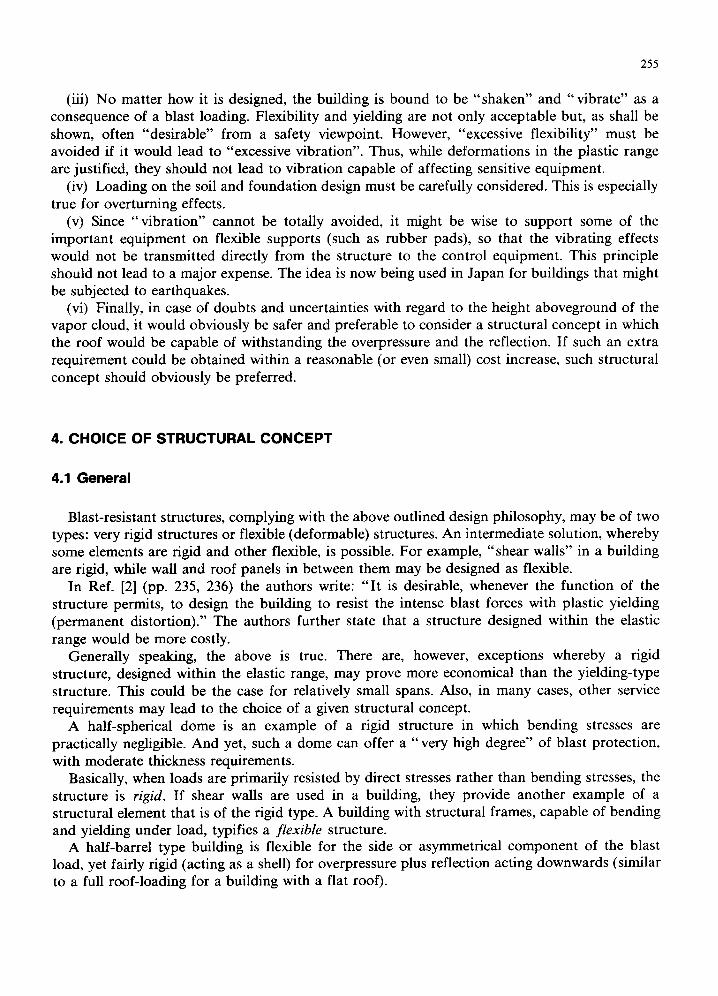
(iii) No matter how it is designed, the building is bound to be "shaken" and "vibrate" as a consequence of a blast loading. Flexibility and yielding are not only acceptable but, as shall be shown, often "desirable" from a safety viewpoint. However, "excessive flexibility" must be avoided if it would lead to "excessive vibration". Thus, while deformations in the plastic range are justified, they should not lead to vibration capable of affecting sensitive equipment.
(iv) Loading on the soil and foundation design must be carefully considered. This is especially true for overturning effects.
(v) Since "vibrat ion" cannot be totally avoided, it might be wise to support some of the important equipment on flexible supports (such as rubber pads), so that the vibrating effects would not be transmitted directly from the structure to the control equipment. This principle should not lead to a major expense. The idea is now being used in Japan for buildings that might be subjected to earthquakes.
(vi) Finally, in case of doubts and uncertainties with regard to the height aboveground of the vapor cloud, it would obviously be safer and preferable to consider a structural concept in which the roof would be capable of withstanding the overpressure and the reflection. If such an extra requirement could be obtained within a reasonable (or even small) cost increase, such structural concept should obviously be preferred.
4. CHOICE OF STRUCTURAL CONCEPT
4.1 General
Blast-resistant structures, complying with the above outlined design philosophy, may be of two types: very rigid structures or flexible (deformable) structures. An intermediate solution, whereby some elements are rigid and other flexible, is possible. For example, "shear walls" in a building are rigid, while wall and roof panels in between them may be designed as flexible.
In Ref. [2] (pp. 235, 236) the authors write: " I t is desirable, whenever the function of the structure permits, to design the building to resist the intense blast forces with plastic yielding (permanent distortion)." The authors further state that a structure designed within the elastic range would be more costly.
Generally speaking, the above is true. There are, however, exceptions whereby a rigid structure, designed within the elastic range, may prove more economical than the yielding-type structure. This could be the case for relatively small spans. Also, in many cases, other service requirements may lead to the choice of a given structural concept.
A half-spherical dome is an example of a rigid structure in which bending stresses are practically negligible. And yet, such a dome can offer a "very high degree" of blast protection, with moderate thickness requirements.
Basically, when loads are primarily resisted by direct stresses rather than bending stresses, the structure is rigid. If shear walls are used in a building, they provide another example of a structural element that is of the rigid type. A building with structural frames, capable of bending and yielding under load, typifies a flexible structure.
A half-barrel type building is flexible for the side or asymmetrical component of the blast load, yet fairly rigid (acting as a shell) for overpressure plus reflection acting downwards (similar to a full roof-loading for a building with a flat roof).
256
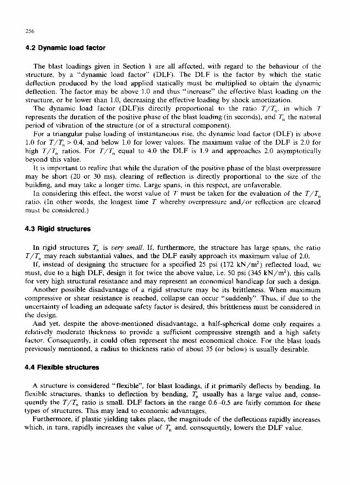
4.2 Dynamic load factor
The blast loadings given in Section 1 are all affected, with regard to the behaviour of the structure, by a "dynamic load factor" (DLF). The DLF is the factor by which the static deflection produced by the load applied statically must be multiplied to obtain the dynamic deflection. The factor may be above 1.0 and thus "increase" the effective blast loading on the structure, or be lower than 1.0, decreasing the effective loading by shock amortization.
The dynamic load factor (DLF)is directly proportional to the ratio T/Tn, in which T represents the duration of the positive phase of the blast loading (in seconds), and T n the natural period of vibration of the structure (or of a structural component).
For a triangular pulse loading of instantaneous rise, the dynamic load factor (DLF) is above 1,0 for T / T , > 0.4, and below 1.0 for lower values. The maximum value of the DLF is 2.0 for high T/T~ ratios. For T / T n equal to 4.0 the DLF is 1.9 and approaches 2.0 asymptotically beyond this value.
It is important to realize that while the duration of the positive phase of the blast overpressure may be short (20 or 30 ms), clearing of reflection is directly proportional to the size of the building, and may take a longer time. Large spans, in this respect, are unfavorable.
In considering this effect, the worst value of T must be taken for the evaluation of the T / T n ratio. (In other words, the longest time T whereby overpressure a n d / o r reflection are cleared must be considered.)
4.3 Rigid structures
In rigid structures Tn is very small. If, furthermore, the structure has large spans, the ratio T / T , may reach substantial values, and the DLF easily approach its maximum value of 2.0.
If, instead of designing the structure for a specified 25 psi (172 k N / m 2) reflected load, we must, due to a high DLF, design it for twice the above value, i.e. 50 psi (345 kN/m2) , this calls for very high structural resistance and may represent an economical handicap for such a design.
Another possible disadvantage of a rigid structure may be its brittleness. When maximum compressive or shear resistance is reached, collapse can occur "suddenly". Thus, if due to the uncertainty of loading an adequate safety factor is desired, this brittleness must be considered in the design.
And yet, despite the above-mentioned disadvantage, a half-spherical dome only requires a relatively moderate thickness to provide a sufficient compressive strength and a high safety factor. Consequently, it could often represent the most economical choice. For the blast loads previously mentioned, a radius to thickness ratio of about 35 (or below) is usually desirable.
4.4 Flexible structures
A structure is considered "flexible", for blast loadings, if it primarily deflects by bending. In flexible structures, thanks to deflection by bending, T n usually has a large value and, conse- quently the T / T n ratio is small. DLF factors in the range 0.6-0.5 are fairly common for these types of structures. This may lead to economic advantages.
Furthermore, if plastic yielding takes place, the magnitude of the deflections rapidly increases which, in turn, rapidly increases the value of T n and, consequently, lowers the DLF value.
257
In flexible structures it is often sufficient to provide resistance to only 20% or 25% of the design blast loading, since " load attenuation" by deflection takes care of the rest. The economic advantage of such a solution is often worth considering.
To achieve this, however, materials must currently be chosen so that the ratio of allowed yielding to rupture provides a sufficient safety factor. Since only the order of magnitude of plastic deformation can be evaluated by design, this requirement for materials is very important.
5. CHOICE OF CONSTRUCTION MATERIALS
In order to define a satisfactory performance of a given material versus failure, a physical measure is required. This measure, in dynamic analysis, is called the ductility ratio.
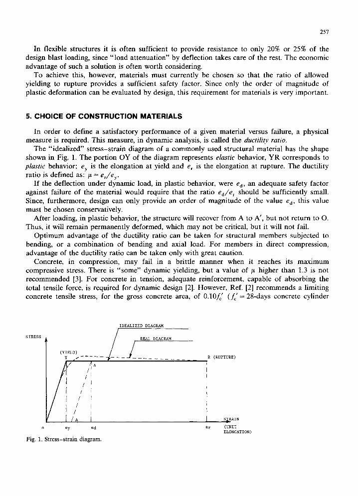
The "idealized" stress-strain diagram of a commonly used structural material has the shape shown in Fig. 1. The portion OY of the diagram represents elastic behavior, YR corresponds to plastic behavior; ey is the elongation at yield and e r is the elongation at rupture. The ductility ratio is defined as: # = e r / e y .
If the deflection under dynamic load, in plastic behavior, were Ca, an adequate safety factor against failure of the material would require that the ratio e J e r should be sufficiently small. Since, furthermore, design can only provide an order of magnitude of the value e d, this value must be chosen conservatively.
After loading, in plastic behavior, the structure will recover from A to A', but not return to O. Thus, it will remain permanently deformed, which may not be critical, but it will not fail.
Opt imum advantage of the ductility ratio can be taken for structural members subjected to bending, or a combination of bending and axial load. For members in direct compression, advantage of the ductility ratio can be taken only with great caution.
Concrete, in compression, may fail in a brittle manner when it reaches its maximum compressive stress. There is "some" dynamic yielding, but a value of/.t higher than 1.3 is not recommended [3]. For concrete in tension, adequate reinforcement, capable of absorbing the total tensile force, is required for dynamic design [2]. However, Ref. [2] recommends a limiting concrete tensile stress, for the gross concrete area, of 0.10fc' ( fc '= 28-days concrete cylinder
STRESS
(YIELD) Y i
/ , /
/
/ /
/ [ /A'
o ey ed
Fig. 1. Stress-strain diagram.
IDEALIZED DIAGRAM
/ REAL DIAGRAM
R (RUPTURE)
S[RAIN
er (UNIT ELONGATION)
258
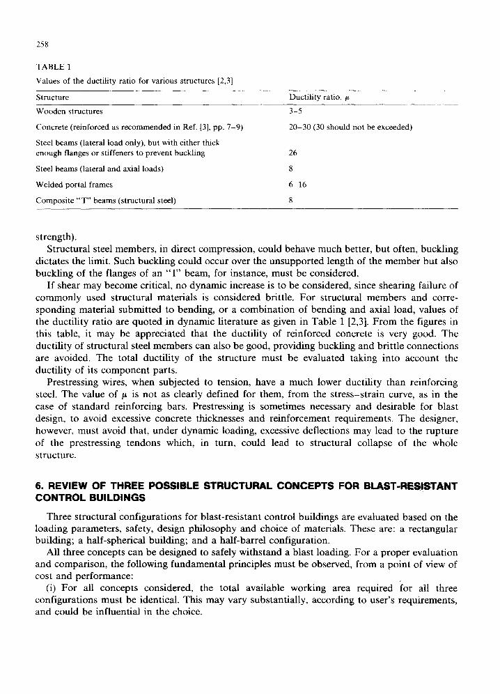
TABLE 1
Values of the ductility ratio for various structures [2,3]
Structure Ductility ratio, /t
Wooden structures
Concrete (reinforced as recommended in Ref. [3], pp. 7-9)
Steel beams (lateral load only), but with either thick enough flanges or stiffeners to prevent buckling
Steel beams (lateral and axial loads)
Welded portal frames
Composite "' T" beams (structural steel)
3-5
20-30 (30 should not be exceeded)
26
8
6-16
8
strength). Structural steel members, in direct compression, could behave much better, but often, buckling
dictates the limit. Such buckling could occur over the unsupported length of the member but also buckling of the flanges of an "I" beam, for instance, must be considered.
If shear may become critical, no dynamic increase is to be considered, since shearing failure of commonly used structural materials is considered brittle. For structural members and corre- sponding material submitted to bending, or a combination of bending and axial load, values of the ductility ratio are quoted in dynamic literature as given in Table I [2,3]. From the figures in this table, it may be appreciated that the ductility of reinforced concrete is very good. The ductility of structural steel members can also be good, providing buckling and brittle connections are avoided. The total ductility of the structure must be evaluated taking into account the ductility of its component parts.
Prestressing wires, when subjected to tension, have a much lower ductility than reinforcing steel. The value of/~ is not as clearly defined for them, from the stress-strain curve, as in the case of standard reinforcing bars. Prestressing is sometimes necessary and desirable for blast design, to avoid excessive concrete thicknesses and reinforcement requirements. The designer, however, must avoid that, under dynamic loading, excessive deflections may lead to the rupture of the prestressing tendons which, in turn, could lead to structural collapse of the whole structure.
6. REVIEW OF THREE POSSIBLE STRUCTURAL CONCEPTS FOR B L A S T - R E ~ T A N T CONTROL BUILDINGS
Three structural configurations for blast-resistant control buildings are evaluated based on the loading parameters, safety, design philosophy and choice of materials. These are: a rectangular building; a half-spherical building; and a half-barrel configuration.
All three concepts can be designed to safely withstand a blast loading. For a proper evaluation and comparison, the following fundamental principles must be observed, from a point of view of cost and performance:
(i) For all concepts considered, the total available working area required for all three configurations must be identical. This may vary substantially, according to user's requirements, and could be influential in the choice.
259
(ii) Designs must be compared on the basis of fairly similar reliability levels. This may require upgrading some aspects of every solution.
(iii) Modifications may be required, in all 3 concepts, to provide for the full downwards impact of overpressure plus reflection (roof-type loading). If such added safety can be obtained at a reasonable or minor cost increase, it represents a very attractive addition to the solution chosen.
In the evaluation which follows, we shall consider the following items: • Design items, for each concept, which must receive careful attention and which may
influence the safety and cost of the concept. • Brief considerations regarding design procedures and dimensioning of the structure. • Considerations regarding the economy of the structure chosen.
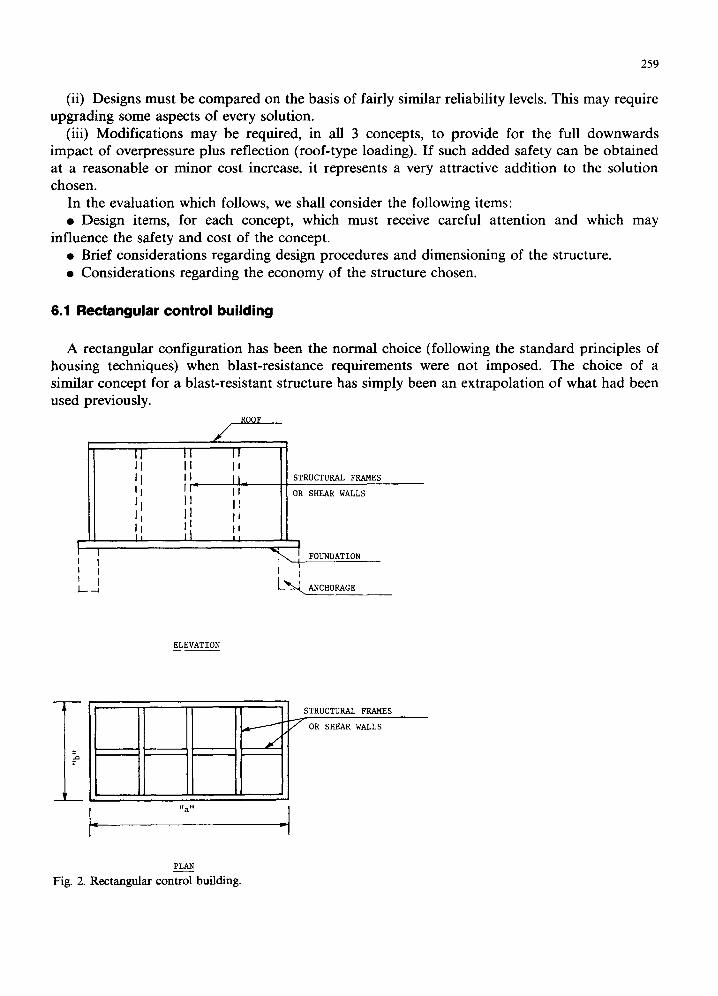
6.1 Rectangular control building
A rectangular configuration has been the normal choice (following the standard principles of housing techniques) when blast-resistance requirements were not imposed. The choice of a similar concept for a blast-resistant structure has simply been an extrapolation of what had been used previously.
ROOF
/ I I 11 i l i , I I l i _ I I= l l - i l I I ]I fj l[ il 1 | 1
1 i I I i i
L - ¢
I STRUCTURAL FRAMES OR SHEAR WALLS
FOUNDATION
I I [ - - ~ ANCHORAGE
ELEVATION
D
,dr..-. - ~ j
J
STRUCTURAL FRAMES
7 OR SHEAR WALLS
PLAN Fig. 2. Rectangular control building.
260
Two stories, especially with space limitations, are often more economical than one story for buildings following standard housing procedures. However, for blast resistance, a higher building substantially increases the overturning effect and loadings on the foundation. Thus, a one-story building is normally preferable for blast-resistance!
The ratio of length to width of the building ( a / b on Fig. 2) can be chosen according to the available space. However, the width b should not be chosen too small for a blast-resistant building, because of the overturning effect and consequent rise of pressure on the soil.
Due to the one-sided initial impact of the blast overpressure, the building has a tendency to displace horizontally. Frictional resistance of the soil may be insufficient to prevent such a movement. To mobilize passive resistance of the soil and avoid excessive "shaking", the foundation could be "anchored" (as shown by the dotted lines on Fig. 2). If piles are required, they could also provide the "anchoring" effect.
The main carrying elements may be "shear walls" or structural frames. In Ref. [2] (p. 295) the authors state: "For surface structures, the shear-wall system should be used whenever possible, since this type is superior to the conventional rigid-frame system in regards to strength and cost. The shear walls, floors and roofs should preferably be of reinforced concrete."
Biggs [5] (page 297) confirms the above, although he recognizes the fact that shear walls have a low ductility and, thus, a high DLF. Their strength, however, prevails over these disadvantages of "rigid" elements.
The disadvantage of shear walls, however, is that they compartmentalize and obstruct the space within the building, which most users do not desire. For this reason, structural frames are usually preferred.
A typical structural frame is shown on Fig. 3. Such structural frames, as stated in Ref. [1], can be of the "flexible" type, which means that large plastic deflections, under blast loading, can be allowed, providing safety against collapse is assured.
Careful consideration in the design of structural frames should be given to the connections (A, A', A" and B, B', B"). For the bot tom connections (A, A', A") it should be recognized that the soil may give way under the side impact of the blast load, initiating rotation (as shown by the dotted line in Fig. 3). This is somewhat similar to a "plastic hinge" effect, and must be considered carefully in design.
When all connections, but especially B, B' and B", start yielding and going into the plastic range, the bending moments in all members of the frame rapidly increase. To avoid "folding" and consequent collapse of the frame, the plastic bending resistance of all connections must be very carefully studied. Also, the fact that bending moments change sign as the shock front traverses the building may have a major influence on the design and must be considered.
B B I B ~'
j % i %
Fig. 3. S t r u c t u r a l f r a m e .
261
The major problem of all connections such as A, A', A", B, B', B" is that they represent locations of high bending moments and, consequently, high stress concentrations. This limits the behavior of structural frames in the plastic range.
If full blast overpressure, plus reflection, on a flat roof is to be considered, the cost of the structure increases substantially. Not only is the load on the foundation greatly increased (requiring a stronger foundation), but also the structural frames and the roof panels require a much stronger design.
It is, of course, possible to provide bracing (as shown by the dotted lines at B, B' and B" on Fig. 3) to improve the strength and resistance of the structural frames. Such a technique has in fact been used. However, the frame then becomes much more rigid, which, in turn, requires consideration of a higher DLF and which, also, lowers the overall ductility of the frame.
6.2 Shell-type control building
Shell structures, with double or single curvature, have often been recommended and used for blast-resistant designs in civil as well as military installations. This fact is not surprising, considering some of the advantages they offer:
(i) Shells can be of a totally "rigid" type, which is the case of a spherical configuration (half-sphere). They can also be of a "semi-rigid" type, such as a half-barrel: for a blast load acting downwards (roof load) the half-barrel is practically rigid. For the side component of the blast load, it is "flexible" and capable of large plastic deflections.
(ii) Despite the above, the effect of curvature provides major benefits: it reduces the values of the bending moments, it helps eliminating areas of high stress-concentration and, finally, for proper chosen radius-to-thickness ratios (as mentioned in Section 4.3 above) it provides a very high safety factor against brittle failure in direct compression. These advantages often offset, by far, the higher DLF to be considered in design.
(iii) The half-barrel and the half-sphere have the configuration shown on Fig. 4. For both cases, the connections at A and A' can be designed as plastic hinges. In fact, it is highly desirable to design them as plastic hinges, for three main reasons: it avoids introducing bending moments into the foundation slab; for the half-barrel, it allows more plasticity and more deformation; and it does not affect the stability of the structure. (Note: In a rigid frame concept, such bottom connections as A and A', to the contrary, must preferably possess a substantial bending
f I J
/_4
SHELL
J, f i I I i
I . . - _ 4
F O U N D A T I O N
Fig. 4. Shell-type control building.
A N C H O R A G E
262
V/2 ~ V
~ HbIT
l- Fig. 5. Loads on a half-shel l .
v/2
-i
resistance capacity since, otherwise, too much demand can be made of the upper connections B, B', B" (Fig. 3).)
These connections at A and A', in the half-barrel or half-sphere, must only be able to take shear, which is easily accomplished.
Stresses, in both of the above types, are distributed "throughout the structures" in a smooth and continuous fashion. There are no stress-concentrations as is the case in structural frames. For plastic behavior, this is a major advantage.
(iv) The half-shell (180 ° opening angle) is very important in these structures for blast resistance, since it avoids the overturning problem. No other configuration, for blast, can offer this advantage.
The above can very easily be explained: It is known from test data [3] that blast overpressure and reflection act "radially" on the surface they encounter, with lateral components of the load (such as friction on the surface, for instance) being of negligible character. Looking at Fig. 5, as the blast loading progresses in time, no matter what its position is, each load component acts towards the center of the structure, where it decomposes into two components H and V. Due to symmetry, the component V decomposes, at the supports, into two equal components, V/2, acting downwards.
Thus, for the half-barrel, it is not essential, as was the case for the rectangular configuration, to impose a structural minimum to the width b. In some cases, when space is limited, this is an advantage.
The component H must be absorbed horizontally. Similarly to the rectangular building, friction on the soil would normally be insufficient. Thus, to avoid excessive displacement and shaking, the foundation must be anchored, as shown by the dotted lines on Fig. 4. Piles could also be used.
(v) Reference [1] states that the possibility of reflection on a flat roof is low. However, it also mentions that if a control building (considering emission possibilities) may be enveloped by a vapor cloud to a depth greater than 15 m, then full reflected load on the roof must be considered in design.
Such high roof loading, for a shell-type structure, only majorly affects the foundation of the structure. On the other hand, for a rectangular building, such a roof loading requires a substantial increase in strength of not only the foundation, but also of the carrying structural
263
frames and of the roof panels. The cost increase, consequently, for a reflected roof load, is substantially higher for a rectangular building than for a shell structure.
(vi) In a configuration different from the one described in (iv) above, reactions at the supports are not necessarily equal, which in turn, may lead to an undesirable overloading on the soil. In a rectangular building, in particular, even the possibility of lifting at one end must seriously be considered in design.
6.3 Half-spherical control building
Whether a blast loading acts sideways or downwards (plus reflection), the half-sphere remains rigid, since all bending in it is of totally negligible character. Despite this fact, it is a very strong structure for blast resistance.
The only disadvantage of the half-sphere, for normal sizes of control buildings, comes from a "lot of wasted space" in its upper part. However, this disadvantage can be eliminated by providing a second floor! A "suspended ceiling" concept, for instance, can represent an easy and economical solution (Fig. 6).
The suspension system (anchorages "A") should be of flexible type, to avoid transmitting some of the inevitable "shaking" to the ceiling and equipment located on it. Such an anchoring system presents no difficulty.
For a specified total working area, the use of a second floor reduces the area required at soil level. This leads to a smaller radius of curvature and, maintaining the same safe radius-to-thick- ness ratio, also to a reduction of the shell thickness. This may not only be economical for the structure, but also saves space in the plant, which sometimes is advantageous.
6.4 Half-barrel control building
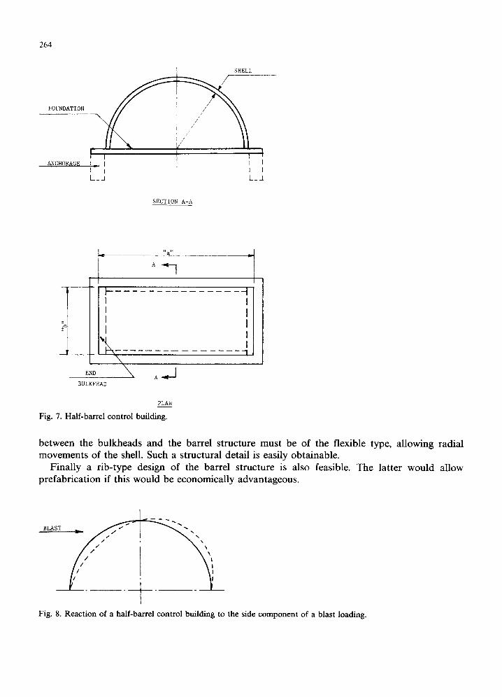
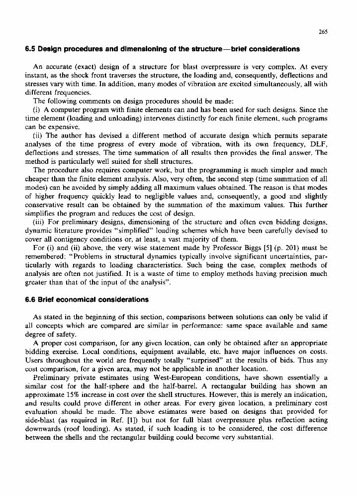
If a rectangular (in plan) configuration is preferred, the half-barrel represents an attractive choice (Fig. 7). For a load acting downwards it is "practically" rigid and acts similarly to the half-sphere. For the side component of the blast loading, it deflects as shown on Fig. 8.
Bending moments and stresses, in this condition, are smoothly and well distributed, without sharp corners and stress concentrations. This accounts for an excellent plastic behavior with a very high safety factor.
At both ends of the half-barrel closure bulkheads must be provided. To avoid a "stiffening effect" and allow the "advantageous deflection" of the barrel shown on Fig. 8, the connection
viA-
l \
~ SUSPENSDED CEILING
Fig. 6. Suspended ceiling in a hal~sphere.
264
FOUNDATION
ANCHORAGE
[ , , I t--I I l 1" I I I L_A L_A
SECTION A-A
L_
F
END
BULKHEAD
"a"
A ~
A~
PLAN
Fig. 7. Half-barrel control building.
-j I I I I I 1
between the bulkheads and the barrel structure must be of the flexible type, allowing radial movements of the shell. Such a structural detail is easily obtainable.
Finally a rib-type design of the barrel structure is also feasible. The latter would allow prefabrication if this would be economically advantageous.
BLAST J !
Fig. 8. Reaction of a half-barrel control building to the side component of a blast loading.
265
6.5 Design procedures and dimensioning of the structure mbrief considerations
An accurate (exact) design of a structure for blast overpressure is very complex. At every instant, as the shock front traverses the structure, the loading and, consequently, deflections and stresses vary with time. In addition, many modes of vibration are excited simultaneously, all with different frequencies.
The following comments on design procedures should be made: (i) A computer program with finite elements can and has been used for such designs. Since the
time element (loading and unloading) intervenes distinctly for each finite element, such programs can be expensive.
(ii) The author has devised a different method of accurate design which permits separate analyses of the time progress of every mode of vibration, with its own frequency, DLF, deflections and stresses. The time summation of all results then provides the final answer. The method is particularly well suited for shell structures.
The procedure also requires computer work, but the programming is much simpler and much cheaper than the finite element analysis. Also, very often, the second step (time summation of all modes) can be avoided by simply adding all maximum values obtained. The reason is that modes of higher frequency quickly lead to negligible values and, consequently, a good and slightly conservative result can be obtained by the summation of the maximum values. This further simplifies the program and reduces the cost of design.
(iii) For preliminary designs, dimensioning of the structure and often even bidding designs, dynamic literature provides "simplified" loading schemes which have been carefully devised to cover all contigency conditions or, at least, a vast majority of them.
For (i) and (ii) above, the very wise statement made by Professor Biggs [5] (p. 201) must be remembered: "Problems in structural dynamics typically involve significant uncertainties, par- ticularly with regards to loading characteristics. Such being the case, complex methods of analysis are often not justified. It is a waste of time to employ methods having precision much greater than that of the input of the analysis".
6.6 Brief economical considerations
As stated in the beginning of this section, comparisons between solutions can only be valid if all concepts which are compared are similar in performance: same space available and same degree of safety.
A proper cost comparison, for any given location, can only be obtained after an appropriate bidding exercise. Local conditions, equipment available, etc. have major influences on costs. Users throughout the world are frequently totally "surprised" at the results of bids. Thus any cost comparison, for a given area, may not be applicable in another location.
Preliminary private estimates using West-European conditions, have shown essentially a similar cost for the half-sphere and the half-barrel. A rectangular building has shown an approximate 15% increase in cost over the shell structures. However, this is merely an indication, and results could prove different in other areas. For every given location, a preliminary cost evaluation should be made. The above estimates were based on designs that provided for side-blast (as required in Ref. [1]) but not for full blast overpressure plus reflection acting downwards (roof loading). As stated, if such loading is to be considered, the cost difference between the shells and the rectangular building could become very substantial.
266
Finally, one essential consideration for control buildings (already mentioned in Section 2) comes from the fact that the cost of these buildings may often be smaller than the cost of the expensive equipment located in them. This further favors the safest possible solution--capable of withstanding the "unforeseen" condition, even if the latter has not necessarily been required by the design specifications.
7. CONCLUSIONS AND RECOMMENDATIONS
This paper has briefly outlined the fact that structures capable of withstanding strong blast overpressures are guided by principles which are often totally different from those involved with statically applied loads. Sometimes, control buildings had been designed for "equivalent static loads". While space limitations prevent a detailed comparison between dynamic or static designs, it can be stated that the "equivalent static load" approach may easily lead to designs which are neither safe in plastic behaviour nor economical.
The paper also shows that shell-type concrete structures present major advantages of safety and, usually economy, over the conventional rectangular configuration. Since safety and blast-re- sistance of the control building, and protection of the personnel and equipment inside it, are of major importance in the overall safety of the entire plant, it is recommended that shell type solutions be considered for future industrial installations.
ACKNOWLEDGEMENT
The author wants to express his thanks to Mr. J.J. Closner, former President of Preload Technology, Inc., his friend and co-worker for many years, who asked him to perform this study and encouraged him to write this paper.
REFERENCES
1 Process Plant Hazard and Control Building Design, Chemical Industry Safety and Health Council, Chemical Industries Associated Limited, United Kingdom, 1980.
2 C.H. Norris, R.J. Hansen, M.J. Holley, J.M. Biggs, S. Namyet and J.K. Minami, Structural Design for Dynamic Loads, McGraw Hill, New York, NY, 1959.
3 N.M. Newmark and J.D. Haltiwanger, Air Force Design Manual: Principles and Practices for Design of Hardened Structures, Technical Documentary Report No. AFSWC-TDR-62-138, December 1962.
4 N.M. Newmark, An engineering approach to blast resistant design, University of Illinois Bulletin, Paper No. 2786, June 1956.
5 J.M. Biggs, Introduction to Structural Dynamics, McGraw Hill, New York, NY, 1969.