Embed Size (px)
Citation preview

I:\CIRC\MSC\01\1330.doc
INTERNATIONAL MARITIME ORGANIZATION 4 ALBERT EMBANKMENT LONDON SE1 7SR Telephone: 020 7735 7611 Fax: 020 7587 3210
IMO
E
Ref. T4/3.01 MSC.1/Circ.1330 11 June 2009
GUIDELINES FOR MAINTENANCE AND REPAIR OF PROTECTIVE COATINGS 1 The Committee, at its eighty-sixth session (27 May to 5 June 2009), having recognized the need for Guidelines for maintenance and repair of protective coatings, taking into account the amendments to SOLAS regulations II-1/3-2 and XII/6 and the Performance standard for protective coatings for dedicated seawater ballast tanks in all types of ships and double-side skin spaces of bulk carriers, adopted by resolutions MSC.216(82) and MSC.215(82), respectively, considered the proposal by the Sub-Committee on Ship Design and Equipment, at its fifty-second session, and approved Guidelines for maintenance and repair of protective coatings, set out in the annex. 2 Member Governments are invited to apply the annexed Guidelines during survey, assessment and repair of protective coatings in ballast tanks on or after 1 January 2011 and bring them to the attention of shipowners, shipbuilders and other parties concerned.
***


MSC.1/Circ.1330
I:\CIRC\MSC\01\1330.doc
ANNEX
GUIDELINES FOR MAINTENANCE AND REPAIR OF PROTECTIVE COATINGS CONTENTS 1 GENERAL 2 APPLICATION AND DEFINITIONS 3 SURVEY RECOMMENDATIONS 4 COATING CONDITIONS 4.1 �GOOD�, �FAIR�, �POOR� 4.2 Areas under consideration 4.3 In-service condition monitoring 5 COATING MAINTENANCE 5.1 Process considerations for maintenance 5.2 Principles for maintenance 5.3 Recommended maintenance 6 COATING REPAIRS 6.1 Process considerations for repairs 6.2 Principles for repairs 6.3 Recommended repair 7 COATING TECHNICAL FILE (CTF) 8 REFERENCES
MSC.1/Circ.1330 ANNEX Page 2
I:\CIRC\MSC\01\1330.doc
1 GENERAL 1.1 The purpose of these Guidelines is to assist surveyors, shipowners, shipyards, flag Administrations and other interested parties involved in the survey, assessment and repair of protective coatings in ballast tanks. 1.2 The ability of the coating system to reach its target useful life depends on the type of coating system, steel preparation, the design of the structures, application and coating inspection and maintenance. All these aspects contribute to the good performance of the coating system. These Guidelines focus on maintenance and repair procedures for coatings. 1.3 Maintenance and repair of the protective coating system should be included in the ship�s overall maintenance and repair scheme. The effectiveness of the protective coating system, which may include the use of anodes, should be verified during the life of a ship by the Administration or an organization recognized by the Administration. 2 APPLICATION AND DEFINITIONS 2.1 These Guidelines apply to ships as specified in SOLAS regulation II-1/3-2.1.1 and focus on maintenance and repair procedures for coatings in dedicated seawater ballast tanks of all types of ships and double-side skin spaces of bulk carriers, hereinafter referred to as �ballast tanks�. They only cover in-service maintenance and repair of coatings. Corrosion prevention systems other than coating are not covered. 2.2 For the purpose of these Guidelines, the following definitions apply:
.1 Maintenance means minor coating restoration work regularly performed by a ship�s crew using normal shipboard means and tools to maintain �GOOD� or �FAIR� coating conditions. Maintenance delays or slows down the coating deterioration and effects short term steel protection.
.2 Repair means coating restoration work of a longer term nature, usually performed
during ship�s dry-docking or scheduled repair period (ship idle) to restore the �FAIR� or �POOR� coating condition to �GOOD� condition. This will usually require specialized manpower and equipment such as sand blasting equipment, operators and dehumidifiers.
2.3 These Guidelines have been developed using the best information currently available and taking into consideration that maintenance may take place when the ship is at sea, while repair usually takes place in dry-dock or during scheduled repair periods (afloat at yard). 3 SURVEY RECOMMENDATIONS 3.1 The coating system in ballast tanks should be examined in connection with:
.1 intermediate surveys for all steel ships above 500 gross tonnage exceeding five years of age; and
.2 renewal surveys for all steel ships above 500 gross tonnage.

MSC.1/Circ.1330 ANNEX
Page 3
I:\CIRC\MSC\01\1330.doc
3.2 The condition of the coating in ballast tanks should be assigned and categorized as GOOD, FAIR or POOR based on visual inspection and estimated percentage of areas with coating failure and rusty surfaces (see table 1) and recorded*. 4 COATING CONDITIONS 4.1 �GOOD�, �FAIR�, �POOR� 4.1.1 The condition of the coating in ballast tanks is assigned and categorized as �GOOD�, �FAIR� or �POOR�, based on visual inspection and estimated percentage of areas with coating failure and rusty surfaces. 4.1.2 The definitions of coating conditions �GOOD�, �FAIR� and �POOR� in the Guidelines on the enhanced programme of inspections during surveys of bulk carriers and oil tankers (resolution A.744(18)) are as follows: GOOD: Condition with only minor spot rusting.
FAIR: Condition with local breakdown of coating at edges of stiffeners and weld connections and/or light rusting over 20% or more of areas under consideration, but less than as defined for POOR condition.
POOR: Condition with general breakdown of coating over 20% or more of areas or
hard scale at 10% or more of areas under consideration. 4.1.3 These Guidelines clarify the above definitions in order to achieve unified assessment of coating conditions as follows, see also table 1 below:
GOOD: Condition with spot rusting on less than 3% of the area under consideration without visible failure of the coating. Rusting at edges or welds, should be on less than 20% of edges or weld lines in the area under consideration.
FAIR: Condition with breakdown of coating or rust penetration on less than 20% of
the area under consideration. Hard rust scale should be less than 10% of the area under consideration. Rusting at edges or welds should be on less than 50% of edges or weld lines in the area under consideration.
POOR: Condition with breakdown of coating or rust penetration on more than 20%
or hard rust scale on more than 10% of the area under consideration or local breakdown concentrated at edges or welds on more than 50% of edges or weld lines in the area under consideration.
* Refer to appendix 10 to IACS Recommendation 87 − Guidelines for Coating Maintenance and Repairs for Ballast
Tanks and Combined Cargo/Ballast Tanks on Oil Tankers, revision 1, 2006.

MSC.1/Circ.1330 ANNEX Page 4
I:\CIRC\MSC\01\1330.doc
Table 1 � �GOOD�, �FAIR� and �POOR� coating conditions
GOOD (3) FAIR POOR Breakdown of coating or area rusted (1) < 3% 3 � 20% > 20% Area of hard rust scale (1) - < 10% ≥ 10% Local breakdown of coating or rust on edges or weld lines (2) < 20% 20 � 50% > 50%
Notes: 1 % is the percentage calculated on basis of the area under consideration or of the
�critical structural area� 2 % is the percentage calculated on basis of edges or weld lines in the area under
consideration or of the �critical structural area� 3 spot rusting, i.e. rusting in spot without visible failure of coating
4.1.4 The above clarifications are further exemplified in IACS Recommendation 87 via photographs along with narrative descriptions of the condition and uniform and localized assessment scales*. 4.2 Areas under consideration 4.2.1 General 4.2.1.1 Recognizing that different areas in the tank experience different coating breakdown and corrosion patterns, the intent of this section is to subdivide the planar boundaries of the tank for evaluation of coating into areas small enough to be readily examined and evaluated by the surveyor. However, the areas subdivided should not be so small as to be structurally insignificant or too numerous to practically report on. Coating condition in each area should be reported using current practice and terminology (frame numbers, longitudinal numbers and/or strakes numbers, etc.). Each area is then rated �GOOD�, �FAIR� or �POOR� and the tank rating should not be higher than the rating of its �area under consideration� having the lowest rating**. 4.2.1.2 Special attention should be given to coating in critical structural areas which are defined*** as �locations which have been identified from calculations to require monitoring as indicated in the Coating Technical File (CTF) from new building stage or from the service history of the subject ship or from similar or sister ships (if available) to be sensitive to cracking, buckling or corrosion which would impair the structural integrity of the ship�. Each critical structural area is rated �GOOD�, �FAIR� or �POOR�, applying table 1 and the rating of each �area under consideration� should then not be higher than the rating of its critical structural area (if present) having the lowest rating.
* Refer to appendices 8 and 9 of IACS Recommendation 87 − Guidelines for Coating Maintenance and Repairs for
Ballast Tanks and Combined Cargo/Ballast Tanks on Oil Tankers, revision 1, 2006. ** Examples of how to report coating conditions with respect to areas under consideration are given in appendix 10
of IACS Recommendation 87. *** Refer to appendix 5 of IACS Recommendation 87.
MSC.1/Circ.1330 ANNEX
Page 5
I:\CIRC\MSC\01\1330.doc
4.2.1.3 The �area under consideration� with the worst coating condition should determine the frequency of surveys, such as those addressed in resolution A.744(18) for tankers. Hence, it is not intended to �average� the coating condition for all �areas under consideration� within a tank,to determine an �average� coating condition for the entire tank. 4.2.2 Ballast tanks in oil tankers Definitions of �areas under consideration� for ballast tanks in oil tankers are as follows (also illustrated for a wing ballast tank, a fore peak ballast and aft peak tank in figures 1, 2 and 3 below, respectively). Single-hull tanker − wing ballast tanks Deck and bottom Areas of deck and bottom plating with attached structure (one area to consider for deck and one area to consider for bottom). Side shell and longitudinal bulkheads Areas of side shell and longitudinal bulkheads with attached structure, in lower, middle and upper third (three areas to consider for side shell and three areas to consider for longitudinal bulkhead). Transverse bulkheads (forward and aft) Areas of transverse bulkhead and attached stiffeners, in lower, middle and upper third (three areas to consider for forward transverse bulkhead and three areas to consider for aft transverse bulkhead). Double-hull tanker Double bottom ballast tank Areas of tank boundaries and attached structure, in lower and upper half of tank (two areas to consider). Double-hull side tank Deck and bottom Areas of deck and bottom plating with attached structure (one area to consider for deck and one area to consider for bottom). Side shell and longitudinal bulkheads Areas of side shell and longitudinal bulkheads with attached structure, in lower, middle and upper third (three areas to consider for side shell and three areas to consider for longitudinal bulkhead).
MSC.1/Circ.1330 ANNEX Page 6
I:\CIRC\MSC\01\1330.doc
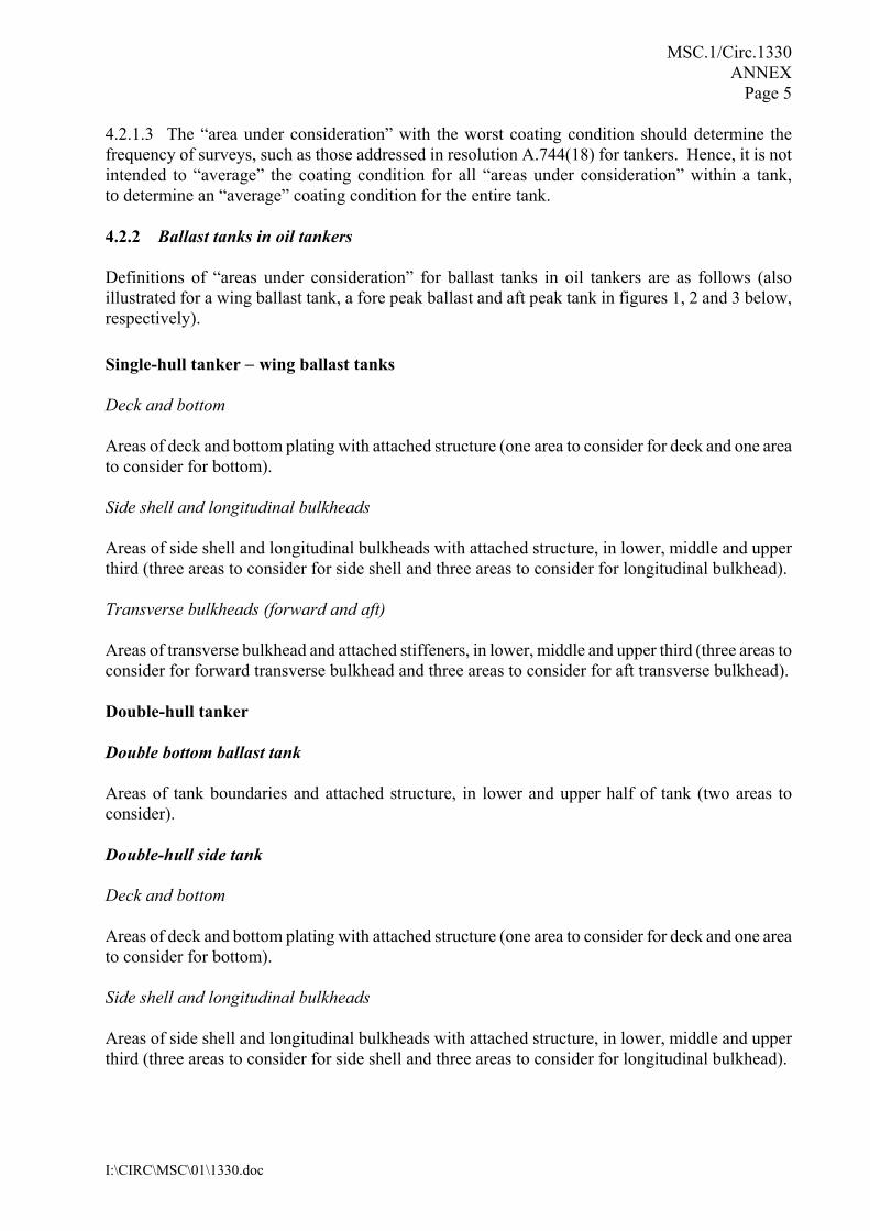
Transverse bulkheads (forward and aft) Areas of transverse bulkhead and attached stiffeners, in lower, middle and upper third (three areas to consider for forward transverse bulkhead and three areas to consider for aft transverse bulkhead).
Aft
Middle
Forward
Upper
Middle
Lower
Figure 1 � �Areas under consideration� indicated for a wing ballast tank, from one side,
i.e. deck, side shell, longitudinal bulkhead and transverse bulkheads
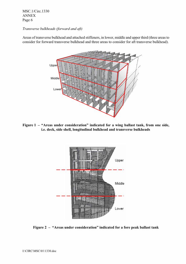
Figure 2 � �Areas under consideration� indicated for a fore peak ballast tank

MSC.1/Circ.1330 ANNEX
Page 7
I:\CIRC\MSC\01\1330.doc
Fore peak tanks Areas of tank boundaries and attached structure, in upper, middle and lower third of tank (three areas to consider). After peak tanks Areas of tank boundaries and attached structure, in lower and upper half of tank (two areas to consider).
Figure 3 � �Areas under consideration� indicated for an aft peak tank 4.2.3 Ballast tanks in ships other than oil tankers Definitions of �areas under consideration� for ballast tanks and double-side skin spaces in ships other than oil tankers, which are based on representative tank configuration, are as follows (also illustrated for topside tanks, hopper tanks, double bottom tanks, side tanks, fore peak tanks and after peak tanks in figures 4 to 9 below, respectively): Topside tanks Deck, vertical strake and bottom Areas of deck, vertical strake and bottom plating with attached structure (one area to consider for deck and vertical strake with attached structure and one area to consider for bottom).
MSC.1/Circ.1330 ANNEX Page 8
I:\CIRC\MSC\01\1330.doc
Side shell Side shell with attached structure, in lower and upper or in lower, middle and upper depending on the vertical height (two areas to consider for side shell, but if the vertical height is more than 15 m, three areas to consider). Transverse bulkheads (forward and aft) Areas of transverse bulkhead and attached stiffeners, in lower and upper or in lower, middle and upper depending on the vertical height (two areas to consider for forward transverse bulkhead and aft transverse bulkhead, but if the vertical height is more than 15 m, three areas to consider).
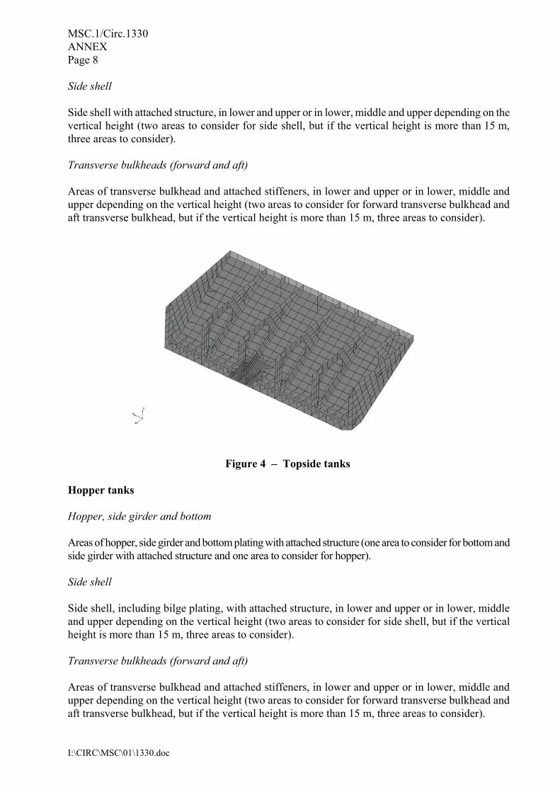
Figure 4 � Topside tanks
Hopper tanks Hopper, side girder and bottom Areas of hopper, side girder and bottom plating with attached structure (one area to consider for bottom and side girder with attached structure and one area to consider for hopper). Side shell Side shell, including bilge plating, with attached structure, in lower and upper or in lower, middle and upper depending on the vertical height (two areas to consider for side shell, but if the vertical height is more than 15 m, three areas to consider). Transverse bulkheads (forward and aft) Areas of transverse bulkhead and attached stiffeners, in lower and upper or in lower, middle and upper depending on the vertical height (two areas to consider for forward transverse bulkhead and aft transverse bulkhead, but if the vertical height is more than 15 m, three areas to consider).
MSC.1/Circ.1330 ANNEX
Page 9
I:\CIRC\MSC\01\1330.doc
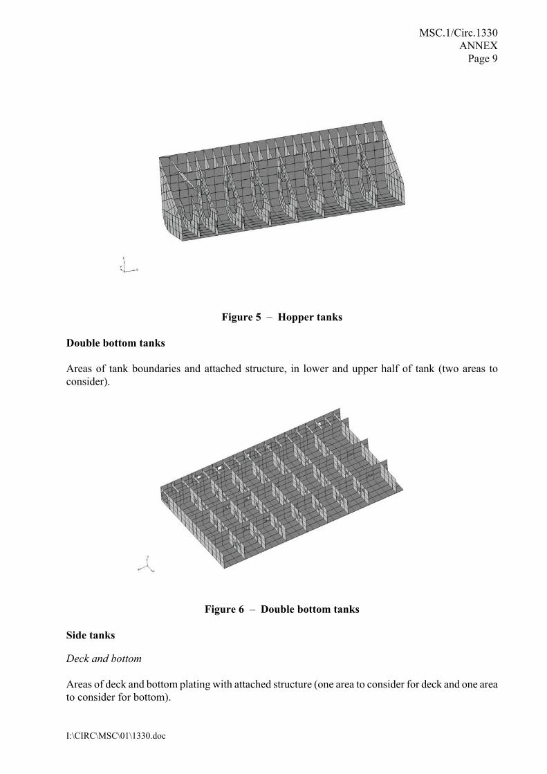
Figure 5 � Hopper tanks
Double bottom tanks Areas of tank boundaries and attached structure, in lower and upper half of tank (two areas to consider).
Figure 6 � Double bottom tanks
Side tanks Deck and bottom Areas of deck and bottom plating with attached structure (one area to consider for deck and one area to consider for bottom).

MSC.1/Circ.1330 ANNEX Page 10
I:\CIRC\MSC\01\1330.doc
Side shell and longitudinal bulkheads Side shell and longitudinal bulkheads with attached structure, in lower and upper or in lower, middle and upper depending on the vertical height (two areas to consider for side shell, but if the vertical height is more than 15 m, three areas to consider). Transverse bulkheads (forward and aft) Areas of transverse bulkhead and attached stiffeners, in lower and upper or in lower, middle and upper depending on the vertical height (two areas to consider for forward transverse bulkhead and aft transverse bulkhead, but if the vertical height is more than 15 m, three areas to consider).
Figure 7 � Side tanks Fore peak tanks Areas of tank boundaries and attached structure in upper and lower or upper, middle and lower depending on the vertical height (two areas to consider for fore peak tanks, but if the vertical height is more than 15 m, three areas to consider).
Figure 8 � Fore peak tanks
MSC.1/Circ.1330 ANNEX Page 11
I:\CIRC\MSC\01\1330.doc
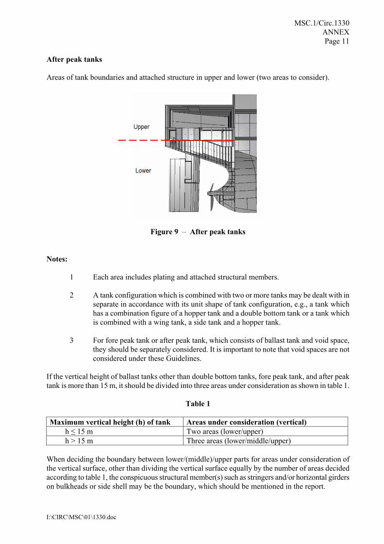
After peak tanks Areas of tank boundaries and attached structure in upper and lower (two areas to consider).
Figure 9 � After peak tanks Notes:
1 Each area includes plating and attached structural members. 2 A tank configuration which is combined with two or more tanks may be dealt with in
separate in accordance with its unit shape of tank configuration, e.g., a tank which has a combination figure of a hopper tank and a double bottom tank or a tank which is combined with a wing tank, a side tank and a hopper tank.
3 For fore peak tank or after peak tank, which consists of ballast tank and void space,
they should be separately considered. It is important to note that void spaces are not considered under these Guidelines.
If the vertical height of ballast tanks other than double bottom tanks, fore peak tank, and after peak tank is more than 15 m, it should be divided into three areas under consideration as shown in table 1.
Table 1
When deciding the boundary between lower/(middle)/upper parts for areas under consideration of the vertical surface, other than dividing the vertical surface equally by the number of areas decided according to table 1, the conspicuous structural member(s) such as stringers and/or horizontal girders on bulkheads or side shell may be the boundary, which should be mentioned in the report.
Maximum vertical height (h) of tank Areas under consideration (vertical) h ≤ 15 m Two areas (lower/upper) h > 15 m Three areas (lower/middle/upper)
MSC.1/Circ.1330 ANNEX Page 12
I:\CIRC\MSC\01\1330.doc
4.3 In-service condition monitoring 4.3.1 It is recommended that all ballast tanks, especially for ships over six years of age, are inspected at least annually by the crew. 4.3.2 Standardized reports should be used with the following information, where applicable:
.1 ship�s name; .2 tank number; .3 inspection date; .4 inspection by whom; .5 year coated; .6 coating name/type; .7 last repaired; .8 surface area; .9 coating condition (GOOD, FAIR or POOR); .10 Pitting corrosion � Yes/No; .11 amount of rust scale (in m2 or % of areas under consideration); .12 access arrangement condition; .13 sounding pipe condition; .14 vent pipe condition; .15 ballast pipes condition; .16 structural damage, mechanical damage, location and extent; and .17 other comments.
4.3.3 The coating condition rating is used to give an objective report of the condition so that the urgency of the repairs can be established and the most cost effective solution found. The suitable rating system for this purpose is GOOD/FAIR/POOR as specified in section 4.1. A copy of the latest standardized report should be maintained on board for use of the owner.
MSC.1/Circ.1330 ANNEX Page 13
I:\CIRC\MSC\01\1330.doc
5 COATING MAINTENANCE 5.1 Process considerations for maintenance 5.1.1 Major considerations are:
.1 safety; .2 salt contamination; .3 rust scale; .4 pitting corrosion; .5 temperature; .6 condensation; .7 ventilation; and .8 compatibility of coating systems.
5.1.2 Safety. Refer to the Recommendations for entering enclosed spaces aboard ships (resolution A.864(20)). It is an absolute requirement that all of the ship�s safety and tank entry procedures and policies are adhered to. In addition, it is strongly recommended that all travel coating squad members are trained in safe usage of all the equipment and tools to be used for the project on board, before being sent to the ship. 5.1.3 Salt contamination will cause accelerated deterioration of the maintenance coating if not removed prior to coating application. A recommended procedure to reduce salt contamination is to remove loose rust scale followed by good fresh water rinsing, if possible. This should be the starting point in any surface preparation process in ballast tanks on board ships. 5.1.4 Rust scale that is not removed prior to coating application will cause early failure. Loose top-scale is easy to remove, however the inner (black) hard scale is much more adherent. When over-coated it will soon detach between the steel and the scale and come off, typically with the coating adhering very well to the outside of it. If the hard scale cannot be removed, the service life expectancy of the treatment is 1 to 2 years regardless of the coating used. 5.1.5 Pitting corrosion is a common problem in ballast tanks that have been exposed to seawater for some time. If it has been accepted that the pits need not be welded up, in order to prevent further accelerated damage, a coating should be applied. Soluble salts will be present within the pits and it is essential that these are removed otherwise corrosion will soon start inside over-coated pits, affecting the service life. Various methods of salt removal from pits have been proposed for long term repair, however, for shipboard maintenance purpose, high pressure fresh water washing is highly recommended, if available.

MSC.1/Circ.1330 ANNEX Page 14
I:\CIRC\MSC\01\1330.doc
5.1.6 When Microbiologically Influenced Corrosion (MIC) is involved, the pits are of a much wider nature, typically �shiny� clean inside with sharp edges to unaffected surrounding steel and often with a foul smell, like rotten egg, being evident when breaking up the scale cap. An MIC attack can proceed very deep, very fast. 5.1.7 Temperature is a critical parameter to consider. When trading in cold water, it will be hard to keep the inside tank surfaces free from condensation and to cure the coating in a timely manner. Plan, if possible, the maintenance operation for periods, or locations, of warmer water. 5.1.8 Condensation is always a risk on board ships. It is advisable that the crew have a good understanding about relative humidity and its relation to substrate temperature and dew point. To paint over a surface that is at or below the dew point, or that will be at or below the dew point while the coating is wet, will not perform. Ideally the temperature should be at least 3°C above the dew point. 5.1.9 Ventilation is a vital factor. This is one item that clearly supports both the quality of the application and the safety of the operation. Arrange the ventilation that it extracts from the lowest and furthest corners to ensure the fast and efficient removal of dangerous solvents. The use of solvent free coating systems does not mean that ventilation is not required. 5.1.10 Compatibility of coating systems is of utmost importance for a good end result. To ensure compatibility of coating systems, using the same coating system as was originally employed is recommended. If this is not possible, the paint manufacturer recommendations should be followed. When applying touch up, the intact coat next to the damaged area should be feathered for good adhesion. 5.2 Principles for maintenance Maintenance process:
.1 de-scaling; .2 fresh water rinsing; .3 drying; .4 surface preparation; .5 anode protection (protection of items should not be coated) as necessary; and .6 coating.
5.3 Recommended maintenance Table 2 describes the recommended maintenance to maintain �GOOD� or �FAIR� coating conditions.

MSC.1/Circ.1330 ANNEX Page 15
I:\CIRC\MSC\01\1330.doc
Table 2 � Recommended maintenance
Purpose Preparation Coating system Dry Film Thickness (DFT)
Maintenance of affected area • GOOD to
GOOD • FAIR to
FAIR
• Removal of mud, oil, grease, etc.
• Fresh water hosing • Drying • St 3* or equivalent
according to manufacturer�s recommendation
• Check ambient conditions
• Epoxy-based system • The same coating
system as was originally employed or according to manufacturer�s recommendation
• According to manufacturer�s recommendation
6 COATING REPAIRS 6.1 Process considerations for repairs 6.1.1 Major considerations are:
.1 safety; .2 salt contamination; .3 rust scale; .4 pitting corrosion; .5 temperature; .6 condensation; .7 ventilation; .8 dehumidification; .9 compatibility of coating systems; .10 design/surface area; and .11 cathodic protections.
6.1.2 Safety. Refer to the Recommendations for entering enclosed spaces aboard ships (resolution A.864(20)). It is an absolute requirement that all of the ship�s safety and tank entry procedures and policies are adhered to. When a ship is out of service, in a yard repair, local regulations apply covering safety. The yard is responsible for their implementation. * Refer to standard: ISO 8501-1:1988/Suppl:1994. Preparation of steel substrate before application of paints and
related products − Visual assessment of surface cleanliness.

MSC.1/Circ.1330 ANNEX Page 16
I:\CIRC\MSC\01\1330.doc
6.1.3 Salt contamination will cause accelerated deterioration of the coating if not removed prior to coating application. A recommended procedure to reduce salt contamination is to remove loose rust scale followed by good fresh water rinsing, at elevated temperatures and high pressure, if possible. Test the salt content after washing and before coating using standard ISO 8502-9 or other equivalent method and re-wash if necessary until the salt level is less than or equal to 80 mg/m2 of total soluble salts, calculated as sodium chloride or as recommended by the coating manufacturer. This should be the starting point in any surface preparation process in ballast tanks onboard ships. In case of major repair or full recoating, any deviation should be agreed between the parties concerned and noted in the CTF. 6.1.4 Rust scale that is not removed prior to coating application will cause early failure. Loose top-scale is easy to remove, however the inner (black) hard scale is much more adherent. When over-coated it will soon detach between the steel and the scale and come off, typically with the coating adhering very well to the outside of it. If the hard scale cannot be removed, the service life expectancy of the treatment is 1 to 2 years regardless of the coating used. 6.1.5 Pitting corrosion is a major problem on board ships on plates that have been exposed to seawater for some time. If it has been accepted that the pits need not be welded up in order to prevent further accelerated damage, a coating should be applied. Soluble salts will be present within the pits and it is essential that these are removed otherwise corrosion will soon start inside over-coated pits, affecting the service life. Various methods of salt removal from pits have been proposed, e.g., water-jetting followed by blast cleaning possibly also exposure to high humidity and repeating of water-jetting. Whichever methods are chosen, any residues from the washing processes should be removed otherwise the soluble salt will precipitate out of the water on drying. 6.1.6 When Microbiologically Influenced Corrosion (MIC) is involved the pits are of a much wider nature, typically �shiny� clean inside with sharp edges to unaffected surrounding steel and often with a foul smell, like rotten egg, being evident when breaking up the scale cap. An MIC attack can proceed very deep, very fast. 6.1.7 Temperature is a critical parameter to consider. When repairs are carried out in a shipyard, proper temperature control can more readily be achieved in the areas requiring coating. 6.1.8 Condensation is always a risk. It is an absolute necessity that the contractors have a good understanding about relative humidity and its relation to substrate temperature and dew point. To paint over a surface that is at or below the dew point, or that will be at or below the dew point while the coating is wet, will not perform. Ideally the temperature should be at least 3°C above the dew point. 6.1.9 Ventilation is a vital factor. This is one item that clearly supports both the quality of the application and the safety of the operation. Arrange the ventilation that it extracts from the lowest and furthest corners to ensure the fast and efficient removal of dangerous solvents. The use of solvent free coating systems does not mean that ventilation is not required! 6.1.10 Dehumidification is the best insurance for good productivity and performance. There are two different types, i.e. desiccant and refrigeration. Both work well, the desiccant type being ideal in moderate and cold climates, and the refrigeration type in warmer climates. The use of dehumidifiers prevents condensation by lowering the dew point, ensures proper cure of the coating, reduces flash-back rusting, prevents grit blasting from �turning� and assists productivity.
MSC.1/Circ.1330 ANNEX Page 17
I:\CIRC\MSC\01\1330.doc
6.1.11 Compatibility of coating systems is of utmost importance for a good end result. Unless the original coating system is totally removed, a coating system compatible to the original system should be used in accordance with the paint manufacturer recommendations. The coating system requires a Statement of Compliance or Type Approval Certificate according to the Performance standard for protective coatings for dedicated seawater ballast tanks in all types of ships and double-side skin spaces of bulk carriers (resolution MSC.215(82)). Demonstration of compatibility should not require separate approval of the combined coating system consisting of the old coating and new coating. 6.1.12 Stripe coating/design/surface areas should be differentiated with respect to coating application as degree of access varies. Edges, corners, weld seams and other areas that are difficult to coat need special treatment. �Stripe coating� is used to produce a satisfactory coating and to obtain specified Dry Film Thickness (DFT) on such areas. Stripe coats should be applied as a coherent film showing good film formation and no visible defects, such as pores or de-wetted areas. The application method employed should ensure that all areas which cannot be adequately coated by spray application are properly stripe coated. Stripe coats should be applied by brush or roller. Roller to be used for scallops, ratholes, etc., only. 6.1.13 It is recommended to apply a stripe coat before or after each main coat. This should be done using a colour that contrasts with each main coat, as this makes it easier to see that the stripe coat is satisfactory. 6.1.14 Cathodic protection is one commonly used anti-corrosion method in ballast tanks. Since the electric potential of certain anodes may damage the coating in their vicinity, it is recommended that the impact of electric potential on coating be considered in the area where cathodic protection system is applied. 6.2 Principles for repairs 6.2.1 Repair process:
.1 mud out (�slurry up� and pump out all mud); .2 de-scaling (hand scrape off loose scale − the use of magnesium descaling can be
considered); .3 fresh water rinsing; .4 drying; .5 surface preparation (surface preparation method chosen depends on the amount of
failure and the service life intended); .6 anode protection (protection of items should not be coated); and .7 coating.
6.2.2 It is recommended that the process, specification, coating application parameters, standards and time schedule are discussed and agreed upon by the parties involved and presented to the Administration for review. The Administration may, if it so requires, participate in the agreement process.
MSC.1/Circ.1330 ANNEX Page 18
I:\CIRC\MSC\01\1330.doc
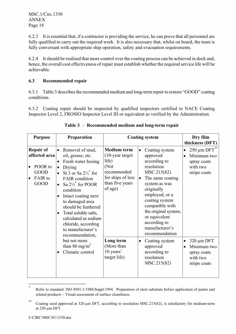
6.2.3 It is essential that, if a contractor is providing the service, he can prove that all personnel are fully qualified to carry out the required work. It is also necessary that, whilst on board, the team is fully conversant with appropriate ship operation, safety and evacuation requirements. 6.2.4 It should be realized that more control over the coating process can be achieved in dock and, hence, the overall cost effectiveness of repair must establish whether the required service life will be achievable. 6.3 Recommended repair 6.3.1 Table 3 describes the recommended medium and long-term repair to restore �GOOD� coating conditions. 6.3.2 Coating repair should be inspected by qualified inspectors certified to NACE Coating Inspector Level 2, FROSIO Inspector Level III or equivalent as verified by the Administration.
Table 3 � Recommended medium and long-term repair
Purpose Preparation Coating system Dry film thickness (DFT)
Medium term (10-year target life) (Not recommended for ships of less than five years of age)
• Coating system approved according to resolution MSC.215(82)
• The same coating system as was originally employed, or a coating system compatible with the original system, or equivalent according to manufacturer�s recommendation
• 250 µm DFT**
• Minimum two spray coats with two stripe coats
Repair of affected area • POOR to
GOOD • FAIR to
GOOD
• Removal of mud, oil, grease, etc.
• Fresh water hosing • Drying • St 3 or Sa 2½* for
FAIR condition • Sa 2½* for POOR
condition • Intact coating next
to damaged area should be feathered
• Total soluble salts, calculated as sodium chloride, according to manufacturer�s recommendation, but not more than 80 mg/m2
• Climatic control
Long term (More than 10 years� target life)
• Coating system approved according to resolution MSC.215(82)
• 320 µm DFT • Minimum two
spray coats with two stripe coats
* Refer to standard: ISO 8501-1:1988/Suppl:1994. Preparation of steel substrate before application of paints and
related products − Visual assessment of surface cleanliness. ** Coating used approved at 320 µm DFT, according to resolution MSC.215(82), is satisfactory for medium-term
at 250 µm DFT.
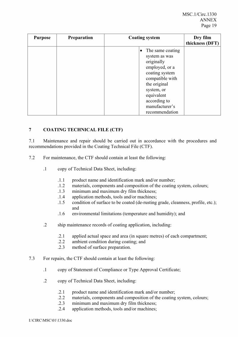
MSC.1/Circ.1330 ANNEX Page 19
I:\CIRC\MSC\01\1330.doc
Purpose Preparation Coating system Dry film thickness (DFT)
• The same coating system as was originally employed, or a coating system compatible with the original system, or equivalent according to manufacturer�s recommendation
7 COATING TECHNICAL FILE (CTF) 7.1 Maintenance and repair should be carried out in accordance with the procedures and recommendations provided in the Coating Technical File (CTF). 7.2 For maintenance, the CTF should contain at least the following:
.1 copy of Technical Data Sheet, including:
.1.1 product name and identification mark and/or number;
.1.2 materials, components and composition of the coating system, colours;
.1.3 minimum and maximum dry film thickness;
.1.4 application methods, tools and/or machines;
.1.5 condition of surface to be coated (de-rusting grade, cleanness, profile, etc.); and
.1.6 environmental limitations (temperature and humidity); and
.2 ship maintenance records of coating application, including:
.2.1 applied actual space and area (in square metres) of each compartment;
.2.2 ambient condition during coating; and
.2.3 method of surface preparation. 7.3 For repairs, the CTF should contain at least the following:
.1 copy of Statement of Compliance or Type Approval Certificate; .2 copy of Technical Data Sheet, including:
.2.1 product name and identification mark and/or number; .2.2 materials, components and composition of the coating system, colours; .2.3 minimum and maximum dry film thickness; .2.4 application methods, tools and/or machines;

MSC.1/Circ.1330 ANNEX Page 20
I:\CIRC\MSC\01\1330.doc
.2.5 condition of surface to be coated (de-rusting grade, cleanness, profile, etc.); and
.2.6 environmental limitations (temperature and humidity);
.3 shipyard work records of coating application, including:
.3.1 applied actual space and area (in square metres) of each compartment;
.3.2 applied coating system;
.3.3 time of coating, thickness, number of layers, etc.;
.3.4 ambient condition during coating; and
.3.5 method of surface preparation;
.4 coating log issued by the coating inspector, stating that the coating was applied in accordance with the specifications to the satisfaction of the coating supplier representative and specifying deviations from the specifications (example of daily log and non-conformity report (see annex 2 to resolution MSC.215(82));
.5 shipyard�s verified inspection report, including:
.5.1 completion date of inspection; .5.2 result of inspection; .5.3 remarks (if given); and .5.4 inspector signature; and
.6 procedures for in-service maintenance and repair of coating system, if different than
original coating system. 8 REFERENCES IACS Recommendation 87 − Guidelines for Coating Maintenance and Repairs for Ballast Tanks and Combined Cargo/Ballast Tanks on Oil Tankers, revision 1, 2006. Note:
1 The above reference is for information purposes only. Although IACS Recommendation 87 has been specifically developed for oil tankers, it contains information that may be useful for other ship types.
2 IACS Recommendation 87 is available to download from the website:
www.iacs.org.uk.
__________