Embed Size (px)
Citation preview
BLADE FEATURES EXPLAINED
2
6
12
3
8
10
11
9
5
13
7
14
20
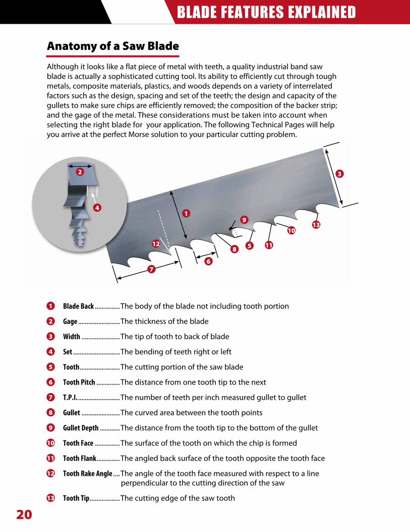
Anatomy of a Saw Blade
Although it looks like a flat piece of metal with teeth, a quality industrial band saw blade is actually a sophisticated cutting tool. Its ability to efficiently cut through tough metals, composite materials, plastics, and woods depends on a variety of interrelated factors such as the design, spacing and set of the teeth; the design and capacity of the gullets to make sure chips are efficiently removed; the composition of the backer strip; and the gage of the metal. These considerations must be taken into account when selecting the right blade for your application. The following Technical Pages will help you arrive at the perfect Morse solution to your particular cutting problem.
BladeBack ...............The body of the blade not including tooth portion
Gage .........................The thickness of the blade
Width .......................The tip of tooth to back of blade
Set ............................The bending of teeth right or left
Tooth ........................The cutting portion of the saw blade
Tooth Pitch ..............The distance from one tooth tip to the next
T.P.I. .........................The number of teeth per inch measured gullet to gullet
Gullet .......................The curved area between the tooth points
GulletDepth ............The distance from the tooth tip to the bottom of the gullet
ToothFace ...............The surface of the tooth on which the chip is formed
ToothFlank ..............The angled back surface of the tooth opposite the tooth face
ToothRakeAngle ....The angle of the tooth face measured with respect to a line perpendicular to the cutting direction of the saw
Tooth Tip ..................The cutting edge of the saw tooth
10
9
8
7
6
5
4
3
2
1
11
12
13
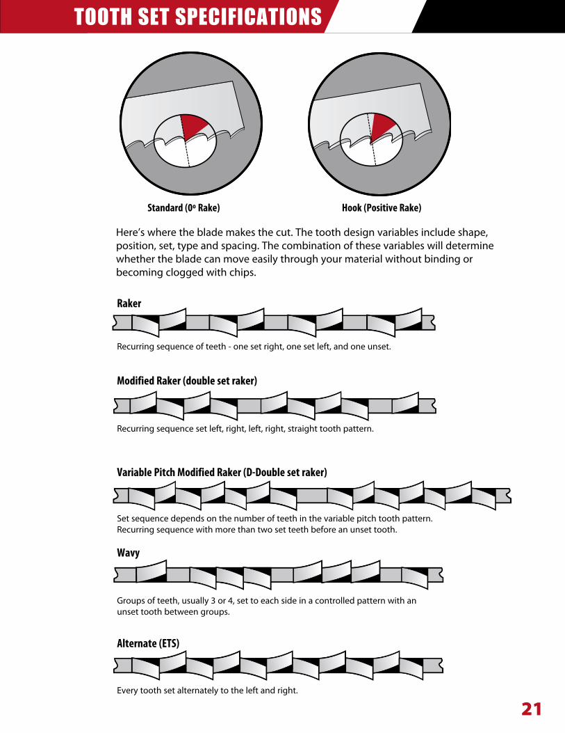
TOOTH SET SPECIFICATIONS
21
Standard(0ºRake) Hook(PositiveRake)
Here’s where the blade makes the cut. The tooth design variables include shape, position, set, type and spacing. The combination of these variables will determine whether the blade can move easily through your material without binding or becoming clogged with chips.
Raker
ModifiedRaker(doublesetraker)
VariablePitchModifiedRaker(D-Doublesetraker)
Alternate(ETS)
Recurring sequence of teeth - one set right, one set left, and one unset.
Recurring sequence set left, right, left, right, straight tooth pattern.
Set sequence depends on the number of teeth in the variable pitch tooth pattern.Recurring sequence with more than two set teeth before an unset tooth.
Groups of teeth, usually 3 or 4, set to each side in a controlled pattern with an unset tooth between groups.
Every tooth set alternately to the left and right.
Wavy
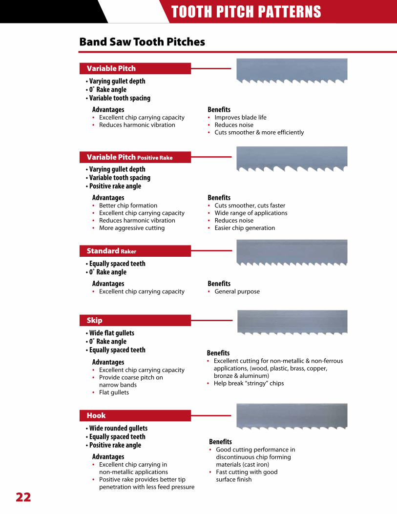
TOOTH PITCH PATTERNS
22
Band Saw Tooth Pitches
•Varyinggulletdepth •Variabletoothspacing•Positiverakeangle
Advantages• Excellent chip carrying capacity
Benefits• General purpose
•Equallyspacedteeth •0˚Rakeangle
Advantages• Excellent chip carrying capacity• Provide coarse pitch on narrow bands• Flat gullets
Benefits• Excellent cutting for non-metallic & non-ferrous
applications, (wood, plastic, brass, copper, bronze & aluminum) • Help break “stringy” chips
•Wideflatgullets•0˚Rakeangle •Equallyspacedteeth
Hook
Advantages• Excellent chip carrying in non-metallic applications• Positive rake provides better tip
penetration with less feed pressure
•Wideroundedgullets•Equallyspacedteeth •Positiverakeangle
Advantages• Excellent chip carrying capacity• Reduces harmonic vibration
Benefits• Improves blade life• Reduces noise• Cuts smoother & more efficiently
•Varyinggulletdepth•0˚Rakeangle •Variabletoothspacing
Advantages• Better chip formation• Excellent chip carrying capacity• Reduces harmonic vibration• More aggressive cutting
Benefits• Cuts smoother, cuts faster• Wide range of applications• Reduces noise• Easier chip generation
Benefits• Good cutting performance in
discontinuous chip forming materials (cast iron)
• Fast cutting with good surface finish
Skip
Standard Raker
Variable Pitch Positive Rake
Variable Pitch
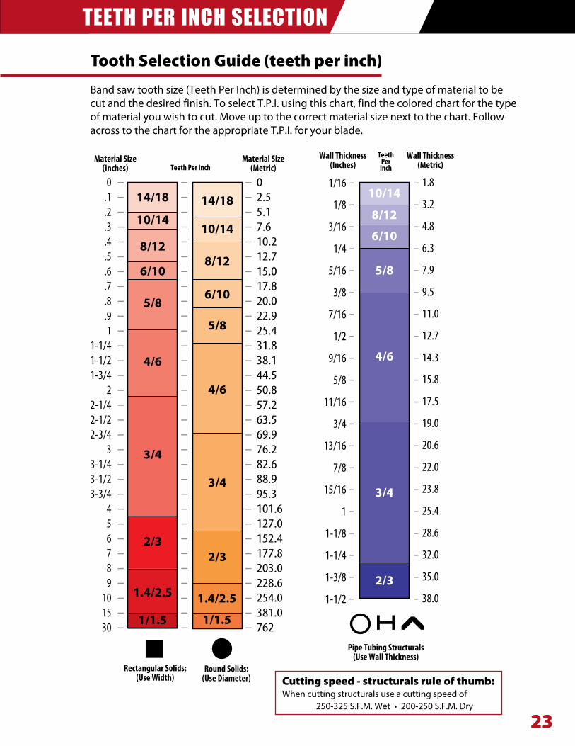
TEETH PER INCH SELECTION
23
Tooth Selection Guide (teeth per inch)
Band saw tooth size (Teeth Per Inch) is determined by the size and type of material to be cut and the desired finish. To select T.P.I. using this chart, find the colored chart for the type of material you wish to cut. Move up to the correct material size next to the chart. Follow across to the chart for the appropriate T.P.I. for your blade.
Cutting speed - structurals rule of thumb:When cutting structurals use a cutting speed of 250-325S.F.M.Wet•200-250S.F.M.Dry
MaterialSize(Inches)
MaterialSize(Metric)
Wall Thickness(Inches)
Wall Thickness(Metric)Teeth Per Inch
Teeth Per
InchIN.0
.1
.2
.3
.4
.5
.6
.7
.8
.91
1-1/41-1/21-3/4
22-1/42-1/22-3/4
33-1/43-1/23-3/4
456789
101530
IN.02.55.17.610.212.715.017.820.022.925.431.838.144.550.857.263.569.976.282.688.995.3101.6127.0152.4177.8203.0228.6254.0381.0762
14/18
10/14
8/12
6/10
5/8
4/6
3/4
2/3
14/18
10/14
8/12
6/10
5/8
4/6
3/4
2/3
10/14
8/12
6/10
5/8
4/6
3/4
2/3
1/16
1/8
3/16
1/4
5/16
3/8
7/16
1/2
9/16
5/8
11/16
3/4
13/16
7/8
15/16
1
1-1/8
1-1/4
1-3/8
1-1/2
1.8
3.2
4.8
6.3
7.9
9.5
11.0
12.7
14.3
15.8
17.5
19.0
20.6
22.0
23.8
25.4
28.6
32.0
35.0
38.01.4/2.5
1/1.5
1.4/2.5
1/1.5
RectangularSolids:(UseWidth)
RoundSolids:(UseDiameter)
PipeTubingStructurals(UseWallThickness)
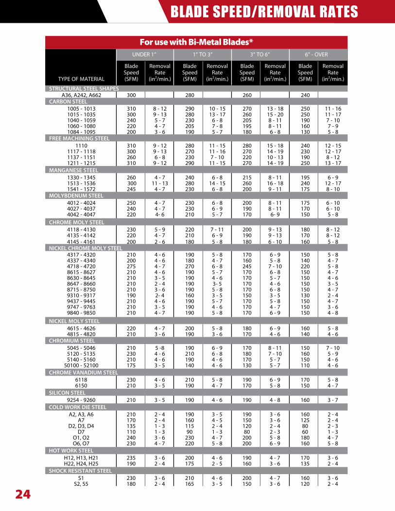
BLADE SPEED/REMOVAL RATES
24
For use with Bi-Metal Blades* UNDER 1” 1” TO 3” 3” TO 6” 6” - OVER
Blade Removal Blade Removal Blade Removal Blade Removal Speed Rate Speed Rate Speed Rate Speed Rate TYPE OF MATERIAL (SFM) (in2/min.) (SFM) (in2/min.) (SFM) (in2/min.) (SFM) (in2/min.)
STRUCTURAL STEEL SHAPES A36, A242, A662 300 280 260 240 CARBON STEEL 1005 - 1013 310 8 - 12 290 10 - 15 270 13 - 18 250 11 - 16 1015 - 1035 300 9 - 13 280 13 - 17 260 15 - 20 250 11 - 17 1040 - 1059 240 5 - 7 230 6 - 8 205 8 - 11 190 7 - 10 1060 - 1080 220 4 - 7 205 7 - 8 195 8 - 11 160 7 - 9 1084 - 1095 200 3 - 6 190 5 - 7 180 6 - 8 130 5 - 8 FREE MACHINING STEEL 1110 310 9 - 12 280 11 - 15 280 15 - 18 240 12 - 15 1117 - 1118 300 9 - 13 270 11 - 16 270 14 - 19 230 12 - 17 1137 - 1151 260 6 - 8 230 7 - 10 220 10 - 13 190 8 - 12 1211 - 1215 310 9 - 12 290 11 - 15 270 14 - 19 250 13 - 17 MANGANESE STEEL 1330 - 1345 260 4 - 7 240 6 - 8 215 8 - 11 195 6 - 9 1513 - 1536 300 11 - 13 280 14 - 15 260 16 - 18 240 12 - 17 1541 - 1572 245 4 - 7 230 6 - 8 200 9 - 11 175 8 - 10 MOLYBDENUM STEEL 4012 - 4024 250 4 - 7 230 6 - 8 200 8 - 11 175 6 - 10 4027 - 4037 240 4 - 7 230 6 - 9 190 8 - 11 170 6 - 10 4042 - 4047 220 4- 6 210 5 - 7 170 6- 9 150 5 - 8 CHROME MOLY STEEL 4118 - 4130 230 5 - 9 220 7 - 11 200 9 - 13 180 8 - 12 4135 - 4142 220 4 - 7 210 6 - 9 190 9 - 13 170 8 - 12 4145 - 4161 200 2 - 6 180 5 - 8 180 6 - 10 160 5 - 8 NICKEL CHROME MOLY STEEL 4317 - 4320 210 4 - 6 190 5 - 8 170 6 - 9 150 5 - 8 4337 - 4340 200 4 - 6 180 4 - 7 160 5 - 8 140 4 - 7 4718 - 4720 275 4 - 7 270 6 - 8 245 7 - 10 220 5 - 8 8615 - 8627 210 4 - 6 190 5 - 7 170 6 - 8 150 4 - 7 8630 - 8645 210 3 - 5 190 4 - 6 170 5 - 7 150 4 - 6 8647 - 8660 210 2 - 4 190 3- 5 170 4 - 6 150 3 - 5 8715 - 8750 210 3 - 6 190 5 - 8 170 6 - 8 150 4 - 7 9310 - 9317 190 2- 4 160 3 - 5 150 3 - 5 130 2 - 4 9437 - 9445 210 4 - 6 190 5 - 7 170 5 - 8 150 4 - 7 9747 - 9763 210 3 - 5 190 4 - 6 170 4 - 7 150 3 - 6 9840 - 9850 210 4 - 7 190 5 - 8 170 6 - 9 150 4 - 8 NICKEL MOLY STEEL 4615 - 4626 220 4 - 7 200 5 - 8 180 6 - 9 160 5 - 8 4815 - 4820 210 3 - 6 190 3 - 6 170 4 - 6 140 4 - 6 CHROMIUM STEEL 5045 - 5046 210 5 -8 190 6 - 9 170 8 - 11 150 7 - 10 5120 - 5135 230 4 - 6 210 6 - 8 180 7 - 10 160 5 - 9 5140 - 5160 210 4 - 6 190 4 - 6 170 5 - 7 150 4 - 6 50100 - 52100 175 3 - 5 140 4 - 6 130 5 - 7 110 4 - 6 CHROME VANADIUM STEEL 6118 230 4 - 6 210 5 - 8 190 6 - 9 170 5 - 8 6150 210 3 - 5 190 4 - 7 170 5 - 8 150 4 - 7 SILICON STEEL 9254 - 9260 210 3 - 5 190 4 - 6 190 4 - 8 160 3 - 7 COLD WORK DIE STEEL A2, A3, A6 210 2 - 4 190 3 - 5 190 3 - 6 160 2 - 4 A7 170 2 - 4 160 4 - 5 150 3 - 6 125 2 - 4 D2, D3, D4 135 1 - 3 115 2 - 4 120 2 - 4 80 2 - 3 D7 110 1 - 3 90 1 - 3 80 2 - 3 60 1 - 3 O1, O2 240 3 - 6 230 4 - 7 200 5 - 8 180 4 - 7 O6, O7 230 4 - 7 220 5 - 8 200 6 - 9 160 5 - 8 HOT WORK STEEL H12, H13, H21 235 3 - 6 200 4 - 6 190 4 - 7 170 3 - 6 H22, H24, H25 190 2 - 4 175 2 - 5 160 3 - 6 135 2 - 4 SHOCK RESISTANT STEEL S1 230 3 - 6 210 4 - 6 200 4 - 7 160 3 - 6 S2, S5 180 2 - 4 165 3 - 5 150 3 - 6 120 2 - 4
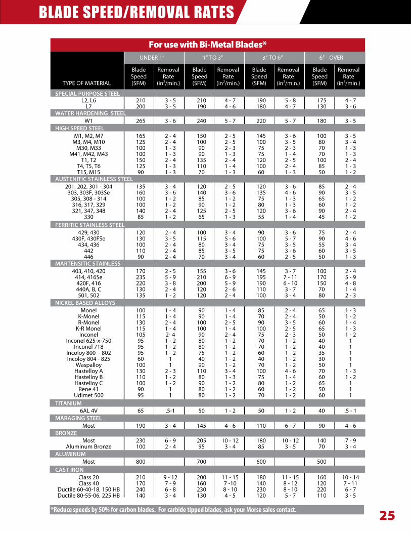
BLADE SPEED/REMOVAL RATES
25
For use with Bi-Metal Blades* UNDER 1” 1” TO 3” 3” TO 6” 6” - OVER
Blade Removal Blade Removal Blade Removal Blade Removal Speed Rate Speed Rate Speed Rate Speed Rate TYPE OF MATERIAL (SFM) (in2/min.) (SFM) (in2/min.) (SFM) (in2/min.) (SFM) (in2/min.)
SPECIAL PURPOSE STEEL L2, L6 210 3 - 5 210 4 - 7 190 5 - 8 175 4 - 7 L7 200 3 - 5 190 4 - 6 180 4 - 7 130 3 - 6 WATER HARDENING STEEL W1 265 3 - 6 240 5 - 7 220 5 - 7 180 3 - 5 HIGH SPEED STEEL M1, M2, M7 165 2 - 4 150 2 - 5 145 3 - 6 100 3 - 5 M3, M4, M10 125 2 - 4 100 2 - 5 100 3 - 5 80 3 - 4 M30, M33 100 1 - 3 90 2 - 3 75 2 - 3 70 1 - 3 M41, M42, M43 100 1 - 3 90 1 - 3 75 1 - 4 70 1 - 3 T1, T2 150 2 - 4 135 2 - 4 120 2 - 5 100 2 - 4 T4, T5, T6 125 1 - 3 110 1 - 4 100 2 - 4 85 1 - 3 T15, M15 90 1 - 3 70 1 - 3 60 1 - 3 50 1 - 2 AUSTENITIC STAINLESS STEEL 201, 202, 301 - 304 135 3 - 4 120 2 - 5 120 3 - 6 85 2 - 4 303, 303F, 303Se 160 3 - 6 140 3 - 6 135 4 - 6 90 3 - 5 305, 308 - 314 100 1 - 2 85 1 - 2 75 1 - 3 65 1 - 2 316, 317, 329 100 1 - 2 90 1 - 2 80 1 - 3 60 1 - 2 321, 347, 348 140 2 - 4 125 2 - 5 120 3 - 6 90 2 - 4 330 85 1 - 2 65 1 - 3 55 1 - 4 45 1 - 2 FERRITIC STAINLESS STEEL 429, 430 120 2 - 4 100 3 - 4 90 3 - 6 75 2 - 4 430F, 430FSe 130 3 - 5 115 5 - 6 100 5 - 7 90 4 - 6 434, 436 100 2 - 4 80 3 - 4 75 3 - 5 55 3 - 4 442 110 2 - 4 85 3 - 5 75 3 - 6 60 3 - 5 446 90 2 - 4 70 3 - 4 60 2 - 5 50 1 - 3 MARTENSITIC STAINLESS 403, 410, 420 170 2 - 5 155 3 - 6 145 3 - 7 100 2 - 4 414, 416Se 235 5 - 9 210 6 - 9 195 7 - 11 170 5 - 9 420F, 416 220 3 - 8 200 5 - 9 190 6 - 10 150 4 - 8 440A, B, C 130 2 - 4 120 2 - 6 110 3 - 7 70 1 - 4 501, 502 135 1 - 2 120 2 - 4 100 3 - 4 80 2 - 3 NICKEL BASED ALLOYS Monel 100 1 - 4 90 1 - 4 85 2 - 4 65 1 - 3 K-Monel 115 1 - 4 90 1 - 4 70 2 - 4 50 1 - 2 R-Monel 130 2 - 4 100 2 - 5 90 3 - 5 60 1 - 4 K-R Monel 115 1 - 4 100 1 - 4 100 2 - 5 65 1 - 3 Inconel 105 2- 4 90 2 - 4 75 2 - 3 50 1 - 2 Inconel 625-x-750 95 1 - 2 80 1 - 2 70 1 - 2 40 1 Inconel 718 95 1 - 2 80 1 - 2 70 1 - 2 40 1 Incoloy 800 - 802 95 1 - 2 75 1 - 2 60 1 - 2 35 1 Incoloy 804 - 825 60 1 40 1 - 2 40 1 - 2 30 1 Waspalloy 100 1 90 1 - 2 70 1 - 2 50 1 Hastelloy A 130 2 - 3 110 3 - 4 100 4 - 6 70 1 - 3 Hastelloy B 110 1 - 2 80 1 - 3 75 1 - 4 60 1 - 2 Hastelloy C 100 1 - 2 90 1 - 2 80 1 - 2 65 1 Rene 41 90 1 80 1 - 2 60 1 - 2 50 1 Udimet 500 95 1 80 1 - 2 70 1 - 2 60 1 TITANIUM 6AL 4V 65 .5-1 50 1 - 2 50 1 - 2 40 .5 - 1 MARAGING STEEL Most 190 3 - 4 145 4 - 6 110 6 - 7 90 4 - 6 BRONZE Most 230 6 - 9 205 10 - 12 180 10 - 12 140 7 - 9 Aluminum Bronze 100 2 - 4 95 3 - 4 85 3 - 5 70 3 - 4 ALUMINUM Most 800 700 600 500 CAST IRON Class 20 210 9 - 12 200 11 - 15 180 11 - 15 160 10 - 14 Class 40 170 7 - 9 160 7 -10 140 8 - 12 120 7 - 11 Ductile 60-40-18, 150 HB 240 6 - 8 230 8 - 10 230 8 - 10 220 6 - 7 Ductile 80-55-06, 225 HB 140 3 - 4 130 4 - 5 120 5 - 7 110 3 - 5
*Reducespeedsby50%forcarbonblades.Forcarbidetippedblades,askyourMorsesalescontact.
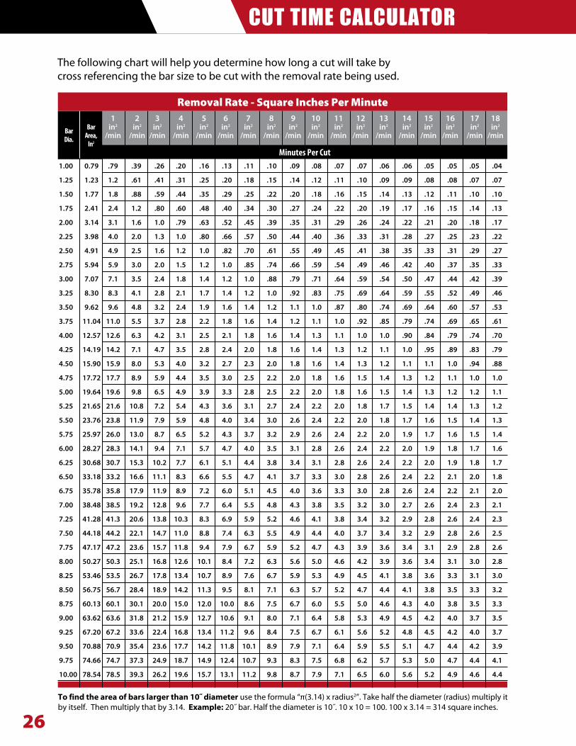
CUT TIME CALCULATOR
26
The following chart will help you determine how long a cut will take by cross referencing the bar size to be cut with the removal rate being used.
1 2 3 4 5 6 7 8 9 10 11 12 13 14 15 16 17 18 in2 in2 in2 in2 in2 in2 in2 in2 in2 in2 in2 in2 in2 in2 in2 in2 in2 in2
/min /min /min /min /min /min /min /min /min /min /min /min /min /min /min /min /min /min
1.00 0.79 .79 .39 .26 .20 .16 .13 .11 .10 .09 .08 .07 .07 .06 .06 .05 .05 .05 .04 1.25 1.23 1.2 .61 .41 .31 .25 .20 .18 .15 .14 .12 .11 .10 .09 .09 .08 .08 .07 .07 1.50 1.77 1.8 .88 .59 .44 .35 .29 .25 .22 .20 .18 .16 .15 .14 .13 .12 .11 .10 .10 1.75 2.41 2.4 1.2 .80 .60 .48 .40 .34 .30 .27 .24 .22 .20 .19 .17 .16 .15 .14 .13 2.00 3.14 3.1 1.6 1.0 .79 .63 .52 .45 .39 .35 .31 .29 .26 .24 .22 .21 .20 .18 .17 2.25 3.98 4.0 2.0 1.3 1.0 .80 .66 .57 .50 .44 .40 .36 .33 .31 .28 .27 .25 .23 .22 2.50 4.91 4.9 2.5 1.6 1.2 1.0 .82 .70 .61 .55 .49 .45 .41 .38 .35 .33 .31 .29 .27 2.75 5.94 5.9 3.0 2.0 1.5 1.2 1.0 .85 .74 .66 .59 .54 .49 .46 .42 .40 .37 .35 .33 3.00 7.07 7.1 3.5 2.4 1.8 1.4 1.2 1.0 .88 .79 .71 .64 .59 .54 .50 .47 .44 .42 .39 3.25 8.30 8.3 4.1 2.8 2.1 1.7 1.4 1.2 1.0 .92 .83 .75 .69 .64 .59 .55 .52 .49 .46 3.50 9.62 9.6 4.8 3.2 2.4 1.9 1.6 1.4 1.2 1.1 1.0 .87 .80 .74 .69 .64 .60 .57 .53 3.75 11.04 11.0 5.5 3.7 2.8 2.2 1.8 1.6 1.4 1.2 1.1 1.0 .92 .85 .79 .74 .69 .65 .61 4.00 12.57 12.6 6.3 4.2 3.1 2.5 2.1 1.8 1.6 1.4 1.3 1.1 1.0 1.0 .90 .84 .79 .74 .70 4.25 14.19 14.2 7.1 4.7 3.5 2.8 2.4 2.0 1.8 1.6 1.4 1.3 1.2 1.1 1.0 .95 .89 .83 .79 4.50 15.90 15.9 8.0 5.3 4.0 3.2 2.7 2.3 2.0 1.8 1.6 1.4 1.3 1.2 1.1 1.1 1.0 .94 .88 4.75 17.72 17.7 8.9 5.9 4.4 3.5 3.0 2.5 2.2 2.0 1.8 1.6 1.5 1.4 1.3 1.2 1.1 1.0 1.0 5.00 19.64 19.6 9.8 6.5 4.9 3.9 3.3 2.8 2.5 2.2 2.0 1.8 1.6 1.5 1.4 1.3 1.2 1.2 1.1 5.25 21.65 21.6 10.8 7.2 5.4 4.3 3.6 3.1 2.7 2.4 2.2 2.0 1.8 1.7 1.5 1.4 1.4 1.3 1.2 5.50 23.76 23.8 11.9 7.9 5.9 4.8 4.0 3.4 3.0 2.6 2.4 2.2 2.0 1.8 1.7 1.6 1.5 1.4 1.3 5.75 25.97 26.0 13.0 8.7 6.5 5.2 4.3 3.7 3.2 2.9 2.6 2.4 2.2 2.0 1.9 1.7 1.6 1.5 1.4 6.00 28.27 28.3 14.1 9.4 7.1 5.7 4.7 4.0 3.5 3.1 2.8 2.6 2.4 2.2 2.0 1.9 1.8 1.7 1.6 6.25 30.68 30.7 15.3 10.2 7.7 6.1 5.1 4.4 3.8 3.4 3.1 2.8 2.6 2.4 2.2 2.0 1.9 1.8 1.7 6.50 33.18 33.2 16.6 11.1 8.3 6.6 5.5 4.7 4.1 3.7 3.3 3.0 2.8 2.6 2.4 2.2 2.1 2.0 1.8 6.75 35.78 35.8 17.9 11.9 8.9 7.2 6.0 5.1 4.5 4.0 3.6 3.3 3.0 2.8 2.6 2.4 2.2 2.1 2.0 7.00 38.48 38.5 19.2 12.8 9.6 7.7 6.4 5.5 4.8 4.3 3.8 3.5 3.2 3.0 2.7 2.6 2.4 2.3 2.1 7.25 41.28 41.3 20.6 13.8 10.3 8.3 6.9 5.9 5.2 4.6 4.1 3.8 3.4 3.2 2.9 2.8 2.6 2.4 2.3 7.50 44.18 44.2 22.1 14.7 11.0 8.8 7.4 6.3 5.5 4.9 4.4 4.0 3.7 3.4 3.2 2.9 2.8 2.6 2.5 7.75 47.17 47.2 23.6 15.7 11.8 9.4 7.9 6.7 5.9 5.2 4.7 4.3 3.9 3.6 3.4 3.1 2.9 2.8 2.6 8.00 50.27 50.3 25.1 16.8 12.6 10.1 8.4 7.2 6.3 5.6 5.0 4.6 4.2 3.9 3.6 3.4 3.1 3.0 2.8 8.25 53.46 53.5 26.7 17.8 13.4 10.7 8.9 7.6 6.7 5.9 5.3 4.9 4.5 4.1 3.8 3.6 3.3 3.1 3.0 8.50 56.75 56.7 28.4 18.9 14.2 11.3 9.5 8.1 7.1 6.3 5.7 5.2 4.7 4.4 4.1 3.8 3.5 3.3 3.2 8.75 60.13 60.1 30.1 20.0 15.0 12.0 10.0 8.6 7.5 6.7 6.0 5.5 5.0 4.6 4.3 4.0 3.8 3.5 3.3 9.00 63.62 63.6 31.8 21.2 15.9 12.7 10.6 9.1 8.0 7.1 6.4 5.8 5.3 4.9 4.5 4.2 4.0 3.7 3.5 9.25 67.20 67.2 33.6 22.4 16.8 13.4 11.2 9.6 8.4 7.5 6.7 6.1 5.6 5.2 4.8 4.5 4.2 4.0 3.7 9.50 70.88 70.9 35.4 23.6 17.7 14.2 11.8 10.1 8.9 7.9 7.1 6.4 5.9 5.5 5.1 4.7 4.4 4.2 3.9 9.75 74.66 74.7 37.3 24.9 18.7 14.9 12.4 10.7 9.3 8.3 7.5 6.8 6.2 5.7 5.3 5.0 4.7 4.4 4.1 10.00 78.54 78.5 39.3 26.2 19.6 15.7 13.1 11.2 9.8 8.7 7.9 7.1 6.5 6.0 5.6 5.2 4.9 4.6 4.4
MinutesPerCut
BarArea,
In2
BarDia.
Removal Rate - Square Inches Per Minute
To find the area of bars larger than 10˝ diameter use the formula “π(3.14) x radius2”. Take half the diameter (radius) multiply it by itself. Then multiply that by 3.14. Example: 20˝ bar. Half the diameter is 10˝. 10 x 10 = 100. 100 x 3.14 = 314 square inches.
METAL CHIP EVALUATION
27
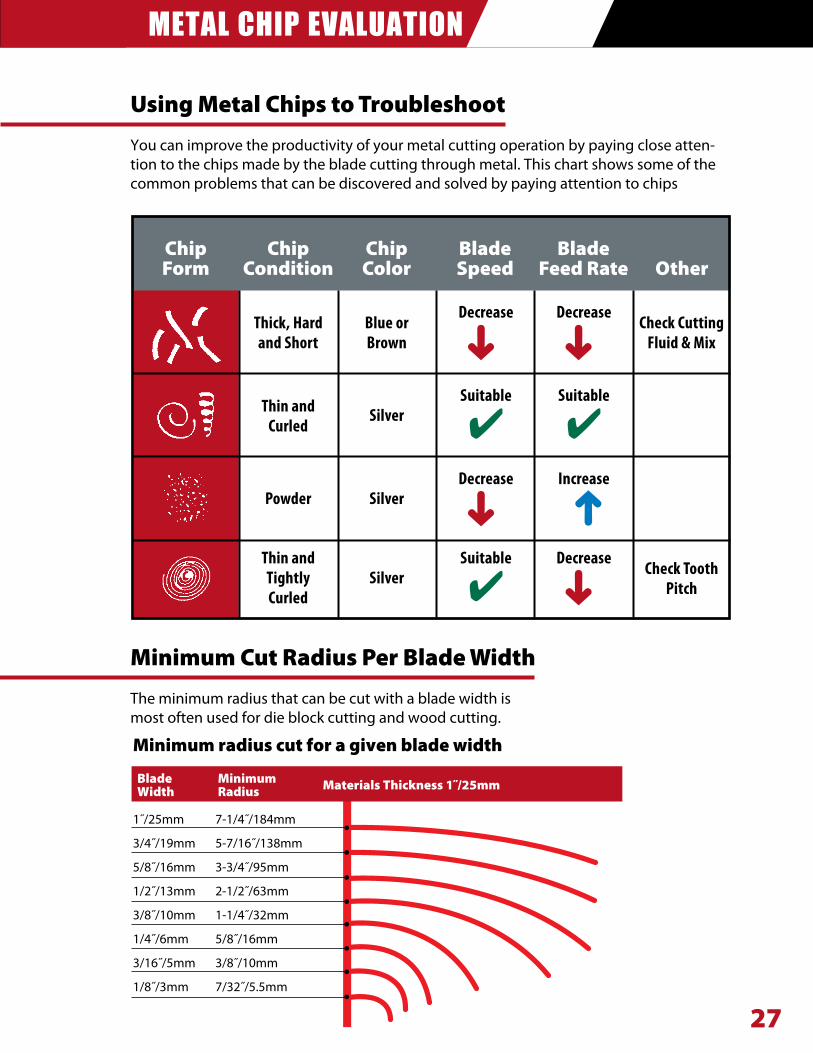
Minimum Cut Radius Per Blade Width
The minimum radius that can be cut with a blade width is most often used for die block cutting and wood cutting.
Minimum radius cut for a given blade width
1˝/25mm 7-1/4˝/184mm
3/4˝/19mm 5-7/16˝/138mm
5/8˝/16mm 3-3/4˝/95mm
1/2˝/13mm 2-1/2˝/63mm
3/8˝/10mm 1-1/4˝/32mm
1/4˝/6mm 5/8˝/16mm
3/16˝/5mm 3/8˝/10mm
1/8˝/3mm 7/32˝/5.5mm
Blade Minimum Materials Thickness 1˝/25mm Width Radius
Using Metal Chips to Troubleshoot
You can improve the productivity of your metal cutting operation by paying close atten-tion to the chips made by the blade cutting through metal. This chart shows some of the common problems that can be discovered and solved by paying attention to chips
ChipForm
ChipCondition
Thick,HardandShort
BlueorBrown
Decrease DecreaseCheckCuttingFluid&Mix
Thin andCurled
SilverSuitable
�Suitable
�
Powder SilverDecrease Increase
Thin andTightlyCurled
SilverSuitable
�Decrease
CheckToothPitch
ChipColor
BladeSpeed
BladeFeed Rate Other
�
� �
�
�
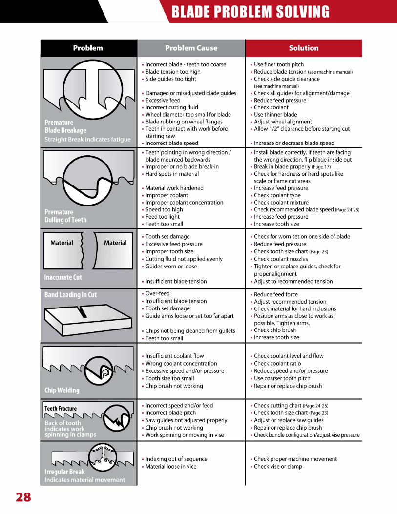
BLADE PROBLEM SOLVING
28
Problem Cause SolutionProblem
IrregularBreakIndicates material movement
TeethFracture
Back of tooth indicates work spinning in clamps
ChipWelding
InaccurateCut
Premature DullingofTeeth
Premature BladeBreakageStraight Break indicates fatigue
BandLeadinginCut
Material Material
• Incorrect blade - teeth too coarse• Blade tension too high• Side guides too tight
• Damaged or misadjusted blade guides• Excessive feed • Incorrect cutting fluid • Wheel diameter too small for blade • Blade rubbing on wheel flanges • Teeth in contact with work before starting saw• Incorrect blade speed
• Teeth pointing in wrong direction / blade mounted backwards
• Improper or no blade break-in• Hard spots in material
• Material work hardened • Improper coolant• Improper coolant concentration• Speed too high• Feed too light• Teeth too small
• Use finer tooth pitch• Reduce blade tension (see machine manual)• Check side guide clearance
(see machine manual)• Check all guides for alignment/damage• Reduce feed pressure• Check coolant• Use thinner blade• Adjust wheel alignment• Allow 1/2” clearance before starting cut
• Increase or decrease blade speed
• Check for worn set on one side of blade• Reduce feed pressure• Check tooth size chart (Page 23)• Check coolant nozzles• Tighten or replace guides, check for proper alignment• Adjust to recommended tension
• Reduce feed force• Adjust recommended tension• Check material for hard inclusions• Position arms as close to work as
possible. Tighten arms.• Check chip brush• Increase tooth size
• Check coolant level and flow• Check coolant ratio• Reduce speed and/or pressure• Use coarser tooth pitch• Repair or replace chip brush
• Check cutting chart (Page 24-25)• Check tooth size chart (Page 23)• Adjust or replace saw guides• Repair or replace chip brush• Check bundle configuration/adjust vise pressure
• Check proper machine movement• Check vise or clamp
• Tooth set damage • Excessive feed pressure • Improper tooth size• Cutting fluid not applied evenly • Guides worn or loose
• Insufficient blade tension
• Over-feed • Insufficient blade tension • Tooth set damage • Guide arms loose or set too far apart • Chips not being cleaned from gullets • Teeth too small
• Insufficient coolant flow • Wrong coolant concentration • Excessive speed and/or pressure• Tooth size too small • Chip brush not working
• Incorrect speed and/or feed• Incorrect blade pitch • Saw guides not adjusted properly• Chip brush not working• Work spinning or moving in vise
• Indexing out of sequence• Material loose in vice
• Install blade correctly. If teeth are facing the wrong direction, flip blade inside out
• Break in blade properly (Page 17)• Check for hardness or hard spots like
scale or flame cut areas• Increase feed pressure• Check coolant type• Check coolant mixture• Check recommended blade speed (Page 24-25)• Increase feed pressure• Increase tooth size
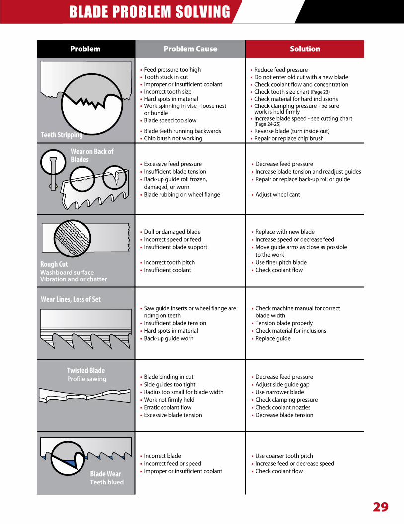
BLADE PROBLEM SOLVING
29
Problem Cause SolutionProblem
BladeWearTeeth blued
TwistedBladeProfile sawing
WearLines,LossofSet
RoughCutWashboard surfaceVibration and or chatter
WearonBackofBlades
TeethStripping
• Feed pressure too high • Tooth stuck in cut• Improper or insufficient coolant• Incorrect tooth size • Hard spots in material• Work spinning in vise - loose nest or bundle• Blade speed too slow
• Blade teeth running backwards • Chip brush not working
• Excessive feed pressure • Insufficient blade tension • Back-up guide roll frozen,
damaged, or worn• Blade rubbing on wheel flange
• Decrease feed pressure• Increase blade tension and readjust guides• Repair or replace back-up roll or guide
• Adjust wheel cant
• Dull or damaged blade • Incorrect speed or feed • Insufficient blade support
• Incorrect tooth pitch • Insufficient coolant
• Replace with new blade• Increase speed or decrease feed• Move guide arms as close as possible to the work• Use finer pitch blade• Check coolant flow
• Saw guide inserts or wheel flange are riding on teeth
• Insufficient blade tension • Hard spots in material • Back-up guide worn
• Check machine manual for correct blade width• Tension blade properly• Check material for inclusions • Replace guide
• Blade binding in cut • Side guides too tight • Radius too small for blade width • Work not firmly held • Erratic coolant flow • Excessive blade tension
• Decrease feed pressure• Adjust side guide gap• Use narrower blade• Check clamping pressure• Check coolant nozzles• Decrease blade tension
• Incorrect blade • Incorrect feed or speed • Improper or insufficient coolant
• Use coarser tooth pitch• Increase feed or decrease speed• Check coolant flow
• Reduce feed pressure• Do not enter old cut with a new blade• Check coolant flow and concentration• Check tooth size chart (Page 23)• Check material for hard inclusions• Check clamping pressure - be sure work is held firmly• Increase blade speed - see cutting chart (Page 24-25)• Reverse blade (turn inside out)• Repair or replace chip brush