Embed Size (px)
Citation preview
a
Blackfin®/SHARC® USBEZ-Extender® Manual
Revision 1.1, July 2012
Part Number82-000224-01
Analog Devices, Inc.One Technology WayNorwood, Mass. 02062-9106

Copyright Information© 2012 Analog Devices, Inc., ALL RIGHTS RESERVED. This docu-ment may not be reproduced in any form without prior, express written consent from Analog Devices, Inc.
Printed in the USA.
DisclaimerAnalog Devices, Inc. reserves the right to change this product without prior notice. Information furnished by Analog Devices is believed to be accurate and reliable. However, no responsibility is assumed by Analog Devices for its use; nor for any infringement of patents or other rights of third parties which may result from its use. No license is granted by impli-cation or otherwise under the patent rights of Analog Devices, Inc.
Trademark and Service Mark NoticeThe Analog Devices logo, Blackfin, CrossCore, EngineerZone, EZ-Board, EZ-Extender, SHARC, and VisualDSP++ are registered trademarks of Analog Devices, Inc.
All other brand and product names are trademarks or service marks of their respective owners.

Regulatory Compliance The Blackfin/SHARC USB EZ-Extender is designed to be used solely in a laboratory environment. The board is not intended for use as a consumer end product or as a portion of a consumer end product. The board is an open system design which does not include a shielded enclosure and there-fore may cause interference to other electrical devices in close proximity. This board should not be used in or near any medical equipment or RF devices.
The Blackfin/SHARC USB EZ-Extender is currently being processed for certification that it complies with the essential requirements of the Euro-pean EMC directive 89/336/EEC amended by 93/68/EEC and therefore carries the “CE” mark.
The Blackfin/SHARC USB EZ-Extender board contains ESD (electrostatic discharge) sensitive devices. Electrostatic charges readily accumulate on the human body and equipment and can discharge without detection. Perma-nent damage may occur on devices subjected to high-energy discharges. Proper ESD precautions are recommended to avoid performance degrada-tion or loss of functionality. Store unused extender boards in the protective shipping package.

Blackfin/SHARC USB EZ-Extender Manual v
CONTENTS
PREFACE
Product Overview ....................................................................... viii
Purpose of This Manual ................................................................ ix
Intended Audience ........................................................................ ix
Manual Contents ........................................................................... x
What’s New in This Manual ........................................................... x
Technical Support ......................................................................... xi
Supported Products ...................................................................... xii
Product Information .................................................................... xii
Analog Devices Web Site ........................................................ xii
EngineerZone ........................................................................ xiii
Related Documents ...................................................................... xiv
BLACKFIN/SHARC USB EZ-EXTENDER INTERFACES
Blackfin/SHARC USB EZ-Extender Setup .................................... 1-1
USB Software ......................................................................... 1-2
USB 2.0 Interface ......................................................................... 1-2
Contents
vi Blackfin/SHARC USB EZ-Extender Manual
BLACKFIN/SHARC USB EZ-EXTENDER HARDWARE REFERENCE
System Architecture ...................................................................... 2-2
Jumper Settings ............................................................................ 2-2
USB Chip Select Jumper (JP1) ................................................ 2-3
USB IRQ Jumper (JP2) ........................................................... 2-3
USB Soft Reset Jumper (JP3) .................................................. 2-3
BLACKFIN/SHARC USB EZ-EXTENDER BILL OF MATERIALS
BLACKFIN/SHARC USB EZ-EXTENDER SCHEMATIC
INDEX
Blackfin/SHARC USB EZ-Extender Manual vii
PREFACE
Thank you for purchasing the Blackfin/SHARC USB EZ-Extender®, Analog Devices, Inc. extender board to the EZ-Board® evaluation system for the ADSP-BF518F, ADSP-BF526 Blackfin®, and ADSP-21469 SHARC® processors.
Blackfin processors are embedded processors that support a Media Instruction Set Computing (MISC) architecture. This architecture is the natural merging of RISC, media functions, and digital signal processing characteristics towards delivering signal processing performance in a microprocessor-like environment.
SHARC processors are based on a 32-bit super Harvard architecture that includes a unique memory architecture comprised of two large on-chip, dual-ported SRAM blocks coupled with a sophisticated IO processor, which gives a SHARC processor the bandwidth for sustained high-speed computations. SHARC processors represents today’s de facto standard for floating-point processing, targeted toward premium audio applications.
The EZ-Board and Blackfin/SHARC USB EZ-Extender are designed to be used in conjunction with the CrossCore® Embedded Studio (CCES) and VisualDSP++® software development environments. The develop-ment environment facilitates advanced application code development and debug, such as:
• Create, compile, assemble, and link application programs written in C++, C, and Blackfin/SHARC USB EZ-Extender assembly
• Load, run, step, halt, and set breakpoints in application programs
Product Overview
viii Blackfin/SHARC USB EZ-Extender Manual
• Read and write data and program memory
• Read and write core and peripheral registers
• Plot memory
To learn more about Analog Devices development software, go to http://www.analog.com/processors/tools.
Product OverviewThe Blackfin/SHARC USB EZ-Extender is a separately sold extender board that plugs onto the expansion interface of the ADSP-BF518F, ADSP-BF526, and ADSP-21469 EZ-Board evaluation systems. The extender board aids the design and prototyping phases of the ADSP-BF518F, ADSP-BF526, and ADSP-21469 processor targeted applications.
The board extends the capabilities of the evaluation system by providing a connection between the asynchronous memory bus of the Black-fin/SHARC processor and a USB 2.0 device.
Please visit www.analog.com/EX2-USB for additional information, includ-ing CCES support.
The following is a list of the Blackfin/SHARC USB EZ-Extender interfaces.
• USB 2.0 interface:
• PLX Technology NET2272 device
• USB driver and application code
• No power supply required: derives power from the EZ-Board
• CE certified
Blackfin/SHARC USB EZ-Extender Manual ix
Preface
Before using any of the interfaces, follow the setup procedure in “Black-fin/SHARC USB EZ-Extender Setup” on page 1-1.
Example programs are available to demonstrate capabilities of the Black-fin/SHARC USB EZ-Extender board.
Purpose of This ManualThe Blackfin/SHARC USB EZ-Extender Manual provides instructions for installing the product hardware (board). The text describes operation and configuration of the board components. Finally, a schematic and a bill of materials are provided as a reference for future designs.
Intended AudienceThe primary audience for this manual is a programmer who is familiar with Analog Devices processors. This manual assumes that the audience has a working knowledge of the appropriate processor architecture and instruction set.
Programmers who are unfamiliar with Analog Devices processors can use this manual but should supplement it with other texts that describe your target architecture. For the locations of these documents, see “Related Documents”.
Programmers who are unfamiliar with CCES or VisualDSP++ should refer to the online help and user’s manuals.
Manual Contents
x Blackfin/SHARC USB EZ-Extender Manual
Manual ContentsThe manual consists of:
• Chapter 1, “Blackfin/SHARC USB EZ-Extender Interfaces” on page 1-1Provides basic board information.
• Chapter 2, “Blackfin/SHARC USB EZ-Extender Hardware Refer-ence” on page 2-1Provides information on the hardware aspects of the board.
• Appendix A, “Blackfin/SHARC USB EZ-Extender Bill of Materi-als” on page A-1Provides a list of components used to manufacture the EZ-Extender board.
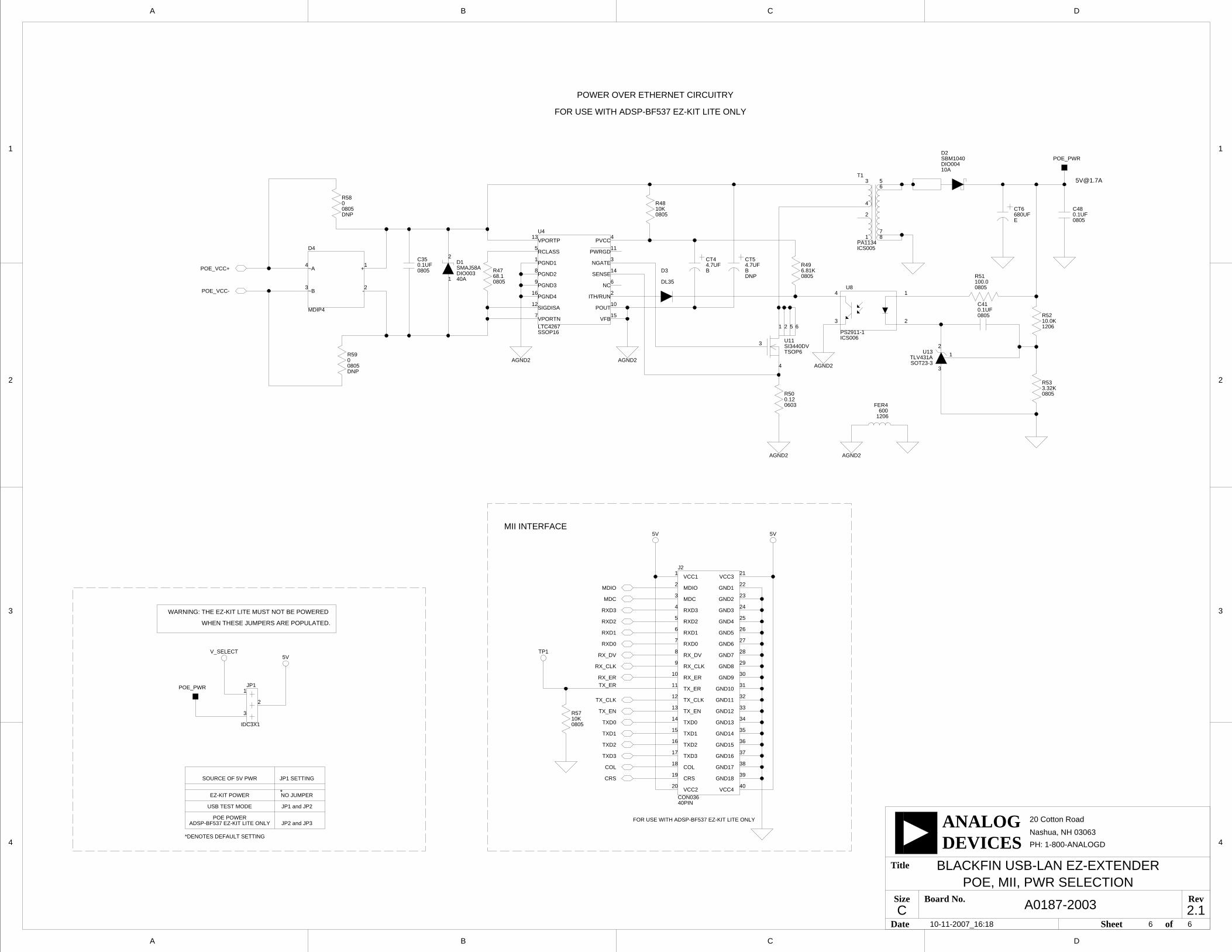
• Appendix B, “Blackfin/SHARC USB EZ-Extender Schematic” on page B-1Provides the resources to allow EZ-Board board-level debugging or to use as a reference design.
What’s New in This ManualThis is revision 1.1 of the Blackfin/SHARC USB EZ-Extender Manual. The manual has been updated to include CCES information. In addition, modifications and corrections based on errata reports against the previous manual revision have been made.
For the latest version of this manual, please refer to the Analog Devices Web site.
Blackfin/SHARC USB EZ-Extender Manual xi
Preface
Technical SupportYou can reach Analog Devices processors and DSP technical support in the following ways:
• Post your questions in the processors and DSP support community at EngineerZone®:http://ez.analog.com/community/dsp
• Submit your questions to technical support directly at:http://www.analog.com/support
• E-mail your questions about processors, DSPs, and tools develop-ment software from CrossCore Embedded Studio or VisualDSP++:
Choose Help > Email Support. This creates an e-mail [email protected] and automatically attaches your CrossCore Embedded Studio or VisualDSP++ version infor-mation and license.dat file.
• E-mail your questions about processors and processor applications to: [email protected] [email protected] (Greater China support)
• In the USA only, call 1-800-ANALOGD (1-800-262-5643)
• Contact your Analog Devices sales office or authorized distributor. Locate one at:www.analog.com/adi-sales

Supported Products
xii Blackfin/SHARC USB EZ-Extender Manual
• Send questions by mail to:Processors and DSP Technical SupportAnalog Devices, Inc.Three Technology WayP.O. Box 9106Norwood, MA 02062-9106USA
Supported ProductsThe Blackfin/SHARC USB EZ-Extender is designed as an extender board to the ADSP-BF518F, ADSP-BF526, and ADSP-21469 EZ-Board evalua-tion systems.
Product InformationProduct information can be obtained from the Analog Devices Web site and the online help.
Analog Devices Web SiteThe Analog Devices Web site, www.analog.com, provides information about a broad range of products—analog integrated circuits, amplifiers, converters, and digital signal processors.
To access a complete technical library for each processor family, go to http://www.analog.com/processors/technical_library. The manuals selection opens a list of current manuals related to the product as well as a link to the previous revisions of the manuals. When locating your manual title, note a possible errata check mark next to the title that leads to the current correction report against the manual.
Blackfin/SHARC USB EZ-Extender Manual xiii
Preface
Also note, MyAnalog is a free feature of the Analog Devices Web site that allows customization of a Web page to display only the latest information about products you are interested in. You can choose to receive weekly e-mail notifications containing updates to the Web pages that meet your interests, including documentation errata against all manuals. MyAnalog provides access to books, application notes, data sheets, code examples, and more.
Visit MyAnalog to sign up. If you are a registered user, just log on. Your user name is your e-mail address.
EngineerZoneEngineerZone is a technical support forum from Analog Devices. It allows you direct access to ADI technical support engineers. You can search FAQs and technical information to get quick answers to your embedded processing and DSP design questions.
Use EngineerZone to connect with other DSP developers who face similar design challenges. You can also use this open forum to share knowledge and collaborate with the ADI support team and your peers. Visit http://ez.analog.com to sign up.
Related Documents
xiv Blackfin/SHARC USB EZ-Extender Manual
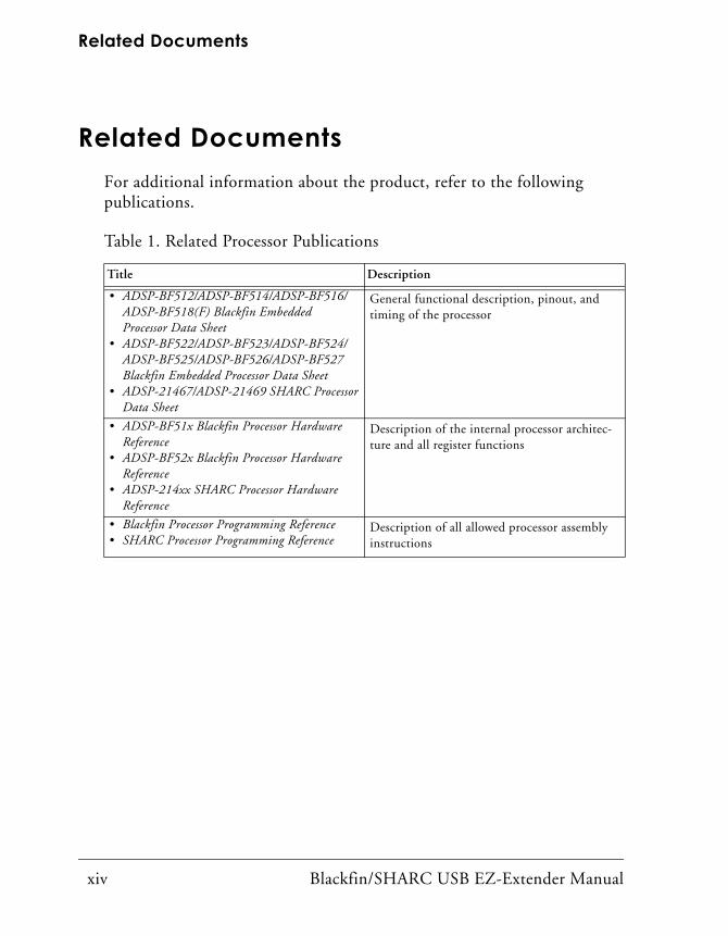
Related DocumentsFor additional information about the product, refer to the following publications.
Table 1. Related Processor Publications
Title Description
• ADSP-BF512/ADSP-BF514/ADSP-BF516/ ADSP-BF518(F) Blackfin Embedded Processor Data Sheet
• ADSP-BF522/ADSP-BF523/ADSP-BF524/ ADSP-BF525/ADSP-BF526/ADSP-BF527 Blackfin Embedded Processor Data Sheet
• ADSP-21467/ADSP-21469 SHARC Processor Data Sheet
General functional description, pinout, and timing of the processor
• ADSP-BF51x Blackfin Processor Hardware Reference
• ADSP-BF52x Blackfin Processor Hardware Reference
• ADSP-214xx SHARC Processor Hardware Reference
Description of the internal processor architec-ture and all register functions
• Blackfin Processor Programming Reference• SHARC Processor Programming Reference
Description of all allowed processor assembly instructions
Blackfin/SHARC USB EZ-Extender Manual 1-1
1 BLACKFIN/SHARC USB EZ-EXTENDER INTERFACES
This chapter provides the setup procedures for both the Blackfin/SHARC USB EZ-Extender and EZ-Board (ADSP-BF518F, ADSP-BF526, or ADSP-21469) and describes the interfaces the extender supports.
The information is presented in the following order.
• “Blackfin/SHARC USB EZ-Extender Setup” on page 1-1
• “USB 2.0 Interface” on page 1-2
Blackfin/SHARC USB EZ-Extender SetupIt is very important to set up all components of the system containing the Blackfin/SHARC USB EZ-Extender, then apply power to the system. The following procedure is recommended for correct setup.
Power your system after these steps are completed:
1. Read the applicable design interface section in this chapter—the text provides an overview of the interface capabilities.
2. Read “System Architecture” on page 2-2 to understand physical connections of the extender board. For detailed information, refer to “Blackfin/SHARC USB EZ-Extender Schematic” on page B-1.
3. Set the jumpers on the Blackfin/SHARC USB EZ-Extender board. Use the block diagram in Figure 2-1 on page 2-2 in conjunction with “Jumper Settings” on page 2-2.
USB 2.0 Interface
1-2 Blackfin/SHARC USB EZ-Extender Manual
4. Set the switches and jumpers on the EZ-Board. If not already, familiarize yourself with the EZ-Board documentation and sche-matic drawings (see “Product Information”).
Compare the expansion interface signals of the Blackfin/SHARC USB EZ-Extender board with the EZ-Board signals to ensure there is no contention. For example, it may be necessary to disable other devices connected to the expansion interface of the processor and disable peripherals on the EZ-Board.
5. Install the Blackfin/SHARC USB EZ-Extender on the EZ-Board via the high speed expansion interface.
USB SoftwareFor information about USB software, refer to the readme text files in the Examples folder of the installation directory.
USB 2.0 InterfaceThe Blackfin/SHARC USB EZ-Extender enables a connection between a USB 2.0 chip and Blackfin/SHARC processor without any other pro-grammable logic. The PLX Technology’s NET2272 controller ties directly to the asynchronous memory bus of the Blackfin or SHARC processor. You can read from and write to the USB 2.0 controller by addressing the named memory bank directly.
You can reset the NET2272 controller by asserting LOW one of the four GPIO signals of the expansion interface. Refer to the appropriate EZ-Board manual to learn how the GPIO signals connect to the processor.
The USB IRQ signal of the NET2272 controller connects to one of the four GPIO signals on the expansion interface. Refer to the appropriate
Blackfin/SHARC USB EZ-Extender Manual 1-3
Blackfin/SHARC USB EZ-Extender Interfaces
EZ-Board document to learn how the GPIO signals connect to the processor.
The USB CS signal of the NET2272 controller connects to one of the four AMS signals on the expansion interface. Refer to the appropriate EZ-Board manual to learn how the AMS signals connect to the processor.
The jumper settings required for each of the respective EZ-Boards are described in the readme text files in the Examples folder of the installation directory. The readme file describes the USB software, source code, driv-ers, and explains how to run a USB-based application.

USB 2.0 Interface
1-4 Blackfin/SHARC USB EZ-Extender Manual
Blackfin/SHARC USB EZ-Extender Manual 2-1
2 BLACKFIN/SHARC USB EZ-EXTENDER HARDWARE REFERENCE
This chapter describes the hardware design of the Blackfin/SHARC USB EZ-Extender.
The following topics are covered.
• “System Architecture” on page 2-2Describes the board configuration and explains how the board components interface with the processor and EZ-Board.
• “Jumper Settings” on page 2-2Describes the on-board configuration jumpers.
System Architecture
2-2 Blackfin/SHARC USB EZ-Extender Manual
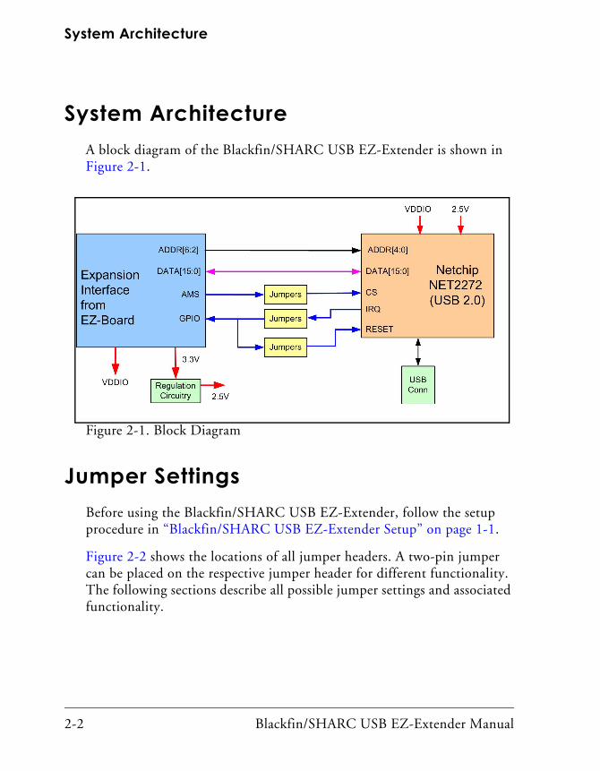
System ArchitectureA block diagram of the Blackfin/SHARC USB EZ-Extender is shown in Figure 2-1.
Jumper SettingsBefore using the Blackfin/SHARC USB EZ-Extender, follow the setup procedure in “Blackfin/SHARC USB EZ-Extender Setup” on page 1-1.
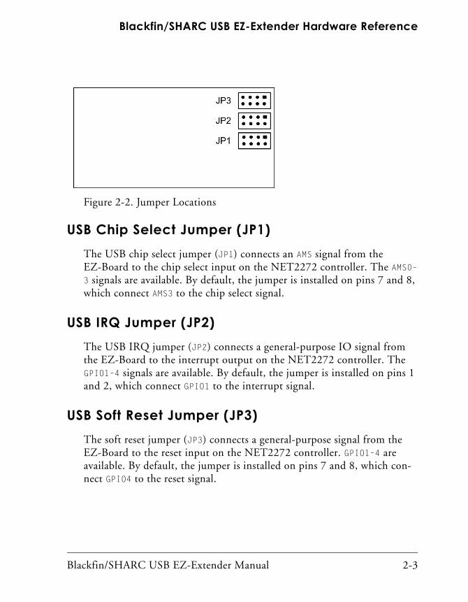
Figure 2-2 shows the locations of all jumper headers. A two-pin jumper can be placed on the respective jumper header for different functionality. The following sections describe all possible jumper settings and associated functionality.
Figure 2-1. Block Diagram
Blackfin/SHARC USB EZ-Extender Manual 2-3
Blackfin/SHARC USB EZ-Extender Hardware Reference
USB Chip Select Jumper (JP1)The USB chip select jumper (JP1) connects an AMS signal from the EZ-Board to the chip select input on the NET2272 controller. The AMS0–
3 signals are available. By default, the jumper is installed on pins 7 and 8, which connect AMS3 to the chip select signal.
USB IRQ Jumper (JP2)The USB IRQ jumper (JP2) connects a general-purpose IO signal from the EZ-Board to the interrupt output on the NET2272 controller. The GPIO1–4 signals are available. By default, the jumper is installed on pins 1 and 2, which connect GPIO1 to the interrupt signal.
USB Soft Reset Jumper (JP3)The soft reset jumper (JP3) connects a general-purpose signal from the EZ-Board to the reset input on the NET2272 controller. GPIO1–4 are available. By default, the jumper is installed on pins 7 and 8, which con-nect GPIO4 to the reset signal.
Figure 2-2. Jumper Locations
Jumper Settings
2-4 Blackfin/SHARC USB EZ-Extender Manual
Blackfin/SHARC USB EZ-Extender Manual A-1
A BLACKFIN/SHARC USB EZ-EXTENDER BILL OF MATERIALS
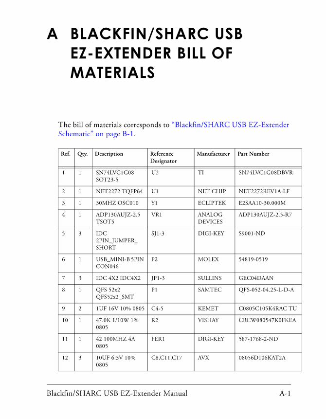
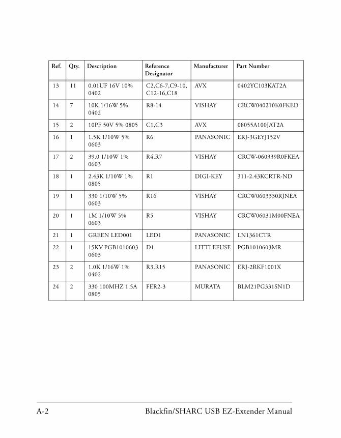
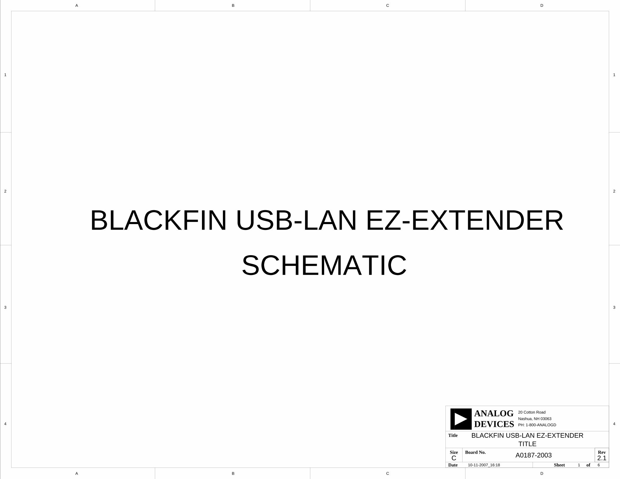
The bill of materials corresponds to “Blackfin/SHARC USB EZ-Extender Schematic” on page B-1.
Ref. Qty. Description Reference Designator
Manufacturer Part Number
1 1 SN74LVC1G08 SOT23-5
U2 TI SN74LVC1G08DBVR
2 1 NET2272 TQFP64 U1 NET CHIP NET2272REV1A-LF
3 1 30MHZ OSC010 Y1 ECLIPTEK E2SAA10-30.000M
4 1 ADP130AUJZ-2.5 TSOT5
VR1 ANALOG DEVICES
ADP130AUJZ-2.5-R7
5 3 IDC 2PIN_JUMPER_SHORT
SJ1-3 DIGI-KEY S9001-ND
6 1 USB_MINI-B 5PIN CON046
P2 MOLEX 54819-0519
7 3 IDC 4X2 IDC4X2 JP1-3 SULLINS GEC04DAAN
8 1 QFS 52x2 QFS52x2_SMT
P1 SAMTEC QFS-052-04.25-L-D-A
9 2 1UF 16V 10% 0805 C4-5 KEMET C0805C105K4RAC TU
10 1 47.0K 1/10W 1% 0805
R2 VISHAY CRCW080547K0FKEA
11 1 42 100MHZ 4A 0805
FER1 DIGI-KEY 587-1768-2-ND
12 3 10UF 6.3V 10% 0805
C8,C11,C17 AVX 08056D106KAT2A
A-2 Blackfin/SHARC USB EZ-Extender Manual
13 11 0.01UF 16V 10% 0402
C2,C6-7,C9-10,C12-16,C18
AVX 0402YC103KAT2A
14 7 10K 1/16W 5% 0402
R8-14 VISHAY CRCW040210K0FKED
15 2 10PF 50V 5% 0805 C1,C3 AVX 08055A100JAT2A
16 1 1.5K 1/10W 5% 0603
R6 PANASONIC ERJ-3GEYJ152V
17 2 39.0 1/10W 1% 0603
R4,R7 VISHAY CRCW-060339R0FKEA
18 1 2.43K 1/10W 1% 0805
R1 DIGI-KEY 311-2.43KCRTR-ND
19 1 330 1/10W 5% 0603
R16 VISHAY CRCW0603330RJNEA
20 1 1M 1/10W 5% 0603
R5 VISHAY CRCW06031M00FNEA
21 1 GREEN LED001 LED1 PANASONIC LN1361CTR
22 1 15KV PGB1010603 0603
D1 LITTLEFUSE PGB1010603MR
23 2 1.0K 1/16W 1% 0402
R3,R15 PANASONIC ERJ-2RKF1001X
24 2 330 100MHZ 1.5A 0805
FER2-3 MURATA BLM21PG331SN1D
Ref. Qty. Description Reference Designator
Manufacturer Part Number
D
4
3
2
1
A B C
20 Cotton Road
Nashua, NH 03063
A B C D
4
3
2
1
PH: 1-800-ANALOGD
C
Title
Size Board No.
Date Sheet of
DEVICESANALOG
RevA0187-2003
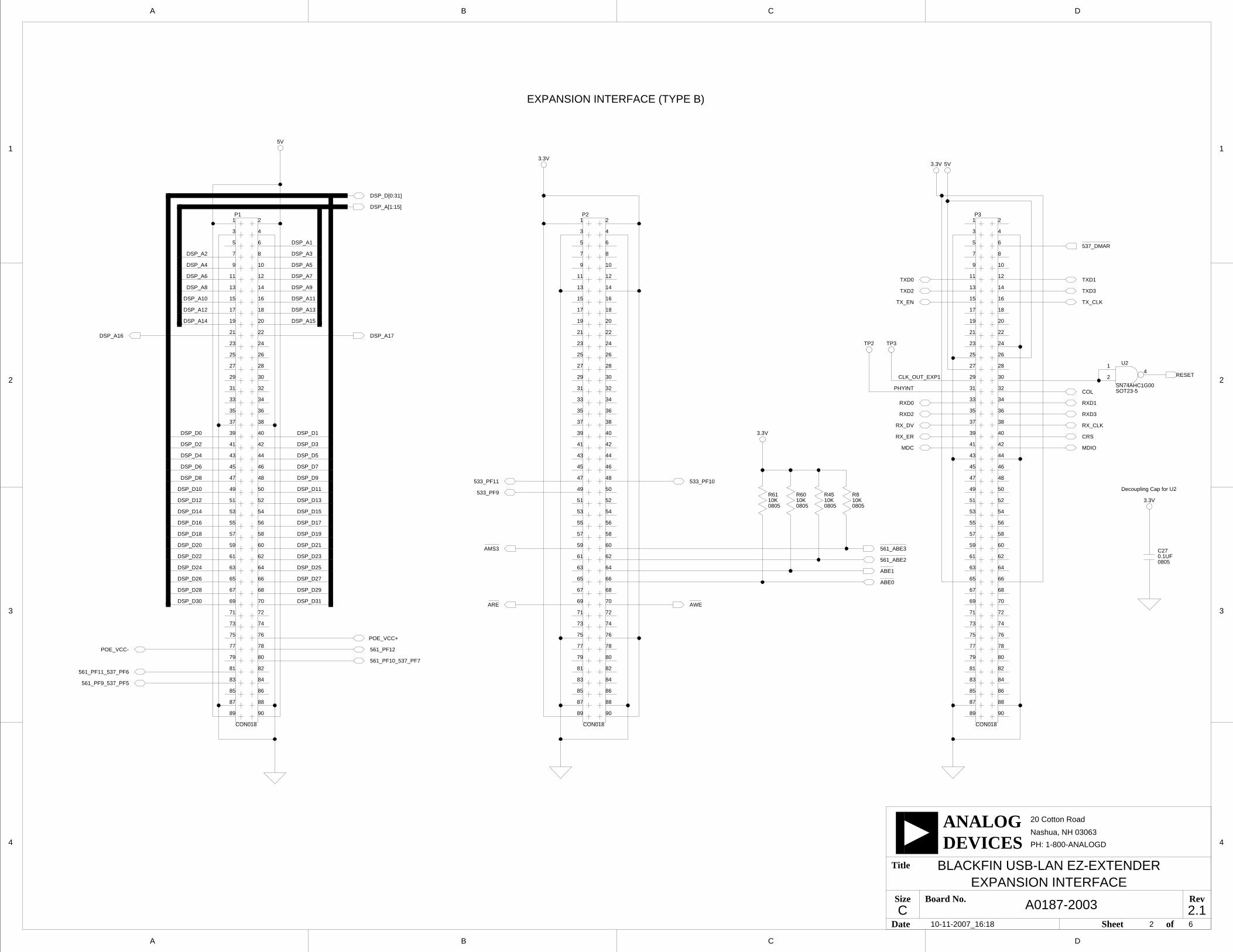
BLACKFIN USB-LAN EZ-EXTENDER
2.1
BLACKFIN USB-LAN EZ-EXTENDER
SCHEMATIC
10-11-2007_16:18 61
TITLE
5V
3.3V
3.3V
D
4
3
2
1
A B C
20 Cotton Road
Nashua, NH 03063
A B C D
4
3
2
1
PH: 1-800-ANALOGD
C
Title
Size Board No.
Date Sheet of
DEVICESANALOG
RevA0187-2003
BLACKFIN USB-LAN EZ-EXTENDER
2.1
5V3.3V
3.3V
Decoupling Cap for U2
EXPANSION INTERFACE (TYPE B)
6210-11-2007_16:18
10K0805
R8
1
10
11 12
13 14
15 16
17 18
19 20
21 22
23 24
25 26
27 28
29
3
30
31 32
33 34
35 36
37 38
39
4
40
41 42
43 44
45 46
47 48
49
5
50
51 52
53 54
55 56
57 58
59
6
60
61 62
63 64
65 66
67 68
69
7
70
71 72
73 74
75 76
77 78
79
8
80
81 82
83 84
85 86
87 88
89
9
90
2
CON018
P31
10
11 12
13 14
15 16
17 18
19 20
21 22
23 24
25 26
27 28
29
3
30
31 32
33 34
35 36
37 38
39
4
40
41 42
43 44
45 46
47 48
49
5
50
51 52
53 54
55 56
57 58
59
6
60
61 62
63 64
65 66
67 68
69
7
70
71 72
73 74
75 76
77 78
79
8
80
81 82
83 84
85 86
87 88
89
9
90
2P2
CON018
1
10
11 12
13 14
15 16
17 18
19 20
21 22
23 24
25 26
27 28
29
3
30
31 32
33 34
35 36
37 38
39
4
40
41 42
43 44
45 46
47 48
49
5
50
51 52
53 54
55 56
57 58
59
6
60
61 62
63 64
65 66
67 68
69
7
70
71 72
73 74
75 76
77 78
79
8
80
81 82
83 84
85 86
87 88
89
9
90
2
CON018
P1
POE_VCC+
POE_VCC-
561_PF11_537_PF6
561_PF12
561_PF10_537_PF7
RESET
TP2
PHYINT
561_PF9_537_PF5
DSP_A1
DSP_A14
DSP_A3
DSP_A12
DSP_A[1:15]
DSP_A4
DSP_A6
DSP_A8
DSP_A10
DSP_A2
DSP_A7
DSP_A9
DSP_A11
DSP_A13
DSP_A15
DSP_A5
42
1 U2
SOT23-5SN74AHC1G00
0.1UF0805
C27
TP3
EXPANSION INTERFACE
CLK_OUT_EXP1
ARE
AMS3
533_PF9
533_PF11 533_PF10
561_ABE2
ABE1
AWE
ABE0
561_ABE3
080510KR45
DSP_A16 DSP_A17
DSP_D1
DSP_D[0:31]
DSP_D0
DSP_D2
DSP_D10
DSP_D18
DSP_D20
DSP_D22
DSP_D24
DSP_D26
DSP_D28
DSP_D30
DSP_D16
DSP_D14
DSP_D12
DSP_D8
DSP_D6
DSP_D4
DSP_D3
DSP_D5
DSP_D7
DSP_D9
DSP_D11
DSP_D13
DSP_D15
DSP_D17
DSP_D19
DSP_D21
DSP_D23
DSP_D27
DSP_D29
DSP_D31
DSP_D25
CRS
COL
TXD3TXD2
TXD1TXD0
TX_EN TX_CLK
RX_ER
RX_CLKRX_DV
RXD0 RXD1
RXD2 RXD3
MDC MDIO
537_DMAR
R6110K0805
R60
080510K
3.3V
3.3V
1A2
1A3
1A4
1A5
1A6
1A7
1A8
1B1
1B2
1B3
1B4
1B5
1B6
1B7
1B8
2A1
2A2
2A3
2A4
2A5
2A6
2A7
2B1
2B2
2B3
2B4
2B5
2B6
2B7
2B8
1A1
2A8
OE1
OE2
3.3V
3.3V
3.3V
3.3V
3.3V
D
4
3
2
1
A B C
20 Cotton Road
Nashua, NH 03063
A B C D
4
3
2
1
PH: 1-800-ANALOGD
C
Title
Size Board No.
Date Sheet of
DEVICESANALOG
RevA0187-2003
BLACKFIN USB-LAN EZ-EXTENDER
2.1
3.3V
1A1
1A2
1A3
1A4
1Y1
1Y2
1Y3
1Y4
2A1
2A2
2A3
2A4
2Y1
2Y2
2Y3
2Y4
3A1
3A2
3A3
3A4
3Y1
3Y2
3Y3
3Y4
4A1
4A2
4A3
4A4
4Y1
4Y2
4Y3
4Y4
OE1
OE2
OE3
OE4
1A0
1A1
2A0
2A1
1Y0
1Y1
1Y2
1Y3
2Y0
2Y1
2Y2
2Y3
EN1
EN2
ON1
23
4
3.3V
EN
IC0
ID0
IA1
IB1
IC1
ID1
IA0
YC
SEL
YB
YA
IB0
YD
3.3V
1A2
1A3
1A4
1A5
1A6
1A7
1A8
1B1
1B2
1B3
1B4
1B5
1B6
1B7
1B8
2A1
2A2
2A3
2A4
2A5
2A6
2A7
2B1
2B2
2B3
2B4
2B5
2B6
2B7
2B8
1A1
2A8
OE1
OE2
1A2
1A3
1A4
1A5
1A6
1A7
1A8
1B1
1B2
1B3
1B4
1B5
1B6
1B7
1B8
2A1
2A2
2A3
2A4
2A5
2A6
2A7
2B1
2B2
2B3
2B4
2B5
2B6
2B7
2B8
1A1
2A8
OE1
OE2
*OFFON
OFF
HI-ZENABLED
PERIPHERALA16A17
N/A
N/A
LAN
USB-
11
0
1
0 0
1
0
-
-
- -
-
-
0
1
00
1
0
1 1
0x2030 0000 - USB
LAN
N/A
N/A
A17 A16 PERIPHERAL
0x2031 0000
0x2032 0000
0x2033 0000
0x2031 FFFF
0x2032 FFFF
0x2033 FFFF
BF561 DSP ADDR RANGE
0x2030 007F
Decoupling Cap for U12
Decoupling Caps for U10
Decoupling Caps for U5
Decoupling Caps for U1
FLAG_EN HI-Z
ADDR_EN
ON OFFSW1.1 SW1.1
ONSW1.2 SW1.2
ENABLED
* Denotes default position
0x2C00 0000
0x2C01 0000
0x2C02 0000
0x2C03 0000
0x2C00 007F
0x2C01 FFFF
0x2C02 FFFF
0x2C03 FFFF
*
*
SEL=1 FOR BF533 USE
SW1.3 SW1.4
533 OPERATION
561 OPERATION
537 OPERATION
OFFON
*
SEL=0 FOR BF561 USE
SEL=0 FOR BF537 USE
OFFON
DEFAULT SETTING = ON
BF533/BF537 DSP ADDR RANGE
Decoupling Caps for U16
Decoupling Caps for U17
U1 U1
U12 U12
10-11-2007_16:18 3 6
46
44
43
41
40
38
37
2
3
5
6
8
9
11
12
36
35
33
32
30
29
27
13
14
16
17
19
20
22
23
47
26
48
25
U10
TSSOP48
R6310K0805
LAN_D15
LAN_D14
LAN_D13
LAN_D12
LAN_D11
LAN_D10
LAN_D9
LAN_D8
LAN_D7
LAN_D6
LAN_D5
LAN_D4
LAN_D3
LAN_D2
LAN_D1
LAN_D0 LAN_D[0:31]
LAN_D17
LAN_D18
LAN_D19
LAN_D20
LAN_D21
LAN_D22
LAN_D23
LAN_D24
LAN_D25
LAN_D26
LAN_D27
LAN_D28
LAN_D29
LAN_D30
LAN_D31
LAN_D16
LAN_EN
25
48
26
47
23
22
20
19
17
16
14
13
27
29
30
32
33
35
36
12
11
9
8
6
5
3
2
37
38
40
41
43
44
46
TSSOP48
U16
R4
080510K
ADDR_EN
080510KR64
12
5
4
7
1
9
2
13
10
6
3
14
11
15
U12
TSSOP16
FLAG_EN
R1
080510K 10K
0805
R3
2
3
1
4 5
6
7
8SW1
SWT018DIP4
00805
R35
DNP 537_DMAR
533_561_USB_IRQ
FLAG_EN
ADDR_EN
R54
08050
561_ADDR1
ADDR1
ADDR1
561_ADDR1533_561_USB_IRQ
R344.7K0805
DSP_A14
DSP_A[1:15]
DSP_A15
DSP_A13
DSP_A12
DSP_A11
DSP_A10
DSP_A9
DSP_A8
DSP_A7
DSP_A6
DSP_A5
DSP_A4
DSP_A3
DSP_A2
DSP_A1
C36
08050.1UF0.1UF
0805
C370.1UF0805
C39C38
08050.1UF
0.1UF0805
C34
C32
08050.1UF0.1UF
0805
C330.1UF0805
C31C30
08050.1UF
2
3
14
13
4
5
6
7
12
11
10
9
1
15
U5
TSSOP16
43
44
46
47 2
3
5
6
8
9
11
12
13
14
16
17
19
20
22
23
41
40
38
37
36
35
33
32
30
29
27
26
1
48
25
24
U1
TSSOP48PI74AVC+16244
LAN_ADDR1
ADDR1 ADDR[1:15]
ADDR2
ADDR3
ADDR4
ADDR5
ADDR6
ADDR7
ADDR8
ADDR9
ADDR10
ADDR11
ADDR12
ADDR13
ADDR14
ADDR15
10K0805
R2
USB_EN
DSP_A16
DSP_A17
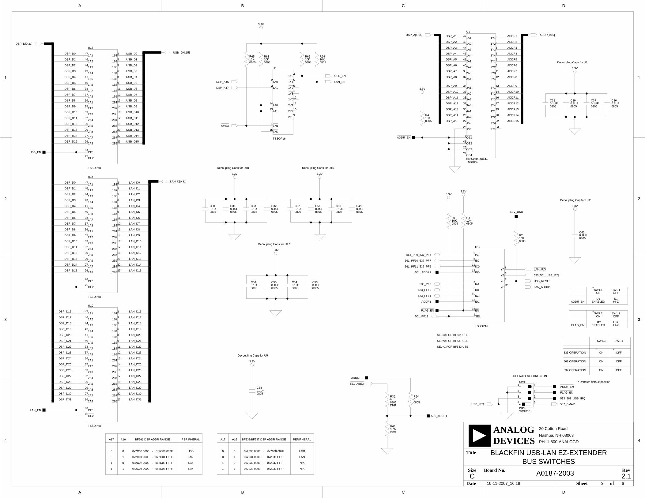
BUS SWITCHES
561_PF10_537_PF7
533_PF10
533_PF9
533_PF11
561_PF9_537_PF5
561_PF11_537_PF6LAN_IRQ
LAN_EN
AMS3
C40
08050.1UF
561_ABE3
USB_IRQ
USB_RESET
3.3V_USB
561_PF12
R62
080510K46
44
43
41
40
38
37
2
3
5
6
8
9
11
12
36
35
33
32
30
29
27
13
14
16
17
19
20
22
23
47
26
48
25
U17
TSSOP48
USB_D[0:15]USB_D0
USB_D1
USB_D2
USB_D3
USB_D4
USB_D5
USB_D6
USB_D8
USB_D9
USB_D10
USB_D11
USB_D12
USB_D13
USB_D14
USB_D15
USB_D7
DSP_D15
DSP_D14
DSP_D13
DSP_D12
DSP_D11
DSP_D10
DSP_D9
DSP_D8
DSP_D7
DSP_D6
DSP_D5
DSP_D4
DSP_D3
DSP_D2
DSP_D1
DSP_D0
DSP_D16
DSP_D17
DSP_D18
DSP_D19
DSP_D20
DSP_D21
DSP_D22
DSP_D23
DSP_D24
DSP_D25
DSP_D26
DSP_D27
DSP_D28
DSP_D29
DSP_D30
DSP_D31
DSP_D[0:31]
DSP_D1
DSP_D2
DSP_D3
DSP_D4
DSP_D5
DSP_D6
DSP_D7
DSP_D8
DSP_D9
DSP_D10
DSP_D11
DSP_D12
DSP_D13
DSP_D14
DSP_D15
DSP_D0
USB_EN
080510KR65
0.1UF0805
C52 C51
08050.1UF
C50
08050.1UF 0.1UF
0805
C49
C56
08050.1UF 0.1UF
0805
C550.1UF0805
C54 C53
08050.1UF
SHGND
2.5VAVCC
AGND
D
4
3
2
1
A B C
20 Cotton Road
Nashua, NH 03063
A B C D
4
3
2
1
PH: 1-800-ANALOGD
C
Title
Size Board No.
Date Sheet of
DEVICESANALOG
RevA0187-2003
BLACKFIN USB-LAN EZ-EXTENDER
2.1
AGND
AVCC
AVCC 2.5V
AGND
AGND
2.5V2.5V
V_SELECT
5V
GNDSD
INPUT
ERR
OUTPUT
D+
D-
GND
SHELL
VCC
GNDSD
INPUT
ERR
OUTPUT
NET2272
RREF
LA0
LA1
LA2
LA3
LA4
IOW
RESET
ALE
CS
IOR
DMARD
DMAWR
DACK
EOT
TEST
TRST
TMC2
XIN
XOUT
VBUS
LD0
LD1
LD2
LD3
LD4
LD5
LD6
LD7
LD8
LD9
LD10
LD11
LD12
LD13
LD14
LD15
LCLKO
DREQ
IRQ
RSDM
DM
DP
RSDP
RPU
USB 2.0
NET2272
AVSS2
AVSS1
GND2
GND1
VSSIO3
VSSIO2
VSSIO1
VSSC2
VDDC1
VDDC2
VDD25
AVDD
PVDD
VDDIO1
VDDIO2
VDDIO3
VDD33
VSSC1
COM
USB 2.0
Decoupling Caps for U9Decoupling Caps for U9Decoupling Caps for U9
6410-11-2007_16:18
14
12
10
4
54
41
33
56
1
48
3
15
11
27
42
55
7
24
16
U9
TQFP64
13
32
31
30
29
28
60
58
53
61
59
50
34
51
52
18
40
17
25
26
64
19
20
21
22
23
35
36
37
38
39
43
44
45
46
47
49
57
62
63
9
8
6
5
2
U9
TQFP64 1
3
2
6
4
VR2
SOT23-6ADP3330ARTZ-33
C40.47UF0805
08050.47UFC45
Y2
OSC01030MHZ
C10.01UF0805
2
3
4
5
1J3
CON009USB
4
6
2
3
1
VR1
SOT23-6ADP3330ARTZ-25
FER1
1206600
TP4
R2139.00805
R1939.00805
R201.5K0805
R61M0805
C4610PF0805
C4710PF0805
3.3V_USB
08051UFC42R46
00805
USB_VBUS
R11
080510K
FER5
080542
3.3V_USB
3.3V_USB
3.3V_USB
R52.43K0805
USB_EOT
USB_LCLK0
USB_VBUS
FER6
080542
10K0805
R1810K0805
R12
CT1
B10UF
C3
08050.01UF
C2
08050.1UF
0.47UFC5
0805
R747.0K0805
USB_IRQ
ADDR5
ADDR4
ADDR2
ADDR3
ADDR[2:6]
ADDR6
USB_DREQ
USB_ALE
USB_DMARD
AWE
ARE
USB_TCM2
USB_TCM2
USB_TRST
USB_TEST
USB_EOT
USB_DACK
USB_DMAWR
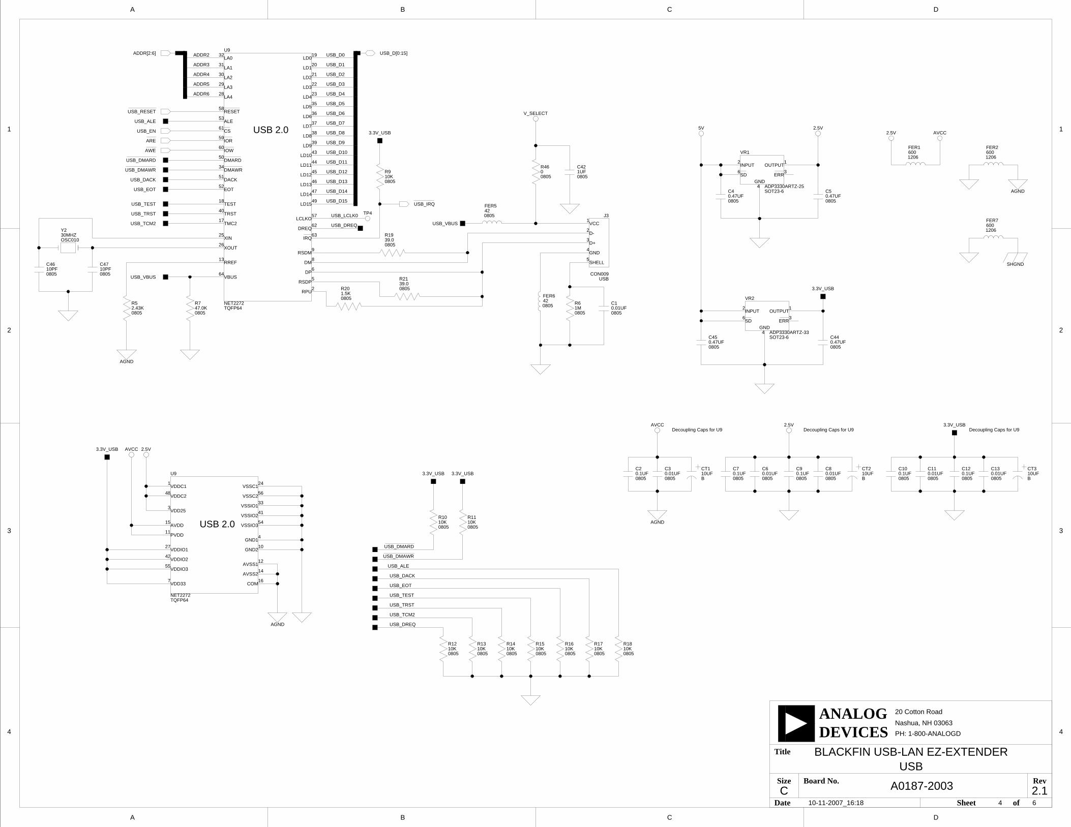
USB
USB_ALE
USB_DACK
USB_TEST
USB_TRST
USB_DREQ
USB_RESET
USB_D[0:15]
USB_D7
USB_D15
USB_D14
USB_D13
USB_D12
USB_D11
USB_D10
USB_D9
USB_D8
USB_D6
USB_D5
USB_D4
USB_D3
USB_D2
USB_D1
USB_D0
10K0805
R9
1206
FER2600
USB_DMARD
10K0805
R10
R13
080510K 10K
0805
R14 R15
080510K 10K
0805
R16 R17
080510K
0.1UF0805
C70.01UF0805
C6 C9
08050.1UF
C8
08050.01UF 10UF
B
CT2 CT3
B10UF0.01UF
0805
C130.1UF0805
C12C11
08050.01UF
C10
08050.1UF
USB_EN
0805
C440.47UF
3.3V_USB
USB_DMAWR
3.3V_USB
FER7
1206600
SHGND2
A3V
3.3V
A3V
A3V
A3V
A3V
A3V
D
4
3
2
1
A B C
20 Cotton Road
Nashua, NH 03063
A B C D
4
3
2
1
PH: 1-800-ANALOGD
C
Title
Size Board No.
Date Sheet of
DEVICESANALOG
RevA0187-2003
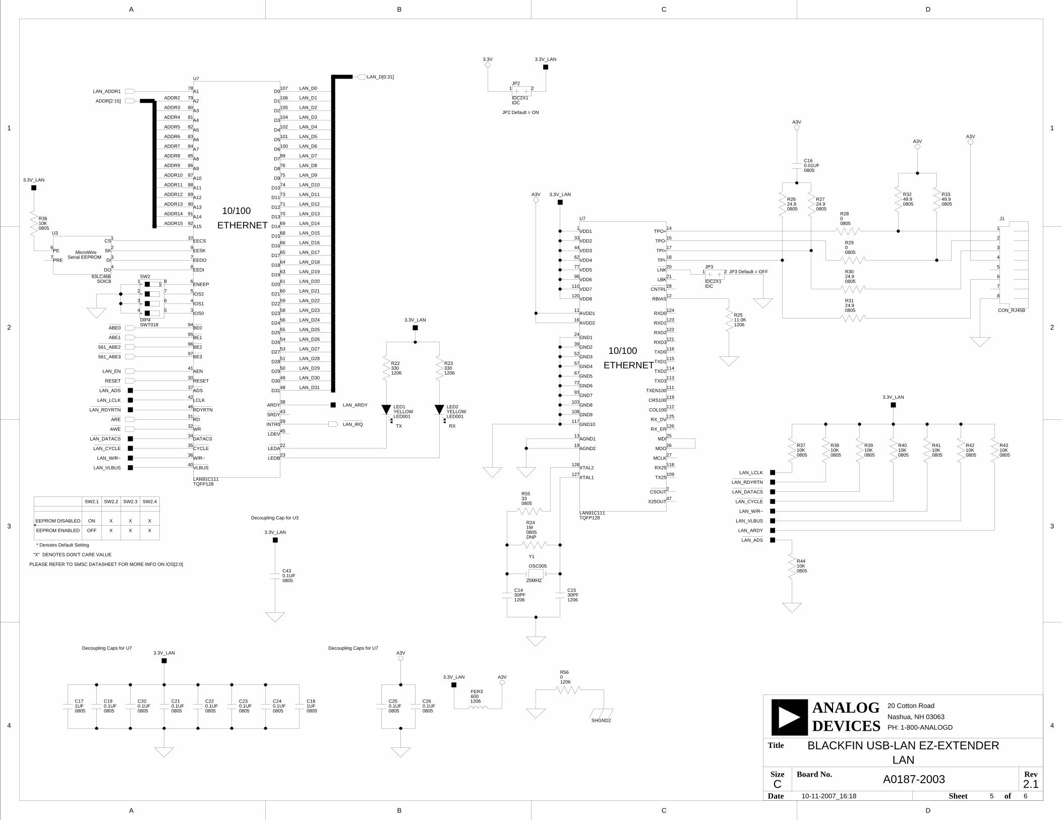
BLACKFIN USB-LAN EZ-EXTENDER
2.1
SK
CS
PRE
PE
DI
DO
MicroWireSerial EEPROM
ON1
23
4
LAN91C111
A1
A10
A11
A12
A13
A14
A15
A2
A3
A4
A5
A6
A7
A8
A9
AEN
ARDY
D0
D1
D10
D11
D12
D13
D14
D15
D16
D17
D18
D19
D2
D20
D21
D22
D23
D24
D25
D26
D27
D28
D29
D3
D30
D31
D4
D5
D6
D7
D8
D9
EECS
EEDI
EEDO
EESK
ENEEP
IOS0
IOS1
IOS2
LCLK
RESET
W/R~
ADS
BE0
BE1
BE2
BE3
CYCLE
DATACS
INTR0
LDEV
LEDA
LEDB
RD
RDYRTNSRDY
VLBUS
WR
10/100
ETHERNET
LAN91C111
AGND1
AGND2
AVDD1
AVDD2
COL100
CRS100
GND1
GND10
GND2
GND3
GND4
GND5
GND6
GND7
GND8
GND9
LBK
MCLK
MDI
MDO
RBIAS
RX25
RXD0
RXD1
RXD2
RXD3
RX_DV
RX_ER
TPI+
TPI-
TPO+
TPO-
TX25
TXD0
TXD1
TXD2
TXD3
TXEN100
VDD1
VDD2
VDD3
VDD4
VDD5
VDD6
VDD7
VDD8
X25OUT
XTAL1
XTAL2
CNTRL
CSOUT
LNK
10/100
ETHERNET
XXX
RXTX
Decoupling Caps for U7Decoupling Caps for U7
Decoupling Cap for U3
JP3 Default = OFF
SW2.3 SW2.4SW2.2
OFFEEPROM ENABLED
SW2.1
ON X X XEEPROM DISABLED
PLEASE REFER TO SMSC DATASHEET FOR MORE INFO ON IOS[2:0]
* Denotes Default Setting
"X" DENOTES DON'T CARE VALUE
*
JP2 Default = ON
10-11-2007_16:18 5 6
33
1
44
62
77
98
110
120
11
16
24
39
52
57
67
72
93
103
108
117
13
14
15
17
18
20
21
28
12
124
123
122
121
116
115
114
113
111
119
112
125
126
25
26
27
118
109
2
47
19
128
127
U7
TQFP128
4
3
5
6
7
8
9
10
40
46
37
32
41
94
95
97
66
49
50
51
53
54
55
58
59
60
61
64
65
92
91
90
89
88
87
86
85
84
83
82
79
80
81
106
105
104
102
101
100
99
76
75
74
73
71
69
107
68
42
36
96
63
56
43
22
23
48
78
70
31
34
35
38
30
29
45
U7
TQFP128
2
3
1
4 5
6
7
8SW2
SWT018DIP4
2
1
7
6
3
4
U3
SOIC893LC46B
10K0805
R36
R241M0805DNP
1
2
3
4
5
6
7
8
CON_RJ45B
J1
1 2JP2
IDC2X1IDC
1 2JP3
IDC2X1IDC
LAN
C1430PF1206
Y1
OSC005
25MHZ
ABE0
LAN_D15
LAN_D13
LAN_D0
LAN_D1
LAN_D2
LAN_D3
LAN_D4
LAN_D5
LAN_D6
LAN_D7
LAN_D8
LAN_D9
LAN_D10
LAN_D11
LAN_D12
LAN_D14
LAN_D27
LAN_D31
LAN_D30
LAN_D29
LAN_D28
LAN_D26
LAN_D25
LAN_D24
LAN_D23
LAN_D22
LAN_D21
LAN_D20
LAN_D19
LAN_D18
LAN_D17
LAN_D16
LAN_D[0:31]
R223301206
080533R55
R5601206
0.1UF0805
C43
R44
080510K
LED1
LED001YELLOW
3.3V_LAN
3.3V_LAN
3.3V_LAN
3.3V_LAN
3.3V_LAN
3.3V_LAN
3.3V_LAN
R2511.0K1206
R3349.90805
R3249.90805
R2724.90805
R2624.90805
R3024.90805
R3124.90805
ADDR3
ADDR2
ADDR15
ADDR14
ADDR13
ADDR12
ADDR11
ADDR10
ADDR9
ADDR8
ADDR7
ADDR6
ADDR5
ADDR4
ADDR[2:15]
LAN_ADDR1
561_ABE3
LAN_ARDY
C17
08051UF 1UF
0805
C18
FER3
1206600
10K0805
R4310K0805
R37
R2900805
R2800805
C160.01UF0805
C1530PF1206
R233301206
LAN_ARDY
LAN_ADS
LAN_LCLK
LAN_RDYRTN
LAN_DATACS
LAN_CYCLE
LAN_W/R~
LAN_VLBUS
LAN_IRQ
LAN_VLBUS
LAN_W/R~
LAN_CYCLE
LAN_DATACS
LAN_RDYRTN
561_ABE2
ABE1
AWE
ARE
LAN_ADS
LAN_LCLK
R38
080510K 10K
0805
R39 R40
080510K 10K
0805
R41 R42
080510K
0.1UF0805
C19 C20
08050.1UF 0.1UF
0805
C21 C22
08050.1UF 0.1UF
0805
C23 C24
08050.1UF
C25
08050.1UF 0.1UF
0805
C26
LAN_EN
RESET
3.3V_LAN
YELLOWLED001
LED2
5VV_SELECT
AGND2
5V
AGND2
AGND2AGND2
TLV431A
PA1134
AGND2
5V
COL
CRS
GND1
GND10
GND11
GND12
GND13
GND14
GND15
GND16
GND17
GND18
GND2
GND3
GND4
GND5
GND6
GND7
GND8
GND9
MDC
MDIO
RXD0
RXD1
RXD2
RXD3
RX_CLK
RX_DV
RX_ER
TXD0
TXD1
TXD2
TXD3
TX_CLK
TX_EN
TX_ER
VCC1
VCC2
VCC3
VCC4
LTC4267
VPORTP
RCLASS
PGND1
PGND2
PGND3
PGND4
SIGDISA
VPORTN
PVCC
PWRGD
NGATE
ITH/RUN
POUT
VFB
SENSE
NC
D
4
3
2
1
A B C
20 Cotton Road
Nashua, NH 03063
A B C D
4
3
2
1
PH: 1-800-ANALOGD
C
Title
Size Board No.
Date Sheet of
DEVICESANALOG
RevA0187-2003
BLACKFIN USB-LAN EZ-EXTENDER
2.1
+
-~B
~A
SOURCE OF 5V PWR
EZ-KIT POWER NO JUMPER*
JP1 and JP2
JP2 and JP3ADSP-BF537 EZ-KIT LITE ONLY
*DENOTES DEFAULT SETTING
WARNING: THE EZ-KIT LITE MUST NOT BE POWERED
WHEN THESE JUMPERS ARE POPULATED.
MII INTERFACE
FOR USE WITH ADSP-BF537 EZ-KIT LITE ONLY
POWER OVER ETHERNET CIRCUITRY
FOR USE WITH ADSP-BF537 EZ-KIT LITE ONLY
POE POWER
JP1 SETTING
USB TEST MODE
10-11-2007_16:18 6 6
SBM1040
10ADIO004
D2
1
2
40ADIO003
D1SMAJ58A1
23
4
D4
MDIP4
00805
R59
DNP
R58
08050
DNP
3
1
2
JP1
IDC3X1
POE, MII, PWR SELECTION
CT54.7UFBDNP
3
4
1 5 62
U11
TSOP6SI3440DV
4
3
1
2
U8
ICS006PS2911-1
13
5
1
8
9
16
12
7
4
11
3
2
10
15
14
6
U4
SSOP16
POE_PWR
18
19
22
31
32
33
34
35
36
37
38
39
23
24
25
26
27
28
29
30
3
2
7
6
5
4
9
8
10
14
15
16
17
12
13
11
1
20
21
40
J2
CON03640PIN
DL35
D3R496.81K0805
POE_VCC+
POE_VCC-
R57
080510K
TX_ER
TP1
R4768.10805
06030.12R50
680UFCT6
E
CT44.7UFB
65
78
3
4
2
1
T1
ICS005
1
2
3
U13
SOT23-3
080510KR48
R51100.00805
08053.32KR53
R5210.0K1206
C410.1UF0805
C350.1UF0805
CRS
COL
TXD3
TXD2
TXD1
TXD0
TX_EN
TX_CLK
RX_ER
RX_CLK
RX_DV
RXD0
RXD1
RXD2
RXD3
MDC
MDIO
0.1UF0805
C48
1206
FER4600
POE_PWR
Blackfin/SHARC USB EZ-Extender Manual I-1
I INDEX
AAMS0-3 signals, 2-3architecture, of USB EZ-Extender, 2-2asynchronous memory bank, 1-2
Bbill of materials, A-1block diagram, 2-2board schematic (USB EZ-Extender), B-1
Cconfiguration, of USB EZ-Extender, 1-1CS signal, 1-3
Eexpansion interface, viii
GGPIO1-4 signals, 2-3
IIRQ line, 1-2
Jjumpers
map of locations, 2-2JP1 (USB chip select), 2-3JP2 (USB IRQ), 2-3JP3 (USB soft reset), 2-3
Pproduct overview, viii
Rreset USB controller, 1-2
Sschematic, of USB EZ-Extender, B-1setup, of USB EZ-Extender, 1-1system architecture, 2-2
Ttechnical support, xi
UUSB
interface, viii, 1-2chip select jumper (JP1), 2-3IRQ jumper (JP2), 2-3soft reset jumper (JP3), 2-3software documentation, 1-2