Embed Size (px)
Citation preview

© ABB
Slide 12015-09-27
New safety standards for collaborative robots,ABB YuMi® dual-arm robotWorkshop IROS 2015 –Robotic co-workers – methods, challenges and industrial test cases
Björn Matthias, ABB Corporate Research, 2015-09-28

© ABB
Slide 22015-09-27
Collaborative Robots
§ Introduction
§ Standardization
§ Overview of relevant standards
§ Types of collaborative operation
§ ISO/TS 15066 – status of work
§ Risk mitigation in collaborative assembly
§ YuMi®
§ Collaborative Automation
§ Collaboration & Ergonomics
§ Assembly Processes
§ Material Flow
§ Application Examples
§ Open questions
§ Summary and outlook
Status of Standardization – Example Robot: YuMi®
F
vrel
© ABB
Slide 32015-09-27
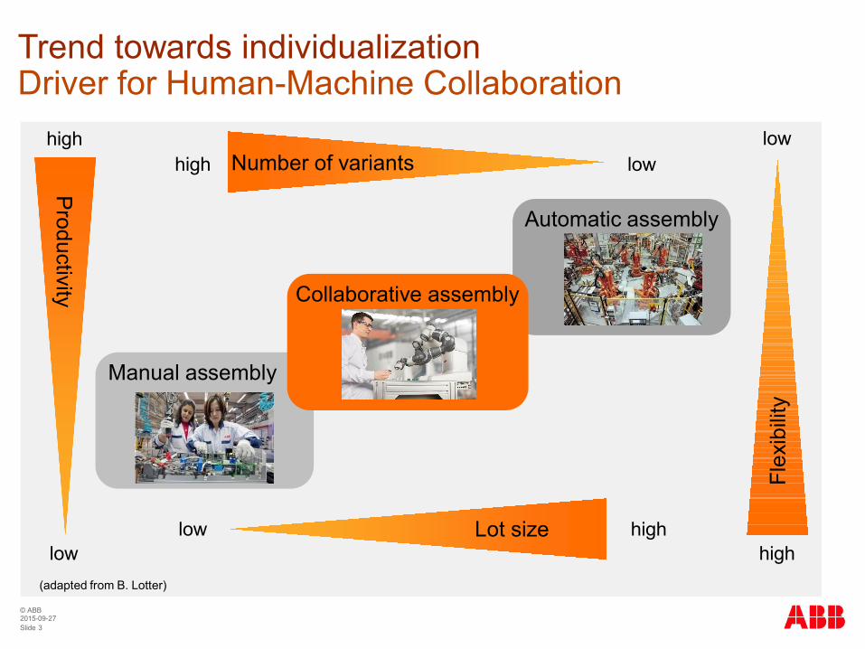
Trend towards individualizationDriver for Human-Machine Collaboration
(adapted from B. Lotter)
Number of variants lowhigh
Lot size highlow
Flex
ibilit
y
low
high
Productivity
low
high
Automatic assembly
Manual assembly
Collaborative assembly
© ABB
Slide 42015-09-27
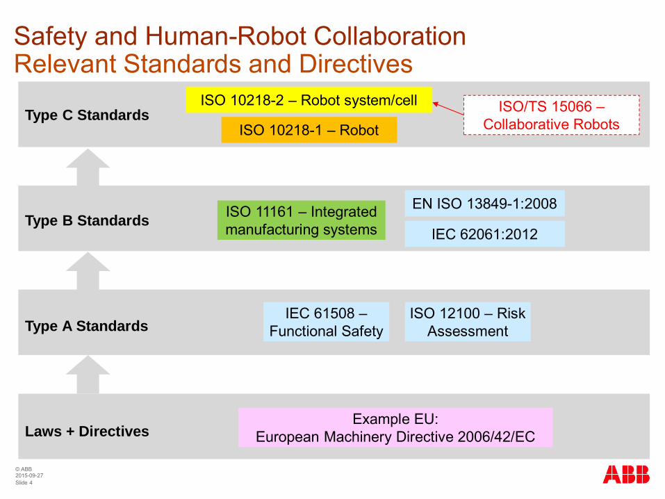
Safety and Human-Robot CollaborationRelevant Standards and Directives
Example EU:European Machinery Directive 2006/42/ECLaws + Directives
Type A Standards
Type B Standards
Type C Standards
IEC 61508 –Functional Safety
ISO 12100 – RiskAssessment
EN ISO 13849-1:2008
IEC 62061:2012
ISO 10218-1 – Robot
ISO 10218-2 – Robot system/cell
ISO 11161 – Integratedmanufacturing systems
ISO/TS 15066 –Collaborative Robots

© ABB
Slide 52015-09-27
Types of Collaborative OperationAccording to ISO 10218, ISO/TS 15066
ISO10218-1,clause
Type of collaborative operation Main means of riskreduction
5.10.2 Safety-rated monitored stop(Example: manual loading-station)
No robot motion whenoperator is in collaborativework space
5.10.3 Hand guiding(Example: operation as assist device)
Robot motion only throughdirect input of operator
5.10.4Speed and separation monitoring(Example: replenishing partscontainers)
Robot motion only whenseparation distance aboveminimum separationdistance
5.10.5
Power and force limiting by inherentdesign or control(Example: ABB YuMi® collaborativeassembly robot)
In contact events, robot canonly impart limited static anddynamics forces
© ABB
Slide 62015-09-27
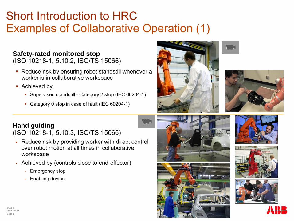
Short Introduction to HRCExamples of Collaborative Operation (1)
Safety-rated monitored stop(ISO 10218-1, 5.10.2, ISO/TS 15066)§ Reduce risk by ensuring robot standstill whenever a
worker is in collaborative workspace§ Achieved by§ Supervised standstill - Category 2 stop (IEC 60204-1)
§ Category 0 stop in case of fault (IEC 60204-1)
Hand guiding(ISO 10218-1, 5.10.3, ISO/TS 15066)§ Reduce risk by providing worker with direct control
over robot motion at all times in collaborativeworkspace
§ Achieved by (controls close to end-effector)§ Emergency stop§ Enabling device

© ABB
Slide 72015-09-27
Short Introduction to HRCExamples of Collaborative Operation (2)
Speed and separation monitoring(ISO 10218-1, 5.10.4, ISO/TS 15066)§ Reduce risk by maintaining sufficient distance between
worker and robot in collaborative workspace§ Achieved by
§ distance supervision, speed supervision§ protective stop if minimum separation distance or speed limit is
violated§ taking account of the braking distance in minimum separation
distance
§ Additional requirements on safety-rated periphery§ for example, safety-rated camera systems
Power and force limiting by inherent design orcontrol(ISO 10218-1, 5.10.5, ISO/TS 15066)§ Reduce risk by limiting mechanical loading of human-
body parts by moving parts of robot, end-effector orwork piece
§ Achieved by low inertia, suitable geometry andmaterial, sensory input, control functions, …
§ Applications involving transient and/or quasi-staticphysical contact
Speed supervision
Distance supervision
DC523 KNX Coll. HMI 2011. VR1. VR2. BJE.

© ABB
Slide 82015-09-27
ISO/TS 15066 – Present Status
§ Motivation and Purpose§ End users waiting for standards document before willing to implement applications§ Complex nature of protection schemes for collaborative applications§ Meet the developing interest in collaborative robots with specific guidance
§ Objective§ Generate a TS (technical specification) document, valid for 3 years§ After 3 years, review options
§ Confirm for 3 more years (if still deemed unsuitable for a standard)§ Integrated into ISO 10218-2 (this is the preferred outcome)§ Discard (if it turns out to be without practical relevance)
§ Responsible international working group§ ISO / TC184 (Automation systems) / SC2 (Robots and robotic devices) / WG3 (Industrial safety)§ Convenor: Pat Davison, Robotic Industries Association (USA)
§ Remaining work before first publication§ Review and process remaining technical and editorial comments from WG3 members
ISO Project Overview
© ABB
Slide 92015-09-27
ISO/TS 15066 – Present Status
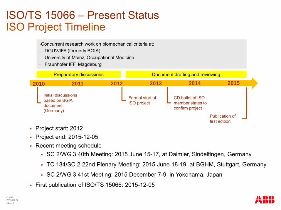
§ Project start: 2012§ Project end: 2015-12-05§ Recent meeting schedule
§ SC 2/WG 3 40th Meeting: 2015 June 15-17, at Daimler, Sindelfingen, Germany
§ TC 184/SC 2 22nd Plenary Meeting: 2015 June 18-19, at BGHM, Stuttgart, Germany
§ SC 2/WG 3 41st Meeting: 2015 December 7-9, in Yokohama, Japan
§ First publication of ISO/TS 15066: 2015-12-05
ISO Project Timeline
2010 2011 2012 2013 2014 2015
Initial discussionsbased on BGIAdocument(Germany)
Formal start ofISO project
Publication offirst edition
CD ballot of ISOmember states toconfirm project
Preparatory discussions Document drafting and reviewing
§Concurrent research work on biomechanical criteria at:• DGUV/IFA (formerly BGIA)• University of Mainz, Occupational Medicine• Fraunhofer IFF, Magdeburg
© ABB
Slide 102015-09-27
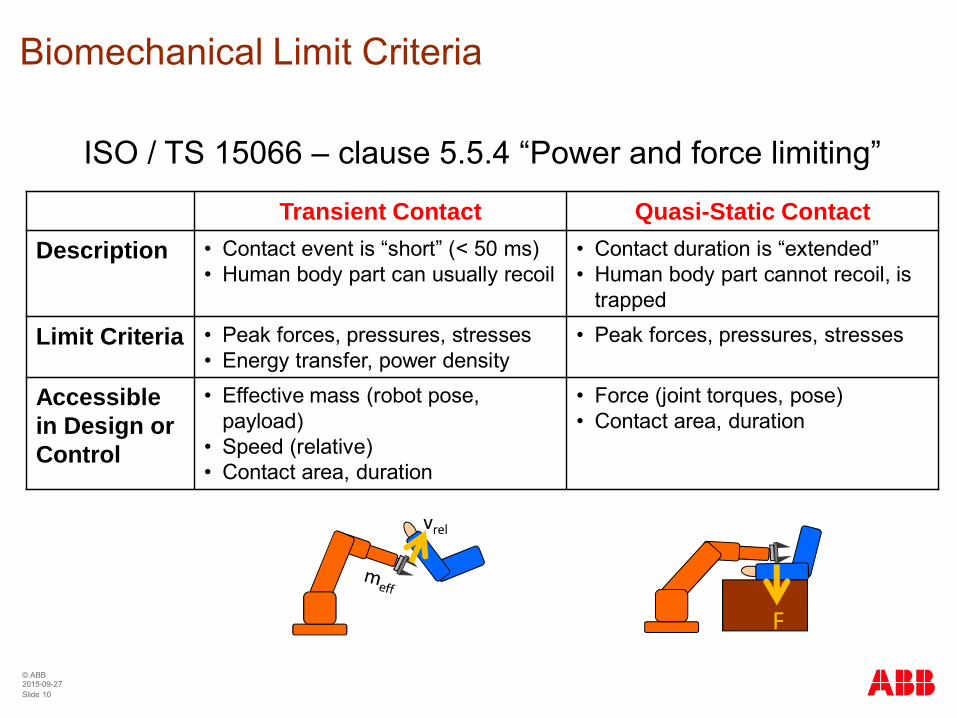
Biomechanical Limit Criteria
vrel
F
Transient Contact Quasi-Static ContactDescription • Contact event is “short” (< 50 ms)
• Human body part can usually recoil• Contact duration is “extended”• Human body part cannot recoil, is
trapped
Limit Criteria • Peak forces, pressures, stresses• Energy transfer, power density
• Peak forces, pressures, stresses
Accessiblein Design orControl
• Effective mass (robot pose,payload)
• Speed (relative)• Contact area, duration
• Force (joint torques, pose)• Contact area, duration
ISO / TS 15066 – clause 5.5.4 “Power and force limiting”
© ABB
Slide 112015-09-27
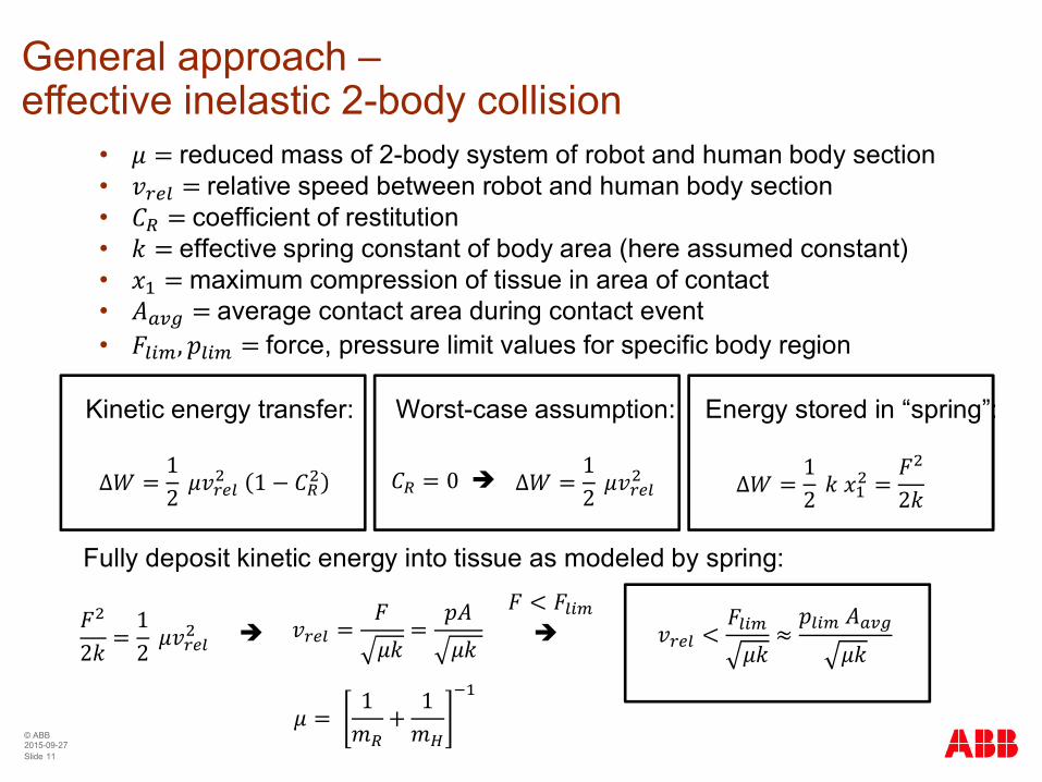
General approach –effective inelastic 2-body collision
Kinetic energy transfer:
∆ =12 1 −
Fully deposit kinetic energy into tissue as modeled by spring:
2=
12
• =reduced mass of 2-body system of robot and human body section• =relative speed between robot and human body section• =coefficient of restitution• =effective spring constant of body area (here assumed constant)• =maximum compression of tissue in area of contact• =average contact area during contact event• , =force, pressure limit values for specific body region
Worst-case assumption:
= 0 ∆ =12è
è = =
Energy stored in “spring”:
∆ =12 =
2
è<
< ≈
= 1
+1

© ABB
Slide 122015-09-27
Effective mass of robot (1)Proper formulation from complete equation of motion ofrobot
+ , + = +
Equation of motion for stiff robot
∈ ℝ : vector of joint angles
∈ ℝ × : mass/inertia matrix
∈ ℝ × : centripetal and Coriolis matrix
∈ ℝ : gravity vector
∈ ℝ : joint motor torque vector
∈ ℝ : external contact torque vector
=12
Kinetic energy
Jacobian matrixsuch that
=
Translational androtational parts
= =
=
Effective mass in direction of unit vector :
where
© ABB
Slide 132015-09-27
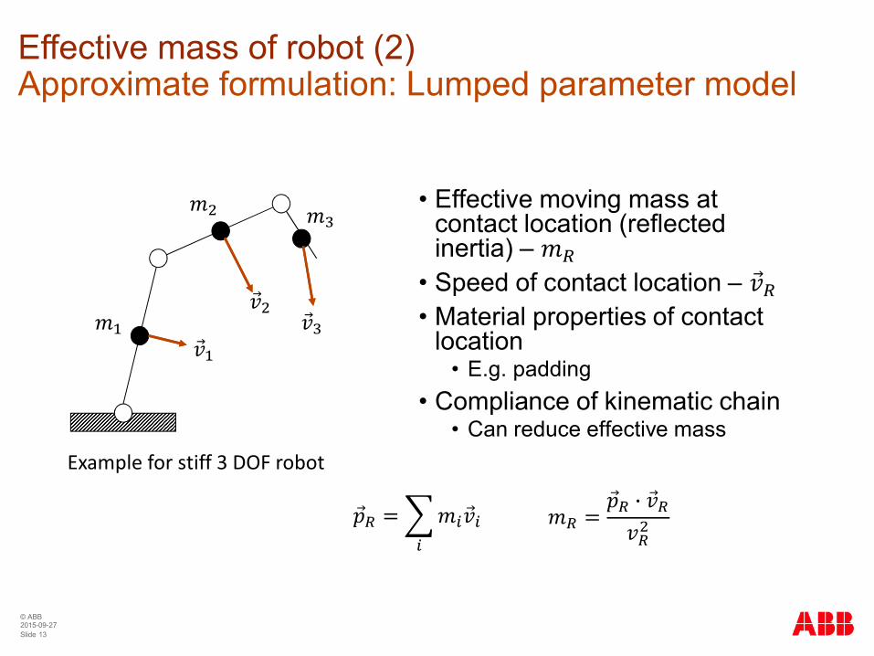
Effective mass of robot (2)Approximate formulation: Lumped parameter model
• Effective moving mass atcontact location (reflectedinertia) –
• Speed of contact location – • Material properties of contact
location• E.g. padding
• Compliance of kinematic chain• Can reduce effective mass
Example for stiff 3 DOF robot
= =
© ABB
Slide 142015-09-27
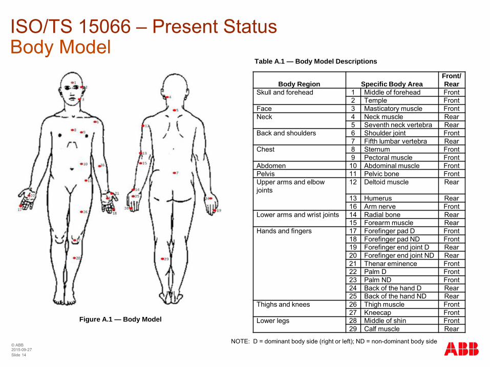
ISO/TS 15066 – Present StatusBody Model
Body Region Specific Body AreaFront/Rear
Skull and forehead 1 Middle of forehead Front2 Temple Front
Face 3 Masticatory muscle FrontNeck 4 Neck muscle Rear
5 Seventh neck vertebra RearBack and shoulders 6 Shoulder joint Front
7 Fifth lumbar vertebra RearChest 8 Sternum Front
9 Pectoral muscle FrontAbdomen 10 Abdominal muscle FrontPelvis 11 Pelvic bone FrontUpper arms and elbowjoints
12 Deltoid muscle Rear
13 Humerus Rear16 Arm nerve Front
Lower arms and wrist joints 14 Radial bone Rear15 Forearm muscle Rear
Hands and fingers 17 Forefinger pad D Front18 Forefinger pad ND Front19 Forefinger end joint D Rear20 Forefinger end joint ND Rear21 Thenar eminence Front22 Palm D Front23 Palm ND Front24 Back of the hand D Rear25 Back of the hand ND Rear
Thighs and knees 26 Thigh muscle Front27 Kneecap Front
Lower legs 28 Middle of shin Front29 Calf muscle Rear
Table A.1 — Body Model Descriptions
NOTE: D = dominant body side (right or left); ND = non-dominant body side
Figure A.1 — Body Model

© ABB
Slide 152015-09-27
YuMi® - IRB 14000 0.5/0.55Overview IRB 14000 – 0.5/0.55
Payload 0.5 kg per arm
Reach 559 mm
Repeatability 0.02 mm
Footprint 399 mm x 497 mm
Weight 38 kg
Controller IRC5 integrated in torso
Programming Lead-through or RAPID
Gripper Servo, 2x suction, integratedvision
Application supplies Ethernet, 24 V, air to flanges
Connections Ethernet, digital I/O 8in/8out, air
Temperature 5 °C – 40 °C
IP Protection IP 30
ESD Protection Certified
Clean room / food grade No
Speed Supervision Configurable up to 1.5 m/s
Safety Performance PL b, cat. B (ISO 13849-1)

© ABB
Slide 162015-09-27
Level 1
Level 2
Level 3
Level 4
Robot system – mechanical hazards
Low payload andlow robot inertia
Injury-avoiding mechanicaldesign and soft padding
Power and speedlimitation
Software-based collision detection,manual back-drivability
Level 5 Personal protectiveequipment
AB
Bco
llabo
rativ
ein
dust
rialr
obot
conc
ept
Mea
sure
sfo
rris
kre
duct
ion
and
ergo
nom
ics
impr
ovem
ent
Level 6 Perception-based real-timeadjustment to environment
Oth
er,a
pplic
atio
n-sp
ecifi
c
Qua
si-s
tatic
cont
act
Tran
sien
tcon
tact
ABB YuMi® Safety ConceptProtection Levels
© ABB
Slide 172015-09-27
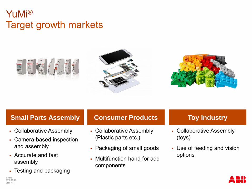
§ Collaborative Assembly(Plastic parts etc.)
§ Packaging of small goods
§ Multifunction hand for addcomponents
Small Parts Assembly Consumer Products Toy Industry
§ Collaborative Assembly§ Camera-based inspection
and assembly§ Accurate and fast
assembly§ Testing and packaging
§ Collaborative Assembly(toys)
§ Use of feeding and visionoptions
YuMi®Target growth markets
© ABB
Slide 182015-09-27
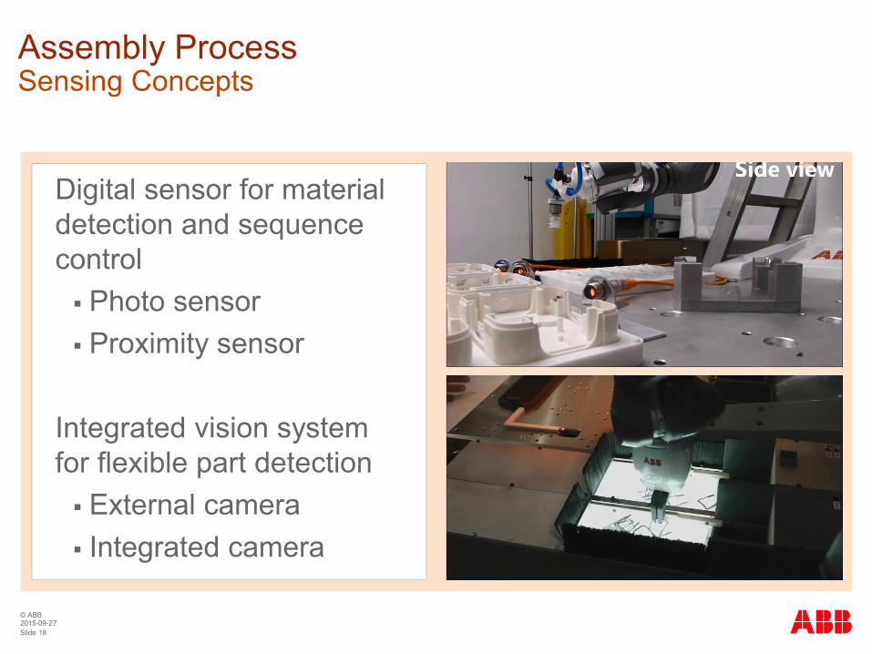
Assembly ProcessSensing Concepts
Digital sensor for materialdetection and sequencecontrol§ Photo sensor§ Proximity sensor
Integrated vision systemfor flexible part detection§ External camera§ Integrated camera
© ABB
Slide 192015-09-27
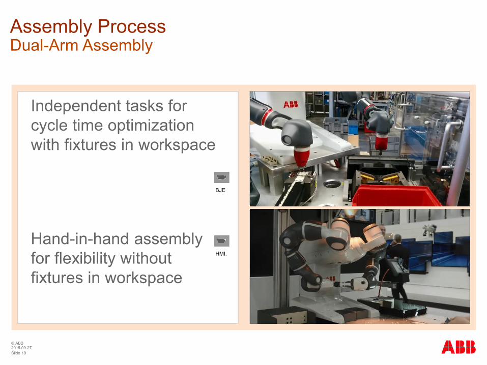
Assembly ProcessDual-Arm Assembly
Independent tasks forcycle time optimizationwith fixtures in workspace
Hand-in-hand assemblyfor flexibility withoutfixtures in workspace
HMI.
BJE
© ABB
Slide 202015-09-27
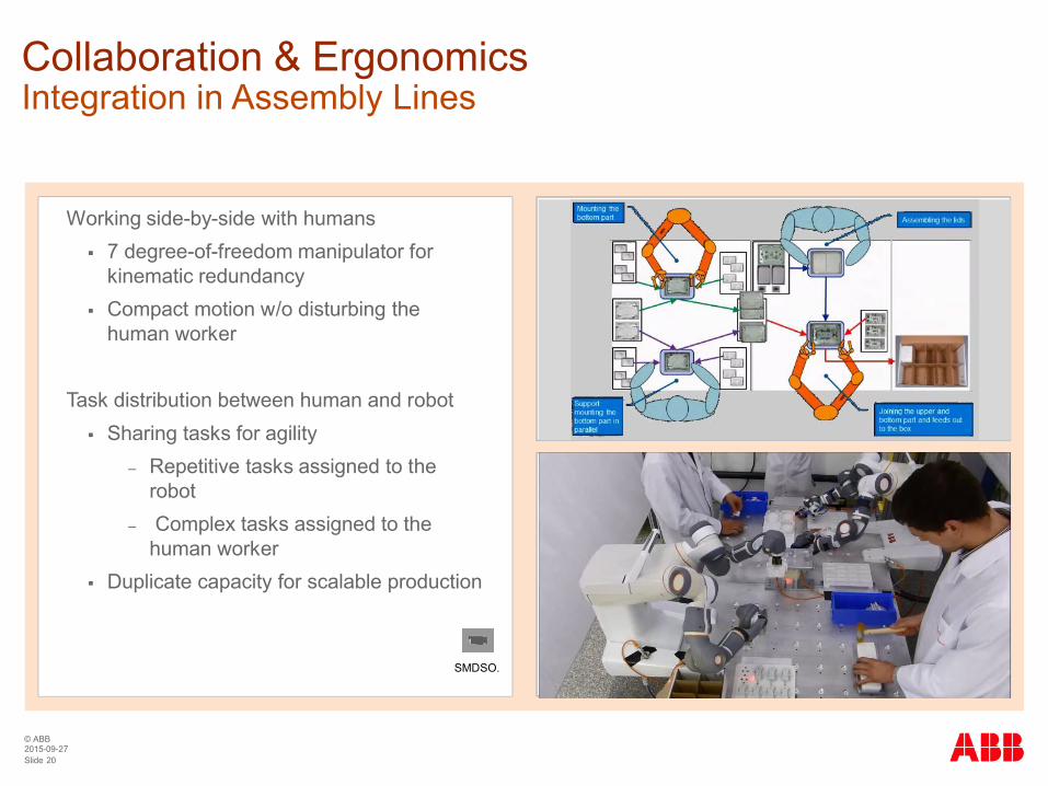
Collaboration & ErgonomicsIntegration in Assembly Lines
Working side-by-side with humans§ 7 degree-of-freedom manipulator for
kinematic redundancy§ Compact motion w/o disturbing the
human worker
Task distribution between human and robot§ Sharing tasks for agility
‒ Repetitive tasks assigned to therobot
‒ Complex tasks assigned to thehuman worker
§ Duplicate capacity for scalable production
SMDSO.

© ABB
Slide 212015-09-27
Status of Standardization – Example Robot: YuMi®
§ Safety
§ Safety-rated sensors for tracking humans in speed-and-separation-monitoring
§ More data on biomechanical limit criteria for human body regions
§ Design rules for safety-related mechanical design of collaborative manipulators
§ Dynamic adaptation of safety-configuration to momentary requirements
§ Acceptance
§ Dynamic adaptation of robot behavior to collaborative situation
§ Definition and quantification of ergonomics for collaborative situations
§ Operator controls for collaborative operation
§ Possibility of programming complex assembly tasks without expert knowledge
§ Productivity
§ Application concepts for productive collaborative assembly
§ Optimal distribution of tasks to robot or human in mixed environment
§ Economical combinations of lot sizes, variants, application complexity, …
§ Practical experience with business models
Open Questions

© ABB
Slide 222015-09-27
Status of Standardization – Example Robot: YuMi®
§ Safety standardization
§ ISO/TS 15066 publication in Dec. 2015
§ Requirements on collaborating robots incl. biomechanical criteria for power-and-force-limiting
§ Eventual integration into ISO 10218-2 is planned
§ YuMi® - IRB 14000 0.5/0.55
§ Collaborative robot according to power-and-force-limiting
§ Assembly of small lot-size / high-variant orders
§ Humans and robots combine their respective strengths
§ Outlook
§ Interdisciplinary research
§ Technological improvements and progress
§ Proving in practice
§ Revisions of standards
Summary and Outlook

© ABB
Slide 232015-09-27