Embed Size (px)
Citation preview
BitStormTM 6200 CPE User’s Guide
Document Number 6210-A2-GB20-00
November 2003
BitStorm 6200 Router User’s Guide
2
Copyright © 2003 Paradyne Corporation. All rights reserved. Printed in U.S.A.
Notice
This publication is protected by federal copyright law. No part of this publication may be copied or distributed, transmitted, transcribed, stored in a retrieval system, or translated into any human or computer language in any form or by any means, electronic, mechanical, magnetic, manual or otherwise, or disclosed to third parties without the express written permission of Paradyne Corporation, 8545 126th Ave. N., Largo, FL 33773.
Paradyne Corporation makes no representation or warranties with respect to the contents hereof and specifically disclaims any implied warranties of merchantability or fitness for a particular purpose. Further, Paradyne Corporation reserves the right to revise this publication and to make changes from time to time in the contents hereof without obligation of Paradyne Corporation to notify any person of such revision or changes.
Changes and enhancements to the product and to the information herein will be documented and issued as a new release to this manual.
Warranty, Sales, Service, and Training Information
Contact your local sales representative, service representative, or distributor directly for any help needed. For additional information concerning warranty, sales, service, repair, installation, documentation, training, distributor locations, or Paradyne worldwide office locations, use one of the following methods:
Internet: Visit the Paradyne World Wide Web site at www.paradyne.com. (Be sure to register your warranty at www.paradyne.com/warranty.)
Telephone: Call our automated system to receive current information by fax or to speak with a company representative.
Within the U.S.A., call 1-800-870-2221
Outside the U.S.A., call 1-727-530-2340
Document Feedback
We welcome your comments and suggestions about this document. Please mail them to Technical Publications, Paradyne Corporation, 8545 126th Ave. N., Largo, FL 33773, or send e-mail to [email protected]. Include the number and title of this document in your correspondence. Please include your name and phone number if you are willing to provide additional clarification.
Trademarks
Acculink, Comsphere, ETC, Etherloop, FrameSaver, GranDSLAM, Hotwire, the Hotwire logo, Jetstream, MVL, NextEDGE, OpenLane, Paradyne, the Paradyne logo, Paradyne Credit Corp., the Paradyne Credit Corp. logo, Performance Wizard, StormPort, TruPut are all registered trademarks of Paradyne Corporation. ADSL/R, BitStorm, Connect to Success, GrandVIEW, Hotwire Connected, iMarc, JetFusion, JetVision, MicroBurst, PacketSurfer, ReachDSL, Spectrum Manager, StormTracker and TriplePlay are trademarks of Paradyne Corporation. All other products and services mentioned herein are the trademarks, service marks, registered trademarks, or registered service marks of their respective owners.
BitStorm 6200 Router User’s Guide
3
Important Safety Instructions
1. Read and follow all warning notices and instructions marked on the product or included in the manual.
2. Slots and openings in the cabinet are provided for ventilation. To ensure reliable operation of the product and to protect it from overheating, these slots and openings must not be blocked or covered.
3. Do not allow anything to rest on the power cord and do not locate the product where persons will walk on the power cord.
4. Do not attempt to service this product yourself, as opening or removing covers may expose you to dangerous high voltage points or other risks. Refer all servicing to qualified service personnel.
5. General purpose cables are used with this product for connection to the network. Special cables, which may be required by the regulatory inspection authority for the installation site, are the responsibility of the customer. Use a UL Listed, CSA certified, minimum No. 24 AWG line cord for connection to the Digital Subscriber Line (DSL) network.
6. When installed in the final configuration, the product must comply with the applicable Safety Standards and regulatory requirements of the country in which it is installed. If necessary, consult with the appropriate regulatory agencies and inspection authorities to ensure compliance.
7. A rare phenomenon can create a voltage potential between the earth grounds of two or more buildings. If products installed in separate buildings are interconnected, the voltage potential may cause a hazardous condition. Consult a qualified electrical consultant to determine whether or not this phenomenon exists and, if necessary, implement corrective action prior to interconnecting the products.
8. Input power to this product must be provided by one of the following: (1) a UL Listed/CSA certified power source with a Class 2 or Limited Power Source (LPS) output for use in North America, or (2) a certified transformer, with a Safety Extra Low Voltage (SELV) output having a maximum of 240 VA available, for use in the country of installation.
9. In addition, since the equipment is to be used with telecommunications circuits, take the following precautions:
— Never install telephone wiring during a lightning storm.
— Never install telephone jacks in wet locations unless the jack is specifically designed for wet locations.
— Never touch uninsulated telephone wires or terminals unless the telephone line has been disconnected at the network interface.
— Use caution when installing or modifying telephone lines.
— Avoid using a telephone (other than a cordless type) during an electrical storm. There may be a remote risk of electric shock from lightning.
— Do not use the telephone to report a gas leak in the vicinity of the leak.
CE Marking When the product is marked with the CE mark on the equipment label, a supporting Declaration of Conformity may be downloaded from the Paradyne World Wide Web site at www.paradyne.com. Select Support -> Technical Manuals -> CE Declarations of Conformity.

BitStorm 6200 Router User’s Guide
4
FCC Declaration
An FCC Declaration of Conformity may be downloaded from the Paradyne World Wide Web site at www.paradyne.com. Select Support -> Technical Manuals -> Declarations of Conformity.
Notice to Users of the United States Telephone Network This equipment complies with Part 68 of the FCC rules and the requirements adopted by the Administrative Council for Terminal Attachment (ACTA). On the bottom side of this equipment is a label that contains, among other information, a product identifier in the format US:AAAEQ##TXXXX. If requested, this number must be provided to the Telephone Company.
This equipment is intended to connect to the Public Switched Telephone Network through a Universal Service Order Code (USOC) type RJ11C jack. A plug and jack used to connect this equipment to the premises wiring and telephone network must comply with the applicable FCC Part 68 rules and requirements adopted by the ACTA. A compliant telephone cord and modular plug is provided with this product. It has been designed to be connected to a compatible modular jack that is also compliant.
The Ringer Equivalence Number (or REN) is used to determine the number of devices that may be connected to a telephone line. Excessive RENs on a telephone line may result in the devices not ringing in response to an incoming call. In most but not all areas, the sum of RENs should not exceed five (5.0). To be certain of the number of devices that may be connected to a line, as determined by the total RENs, contact the local Telephone Company. The REN for this product is part of the product identifier that has the format US:AAAEQ##TXXXX. The digits represented by ## are the REN without a decimal point. For example, 03 represents a REN of 0.3.
If the ADSL modem causes harm to the telephone network, the Telephone Company will notify you in advance that temporary discontinuance of service may be required. But if advance notice is not practical, the Telephone Company will notify the customer as soon as possible. Also, you will be advised of your right to file a complaint with the FCC if you believe it is necessary.
The Telephone Company may make changes in its facilities, equipment, operations or procedures that could affect the operation of the equipment. If this happens, the Telephone Company will provide advance notice in order for you to make necessary modifications to maintain uninterrupted service. If trouble is experienced with the ADSL modem, refer to the repair and warranty information in this document.
If the equipment is causing harm to the telephone network, the Telephone Company may request that you disconnect the equipment until the problem is resolved.
The user may make no repairs to the equipment.
Connection to party line service is subject to state tariffs. Contact the state public utility commission, public service commission or corporation commission for information.
If the site has specially wired alarm equipment connected to the telephone line, ensure the installation of the ADSL modem does not disable the alarm equipment. If you have questions about what will disable alarm equipment, consult your Telephone Company or a qualified installer.
Notice to Users of the Canadian Telephone Network
NOTICE: This equipment meets the applicable Industry Canada Terminal Equipment Technical Specifications. This is confirmed by the registration number. The abbreviation IC before the registration number signifies that registration was performed based on a Declaration of Conformity indicating that Industry Canada technical specifications were met. It does not imply that Industry Canada approved the equipment.
NOTICE: The Ringer Equivalence Number (REN) for this terminal equipment is labeled on the equipment. The REN assigned to each terminal equipment provides an indication of the maximum number of terminals allowed to be connected to a telephone interface. The termination on an interface may consist of any combination of devices subject only to the requirement that the sum of the Ringer Equivalence Numbers of all the devices does not exceed five.
If your equipment is in need of repair, contact your local sales representative, service representative, or distributor directly.

BitStorm 6200 Router User’s Guide
5
CANADA – EMI NOTICE: This Class B digital apparatus meets all requirements of the Canadian interference-causing equipment regulations.
Cet appareil numérique de la classe B respecte toutes les exigences du règlement sur le matérial brouilleur du Canada.
BitStorm 6200 Router User’s Guide
6
Table of Contents
1 Introduction .............................................9
1.1 Models.................................................................................................................. 9 1.2 Features ............................................................................................................... 9 1.3 System Requirements.......................................................................................... 9 1.4 Using this Document .......................................................................................... 10
1.4.1 Notational conventions........................................................ 10 1.4.2 Typographical conventions ................................................. 10 1.4.3 Special messages............................................................... 10
1.5 Getting Support .................................................................................................. 10
2 Getting to Know the BitStorm 6200 CPE.......................................................11
2.1 Parts List............................................................................................................. 11 2.2 Front Panel......................................................................................................... 12 2.3 Rear Panel ......................................................................................................... 13
3 Getting Started......................................14
3.1 Connecting the Hardware .................................................................................. 14 3.1.1 Connect the ADSL line........................................................ 14 3.1.2 Connect the computers or a LAN ....................................... 14 3.1.3 Attach the power adapter.................................................... 14 3.1.4 Turn on your computer..........Error! Bookmark not defined.
3.2 Configuring Your PC .......................................................................................... 16 3.2.1 Windows XP:....................................................................... 16 3.2.2 Windows 2000: ................................................................... 17 3.2.3 Windows Me: ...................................................................... 18 3.2.4 Windows 95, 98: ................................................................. 18 3.2.5 Windows NT 4.0:................................................................. 19 3.2.6 Assigning IP to your PC automatically by DHCP................ 20
3.3 Login to your CPE .............................................................................................. 20
4 Device Information................................22
4.1 Summary............................................................................................................ 22 4.2 WAN................................................................................................................... 22
BitStorm 6200 Router User’s Guide
7
4.3 Statistics ............................................................................................................. 23 4.3.1 LAN Statistics...................................................................... 23 4.3.2 ATM Statistics ..................................................................... 23 4.3.3 ADSL Statistics ................................................................... 24
4.4 Route.................................................................................................................. 24 4.5 ARP.................................................................................................................... 25
5 Management.........................................26
5.1 Update Software................................................................................................. 26 5.2 Restore Settings................................................................................................. 26 5.3 User Access ....................................................................................................... 27 5.4 Reboot CPE ....................................................................................................... 27
6 Diagnostics ...........................................28
Index 29

BitStorm 6200 Router User’s Guide
8
BitStorm 6200 Router User’s Guide
9
1 Introduction Congratulations on becoming the owner of a BitStorm 6200 CPE (Customer Premises Equipment). Your LAN (Local Area Network) will now be able to access the Internet via the CPE’s ADSL connection.
This user’s guide shows how to set up the BitStorm 6200 CPE and how to use its web interface.
1.1 Models
The BitStorm 6200 Series CPE comes in two models:
Model 6210 – is set in the factory to run in bridge mode. It does not support router functions. Model 6211 – is set in the factory to run in router mode. It has configuration options outside the
scope of this manual. See the BitStorm 6211 CPE User’s Guide (document number 6211-A2-GB20) for more information. It is available at www.paradyne.com. Select Support -> Technical Manuals -> BitStorm DSL Systems.
Definition
A bridge is a device that forwards any message from one part of a network to another. The Model 6210 CPE is a bridge. A router is a device that forwards messages according to their network addresses. The Model 6211 CPE is a router.
1.2 Features
Built-in ADSL modem in the CPE, which offers up to 8Mbps/800Kbps Internet surf speed for Downstream/Upstream, respectively. 10/100BaseT Ethernet router to provide Internet connectivity to all computers on your LAN via
additional Ethernet Switch/HUB. NAT (Network Address Translation) and Firewall functions to provide secure Internet access for
your LAN (Model 6211 only). Configuration program accessible via Microsoft Internet Explorer. Note that Netscape is not
supported.
1.3 System Requirements
In order to use the BitStorm 6200 CPE for Internet access, you must have the following:
ADSL service subscription from your ISP. One computer containing an Ethernet 10BaseT/100BaseT network interface card (NIC). (Optional) An Ethernet hub/switch, if you are connecting the device to several computers on an
Ethernet network. For system monitoring or configuration using the supplied web-based program: a web browser
such as Internet Explorer Version 5.5 or later.
BitStorm 6200 Router User’s Guide
10
1.4 Using this Document
1.4.1 Notational conventions For brevity, the BitStorm 6200 CPE is referred to as “the CPE.” The terms LAN and network are used interchangeably to refer to a group of Ethernet-connected
computers at one site.
1.4.2 Typographical conventions Boldface type text is used for items you select from menus and drop-down lists, and text strings
you type when prompted by the program.
1.4.3 Special messages This document uses the following icons to call your attention to specific instructions or explanations.
Note
Provides clarification or non-essential information on the current topic.
Definition
Explains terms that may be unfamiliar to the reader.
WARNING
Provides messages of high importance, including messages relating to personal safety or system integrity.
1.5 Getting Support
Obtain support for your BitStorm 6200 CPE from the service provider you received the device from.
BitStorm 6200 Router User’s Guide
11
2 Getting to Know the BitStorm 6200 CPE
2.1 Parts List
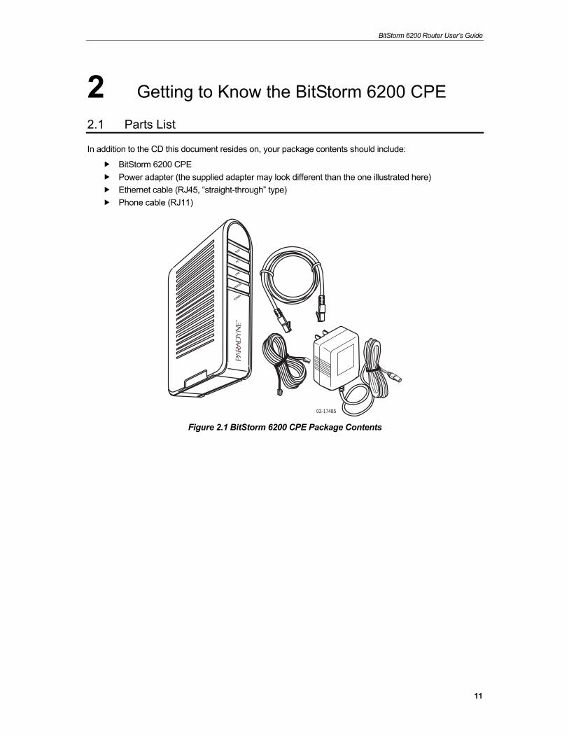
In addition to the CD this document resides on, your package contents should include:
BitStorm 6200 CPE Power adapter (the supplied adapter may look different than the one illustrated here) Ethernet cable (RJ45, “straight-through” type) Phone cable (RJ11)
TEST
PC
LINE
STATUS
POWER
03-17485 Figure 2.1 BitStorm 6200 CPE Package Contents
BitStorm 6200 Router User’s Guide
12
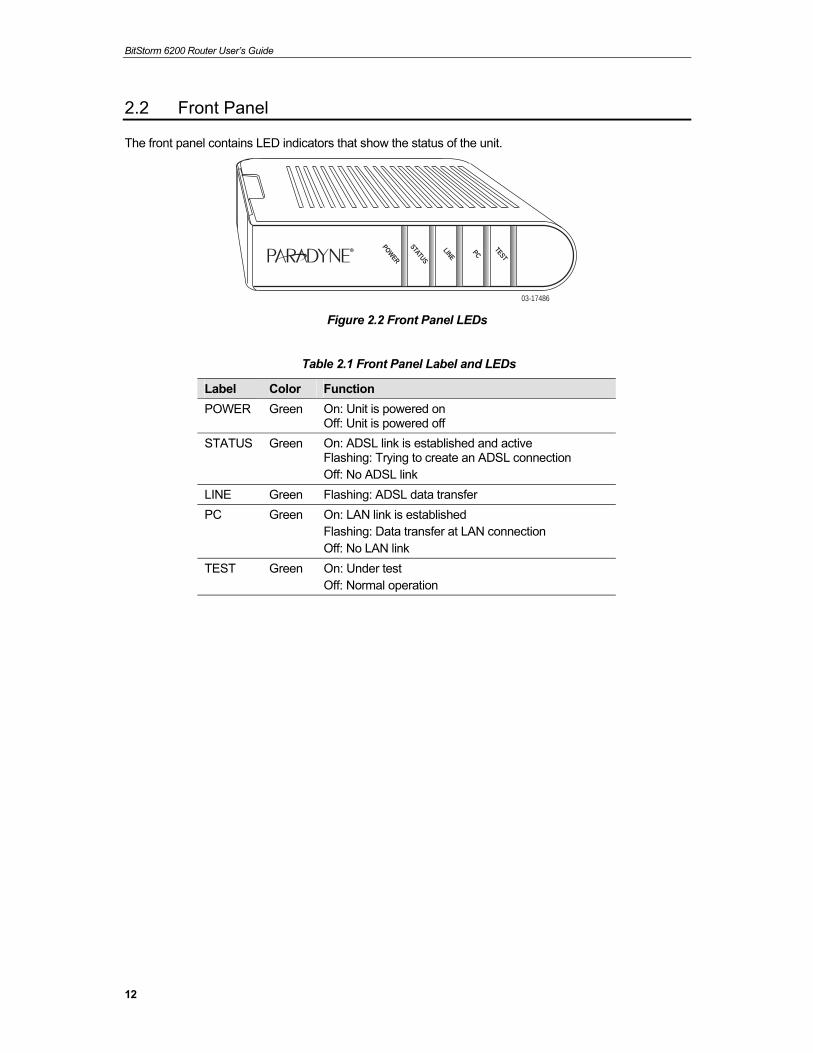
2.2 Front Panel
The front panel contains LED indicators that show the status of the unit.
03-17486
TEST
PC
LINE
STATUS
POWER
Figure 2.2 Front Panel LEDs
Table 2.1 Front Panel Label and LEDs
Label Color Function POWER Green On: Unit is powered on
Off: Unit is powered off STATUS Green On: ADSL link is established and active
Flashing: Trying to create an ADSL connection Off: No ADSL link
LINE Green Flashing: ADSL data transfer PC Green On: LAN link is established
Flashing: Data transfer at LAN connection Off: No LAN link
TEST Green On: Under test Off: Normal operation
BitStorm 6200 Router User’s Guide
13
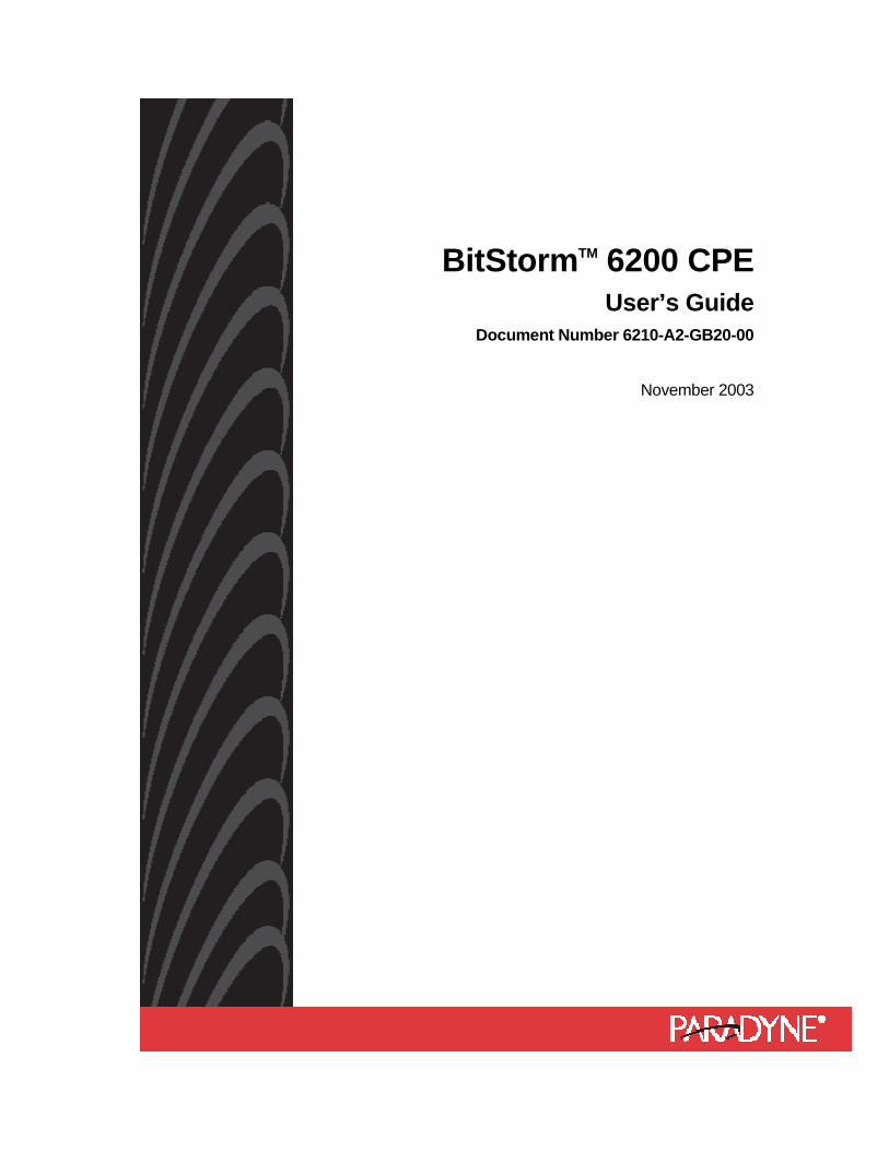
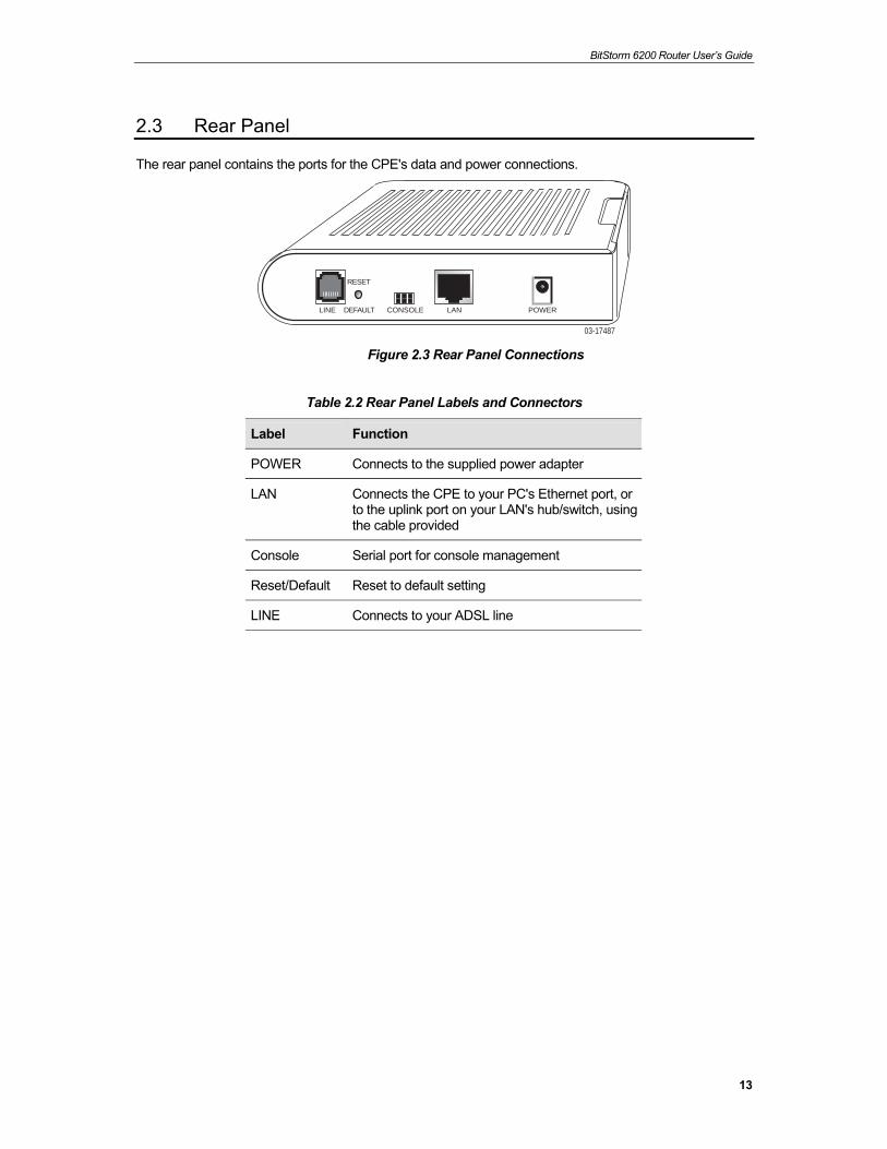
2.3 Rear Panel
The rear panel contains the ports for the CPE's data and power connections.
03-17487
LINE DEFAULT
RESET
CONSOLE LAN POWER
Figure 2.3 Rear Panel Connections
Table 2.2 Rear Panel Labels and Connectors
Label Function
POWER Connects to the supplied power adapter
LAN Connects the CPE to your PC's Ethernet port, or to the uplink port on your LAN's hub/switch, using the cable provided
Console Serial port for console management
Reset/Default Reset to default setting
LINE Connects to your ADSL line
BitStorm 6200 Router User’s Guide
14
3 Getting Started This chapter provides basic instructions for connecting the CPE to a computer or a LAN and to the Internet via ADSL.
Part 1 provides instructions to set up the hardware. Part 2 describes how to configure Internet properties on your computer(s). Part 3 shows you how to access your CPE.
It is assumed that you have already subscribed to ADSL service with your telephone company or other Internet service provider (ISP). These instructions provide a basic configuration that should be compatible with your home or small office network setup. Refer to the subsequent chapters for additional configuration instructions.
3.1 Connecting the Hardware
In 3.1, you should connect the device to an ADSL line, the power outlet, and your computer or network.
WARNING
Before you begin, turn the power off for all devices. These include your computer(s), your LAN hub/switch (if applicable), and the CPE.
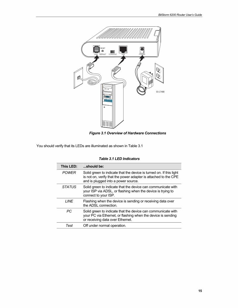
Figure 3.1 illustrates the hardware connections. Please follow the steps that follow for specific instructions.
3.1.1 Connect the ADSL line Connect your ADSL line to the port labeled LINE on the rear panel of the device, and connect the other end of the line to the wall phone jack directly or to an optional POTS splitter. If you use a POTS splitter to connect a telephone to the same wall jack as the CPE, follow the instructions that came with the splitter.
3.1.2 Connect the computers or a LAN You can use the included Ethernet cable to connect your computer directly to the CPE. Attach one end of the Ethernet cable to the port labeled LAN on the rear panel of the device and connect the other end to the Ethernet port of your computer.
If your LAN has more than one computer, you can attach one end of an Ethernet cable to a hub or a switch and the other to the port labeled LAN on the CPE.
Note that either a crossover or a straight-through Ethernet cable can be used. The CPE determines and adjusts to the type of signal required.
3.1.3 Attach the power adapter The supplied power adapter may look different than the one illustrated here.
Connect the cylindrical power plug into the POWER connector on the back of the device. If you have a wall-mount adapter, plug the AC adapter into a wall outlet or a power strip. If you have a table-top adapter, use the AC power cord to connect the adapter to a wall outlet or power strip.
3.1.4 Turn on your computer Turn on and boot up your computer and any other LAN devices, such as hubs or switches.
BitStorm 6200 Router User’s Guide
15
03-17488
LINE DEFAULT
RESET
CONSOLE LAN POWER
Figure 3.1 Overview of Hardware Connections
You should verify that its LEDs are illuminated as shown in Table 3.1
Table 3.1 LED Indicators
This LED: ...should be: POWER Solid green to indicate that the device is turned on. If this light
is not on, verify that the power adapter is attached to the CPE and is plugged into a power source.
STATUS Solid green to indicate that the device can communicate with your ISP via ADSL, or flashing when the device is trying to connect to your ISP.
LINE Flashing when the device is sending or receiving data over the ADSL connection.
PC Solid green to indicate that the device can communicate with your PC via Ethernet, or flashing when the device is sending or receiving data over Ethernet.
Test Off under normal operation.

BitStorm 6200 Router User’s Guide
16
3.2 Configuring Your PC
Before you start to access the CPE via Ethernet, you must configure your PC’s TCP/IP address to be 192.168.1.x, where x is any number between 3 and 254. The subnet mask must be 255.255.255.0. Your CPE’s default IP address is 192.168.1.1.
3.2.1 Windows XP: 1. In the Windows task bar, click on the Start button, and then click on Control Panel.
2. Double-click on the Network Connections icon.
3. In the LAN or High-Speed Internet window, right-click on the icon corresponding to your network interface card (NIC) and select Properties. (Often this icon is labeled Local Area Connection). The Local Area Connection dialog box is displayed with a list of currently installed network items.
4. Ensure that the check box to the left of the item labeled Internet Protocol (TCP/IP) is
checked, and click on .
.
Figure 3.2 Network Connections in Windows XP
Figure 3.3 Local Area Connection Properties in Windows XP
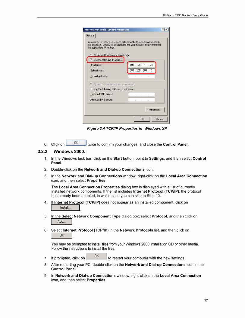
5. In the Internet Protocol (TCP/IP) Properties dialog box, click in the radio button labeled Use the following IP address and type 192.168.1.x (where x is any number between 3 and 254) and 255.255.255.0 in the IP address field and Subnet Mask field, respectively.
BitStorm 6200 Router User’s Guide
17
Figure 3.4 TCP/IP Properties in Windows XP
6. Click on twice to confirm your changes, and close the Control Panel.
3.2.2 Windows 2000: 1. In the Windows task bar, click on the Start button, point to Settings, and then select Control
Panel.
2. Double-click on the Network and Dial-up Connections icon.
3. In the Network and Dial-up Connections window, right-click on the Local Area Connection icon, and then select Properties.
The Local Area Connection Properties dialog box is displayed with a list of currently installed network components. If the list includes Internet Protocol (TCP/IP), the protocol has already been enabled, in which case you can skip to Step 10.
4. If Internet Protocol (TCP/IP) does not appear as an installed component, click on
.
5. In the Select Network Component Type dialog box, select Protocol, and then click on
.
6. Select Internet Protocol (TCP/IP) in the Network Protocols list, and then click on
.
You may be prompted to install files from your Windows 2000 installation CD or other media. Follow the instructions to install the files.
7. If prompted, click on to restart your computer with the new settings.
8. After restarting your PC, double-click on the Network and Dial-up Connections icon in the Control Panel.
9. In Network and Dial-up Connections window, right-click on the Local Area Connection icon, and then select Properties.
BitStorm 6200 Router User’s Guide
18
10. In the Local Area Connection Properties dialog box, select Internet Protocol (TCP/IP),
and then click on .
11. In the Internet Protocol (TCP/IP) Properties dialog box, click in the radio button labeled Use the following IP address and type 192.168.1.x (where x is any number between 3 and 254) and 255.255.255.0 in the IP address field and Subnet Mask field, respectively.
12. Click on twice to confirm and save your changes, and then close the Control Panel.
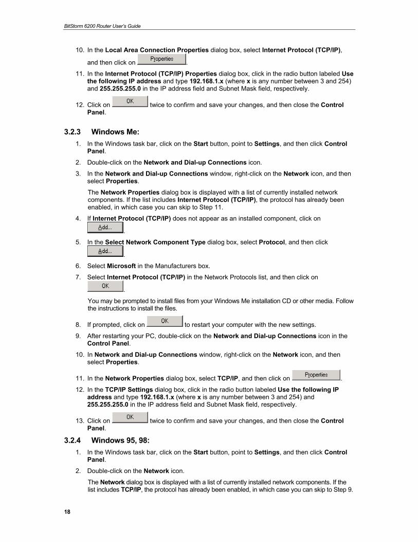
3.2.3 Windows Me: 1. In the Windows task bar, click on the Start button, point to Settings, and then click Control
Panel.
2. Double-click on the Network and Dial-up Connections icon.
3. In the Network and Dial-up Connections window, right-click on the Network icon, and then select Properties.
The Network Properties dialog box is displayed with a list of currently installed network components. If the list includes Internet Protocol (TCP/IP), the protocol has already been enabled, in which case you can skip to Step 11.
4. If Internet Protocol (TCP/IP) does not appear as an installed component, click on
.
5. In the Select Network Component Type dialog box, select Protocol, and then click
.
6. Select Microsoft in the Manufacturers box.
7. Select Internet Protocol (TCP/IP) in the Network Protocols list, and then click on
.
You may be prompted to install files from your Windows Me installation CD or other media. Follow the instructions to install the files.
8. If prompted, click on to restart your computer with the new settings.
9. After restarting your PC, double-click on the Network and Dial-up Connections icon in the Control Panel.
10. In Network and Dial-up Connections window, right-click on the Network icon, and then select Properties.
11. In the Network Properties dialog box, select TCP/IP, and then click on .
12. In the TCP/IP Settings dialog box, click in the radio button labeled Use the following IP address and type 192.168.1.x (where x is any number between 3 and 254) and 255.255.255.0 in the IP address field and Subnet Mask field, respectively.
13. Click on twice to confirm and save your changes, and then close the Control Panel.
3.2.4 Windows 95, 98: 1. In the Windows task bar, click on the Start button, point to Settings, and then click Control
Panel.
2. Double-click on the Network icon.
The Network dialog box is displayed with a list of currently installed network components. If the list includes TCP/IP, the protocol has already been enabled, in which case you can skip to Step 9.
BitStorm 6200 Router User’s Guide
19
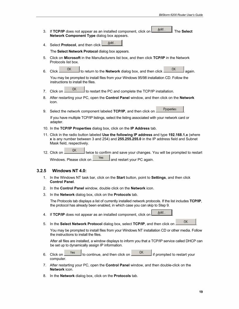
3. If TCP/IP does not appear as an installed component, click on . The Select Network Component Type dialog box appears.
4. Select Protocol, and then click .
The Select Network Protocol dialog box appears.
5. Click on Microsoft in the Manufacturers list box, and then click TCP/IP in the Network Protocols list box.
6. Click to return to the Network dialog box, and then click again.
You may be prompted to install files from your Windows 95/98 installation CD. Follow the instructions to install the files.
7. Click on to restart the PC and complete the TCP/IP installation.
8. After restarting your PC, open the Control Panel window, and then click on the Network icon.
9. Select the network component labeled TCP/IP, and then click on .
If you have multiple TCP/IP listings, select the listing associated with your network card or adapter.
10. In the TCP/IP Properties dialog box, click on the IP Address tab.
11. Click in the radio button labeled Use the following IP address and type 192.168.1.x (where x is any number between 3 and 254) and 255.255.255.0 in the IP address field and Subnet Mask field, respectively.
12. Click on twice to confirm and save your changes. You will be prompted to restart
Windows. Please click on and restart your PC again.
3.2.5 Windows NT 4.0: 1. In the Windows NT task bar, click on the Start button, point to Settings, and then click
Control Panel.
2. In the Control Panel window, double click on the Network icon.
3. In the Network dialog box, click on the Protocols tab.
The Protocols tab displays a list of currently installed network protocols. If the list includes TCP/IP, the protocol has already been enabled, in which case you can skip to Step 9.
4. If TCP/IP does not appear as an installed component, click on .
5. In the Select Network Protocol dialog box, select TCP/IP, and then click on .
You may be prompted to install files from your Windows NT installation CD or other media. Follow the instructions to install the files.
After all files are installed, a window displays to inform you that a TCP/IP service called DHCP can be set up to dynamically assign IP information.
6. Click on to continue, and then click on if prompted to restart your computer.
7. After restarting your PC, open the Control Panel window, and then double-click on the Network icon.
8. In the Network dialog box, click on the Protocols tab.
BitStorm 6200 Router User’s Guide
20
9. In the Protocols tab, select TCP/IP, and then click on .
10. In the Microsoft TCP/IP Properties dialog box, click in the radio button labeled Use the following IP address and type 192.168.1.x (where x is any number between 3 and 254) and 255.255.255.0 in the IP address field and Subnet Mask field, respectively.
11. Click on twice to confirm and save your changes, and then close the Control Panel.
3.2.6 Assigning IP to your PC automatically by DHCP To use the CPE’s DHCP feature (only available in the Model 6211), click in the radio button labeled Obtain an IP address automatically instead of Use the following IP address in the above procedures. By default, the LAN port IP address of the CPE is 192.168.1.1. (You can change this address, or
another address can be assigned by your ISP.)
Note
Your PCs must have IP addresses that place them in the same subnet as the CPE’s LAN port.
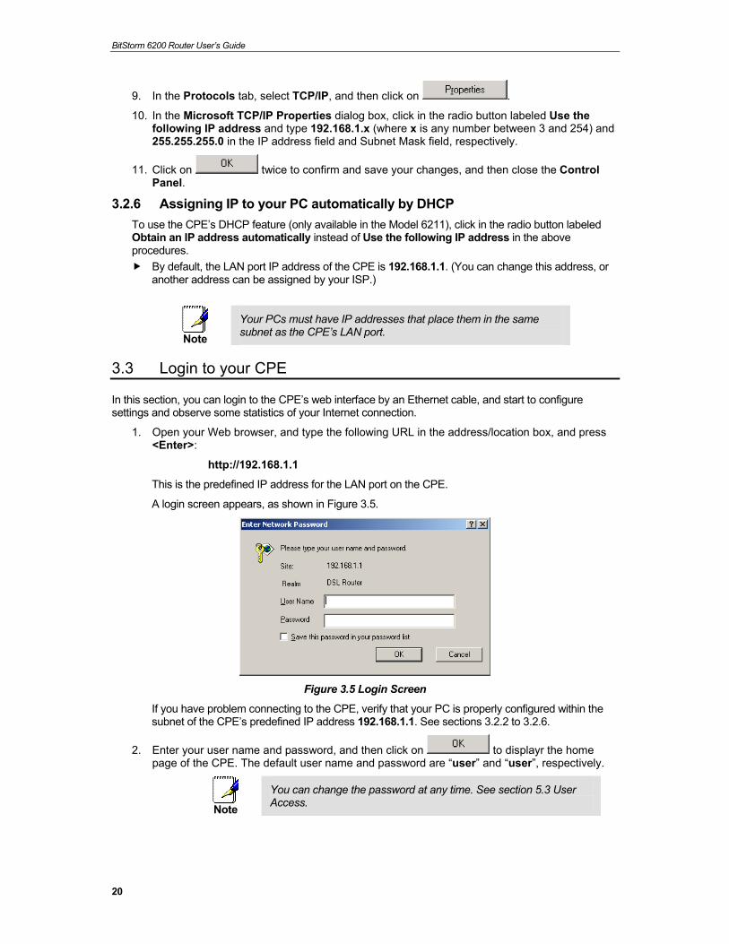
3.3 Login to your CPE
In this section, you can login to the CPE’s web interface by an Ethernet cable, and start to configure settings and observe some statistics of your Internet connection.
1. Open your Web browser, and type the following URL in the address/location box, and press <Enter>:
http://192.168.1.1
This is the predefined IP address for the LAN port on the CPE.
A login screen appears, as shown in Figure 3.5.
Figure 3.5 Login Screen
If you have problem connecting to the CPE, verify that your PC is properly configured within the subnet of the CPE’s predefined IP address 192.168.1.1. See sections 3.2.2 to 3.2.6.
2. Enter your user name and password, and then click on to displayr the home page of the CPE. The default user name and password are “user” and “user”, respectively.
Note
You can change the password at any time. See section 5.3 User Access.
BitStorm 6200 Router User’s Guide
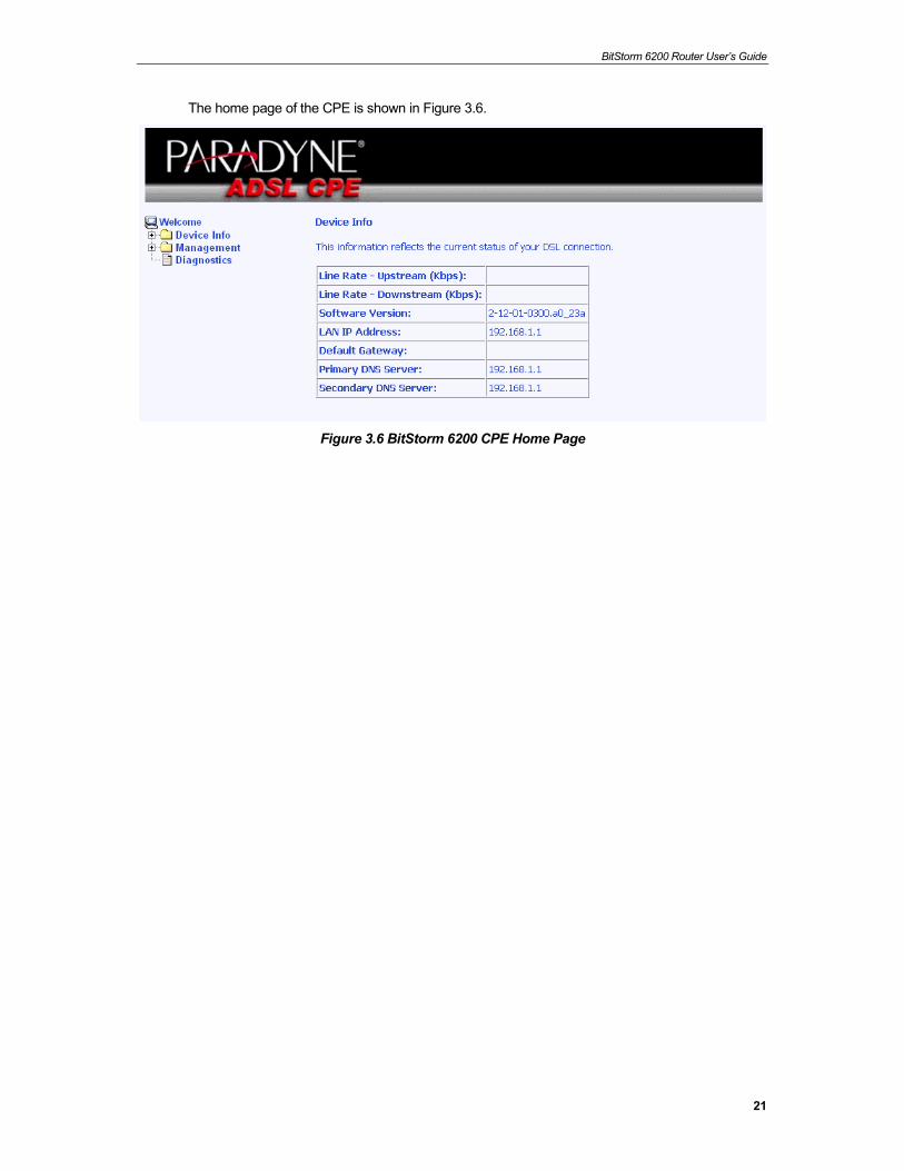
21
The home page of the CPE is shown in Figure 3.6.
Figure 3.6 BitStorm 6200 CPE Home Page
BitStorm 6200 Router User’s Guide
22
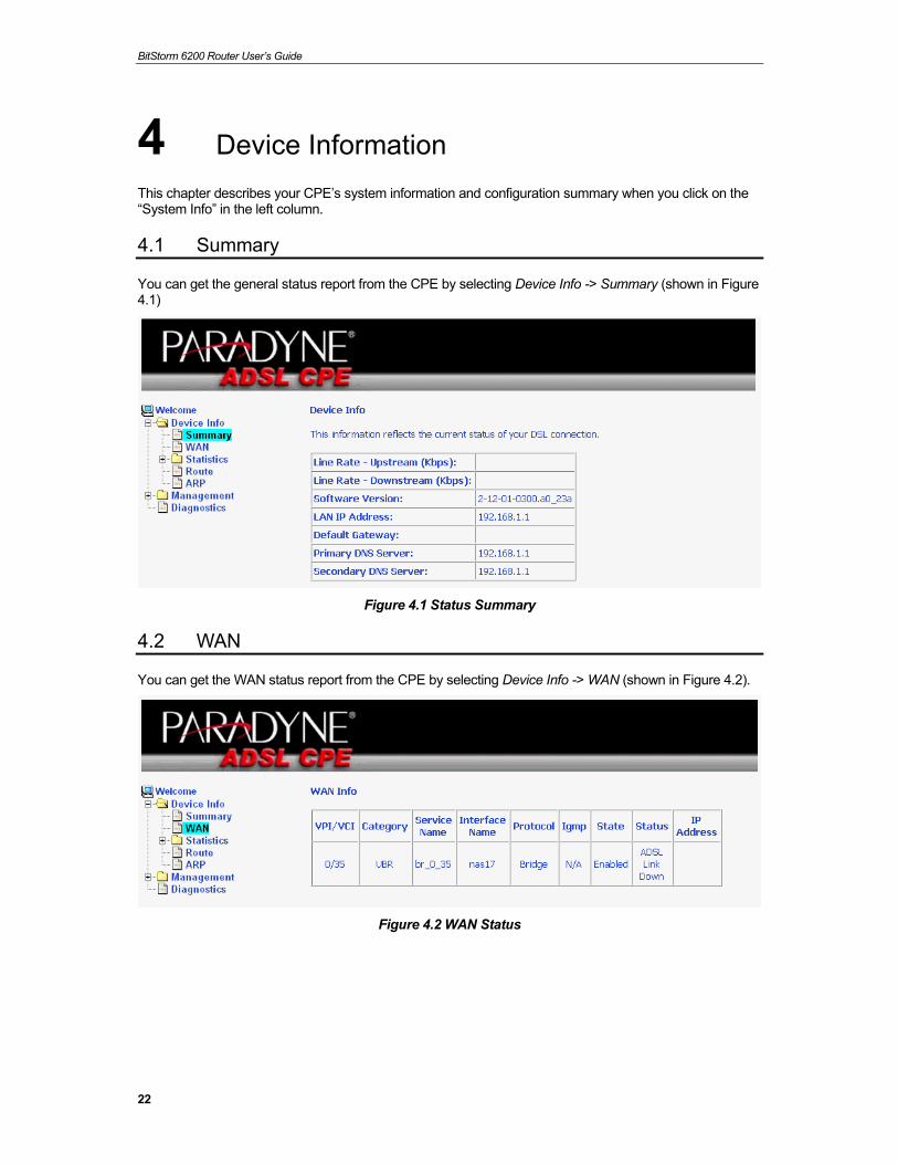
4 Device Information This chapter describes your CPE’s system information and configuration summary when you click on the “System Info” in the left column.
4.1 Summary
You can get the general status report from the CPE by selecting Device Info -> Summary (shown in Figure 4.1)
Figure 4.1 Status Summary
4.2 WAN
You can get the WAN status report from the CPE by selecting Device Info -> WAN (shown in Figure 4.2).
Figure 4.2 WAN Status
BitStorm 6200 Router User’s Guide
23
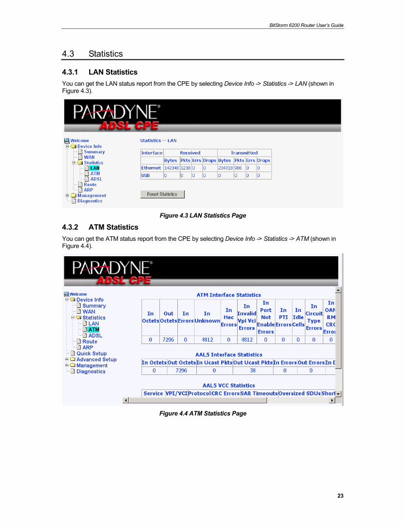
4.3 Statistics
4.3.1 LAN Statistics You can get the LAN status report from the CPE by selecting Device Info -> Statistics -> LAN (shown in Figure 4.3).
Figure 4.3 LAN Statistics Page
4.3.2 ATM Statistics You can get the ATM status report from the CPE by selecting Device Info -> Statistics -> ATM (shown in Figure 4.4).
Figure 4.4 ATM Statistics Page
BitStorm 6200 Router User’s Guide
24
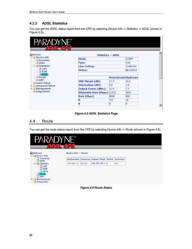
4.3.3 ADSL Statistics You can get the ADSL status report from the CPE by selecting Device Info -> Statistics -> ADSL (shown in Figure 4.5).
Figure 4.5 ADSL Statistics Page
4.4 Route
You can get the route status report from the CPE by selecting Device Info -> Route (shown in Figure 4.6).
Figure 4.6 Route Status
BitStorm 6200 Router User’s Guide
25
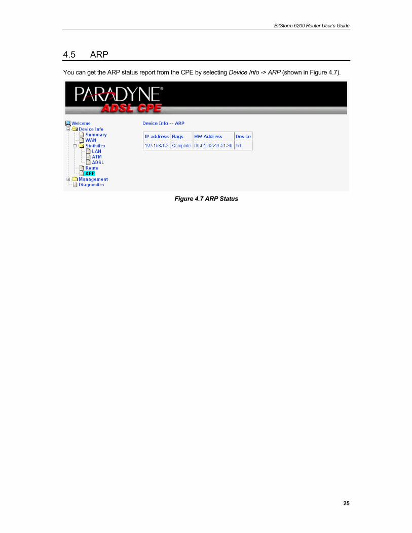
4.5 ARP
You can get the ARP status report from the CPE by selecting Device Info -> ARP (shown in Figure 4.7).
Figure 4.7 ARP Status
BitStorm 6200 Router User’s Guide
26
5 Management The chapter contains management instructions for software upgrade and restore configuration.
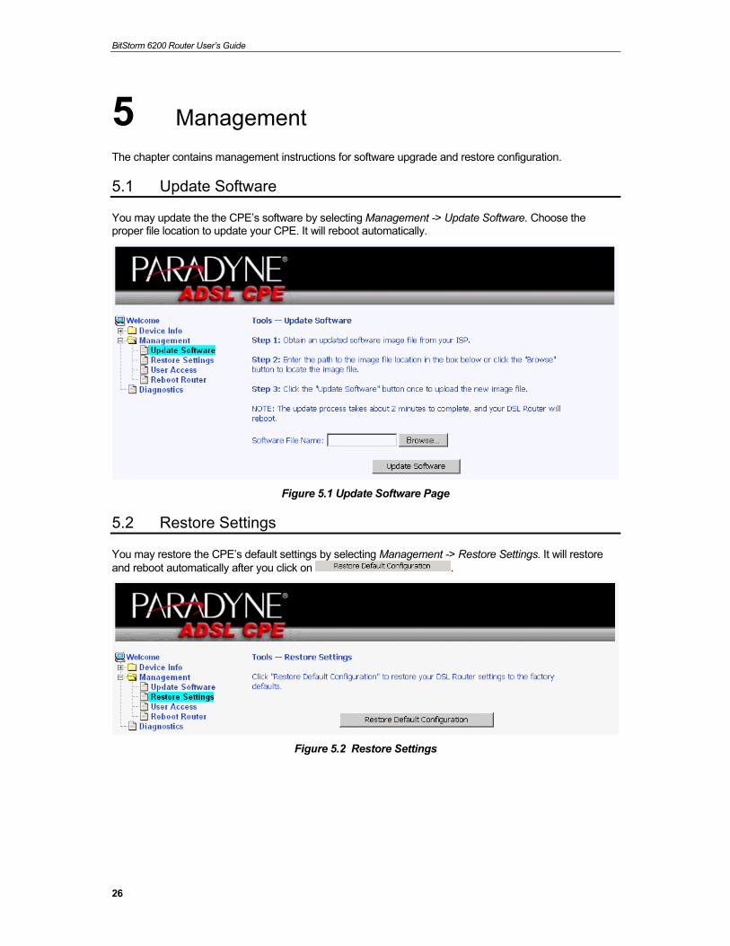
5.1 Update Software
You may update the the CPE’s software by selecting Management -> Update Software. Choose the proper file location to update your CPE. It will reboot automatically.
Figure 5.1 Update Software Page
5.2 Restore Settings
You may restore the CPE’s default settings by selecting Management -> Restore Settings. It will restore and reboot automatically after you click on .
Figure 5.2 Restore Settings
BitStorm 6200 Router User’s Guide
27
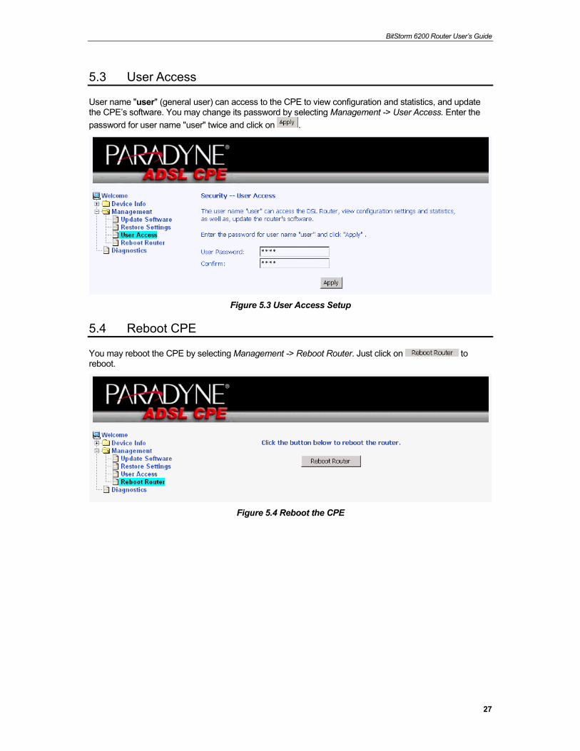
5.3 User Access
User name "user" (general user) can access to the CPE to view configuration and statistics, and update the CPE’s software. You may change its password by selecting Management -> User Access. Enter the password for user name "user" twice and click on .
Figure 5.3 User Access Setup
5.4 Reboot CPE
You may reboot the CPE by selecting Management -> Reboot Router. Just click on to reboot.
Figure 5.4 Reboot the CPE
BitStorm 6200 Router User’s Guide
28
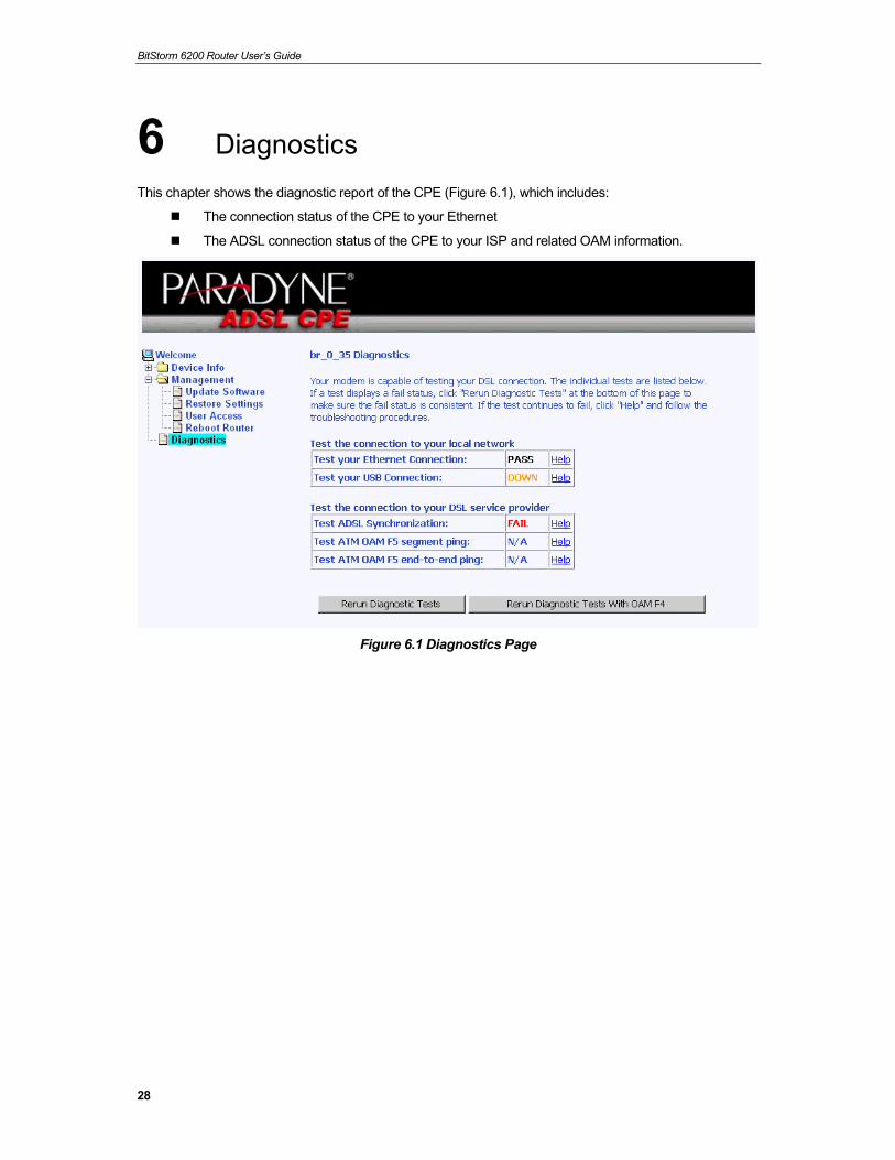
6 Diagnostics This chapter shows the diagnostic report of the CPE (Figure 6.1), which includes:
The connection status of the CPE to your Ethernet
The ADSL connection status of the CPE to your ISP and related OAM information.
Figure 6.1 Diagnostics Page

BitStorm 6200 Router User’s Guide
29
Index 6210, 9
6211, 9
ADSL Statistics, 24
ARP, 25
ATM Statistics, 23
bridge, 9
Connectors
rear panel, 13
Device Information, 22
Diagnostics, 28
Ethernet cable, 14
Features, 9
Front panel, 12
Hardware connections, 14, 15
Important Safety Instructions, 3
IP address, 20
IP configuration
static, 20
static IP addresses, 20
Windows 2000, 17
Windows 95/98, 18
Windows Me, 18
Windows NT 4.0, 19
Windows XP, 16
LAN port
default IP information, 20
LAN Statistics, 23
LEDs, 12
Login, 20
Management, 26
Network interface card, 9
Notational conventions, 9
Package contents, 11
Pages
Setup Wizard, 21
PC Configuration
static IP addresses, 20
Power adapter, 14
Rear Panel, 13
Reboot CPE, 27
Restore Settings, 26
Route status report, 24
Safety Instructions, 3
Setup Wizard page, 21
Static IP addresses, 20
Statistics, 23
System requirements:, 9
Typographical conventions, 10
Update Software, 26
User Access, 27
WAN status, 22
Web browser
requirements, 9
Windows NT
configuring IP information, 19


![INDEX [content.etilize.com]content.etilize.com/User-Manual/1037541780.pdf · Pulsar brevemente el botón 2 para reproducir / pausar la música en modo Bluetooth. Pulsar brevemente](https://img.pdfslide.us/doc/110x75/5e0f423d89f474440b3c4f3f/index-pulsar-brevemente-el-botn-2-para-reproducir-pausar-la-msica-en-modo.jpg)